Global 5000 Flight Crew Operating Manual (Volume 2)
BOMBARDIER GLOBAL 5000 · Flight Manual Supplement
Overview
The Bombardier Global 5000 Flight Manual Supplement provides detailed information about the aircraft's fuel system, including specifications, operational procedures, and system components. It covers the fuel management, transfer systems, and control mechanisms essential for safe flight operations.
- Fuel is stored in three main tanks: left wing, right wing, and center wing.
- The fuel system includes AC boost pumps and DC auxiliary pumps for engine feed.
- Fuel transfer from the center tank to wing tanks is automatic and controlled by the FMQGC.
- The aircraft features a single point pressure refuel/defuel system.
- Vent system ensures proper pressure control in fuel tanks.
- Fuel quantity and warnings are displayed on the EICAS.
- Gravity and pressure refueling options are available.
- The fuel management system monitors fuel quantity and balance.
Summary written by AI from the source document. Check the original before relying on it. See which parts of Sprinkle are written by AI.
Reference only, not for flight. Use the current approved manual for your aircraft. See terms, section 5.
Document
Source
Copy found at com.br. Sprinkle hosts a reference copy with an added summary, specifications and searchable full text.
Document details
- Type ·
- Flight Manual Supplement
- Year ·
- 2005
- File size ·
- 574 KB
- Copy found at ·
- com.br
- Language ·
- en
Specifications & performance
Extracted from this document.
Specifications
- Total fuel capacity (lb) ·
- 35616
What is the Global 5000 Flight Crew Operating Manual (Volume 2)?
The Global 5000 Flight Crew Operating Manual (Volume 2) is a flight manual supplement for the BOMBARDIER GLOBAL 5000, dated 2005.
What year was the Global 5000 Flight Crew Operating Manual (Volume 2) published?
The Global 5000 Flight Crew Operating Manual (Volume 2) — the BOMBARDIER GLOBAL 5000 flight manual supplement on file — is dated 2005.
Common. More common than 98% of the aircraft models we track.
Most owners only have the POH. Here's the essential set for the BOMBARDIER GLOBAL 5000.
- Pilot's Operating Handbook / AFM
- Checklist
- Maintenance Manual
- Parts Catalog (IPC)
- Systems & Wiring
- Service Bulletins on file
- Type Certificate (TCDS)
BOMBARDIER GLOBAL 5000 for sale now

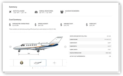
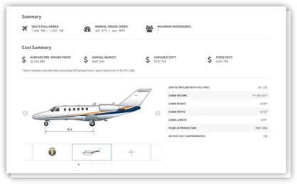
Free — save the 700 to your watchlist and track it in one place.
More BOMBARDIER GLOBAL 5000manuals & documents
Related documents
- Cessna Citation XLS - Fuel SystemCessna Citation XLS+ · Normal Procedures
- 1972 Cessna 210L POH.pdf - Take Flight San DiegoCESSNA TURBO 210L · Pilot's Operating Handbook
- Cessna 1971 Super Skymaster 337 POH - JasonBlair.netCessna 337 Super Skymaster · Pilot's Operating Handbook
- Cessna Citation 500/501 Type Rating Technical Examination V0.1Cessna Citation 500 · Pilot's Operating Handbook
- 1973 177B POH - CESSNACESSNA 177B · Pilot's Operating Handbook
If you fly the BOMBARDIER GLOBAL 5000, you may also be researching these.


In this document
Fuel Specifications
Details on fuel additives, temperature limitations, and approved fuels are referenced from the Airplane Flight Manual.
Fuel System Overview
The fuel system consists of three main tanks and utilizes a combination of AC and DC pumps for fuel management and transfer.
Fuel Control Panel
Located in the flight compartment, it allows for manual control and monitoring of the fuel system components.
Vent System
An open vent system controls pressure in the fuel tanks, ensuring adequate venting and preventing over-pressurization.
Transfer System
Fuel transfer from the center tank to wing tanks is automatic, managed by the FMQGC based on fuel levels.
Refuel/Defuel System
The aircraft is equipped with a single point pressure refuel/defuel adapter for efficient refueling operations.
Safety notes
- Fuel remaining in a tank when the indicator reads zero is not usable.
- Any fault detected by the fuel system is annunciated on EICAS.
- The vent system is fully redundant to ensure venting capability.
- Relief valves protect tanks from over-pressurization.
- Manual override for center tank transfer is not available.
Full document text
DESCRIPTION General 12−10−1 Fuel Specifications 12−10−2 Fuel System Synoptic Page 12−10−3 AC Boost Pumps 12−10−3 DC Auxiliary Pumps 12−10−3 Center Transfer Pumps 12−10−4 Fuel Control Panel 12−10−4 Fuel Tanks 12−10−5 Service Points 12−10−5 Vent System 12−10−6 Vent System Schematic 12−10−6 Transfer System 12−10−7 Center Transfer 12−10−7 Wing Transfer 12−10−7 Auto Wing Transfer 12−10−8 Manual Wing Transfer 12−10−8 Crossfeed 12−10−8 Engine Feed System 12−10−11 Engine Feed System Indication 12−10−11 APU Fuel Feed 12−10−13 Fuel Quantity and Indication 12−10−14 Flight Management Display 12−10−15 Refuel/Defuel System 12−10−16 Refuel/Defuel Panel 12−10−17 Normal Fuel Loading 12−10−18 Gravity Refueling 12−10−18 Pressure Refueling 12−10−18 Manual Refueling 12−10−19 Suction Defueling 12−10−19 Pressure Defueling 12−10−19 Fault Reporting 12−10−19 Error Messages 12−10−19 INHIBIT 12−10−20 FULL 12−10−20 LOAD ERROR 12−10−20 FUEL TABLE OF CONTENTS CHAPTER 12 12−00−1 Rev 3, Apr 25, 2005 Flight Crew Operating Manual CSP 700−5000−6 Volume 2 12−00−1 Page TABLE OF CONTENTS DESCRIPTION IMBAL 12−10−20 REPEATER 12−10−20 FAILED 12−10−20 FMQGC − FAILURE 12−10−20 Refueling Distribution 12−10−21 Refuel/Defuel Schematic 12−10−22 Fuel Re-Circulation System 12−10−23 Fuel Filters, Quantity and Temperature Readouts 12−10−25 Fuel Pump Displays 12−10−26 Fuel Shutoff Displays 12−10−27 Fuel Synoptic Page Symbols 12−10−28 EICAS Philosophy 12−10−28 Fuel Management Quantity Gauging System (FMQGS) 12−10−28 FMQGC Schematic 12−10−29 EICAS Messages 12−10−30 EMS CIRCUIT PROTECTION CB − Fuel System 12−20−1 FUEL TABLE OF CONTENTS Rev 3, Apr 25, 2005 Flight Crew Operating Manual CSP 700−5000−6 Volume 2 12−00−2 Page GENERAL Fuel is contained in a wet wing box structure, which is sealed to form three main separate wing tanks (left wing, right wing and center wing). The tanks are vented to atmosphere and slightly pressurized by an air scoop located on the lower surface of each wing. A scavenge pump purges fuel from the vent lines and a climb vent, located in each main wing tank, provides ventilation when the airplane is in a nose up attitude. Each engine is supplied with fuel from its respective feed tank which contains two alternating current or AC primary pumps and one Direct Current (DC) back up boost pump. The transfer system maintains the feed tanks full during all attitudes and provides automatic transfer of fuel from the center tank to the main wing tanks. Lateral balance between left and right main tanks is controlled automatically by the Fuel Management and Quantity Gauging Computer (FMQGC) or manually through switch selections in the flight compartment. FGF1210_001 ENGINE DRIVEN PUMPS AC MOTOR PUMPS AC MOTOR PUMPS (TRANSFER) CENTER TANK MAIN WING TANK DC PUMPS (START, EMERGENCY FEED TANKS AND WING TRANSFER) (ENGINE FEED) Flight deck control is provided on the overhead panel and fuel quantity and warnings are displayed on EICAS. A single point pressure refuel/defuel adapter is provided which is connected to a manifold containing shutoff valves. Pressure refueling can be done either automatically or manually. Gravity filling is provided for each tank. FUEL Rev 3, Apr 25, 2005 Flight Crew Operating Manual CSP 700−5000−6 Volume 2 12−10−1 GENERAL (CONT'D) A dual channel FMQGC continuously monitors the following: • Fuel quantity indicating • Left, right engine and APU feed • Wing to wing balance (wing XFER) • Center tank transfer • Refuel/defuel • Fuel recirculation Any fault detected by the fuel system computer is annunciated on Engine Indication and Crew Alerting System (EICAS), in the form of a visual and/or aural alert and/or maintenance diagnostics. FUEL SPECIFICATIONS For information on fuel additives, temperature limitations and approved fuels, refer to Airplane Flight Manual (AFM) CSP 700−5000−1 − LIMITATIONS Chapter. Fuel remaining in a tank when the appropriate fuel quantity indicator reads zero is not usable. Refer to the AFM CSP 700−5000−1 for exact tank and total fuel quantity. FUEL Rev 3, Apr 25, 2005 Flight Crew Operating Manual CSP 700−5000−6 Volume 2 12−10−2 FUEL SYSTEM SYNOPTIC PAGE The FUEL synoptic page provides an overview of system status, as represented below with both left and right engines running and no transferring of fuel taking place. DC AUXILIARY PUMPS AC BOOST PUMPS CENTER TRANSFER PUMPS FGF1210_002 FUEL TOTAL FUEL 35616 LBS FUEL USED 0 LBS 14900 LBS 14900 LBS 5816 LBS AUX AUX °C 23 °C 23 P P P P P APU °C 32 P P P °C 32 AC Boost Pumps Two AC boost pumps, also referred to as primary boost pumps, are located in each feed tank. They normally supply fuel to the engines in all airplane ground and flight mode operations. Each pump is capable of maintaining an engine (fuel demand) in all modes of engine operation. The two pumps are continuously on, whenever the engine is operating and AC power is available. Both boost pumps (two on each side) may be inhibited by selection of one of the individual switches on the fuel control panel. The boost pumps are controlled automatically through the Alternating Current Power Center (ACPC), when a fuel command is received. DC Auxiliary Pumps DC powered auxiliary pumps (AUX pumps) one in each feed tank, are used for the following: • APU starting • Wing to wing transferring of fuel • Engine feed in the event of an AC boost pump failure • During takeoff and landing with at least one of the following: Flaps > 0°, landing gear down and in flight, or low wing fuel condition (600 pounds each wing) Each AUX pump may be inhibited by selecting off a switch on the fuel control panel. The pumps are automatically controlled by the Secondary Power Distribution Assembly (SPDA). FUEL Rev 2A, Apr 11, 2005 Flight Crew Operating Manual CSP 700−5000−6 Volume 2 12−10−3 FUEL SYSTEM SYNOPTIC PAGE (CONT'D) Center Transfer Pumps
Show full textShow less
Two center transfer pumps (controlled by the FMQGC) are used to transfer fuel from the center tank to the main wing tank. There is no manual selection available to transfer fuel from the center tank to the wings. FUEL CONTROL PANEL The fuel control panel is located on the overhead panel in the flight compartment. The fuel control panel defines the operational modes, component controls and component inhibits. The fuel control panel has switches, which when selected, override the automatic control of certain components within the fuel system. Switch selections from this panel are sent to the ACPC. The ACPC will then control the system from the inputs received from the panel. The switch lamps come on in combination with certain EICAS messages, which represent the panel configuration or failure within a given system. FGF1210_003 selection − Provides a means of transferring fuel from one wing to the other. Controlled by the FMQGC. selection − A left to right or a right to left selection, provides a means of transferring fuel (in the direction of the arrow) from one wing tank to the other. selection − Provides a method of inhibiting wing to wing transfer. PRI PUMPS Switch light − Indicates that both left wing primary pumps have been disarmed. The right PRI PUMPS switch has similar logic. AUX PUMP switch light − Indicates that the right auxiliary pump has been disarmed. The left AUX PUMP has similar logic. XFEED SOV switch light − Will come on when the valve does not go to the commanded position. light − When the switch is selected, the crossfeed valve opens and interconnects the engine feed lines. RECIRC INHIBIT switch light − Indicates that the FRTT valve is closed when commanded by the flight crew. AUTO <− or −> OFF OPEN OFF OFF AUX PUMP has similar FAIL OFF AUTO WING XFER OFF WING FEED INHIBIT AUX PUMP OFF PRI PUMP OFF INHIBIT L WING FEED INHIBIT AUX PUMP OFF PRI PUMP OFF INHIBIT R XFEED SOV FAIL OPEN WING XFEED switch OFF OFF L RECIRC R RECIRC FUEL Rev 2A, Apr 11, 2005 Flight Crew Operating Manual CSP 700−5000−6 Volume 2 12−10−4 FUEL TANKS All fuel is carried in three integral tanks (left wing, right wing and center wing). The inboard section of each wing is designated as a feed tank, from which each engine draws its fuel. Fuel flows from the outboard sections of each wing tank, into the feed tank (by gravity), through swing check valves in the baffles of each main tank. The check valves allow fuel flow in the inboard direction only. This will restrict large fuel movements and limit center of gravity shifts in airplane changes of attitude. Fuel is also transferred into the feed tanks from the center wing tank by the transfer system. SERVICE POINTS FGF1210_004 WING FUEL TANK WATER DRAIN WING FUEL TANK GRAVITY FUEL FILL CENTER WING GRAVITY FUEL FILL WING FUEL TANK WATER DRAIN CENTER FUEL TANK WATER DRAINS GRAVITY FUEL FILL LEGEND LOWER SURFACE UPPER SURFACE All tanks have flush self-closing water drain valves, installed at various low points, to permit draining of any accumulated water or residual fuel. They are located at the low point of each wing. Three gravity fill caps are provided for wing and center tank gravity refueling. FUEL Rev 2A, Apr 11, 2005 Flight Crew Operating Manual CSP 700−5000−6 Volume 2 12−10−5 VENT SYSTEM An open vent (no float valves or flame arrestors) system is used to control the pressure in the fuel tanks. It consists of vent line tubing and ram air outlets (scoops) to ensure adequate venting of all fuel tanks. The vent lines connect the two air scoops to the fuel tanks and the fuel tanks to each other. The lines are drained of fuel which is returned to the feed tanks during operation. The low point of the main vent line is continuously scavenged by a jet pump. The vent line distribution is to a high point in the fuselage, preventing fuel from reaching either of the two ram outlets and spilling overboard. If any fuel passes the high point, it is collected by the surge box and is drained back to the tank before it reaches the outlet. Each surge box vent line tubing runs vertically along the fuselage side wall and is coupled to the wing and center tanks. The vent system is fully redundant such that any single blockage does not affect the venting capability. VENT SYSTEM SCHEMATIC FGF1210_005 LEFT WING TANK RIGHT WING TANK CENTER WING TANK LEFT SURGE BOX RIGHT SURGE BOX AIR SCOOP AIR SCOOP Relief valves are used to protect the tanks from over pressurization, in the case of failure of the vent system and/or refuel shutoff valve. They are located in the wing and center tanks. FUEL Rev 2A, Apr 11, 2005 Flight Crew Operating Manual CSP 700−5000−6 Volume 2 12−10−6 TRANSFER SYSTEM Fuel contained in the center tank cannot be fed directly to the engine, but must be first delivered to the feed tanks by the transfer pumps. The normal sequence of fuel usage is to transfer center tank fuel into the wings as required to keep the wings full during climb and cruise. After depletion of center tank fuel quantity, no further transfer of fuel is required, since all remaining fuel is contained in the wing tanks. Control of fuel transfer from the center tank is normally under control of the fuel computer. There is no manual override for the center tank transfer system. Center Transfer Fuel transfer from the center tank to wing tank is completely automatic through the control of the FMQGC. The FMQGC monitors the fuel level and quantities in the wing tank (using fuel probes, compensators, densitometers and temperature sensors) to control fuel transfer from the center tank to the wing tanks. Fuel will be transferred from the center tank and delivered to the wing feed tanks, through the use of two center transfer pumps. The FMQGC will start the applicable center transfer pump(s) when each individual wing tank reaches approximately 93% of its fuel tank capacity. The FMQGC will automatically stop the center transfer pump(s) when the respective wing tank reaches greater than 97% of its fuel tank capacity. CENTER TRANSFER PUMPS FGF1210_006 FUEL TOTAL FUEL 35616 LBS FUEL USED 0 LBS 14900 LBS 14900 LBS 5816 LBS AUX AUX °C 23 °C 23 P P P APU °C 32 P P P °C 32 P P The FUEL synoptic page represents the center tank transfer operation with both engines running. Wing Transfer The wing transfer system permits fuel to be pumped from either side of the airplane to the other, using the DC auxiliary pumps and motor operated shutoff valves. The wing transfer system provides a means of correcting lateral fuel imbalance. It may be used in automatic mode via FMQGC or manual mode as selected by the cockpit fuel control panel. Fuel imbalance at a predetermined value will be annunciated on the EICAS display in the form of a caution message. FUEL Rev 2A, Apr 11, 2005 Flight Crew Operating Manual CSP 700−5000−6 Volume 2 12−10−7 TRANSFER SYSTEM (CONT'D) Auto Wing Transfer The auto wing transfer mode is only enable when the slat/flap handle is in the In the wing transfer automatic mode, the FMQGC will correct lateral fuel imbalances of 400 pounds on ground and in flight. The FMQGC will control and operate the DC auxiliary pumps and wing transfer SOV’s as necessary to pump fuel from the feed tank into the opposite wing. Once commanded on, the wing transfer system remains on until lateral fuel imbalance is zero. In the event of a center tank transfer pump failure, fuel will be transferred from the operating center tank transfer pump to its respective wing tank. The automatic wing transfer system will maintain lateral fuel balance, to ensure that fuel contained in the center tank is available to both engines. Manual Wing Transfer In manual mode, the wing transfer system is controlled using the fuel WING XFER switch. Once selected, the wing fuel transfer continues until the WING XFER switch is selected OFF on the fuel control panel. DC Auxiliary Pump In wing transfer demand, commanded on by the FMQGC. Wing Transfer Shutoff Valve Commanded on by the FMQGC or manually by the switch on the fuel control panel. FGF1210_007 AUTO WING XFER OFF FUEL TOTAL FUEL 28300 LBS FUEL USED 7316 LBS 13400 LBS 14900 LBS 0 LBS AUX AUX °C 23 °C 23 P P P P APU °C 32 P P P °C 32 P The FUEL synoptic page represents the left to right wing transfer mode of operation with both engines running. Crossfeed The crossfeed system permits interconnection between the left and right engine feed lines, using a shutoff valve. This will enable both engines to be fed by either feed tank or alternatively enable a single engine to be supplied from both feed tanks. For normal airplane operations, the crossfeed shutoff valve is closed, isolating the feed lines and ensuring that each engine is supplied fuel only from its own side of the airplane. Opening the crossfeed shutoff valve interconnects the feed lines, enabling fuel to flow from one engine feed line to the other. No automatic means of controlling the crossfeed SOV is provided and selection has to be made using the XFEED SOV switch on the fuel control panel. FUEL Rev 2A, Apr 11, 2005 Flight Crew Operating Manual CSP 700−5000−6 Volume 2 12−10−8 TRANSFER SYSTEM (CONT'D) Crossfeed (Cont’d) In single engine operating mode with the crossfeed shutoff valve opened, fuel flows from both feed tanks via the AC primary pumps to the single engine and fuel flow rates from both sides of the airplane are considered essentially the same. Therefore the airplane can be flown indefinitely without developing any significant lateral fuel imbalance. Engine Feed Shutoff Valve Commanded off when the fire handle is pulled. Crossfeed Shutoff Valve Crossfeed shutoff valve is selected open by the switch on the fuel control panel. FGF1210_008 XFEED SOV FAIL OPEN FUEL TOTAL FUEL 28300 LBS FUEL USED 7316 LBS 13400 LBS 14900 LBS 0 LBS AUX AUX °C 23 °C 23 P P P P APU °C 32 P P P °C 32 P LO PRESS The FUEL synoptic page represents the fuel crossfeed mode of operation, with the crossfeed shutoff valve selected open, left engine shut down, left engine feed shutoff valve closed and the right engine running. A secondary use of the crossfeed system (as a backup to the wing transfer system) is to provide means of correcting lateral C of G imbalances, by temporarily inhibiting the flow fuel from the light side of the airplane. Fuel will then be supplied to both engines from the heavy side until lateral fuel imbalance is within desired limits. CAUTION The possibility of engine flameout could occur, if the crossfeed valve is not opened prior to inhibiting the fuel pumps. In this operating mode, the crossfeed valve is selected open via the XFEED SOV switch on the fuel control panel. The fuel pumps on the light side of the airplane are turned off, using the applicable AUX PUMP and PRI PUMP switches. Fuel will then be supplied from the heavy side of the airplane only, thereby correcting the lateral fuel imbalance. Crossfeed continues in this mode until the crew deselects the switches after lateral balance is achieved. NOTE It is important that the crew monitor system operation in this mode, since crossfeed will continue until manually deselected. FUEL Rev 2A, Apr 11, 2005 Flight Crew Operating Manual CSP 700−5000−6 Volume 2 12−10−9 TRANSFER SYSTEM (CONT'D) Crossfeed (Cont’d) In the event that a lateral fuel imbalance occurs outside design limits, it will be annunciated on EICAS, prompting the crew to take action. Crossfeed Shutoff Valve Crossfeed shutoff valve is selected open by the switch on the fuel control panel. L WING FEED INHIBIT FGF1210_009 AUX PUMP OFF PRI PUMP OFF XFEED SOV FAIL OPEN FUEL TOTAL FUEL 26300 LBS FUEL USED 9316 LBS 14900 LBS 12900 LBS 5816 LBS AUX AUX °C 23 °C 23 P P P P P APU °C 32 P P P °C 32 The FUEL synoptic page represents the fuel crossfeed mode (backup) of operation. The system is shown with the crossfeed shutoff valve selected open, left auxiliary pump inhibited, left forward pumps inhibited and both engines running. FUEL Rev 2A, Apr 11, 2005 Flight Crew Operating Manual CSP 700−5000−6 Volume 2 12−10−10 ENGINE FEED SYSTEM Fuel is provided to each engine from the two AC boost pumps. In normal operation, both boost pumps are continuously on and provide all engine fuel flow once the engine is started. The AC pumps are located in the inboard section of each wing (feed tank) and each AC pump is powered by a separate bus. Loss of pressure at any AC boost pump causes the DC pump to come on, to provide a back up of the remaining boost pump. The DC pumps also come on automatically for take-off, based on flaps/slats position and weight on wheels logic. The engine fuel burn schedule is automatically controlled by the FMQGC to ensure correct distribution for all airplane configurations. The engine fuel burn sequence is as follows: • Fuel from the wing tanks will be consumed first, • When the wing tanks get below 93%, fuel transfers from the center tank to the wing tank until it is at or above 97%, • When the center tank empties, fuel from the wing tanks continue to burn. Engine Feed System Indication The left FUEL synoptic page below represents the normal engine start mode of operation. The right engine is started using the Auxiliary Power Unit (APU) as the source of electrical power and left engine is off. The right FUEL synoptic display represents the right engine on speed. FGF1210_010 FUEL TOTAL FUEL 35316 LBS FUEL USED 300 LBS 14900 LBS 14900 LBS 5516 LBS AUX AUX °C 23 °C 23 P P P APU °C 32 P P P °C 32 P P FUEL TOTAL FUEL 35316 LBS FUEL USED 300 LBS 14900 LBS 14900 LBS 5516 LBS AUX AUX °C 23 °C 23 P P P APU °C 32 P P P °C 32 P P LO PRESS LO PRESS FUEL Rev 3, Apr 25, 2005 Flight Crew Operating Manual CSP 700−5000−6 Volume 2 12−10−11 ENGINE FEED SYSTEM (CONT'D) Engine Feed System Indication (Cont’d) The FUEL synoptic display below represents airplane configuration with the APU shutdown, both engines on speed, AC pumps running and the DC pumps on standby. FGF1210_011 FUEL TOTAL FUEL 35316 LBS FUEL USED 300 LBS 14900 LBS 14900 LBS 5516 LBS AUX AUX °C 23 °C 23 P P P APU °C 32 P P P °C 32 P P FUEL Rev 3, Apr 25, 2005 Flight Crew Operating Manual CSP 700−5000−6 Volume 2 12−10−12 APU FUEL FEED The APU start capability is normally provided by the DC AUX pump(s). The fuel supplied to the APU is taken from the right engine feed line. The APU can also be fed from the left engine feed line using the left DC AUX pump (powered by DC ESS bus) and opening the crossfeed shutoff valve (BATT bus). A motor operated fire shutoff valve is used in the APU feed line, in order to isolate the flow of fuel to the APU in case of a fire or rotor burst. The FUEL synoptic page top view represents the APU starting with the right DC pump running and battery power only as the single source of electrical power. In the lower view, the APU is fed from the right engine feed line using the AC pumps. APU start in progress, left and right engines are off. APU FEED SHUTOFF VALVE Green outline will be indicated when the APU is on speed. TOP VIEW FGF1210_012 NOTE APU − FUEL TOTAL FUEL 38400 LBS FUEL USED 300 LBS 14600 LBS 14600 LBS 9200 LBS AUX AUX °C 23 °C 23 P P P APU °C 32 P P P °C 32 P P LO PRESS LO PRESS APU on speed, left and right engines on and AC electrics established. LOWER VIEW FGF1210_013 NOTE FUEL TOTAL FUEL 35616 LBS FUEL USED 0 LBS 14900 LBS 14900 LBS 5816 LBS AUX AUX °C 23 °C 23 P P P APU °C 32 P P P °C 32 P P FUEL Rev 2A, Apr 11, 2005 Flight Crew Operating Manual CSP 700−5000−6 Volume 2 12−10−13 FUEL QUANTITY AND INDICATION The fuel quantity gauging system is an ac-type capacitance system. Fuel quantity probes, compensators, densitometers, temperature sensors and high level detectors provide inputs to the FMQGC. The FMQGC uses these acquired data to compute the fuel quantity for each tank and total fuel quantity remaining on board the airplane. The FMQGC provides the computed individual fuel tank, total quantity and fuel temperature for EICAS display. The fuel system computer corrects for airplane pitch attitude and presents the corrected information of individual tank quantities and total fuel quantity displayed on EICAS. Fuel FLow Readout Indicates fuel flow in pounds per hour (PPH) to the respective engine. EICAS PRIMARY DISPLAY Total Fuel Readout Indicates total fuel quantity in pounds (lbs), of all the tanks. Green − Total fuel quantity is valid and in normal range. Amber − The fuel quantity is low. Dashed − Fuel quantity is not valid. Fuel Quantity Readout (wing tank) Indicates fuel quantity in the respective wing tank, in pounds (lbs). Green − Left and right tanks are balanced. Amber − A fuel quantity imbalance exists or applicable tank is less than 600 lbs (272 KG). Dashed − Fuel quantity is not valid Fuel Quantity Readout (center fuselage tank) Indicates fuel quantity in the center tank, in pounds (lbs). Green − Quantity is valid. Dashed − Fuel quantity is not valid. TOTAL FUEL (LBS) 35016 14600 14600 5816 ND STAB NU RUDDER NL LWD RWD NR TRIMS 7.2 N2 FF (PPH) OIL TEMP OIL PRESS 93.4 5750 115 81 93.4 5750 115 81 AIL FGF1210_014 The FMQGS can display fuel quantity in either LB (standard) or KG (optional). The primary EICAS page displays fuel quantity in all fuel tanks and total fuel in the airplane. FUEL Rev 2A, Apr 11, 2005 Flight Crew Operating Manual CSP 700−5000−6 Volume 2 12−10−14 FLIGHT MANAGEMENT DISPLAY When both engines are started, the Fuel Management System (FMS) fuel quantity switches from Fuel Management Quantity Gauging System (FMQGS), to computed fuel quantity, based on fuel flow data from the engines and APU. GF1210_017a Compare Fuel Quantity Displays when the gauge fuel weight and the FMS fuel weight differ by more than 2% of the Basic Operating Weight (BOW). BOW 48500 5/170 PASS / @ LB PERFORMANCE INIT−LB 5/5 FUEL (GAUGE) 25300 (25300) ACTIVE FLT PLAN ORIGIN KPHX 055 154 NM CLS 1/4 00 + 21 .75M/ A 10000 SJN 059 121 NM 00 + 15 .75M/10000 A TAKEOFF INIT ABQ DEPARTURE 0 0 COMPARE FUEL QUANT CLS 850 PASS WT Fuel quantity information to the FMS is used for monitoring and sensing, to assist in determining a fuel leak. When a fuel leak is detected, a crew alert (“MSG” on the primary flight display) will be displayed and a message will appear on the scratchpad of the FMS CDU. FUEL Rev 2A, Apr 11, 2005 Flight Crew Operating Manual CSP 700−5000−6 Volume 2 12−10−15 REFUEL/DEFUEL SYSTEM Pressure refueling/defueling operations are controlled from the refuel/defuel control panel. Pressure refueling can be accomplished in MANUAL or AUTO mode of operation. FGF1210_015 GRAVITY FILL CAP GROUNDING POINTS GROUNDING POINT REFUEL/DEFUEL ACCESS PANEL PROXIMITY SENSOR GROUNDING POINT REFUEL/DEFUEL PANEL LOCATION CLOSE OPEN REFUEL/DEFUEL PANEL LEFT CENTER RIGHT PRESEL TOTAL MANUAL LEFT CTR RIGHT OPEN CLOSE INCR DECR PRESEL START STOP/ SOV TEST REFUEL DEFUEL AUTO OFF MANUAL REFUEL Gravity filling via a filler point is also provided for the wing and center wing tanks. FUEL Rev 2A, Apr 11, 2005 Flight Crew Operating Manual CSP 700−5000−6 Volume 2 12−10−16 REFUEL/DEFUEL PANEL FGF1210_016 PRESELECT TOTAL QTY DISPLAY Displays the fuel quantity target for automatic refueling. Set in 100 lb (50 KG) increments. LEFT/RIGHT/CTR/TOTAL Displays the current fuel quantity in each tank and the total quantity in all tanks. Quantities are displayed in 50 lb (25 KG) increments. PRESEL INCR/DECR Increases or decreases the preselect quantity for AUTO refueling. FUEL SOVs Allows tanks to be refueled or defueled manually. MODE SELECTOR MANUAL REFUEL − Enables manual refueling using the fuel SOVs. MANUAL DEFUEL− Enables manual defueling using the fuel SOVs. AUTO MODE AUTO REFUEL − Enables automatic refueling. OFF POSITION OFF − Removes power form the panel. START−STOP/SOV TEST START − Initiates refueling. STOP/SOV TEST − Stops automatic refueling or enables testing of the refuel SOVs and circuitry during fueling. REFUEL/DEFUEL PANEL LEFT CENTER RIGHT PRESEL TOTAL MANUAL LEFT CTR RIGHT OPEN CLOSE INCR DECR PRESEL START STOP/ SOV TEST REFUEL DEFUEL AUTO OFF MANUAL REFUEL FUEL Rev 2A, Apr 11, 2005 Flight Crew Operating Manual CSP 700−5000−6 Volume 2 12−10−17 REFUEL/DEFUEL PANEL (CONT'D) Normal Fuel Loading The normal fuel loading logic as planned by the FMQGC is as follows: • Wing tanks only if the required fuel load is equal to or less than the wing tank capacity. • Any fuel in excess of the wing tank capacity is placed in the center tank. NOTE The fuel computer always strives to keep between 0 and 400 lb maximum lateral imbalance, however, the software allows the imbalance to reach 1100 lb before shutting down and going into INHIB mode. Gravity Refueling The wing tanks may be refueled through over wing gravity fill adapters located on top of both left and right wings. It is not possible to completely fill either wing tank by gravity fueling, since the fill adapters are located outboard and below the maximum fuel level. The center tank may be refueled through a gravity fill adapter located on top of the right hand wing. Pressure Refueling Pressure refueling is accomplished through the single point refuel/defuel adapter, located in the right hand wing root and is controlled by the refuel/defuel control panel. An optional duplicate refuel/defuel control panel can be installed in the flight compartment. NOTE A SHUTOFF TEST must be carried out prior to all refueling operations. If the test is successful a SOV PASS is displayed in the PRESEL window. If the test fails a SOV FAIL is displayed in the PRESEL window. SOV FAIL will be displayed in the tank window for the failed shutoff valve, alternating display of the tank quantity. Pressure refueling may be performed in either AUTOMATIC or MANUAL mode. The airplane does not have a fuel jettison system. A preselect fuel quantity is used during automatic refueling of the airplane. This method will allow the airplane to be filled automatically to the desired fuel state selected. NOTE The preselect quantity is the desired final total fuel quantity in the tanks and not the quantity to be added. The computer determines the required distribution of fuel into each of the aircraft tanks to achieve the preselected value and controls each refuel valve accordingly. The refuel schedule (planning only) will fill the wings first, then the center tank. If the center tank is used, it will be fueled to a minimum of 500 pounds to ensure pump priming. The shutoff point, for each tank, is “anticipated” by the computer by monitoring the refueling rate to determine the correct shutoff point for each individual refueling operation. FUEL Rev 3, Apr 25, 2005 Flight Crew Operating Manual CSP 700−5000−6 Volume 2 12−10−18 REFUEL/DEFUEL PANEL (CONT'D) Pressure Refueling (Cont’d) When auto refueling is terminated by the computer, the quantity showing in the TOTAL window is equal to that in the PRESEL window. Auto refueling can be interrupted at any time by moving the START/STOP switch to the STOP position. Individual tank quantities can be seen in the other two windows of the display. Manual Refueling In MANUAL mode, it permits the operator to select and control the fuel quantity to be added in each tank through the refuel/defuel panel. In this mode, the high level sensors automatically close the refuel/defuel SOVs if the maximum fuel level capacity is reached. Suction Defueling Suction defueling of the fuel tanks is carried out by applying suction (recommended pressure −8 psig) to the single point refuel/defuel adapter, using the refuel/defuel control panel. Pressure Defueling Pressure defueling of the fuel tanks is accomplished through the fuel shutoff valves and single point adapter. Pressure defueling is identical to suction defueling, except that primary defueling flow is provided by the AC boost pumps or DC auxiliary pump in each feed tank. NOTE AC or DC electrical power is required to operate the airplane pumps for this procedure. Direct pressure defueling of the wing tank is accomplished using the AC boost pumps or DC auxiliary pump in each feed tank. Direct pressure defueling of the center tank is not possible. center tank fuel may however be transferred to the wing tanks using the center tank transfer pumps. From there, it may then be defueled via the wing tank. Fault Reporting Fault reporting is in the form of error messages which will appear in the display windows of the refuel/defuel panel. In the event of a fuel computer failure, a FMQGC” will be displayed in the TOTAL window and FAILURE in the PRESEL window. An example of fault reporting is illustrated below: REPEATER This indicates that two panels are powered on. FGF1210_017 LEFT CENTER RIGHT PRESEL TOTAL 10000 1000 10000 21000 REPEATER Error Messages The following messages may be displayed on the refuel/defuel panel if a fault exists: FUEL Rev 3, Apr 25, 2005 Flight Crew Operating Manual CSP 700−5000−6 Volume 2 12−10−19 REFUEL/DEFUEL PANEL (CONT'D) INHIBIT In manual refuel or defuel mode, displayed when a tank switch is in the OPEN position. In pressure defuel mode, displayed when an engine is on (no fire handles pulled). In auto mode, displayed when the preselected fuel quantity is valid, airplane is in CAIMS maintenance mode or the SOV shutoff test fails. FULL Displayed when the high level shutoff has been activated. LOAD ERROR In auto refuel mode, displayed when an invalid fuel distribution is selected. Example, one tank contains more fuel than the target quantity assigned by the automatic distribution. IMBAL Displayed when a predetermined fuel quantity imbalance exists between the left and right wings. REPEATER Displayed in the PRESEL window of the external refuel/defuel panel when two panels are powered ON. The panel located in the flight compartment is in control and the outside panel provides quantity display only. Dashes ( _ _ _ _ _ _ ) will be displayed for fuel quantity if the computed value is invalid. FAILED Displayed in the PRESEL window if the refuel/defuel panel is not functional. FMQGC − FAILURE FMQGC will be displayed in the TOTAL window and FAILURE in the PRESEL window if the refuel/defuel panel is not communicating with the fuel computer. FUEL Rev 3, Apr 25, 2005 Flight Crew Operating Manual CSP 700−5000−6 Volume 2 12−10−20 REFUEL/DEFUEL PANEL (CONT'D) Refueling Distribution Refer to Refuel/Defuel Schematic for component location, recognition and operation. All fuel tanks can be refueled either automatically (by the FMQGC) or manually (by the refuel/defuel panel). The recommended pressure is 50 psig. for pressure refueling. A balance line in each tank is used during refueling to transfer fuel to the most outboard section of the wing. The filling sequence of the wing compartment during pressure refueling is as follows: • Cell 2 is filled directly by the refuel system, fuel flows inboard by gravity into: • Cell 1, which is the inboard section including the feed tank. After inboard cells 1 and 2 are completely filled: • Cell 3 is filled to capacity by overflow of cell 2 fuel through the balance tube connecting cells 2 and 3. High level sensors installed in each tank automatically close the refuel/defuel SOVs, if the maximum fuel level capacity is reached. Relief valves augment the normal vent system to prevent overpressure in case of overfilling a tank. As with the wing tanks, automatic refueling of the center tank is controlled by the FMQGC, with automatic shutoff commanded by the high level sensor. FUEL Rev 3, Apr 25, 2005 Flight Crew Operating Manual CSP 700−5000−6 Volume 2 12−10−21 REFUEL/DEFUEL SCHEMATIC FGF1210_020 CELL 1 CELL 2 CELL 3 RV RV RV SHUTOFF VALVES Refuel/ Defuel Panel TO FMQGC BALANCE TUBE BAFFLED RIBS RELIEF VALVE SUCTION DEFUEL CHECK VALVE DEFUEL SHUTOFF VALVE CROSSFEED VALVE CENTER TANK REFUEL/DEFUEL CHECK VALVE SINGLE POINT REFUEL ADAPTER H H H H HIGH LEVEL SENSOR REFUEL/DEFUEL MANIFOLD PRESSURE REFUEL CHECK VALVE Left main refuel Fuel distribution lines Right main refuel Center refuel/defuel Main defuel LEGEND FUEL Rev 2A, Apr 11, 2005 Flight Crew Operating Manual CSP 700−5000−6 Volume 2 12−10−22 FUEL RE-CIRCULATION SYSTEM The fuel re−circulation system is designed to prevent the bulk fuel temperature from reaching the freezing point by re−circulating heated fuel to the wing fuel tanks. The FMQGC will turn on recirc when the altitude is > 34,000 feet, AND the bulk temperature drops below −20°C, or average temperature drops below −9°C, and turn off recirc when the bulk temperature reaches 5°C or altitude is < 33,800 feet, or either engine is turned off. It will turn both sides on or off at the same time. Cold fuel circulated through the Fuel Cooled Oil Cooler (FCOC) where the Heat from the engine oil is transferred to the fuel. The Fuel Return To Tank (FRTT) valve allows the heated fuel to return to the wing fuel tank. When the FRTT valve is open, fuel returns to the wing tank through the recirculation line. Heated fuel is then distributed to the number 1 and 2 cell of the wing fuel tank. No fuel is distributed to the number 3 cell as it will have emptied before the local fuel temperature reaches −40°C (F). The recirculation line is fitted with a check valve to prevent crossflow or fuel propagation due to a ruptured line. The wing fuel tanks are fitted with many fuel temperature sensors; the left wing has two and the right wing has three. With the Fuel Recirculation OFF, the Fuel Management and Quantity Gauging Computer (FMQGC) reads all temperature sensor but will display only the lowest temperature. When the Fuel Recirculation system is ON, the FMQGC computer reads the inboard temperature sensor as it will be the one who reads the highest temperature. Operation of the Fuel Recirculation System is allowed only during cruise flight above 34,000 feet. Display of system status is provided through EICAS messages. A L (R) FUEL RECIRC FAIL caution message will be displayed on the EICAS status page when the FRTT valve is not in the commanded or allowed position. Finally, the L (R) FUEL RECIRC OFF status message will be displayed when the crew selects system off. The FUEL HI TEMP caution message is posted when the bulkhead fuel temperature exceeds 54°C when the Fuel Recirculation System is inoperative. To prevent the system from operating above the freezing level, the set point has been reduced to 10°C when the system is selected on. FUEL Rev 2A, Apr 11, 2005 Flight Crew Operating Manual CSP 700−5000−6 Volume 2 12−10−23 FUEL RE-CIRCULATION SYSTEM (CONT'D) FGF1210_019 Bulk Fuel Temperature Heated Fuel Temperature Sensor FUEL-RETURN-TO-TANK CELL3 CELL2 CELL1 CENTER TANK CENTER TRANSFER PUMP AUXILIARY DC PUMP WING TRANSFER SHUTOFF VALVE P P P P TS P P P P TS TS TS TS RE-CIRCULATION ENGINE FEED MAIN AC PUMPS FCOC FCOC TS LEGEND VALVE LINE SHUTOFF VALVE The FRTT valves are powered by their dedicated circuit breakers on DC BUS 1 and 2. FUEL Rev 2A, Apr 11, 2005 Flight Crew Operating Manual CSP 700−5000−6 Volume 2 12−10−24 FUEL FILTERS, QUANTITY AND TEMPERATURE READOUTS FGF1210_021 Engine Inlet Fuel Temperature Green − Engine fuel temperature is > 5°C. Amber − Engine fuel temperature is < 5°C . Wing Fuel Quantity Indicates fuel quantity in the respective wing tank, in pounds (lbs) Fuel Quantity Readout (Center Fuselage Tank) Indicates fuel quantity in the centre tank, in pounds (lbs). Fuel Used Quantity Readout Indicates fuel quantity burned. Fuel Filter Green − Indicates normal fuel flow through the filter. Amber − Fuel pressure drop exists across the filter. Total Fuel Quantity Indicates fuel quantity in all fuel tanks, in pounds (lbs). Fuel Filter Flow Line Green − Indicates normal fuel flow to the engine. Amber − Fuel pressure drop exists across the filter, flow line from the filter to the engine turns amber. Bulk Fuel Temperature Readout Green − Temperature of fuel in tanks is between −35°C and +54°C. Amber − Temperature of fuel in tanks is lower than −35°C or greater than +54°C. With Fuel Recirculation System On: Green − Temperature of fuel in tanks is between −35°C and +10°C. Amber − Temperature of fuel in tanks is lower than −35°C or greater than +10°C. FUEL TOTAL FUEL 35616 LBS FUEL USED 0 LBS 14900 LBS 14900 LBS 5816 LBS AUX AUX °C 23 °C 23 P P P P P APU °C 32 P P P °C 32 FUEL Rev 2A, Apr 11, 2005 Flight Crew Operating Manual CSP 700−5000−6 Volume 2 12−10−25 FUEL PUMP DISPLAYS FGF1210_022 Center Transfer Pumps Controlled by the FMQGC and transfers centre tank fuel to the wing tanks. No manual control. L or R AC Boost Pumps ON − At all times with the engines running. OFF − When commanded by the switch on the Fuel Control Panel. L or R DC Auxiliary Pumps ON − For engine starting, take−off and landing, primary pump failure and wing transfer of fuel. NOTE: The AUX PUMP cannot be used to support the engine feed system and wing transfer at the same time. In auto, engine feed OFF − When commanded by the switch on the Fuel Control Panel. When both FUEL TOTAL FUEL 37000 LBS FUEL USED 5600 LBS 13200 LBS 13600 LBS 8000 LBS AUX AUX °C 23 °C 23 P P P P APU °C 32 P P P °C 32 P will have priority over wing transfer. Manual override is always possible. primary pumps are on and no wing transfer is required. FUEL Rev 2A, Apr 11, 2005 Flight Crew Operating Manual CSP 700−5000−6 Volume 2 12−10−26 FUEL SHUTOFF DISPLAYS FGF1210_023 Engine Feed Shutoff Valve Applicable engine FIRE DISCH handle. APU Feed Shutoff Valve Activated by the RUN position switch on the APU Control Panel. Also controlled by the APU FIRE DISCH handle. Wing Transfer Shutoff Valve Controlled by the FMQGC or the WING XFER switch on the Fuel Control Panel. Shutoff Valve Controlled by the switch on the Fuel Control Panel. It is used to interconnect the engine feed lines. FUEL TOTAL FUEL 42800 LBS FUEL USED 100 LBS 14700 LBS 14700 LBS 11200 LBS AUX AUX °C 23 °C 23 P P P P P APU °C 32 P P P °C 32 Fuel Return To Tank (FRTT) Valve Activated by the FMQGC. Fuel Crossfeed NOTE The engine run switches activate the HPSOV located in the FMU not these shutoff valves. These are only activated by the FIRE DISCH handle. FUEL Rev 2A, Apr 11, 2005 Flight Crew Operating Manual CSP 700−5000−6 Volume 2 12−10−27 FUEL SYNOPTIC PAGE SYMBOLS The following represents the EICAS symbols and flow line logic for the fuel synoptic page. The symbols are shown in serviceable and failure conditions. EICAS Philosophy GF1210_029 VALVE AND FLOW LINE LOGIC OPEN VALVE NOT FAILED CLOSED TRANSIT INVALID VALVE FAILED DIRECTION OF FLOW PUMP AND FLOW LINE LOGIC ON PUMP INVALID OFF FAILED OFF PUMP FAILED ON P P P P P DIRECTION OF FLOW FUEL MANAGEMENT QUANTITY GAUGING SYSTEM (FMQGS) The FMQGS consists of a dual channel computer with BITE, utilizing capacitance type probes in each tank to continuously measure the quantity of usable fuel. The fuel computer performs all digital processing related to the system control and indication and performs computations associated with fuel gauging system requirements. The following schematic represents inputs and outputs of various components and systems operations. FUEL Rev 2A, Apr 11, 2005 Flight Crew Operating Manual CSP 700−5000−6 Volume 2 12−10−28 FMQGC SCHEMATIC ENGINE INDICATING AND CREW ALERTING SYSTEM AND CENTRAL AIRCRAFT INFORMATION MANAGEMENT SYSTEM FMQGC CHANNEL 1 CHANNEL 2 LEFT WING TANK RIGHT WING TANK CENTER WING TANK Fuel Quantities Fuel Temperature EICAS Messages Caution Advisory Status EICAS Inputs from other sources Sensor Data: Tank Probes Compensators Densitometer Temperature Hi/Lo Level Pump Pressure Switches SOVs Position Feedback Cockpit Control Panel Cockpit Fuel Fire Handles Panel APU On L Engine On R Engine On Fuel System Components Refuel Defuel Panel Displays Data: Total Fuel Quantity Individual Tank Quantities Preselect Quantity Alert Messages Boost Pumps INHIB Wing Transfer Mode XFEED Mode Input and output Input or output LEGEND Engine Start FGF1210_024 FUEL Rev 2A, Apr 11, 2005 Flight Crew Operating Manual CSP 700−5000−6 Volume 2 12−10−29 EICAS MESSAGES FGF1210_025 WING TO CTR LEAK Indicates that the fuel level in the center tank has increased by 600 lbs or more. L (R) PRI FUEL PUMPS Indicates that the forward and aft primary AC pumps on the affected side have failed to operate when requested. FUEL COMPUTR FAIL Indicates that both channels of the fuel system computer have failed. −> FUEL XFER FAIL Transfer from the left wing to the right wing has been requested and failed. FUEL UNIT MISMATCH The refuel/defuel panel and EICAS indications are correct but in different units of measurements. FUEL IMBALANCE Indicates that a fuel quantity imbalance exists between the left and right wing tanks of: More than 1100 lbs (499 KG) in flight. Between 600 lbs (272 KG) and 1100 lbs (499 KG) on ground or in Take-off / Approach configuration. CTR TANK FULL Center tank has reached or exceeded its computer controlled maximum capacity of 6100 lbs. <− FUEL XFER FAIL Transfer from right wing to left wing has been requested and failed. −> FUEL XFER ON Indicates that fuel is being transferred from the left wing tank to the right wing unrequested. <− FUEL XFER ON Indicates that fuel is being transferred from the right wing tank to the left wing unrequested. FUEL TEMP SENSOR FAIL On ground, indicates that a fuel temperature sensor is failed. With flaps deployed, will be posted only if the failure requires corrective action. L (R) FUEL RECIRC FAIL Indicates that the FRTT valve is not in the commanded or allowed position. FUEL IMBALANCE FUEL COMPUTR FAIL L PRI FUEL PUMPS FUEL UNIT MISMATCH WING TO CTR LEAK FUEL TEMP SENSOR FAIL L FUEL RECIRC FAIL FUEL LO QTY −> FUEL XFER FAIL −> FUEL XFER ON <− FUEL XFER FAIL <− FUEL XFER ON R PRI FUEL PUMPS R FUEL RECIRC FAIL FUEL LO QTY Indicates fuel in the left or right wing tank is less than 600 lbs (272 KG). CTR TANK FULL FUEL Rev 2A, Apr 11, 2005 Flight Crew Operating Manual CSP 700−5000−6 Volume 2 12−10−30 EICAS MESSAGES (CONT'D) CTR FUEL XFER FAIL Indicates that both left and right center tank pumps have failed to operate when requested. L (R) WING FULL Indicates that fuel quantity in the affected wing tank has exceeded its maximum allowable value. WING FUEL LO TEMP Indicates that either the left or right wing fuel bulk temperature is at or below −35°C. L (R) ENG FUEL SOV Indicates that the engine fuel shutoff valve on the affected side is not in its commanded state. APU FUEL SOV Indicates that the APU fuel shutoff valve has failed. APU FUEL SOV L ENG FUEL SOV CTR FUEL XFER FAIL WING FUEL HI TEMP L WING FULL FGF1210_026a WING FUEL HI TEMP If Fuel Re-Circulation system is On: Indicates that the left or right wing fuel bulk temperature is greater than 10°C. If Fuel Re-Circulation system is Off: Indicates that the left or right wing fuel bulk temperature is greater than 54°C. WING FUEL LO TEMP R ENG FUEL SOV R WING FULL FUEL Rev 2A, Apr 11, 2005 Flight Crew Operating Manual CSP 700−5000−6 Volume 2 12−10−31 EICAS MESSAGES (CONT'D) FGF1210_027 FUEL COMPUTR FAULT Indicates that either channel of the computer has failed. <− FUEL XFER ON Indicates that the right to left transfer system is in the AUTO mode of operation. FUEL QTY DEGRADED Indicates that the fuel computer detects a loss of fuel gauging accuracy. <− XFER VALVE OPEN Indicates that the wing transfer valve has failed to close at the completion of wing transfer operation. L (R) R/D VALVE OPEN Indicates that the left and right refuel/defuel valves have failed to close (after refuel/defuel operation) when requested. XFEED VALVE FAIL Indicates that the crossfeed valve is not in its commanded position. CTR XFER FAULT Indicates a center fuel transfer fault exists (either the left or right fuel transfer is not working). L (R) PRI FUEL PUMP Indicates that a single primary fuel pump on the affected side has failed to operate when requested. −> FUEL XFER ON Indicates that the left to right transfer system is in the AUTO mode of operation. −> XFER VALVE OPEN Indicates that the wing transfer valve has failed to close at the completion of wing transfer operation. L (R) AUX FUEL PUMP Indicates that the auxiliary fuel pump on the affected side has failed to operate when requested. <− XFER VALVE OPEN <− FUEL XFER ON L AUX FUEL PUMP R AUX FUEL PUMP R R/D VALVE OPEN L R/D VALVE OPEN R PRI FUEL PUMP XFEED VALVE FAIL −> FUEL XFER ON −> XFER VALVE OPEN L PRI FUEL PUMP FUEL COMPUTR FAULT FUEL QTY DEGRADED CTR XFER FAULT FUEL Rev 2A, Apr 11, 2005 Flight Crew Operating Manual CSP 700−5000−6 Volume 2 12−10−32 EICAS MESSAGES (CONT'D) −> FUEL XFER ON Indicates that the left to right transfer system is in the MANUAL mode of operation. L (R) PRI PUMPS OFF Indicates that the forward and aft boost pumps on the affected side are inhibited. <− FUEL XFER ON Indicates that the right to left transfer system is in the MANUAL mode of operation. WING FUEL XFER OFF Indicates that transfer of fuel from left to right and from right to left has been selected off. XFEED VALVE OPEN Indicates that the crossfeed shutoff valve is open. L (R) AUX PUMP OFF Indicates that the auxiliary pump on the affected side has been inhibited. L (R) ENG SOV CLSD Indicates that the fuel shutoff valve on the affected side is closed. APU FUEL SOV CLSD Indicates that APU fuel shutoff valve is closed. L (R)FUEL RECIRC OFF Indicates that the FRTT valves are closed by the L (R) RECIRC INHIBIT switches. FGF1210_028 R PRI PUMPS OFF L PRI PUMPS OFF L AUX PUMP OFF R AUX PUMP OFF XFEED VALVE OPEN WING FUEL XFER OFF APU FUEL SOV CLSD L ENG SOV CLSD L FUEL RECIRC OFF −> FUEL XFER ON <− FUEL XFER ON R ENG SOV CLSD R FUEL RECIRC OFF FUEL Rev 2A, Apr 11, 2005 Flight Crew Operating Manual CSP 700−5000−6 Volume 2 12−10−33 FUEL Rev 2A, Apr 11, 2005 Flight Crew Operating Manual CSP 700−5000−6 Volume 2 12−10−34 THIS PAGE INTENTIONALLY LEFT BLANK CB - FUEL SYSTEM FGF1220_001 STAT SYS BUS PREV CNTL TEST PAGE NEXT PAGE EMER CNTL BUS CIRCUIT BREAKER − SYSTEM 1/2 SYSTEM CIRCUIT BREAKER AFCS AIR COND/PRESS APU BLEED CAIMS COMM DOORS ELEC ENGINE FIRE FLT CONTROLS FUEL BRT 4/5 CB − FUEL SYSTEM R ENG FUEL SOV 5/5 CB − FUEL SYSTEM DC EMER DCPC R FUEL RECIRC VLV DC 2 R FWD PRI PUMP AC 3 R/D MOTOR VALVES APU BATT ASCA R/D PANEL COCKPIT APU BATT ASCA R/D PANEL EXT APU BATT ASCA IN IN IN IN IN IN XFER SOV C 1/5 CB − FUEL SYSTEM DC ESS XFER SOV O DC ESS XFER SOV C BATT XFER SOV O BATT IN IN IN IN 2/5 CB − FUEL SYSTEM APU FIRE SOV DC EMER DCPC FUEL COMPUTR CH A BATT IN IN FUEL COMPUTR CH B 3/5 CB − FUEL SYSTEM DC ESS FUEL R/D CH A APU BATT ASCA FUEL R/D CH B APU BATT ASCA L AFT PRI PUMP AC 1 L AUX PUMP DC ESS L CTR XFER PUMP AC 1 IN IN IN IN IN IN R/D SOL VALVES APU BATT ASCA XFEED SOV C BATT XFEED SOV O BATT IN IN IN L ENG FUEL SOV DC EMER DCPC L FUEL RECIRC VLV DC 1 L FWD PRI PUMP AC 2 R AFT PRI PUMP AC 4 R AUX PUMP BATT R CTR XFER PUMP AC 4 IN IN IN IN IN IN NOTE The fuel recirculation protection is not active, TBD by flight test. FUEL EMS CIRCUIT PROTECTION Rev 2A, Apr 11, 2005 Flight Crew Operating Manual CSP 700−5000−6 Volume 2 12−20−1 FUEL EMS CIRCUIT PROTECTION Rev 2A, Apr 11, 2005 Flight Crew Operating Manual CSP 700−5000−6 Volume 2 12−20−2 THIS PAGE INTENTIONALLY LEFT BLANK