Airplane Flight Manual
CESSNA 172K Skyhawk · Flight Manual
Overview
This document is the Airplane Flight Manual (AFM) for the Cessna 172K Skyhawk. It serves as a comprehensive guide for pilots operating this aircraft, detailing its specifications, operating procedures, and performance data. The manual is designed to enhance safety and efficiency during flight operations, providing essential information on the aircraft's systems, limitations, and emergency procedures. It is intended for use by pilots and aviation enthusiasts who require a thorough understanding of the Cessna 172K's capabilities and operational requirements.
- Maximum takeoff weight: 2,400 lbs (1,088 kg)
- Lycoming O-320 engine with 150 horsepower
- Wingspan: 36 feet 1 inch (11.0 m)
- Fuel capacity: 40 gallons (151 liters)
- Maximum speed: 129 knots (149 mph)
- Stall speed: 47 knots (54 mph)
- Service ceiling: 14,000 feet (4,267 m)
Document
Source
Originally published by www.tampabayaviation.com. Sprinkle hosts a reference copy with an added summary, specifications and searchable full text.
Document details
- Type
- Flight Manual
- Pages
- 32
- File size
- 2.2 MB
- Publisher
- www.tampabayaviation.com
Common. Rarer than 9% of the aircraft models we track.
Most owners only have the POH. Here's the essential set for the CESSNA 172K Skyhawk.
- Pilot's Operating Handbook / AFM
- ChecklistNot on file
- Maintenance ManualNot on file
- Parts Catalog (IPC)Not on file
- Systems & WiringNot on file
- Service BulletinsNot on file
- Type Certificate (TCDS)Not on file
CESSNA 172K Skyhawk for sale now


Free — save the 172K Skyhawk to your watchlist and track it in one place.
More CESSNA 172K Skyhawkmanuals & documents
If you fly the CESSNA 172K Skyhawk, you may also be researching these.


In this document
Aircraft Specifications
The Cessna 172K Skyhawk features a high-wing design with a maximum takeoff weight of 2,400 lbs (1,088 kg). It is powered by a Lycoming O-320 engine, delivering 150 horsepower. The aircraft has a wingspan of 36 feet 1 inch (11.0 m) and a length of 27 feet 2 inches (8.28 m). The fuel capacity is 40 gallons (151 liters), providing a range of approximately 500 nautical miles.
Operating Limitations
The Cessna 172K has specific operating limitations, including a maximum speed of 129 knots (149 mph) and a stall speed of 47 knots (54 mph). The aircraft is certified for VFR (Visual Flight Rules) and IFR (Instrument Flight Rules) operations, with a service ceiling of 14,000 feet (4,267 m). Pilots must adhere to weight and balance requirements to ensure safe flight.
Emergency Procedures
In the event of an engine failure, pilots should follow the emergency checklist, which includes establishing best glide speed and selecting a suitable landing area. The manual outlines procedures for various emergency scenarios, including electrical failures, fuel system issues, and cabin fire.
Safety notes
- Always perform a preflight inspection before each flight.
- Adhere to weight and balance limits to ensure safe operation.
- Follow emergency procedures as outlined in the manual.
Full document text
CESSNA CESSNA "TAKE YOUR CESSNA HOME FOR SERVICE AT THE SIGN OF THE CESSNA SHIELD" MORE PEOPLE BUY AND FLY CESSNA AIRPLANES THAN ANY OTHER MAKE 1969 MODEL 172 AND SKYHAWK N84299 5/17258413 CESSNA AIRCRAFT COMPANY WICHITA, KANSAS WORLD'S LARGEST PRO. DUCER OF GENERAL AVIATION AIRCRAFT SINCE 1956 OWNER'S MANUAL PERFORMANCE - SPECIFICATIONS SERVICING REQUIREMENTS Model 172* Skyhawk FUEL: GROSS WEIGHT SPEED: 2300 lbs 2300 lbs Top Speed at Sea Level Cruise, 75% Power at 9000 ft 139 mph 131 mph 140 mph 132 mph -- AVIATION GRADE - 80/87 MINIMUM GRADE CAPACITY EACH STANDARD TANK CAPACITY EACH LONG RANGE TANK -- -- 21 GALLONS 26 GALLONS RANGE: 615 miles 4.7 hours 620 miles 4.7 hours ENGINE OIL: AVIATION GRADE 5.9 hours 132 mph 780 miles 5.9 hours 131 mph Cruise, 75% Power at 9000 ft 38 Gal. No Reserve Cruise, 75% Power at 9000 ft 48 Gal. No Reserve Optimum Range at 10,000 ft. 38 Gal. No Reserve Total Distance Over 50-Foot Obstacle. LANDING: 131 mph 775 miles 640 miles 132 mph 655 miles 5.5 hours 118 mph 830 miles 645 fpm 13,100 ft 865 ft 1525 ft 5.5 hours 117 mph Optimum Range at 10,000 ft. 48 Gal. No Reserve 820 miles 7.0 hours 7.0 hours 117 mph 118 mph RATE OF CLIMB AT SEA LEVEL SERVICE CEILING 645 fpm 13, 100 ft TAKE-OFF: Ground Run 865 ft 1525 ft Landing Roll. 520 ft Total Distance Over 50-Foot Obstacle. 1250 ft EMPTY WEIGHT (Approximate) 1245 lbs 520 ft 1250 ft 1315 lbs BAGGAGE. 120 lbs 120 lbs WING LOADING: Pounds/Sq Foot 13.2 POWER LOADING: Pounds/HP FUEL CAPACITY: Total Standard Tanks. Optional Long Range Tanks OIL CAPACITY: Total PROPELLER: Fixed Pitch (Diameter) ENGINE: Lycoming Engine 150 rated HP at 2700 RPM. 15.3 13.2 15.3 42 gal. 52 gal. 42 gal. 52 gal. 8 qts 8 qts 76 inches 0-320-E2D -- SAE 50 ABOVE 60°F SAE 10W30 or SAE 30 BETWEEN 0° and 70°F SAE 10W30 OR SAE 20 BELOW 10°F (MULTI-VISCOSITY OIL WITH A RANGE OF SAE 10W30 IS RECOMMENDED FOR IMPROVED STARTING AND LUBRI- CATION DURING WARM-UP IN COLD WEATHER. DETER- GENT OR DISPERSANT OIL, CONFORMING TO LYCOMING SPECIFICATION NO. 301E, MUST BE USED.) CAPACITY OF ENGINE SUMP 8 QUARTS (DO NOT OPERATE ON LESS THAN 6 QUARTS. TO MINIMIZE LOSS OF OIL THROUGH BREATHER, FILL TO 7 QUART LEVEL FOR NORMAL FLIGHTS OF LESS THAN 3 HOURS. FOR EXTENDED FLIGHT, FILL TO 8 QUARTS. IF OPTIONAL OIL FILTER IS INSTALLED, ONE ADDITIONAL QUART IS REQUIRED WHEN THE FILTER ELEMENT IS CHANGED.) HYDRAULIC FLUID: MIL-H-5606 HYDRAULIC FLUID TIRE PRESSURES: NOSE WHEEL MAIN WHEELS 26 PSI ON 5.00 X 5 TIRE 26 PSI ON 6.00 X 6 TIRE 24 PSI ON 6.00 X 6 TIRES 76 inches 0-320-E2D NOSE GEAR SHOCK STRUT: KEEP FILLED WITH FLUID AND INFLATED TO 45 PSI. *This manual covers operation of the Model 172/Skyhawk which is certificated as Model 172K under FAA Type Certificate No. 3A12. D625-13-RAND-1500-1/74 3-6 CENTER OF GRAVITY MOMENT ENVELOPE LANDPLANE NORMAL CATEGORY ALITILA (SONNOD) LHÐIAM LIVUDNIK MAAYOT 1500 45 50 55 105 110 65 70 75 80 85 90 95 100 00 LOADED AIRCRAFT MOMENT/1000 (POUND-INCHES) 09 Section IV CARE OF THE AIRPLANE If your airplane is to retain that new plane performance and depend- ability, certain inspection and maintenance requirements must be followed. It is wise to follow a planned schedule of lubrication and preventative main- tenance based on climatic and flying conditions encountered in your locality. Keep in touch with your Cessna Dealer and take advantage of his know- ledge and experience. He knows your airplane and how to maintain it. He will remind you when lubrications and oil changes are necessary, and about other seasonal and periodic services. GROUND HANDLING. The airplane is most easily and safely maneuvered by hand with the tow-bar attached to the nosewheel. NOTE When using the tow-bar, never exceed the turning angle of 30°, either side of center, or damage to the gear will result. MOORING YOUR AIRPLANE. Proper tie-down procedure is your best precaution against damage to your parked airplane by gusty or strong winds. To tie down your air- plane securely, proceed as follows: (1) Set the parking brake and install the control wheel lock. (2) Tie sufficiently strong ropes or chains (700 pounds tensile P strength) to wing, tail and nose tie-down rings and secure each rope to a ramp tie-down. 4-1 (3) Install a surface control lock over the fin and rudder. (4) Install a pitot tube cover. WINDSHIELD - WINDOWS. The plastic windshield and windows should be cleaned with an aircraft windshield cleaner. Apply the cleaner sparingly with soft cloths, and rub with moderate pressure until all dirt, oil scum and bug stains are re- moved. Allow the cleaner to dry, then wipe it off with soft flannel cloths. If a windshield cleaner is not available, the plastic can be cleaned with soft cloths moistened with Stoddard solvent to remove oil and grease. NOTE Never use gasoline, benzine, alcohol, acetone, carbon tetrachloride, fire extinguisher or anti-ice fluid, lacquer thinner or glass cleaner to clean the plastic. These ma- terials will attack the plastic and may cause it to craze. Follow by carefully washing with a mild detergent and plenty of water. Rinse thoroughly, then dry with a clean moist chamois. Do not rub the plastic with a dry cloth since this builds up an electrostatic charge which attracts dust. Waxing with a good commercial wax will finish the clean- ing job. A thin, even coat of wax, polished out by hand with clean soft flannel cloths, will fill in minor scratches and help prevent further scratching. Do not use a canvas cover on the windshield unless freezing rain or sleet is anticipated since the cover may scratch the plastic surface. PAINTED SURFACES. The painted exterior surfaces of your new Cessna have a durable, long lasting finish and, under normal conditions, require no polishing or buffing. Approximately 15 days are required for the paint to cure com- pletely; in most cases, the curing period will have been completed prior to delivery of the airplane. In the event that polishing or buffing is re-
Show full textShow less
quired within the curing period, it is recommended that the work be done by someone experienced in handling uncured paint. Any Cessna Dealer can accomplish this work. 4-2 LOADING GRAPH 400 38 30 REAR PASSENGERS 2 TV/SAT 9) (SANNOD) LÍMCO GERS MAX) MAXIMUM USUABLE FUEL *STANDARD TANKS **LONG RANGE TANKS ON AUXILIARY SEAT (120 BAGGAGE OR PASSED 0 0 5 10 15 3-5 20 25 30 LOAD MOMENT/1000 (POUND - INCHES) CARBURETOR AIR TEMPERATURE GAGE (OPT). Icing Range WEIGHT AND BALANCE. -15° to 5°C (yellow arc) The following information will enable you to operate your Cessna with- in the prescribed weight and center of gravity limitations. To figure the weight and balance for your particular airplane, use the Sample Problem, Loading Graph, and Center of Gravity Moment Envelope as follows: Take the licensed Empty Weight and Moment/1000 from the Weight and Balance Data sheet, plus any change noted on forms FAA-337, carried in your airplane, and write them down in the proper columns. Using the Loading Graph, determine the moment/1000 of each item to be carried. Total the weights and moments/1000 and use the Center of Gravity Moment Envelope to determine whether the point falls within the envelope, and if the loading is acceptable. NOTE The Weight and Balance Data Sheet noted above is included in the aircraft file. The Loading Graph and Center of Gravity Moment Envelope shown in this section are also on the sheet titled Loading/Center of Gravity Charts and Weighing Pro- cedures which is provided in the aircraft file. SAMPLE AIRPLANE YOUR AIRPLANE SAMPLE LOADING PROBLEM Weight (lbs.) Moment (lb. -ins. /1000) Moment Weight (lbs.) (lb. -ins. /1000) 15 -0.2 15 -0.2 228 10.9 1. Licensed Empty Weight (Sample Airplane). 1306 47.6 2. Oil (8 qts. Full oil may be assumed for all flights). 3. Fuel (Standard 38 Gal at 6#/Gal). Fuel (Long Range 48 Gal at 6#/Gal). 340 12. 2 4. Pilot and Front Passenger 340 23.8 5. Rear Passengers 6. Baggage (or Passenger on Auxiliary Seat) 71 6.7 7. TOTAL WEIGHT AND MOMENT 2300 101,0 B. Locate this point (2300 at 101.0) on the center of gravity moment envelope, and since this point falls within the envelope, the loading is acceptable. Generally, the painted surfaces can be kept bright by washing with water and mild soap, followed by a rinse with water and drying with cloths or a chamois. Harsh or abrasive soaps or detergents which cause cor- rosion or make scratches should never be used. Remove stubborn oil and grease with a cloth moistened with Stoddard solvent. Waxing is unnecessary to keep the painted surfaces bright. However, if desired, the airplane may be waxed with a good automotive wax. A heavier coating of wax on the leading edges of the wings and tail and on the engine nose cap and propeller spinner will help reduce the abrasion encountered in these areas. When the airplane is parked outside in cold climates and it is neces- sary to remove ice before flight, care should be taken to protect the paint- ed surfaces during ice removal with chemical liquids. A 50-50 solution of isopropyl alcohol and water will satisfactorily remove ice accumulations without damaging the paint. A solution with more than 50% alcohol is harmful and should be avoided. While applying the de-icing solution, keep it away from the windshield and cabin side windows since the alcohol will attack the plastic and may cause it to craze. ALUMINUM SURFACES. The clad aluminum surfaces of your Cessna may be washed with clear water to remove dirt; oil and grease may be removed with gasoline, naptha, carbon tetrachloride or other non-alkaline solvents. Dulled alu- minum surfaces may be cleaned effectively with an aircraft aluminum polish. After cleaning, and periodically thereafter, waxing with a good auto- niotive wax will preserve the bright appearance and retard corrosion. Regular waxing is especially recommended for airplanes operated in salt water areas as a protection against corrosion. PROPELLER CARE. Preflight inspection of propeller blades for nicks, and wiping them occasionally with an oily cloth to clean off grass and bug stains will as- sure long, trouble-free service. It is vital that small nicks on the pro- peller, particularly near the tips and on the leading edges, are dressed out as soon as possible since these nicks produce stress concentrations, 3-4 4-3 and if ignored, may result in cracks. Never use an alkaline cleaner on the blades; remove grease and dirt with carbon tetrachloride or Stoddard solvent. INTERIOR CARE. To remove dust and loose dirt from the upholstery and carpet, clean the interior regularly with a vacuum cleaner. Blot up any spilled liquid promptly, with cleansing tissue or rags. Don't pat the spot; press the blotting material firmly and hold it for sev- eral seconds. Continue blotting until no more liquid is taken up. Scrape off sticky materials with a dull knife, then spot-clean the area. Oily spots may be cleaned with household spot removers, used spar- ingly. Before using any solvent, read the instructions on the container and test it on an obscure place on the fabric to be cleaned. Never satu- rate the fabric with a volatile solvent; it may damage the padding and backing materials. Soiled upholstery and carpet may be cleaned with foam-type detergent, used according to the manufacturer's instructions. To minimize wetting the fabric, keep the foam as dry as possible and remove it with a vacuum cleaner. The plastic trim, headliner, instrument panel and control knobs need only be wiped off with a damp cloth. Oil and grease on the control wheel and control knobs can be removed with a cloth moistened with Stoddard solvent. Volatile solvents, such as mentioned in paragraphs on care of the windshield, must never be used since they soften and craze the plastic. INSPECTION SERVICE AND INSPECTION PERIODS. With your airplane you will receive an Owner's Service Policy. Cou- pons attached to the policy entitle you to an initial inspection and the first 100-hour inspection at no charge. If you take delivery from your Dealer, he will perform the initial inspection before delivery of the airplane to you. If you pick up the airplane at the factory, plan to take it to your Dealer reasonably soon after you take delivery on it. This will permit him to check it over and to make any minor adjustments that may appear 4-4 Maximum Speed, Flaps Extended *Maximum Maneuvering Speed *The maximum speed at which abrupt control travel can be used without exceeding the design load factor. AIRSPEED INDICATOR MARKINGS. 100 MPH 122 MPH The following is a list of the certificated calibrated airspeed mark- ings (CAS) for the airplane. Never Exceed (glide or dive, smooth air) Caution Range Normal Operating Range. Flap Operating Range . 174 MPH (red line) .140-174 MPH (yellow arc) 59-140 MPH (green arc) 52-100 MPH (white arc) ENGINE OPERATION LIMITATIONS. Power and Speed ENGINE INSTRUMENT MARKINGS. OIL TEMPERATURE GAGE. Normal Operating Range. Maximum Allowable OIL PRESSURE GAGE. Minimum Idling. Normal Operating Range. Maximum . FUEL QUANTITY INDICATORS. Empty (2.0 gallons unusable each tank) TACHOMETER. Normal Operating Range: At sea level At 5000 feet At 10,000 feet Maximum Allowable. 150 BHP at 2700 RPM Green Arc 245°F (red line) 25 psi (red line) 60-90 psi (green arc) 100 psi (red line) E (red line) 2200-2500 (inner green arc) 2200-2600 (middle green arc) 2200-2700 (outer green arc) 2700 (red line) 3-3 MANEUVERS - UTILITY CATEGORY. This airplane is not designed for purely aerobatic flight. However, in the acquisition of various certificates such as commercial pilot, in- strument pilot and flight instructor, certain maneuvers are required by the FAA. All of these maneuvers are permitted in this airplane when operated in the utility category. In connection with the utility category, the following gross weight and flight load factors apply, with maximum entry speeds for maneuvers as shown: Gross Weight Flight Maneuvering Load Factor Flaps Down Flaps Up 2000 lbs +4.4 .+3.5 -1.76 In the utility category, the baggage compartment and rear seat must not be occupied. No aerobatic maneuvers are approved except those list- ed below: MANEUVER MAXIMUM ENTRY SPEED necessary. Also, plan an inspection by your Dealer at 100 hours or 180 days, whichever comes first. This inspection also is performed by your Dealer for you at no charge. While these important inspections will be performed for you by any Cessna Dealer, in most cases you will prefer to have the Dealer from whom you purchased the airplane accomplish this work. Federal Aviation Regulations require that all airplanes have a peri- odic (annual) inspection as prescribed by the administrator, and per- formed by a person designated by the administrator. In addition, 100- hour periodic inspections made by an "appropriately-rated mechanic" are required if the airplane is flown for hire. The Cessna Aircraft Company recommends the 100-hour periodic inspection for your air- plane. The procedure for this 100-hour inspection has been carefully worked out by the factory and is followed by the Cessna Dealer Organ- ization. The complete familiarity of the Cessna Dealer Organization with Cessna equipment and with factory-approved procedures provides the highest type of service possible at lower cost. Chandelles. Lazy Eights Steep Turns Spins Stalls (Except Whip Stalls). 122 mph (106 knots) 122 mph (106 knots) 122 mph (106 knots) Slow Deceleration Slow Deceleration Aerobatics that may impose high inverted loads should not be attempt- ed. The important thing to bear in mind in flight maneuvers is that the airplane is clean in aerodynamic design and will build up speed quickly with the nose down. Proper speed control is an essential requirement for execution of any maneuver, and care should always be exercised to avoid excessive speed which in turn can impose excessive loads. In the execution of all maneuvers, avoid abrupt use of controls. AIRSPEED LIMITATIONS (CAS). The following is a list of the certificated calibrated airspeed (CAS) limitations for the airplane. Never Exceed Speed (glide or dive, smooth air) Maximum Structural Cruising Speed 3-2 174 MPH 140 MPH 4-5 AIRCRAFT FILE. There are miscellaneous data, information and licenses that are a part of the aircraft file. The following is a check list for that file. In addition, a periodic check should be made of the latest Federal Aviation Regulations to insure that all data requirements are met. Section III OPERATING LIMITATIONS A. To be displayed in the aircraft at all times: B. C. (1) Aircraft Airworthiness Certificate (Form FAA-1362B). (2) Aircraft Registration Certificate (Form FAA-500A). (3) Aircraft Radio Station License (Form FCC-404, if transmitter installed). To be carried in the aircraft at all times: (1) Weight and Balance, and associated papers (latest copy of the Repair and Alteration Form, Form FAA-337, if applicable). (2) Aircraft Equipment List. To be made available upon request: (1) Aircraft Log Book. (2) Engine Log Book. NOTE Cessna recommends that these items, plus the Owner's Manual, "Cessna Flight Guide" (Flight Computer), and Service Policies, be carried in the aircraft at all times. Most of the items listed are required by the United States Federal Aviation Regulations. Since the regulations of other nations may require other documents and data, owners of exported aircraft should check with their own aviation officials to determine their individual requirements. OPERATIONS AUTHORIZED. Your Cessna exceeds the requirements of airworthiness as set forth by the United States Government, and is certificated under FAA Type Cer- tificate No. 3A12 as Cessna Model No. 172K. With standard equipment, the airplane is approved for day and night operations under VFR. Additional optional equipment is available to in- crease its utility and to make it authorized for use under IFR day and night. An owner of a properly equipped Cessna is eligible to obtain ap- proval for its operation on single-engine scheduled airline service under VFR. Your Cessna Dealer will be happy to assist you in selecting equip- ment best suited to your needs. MANEUVERS - NORMAL CATEGORY. This airplane is certificated in both the normal and utility category. The normal category is applicable to airplanes intended for non-aerobatic operations. These include any maneuvers incidental to normal flying, stalls (except whip stalls) and turns in which the angle of bank is not more than 60°. In connection with the foregoing, the following gross weight and flight load factors apply: Gross Weight Flight Load Factor *Flaps Up . *Flaps Down 2300 lbs +3.8 +3.5 -1.52 4-6 *The design load factors are 150% of the above, and in all cases, the structure meets or exceeds design loads. Your airplane must be operated in accordance with all FAA-approved markings, placards and check lists in the airplane. If there is any infor- mation in this section which contradicts the FAA-approved markings, plac- ards and check lists, it is to be disregarded. 3-1 Without Preheat: (1) Prime the engine six to ten strokes while the propeller is being turned by hand with throttle closed. Leave primer charged and ready for stroke. (2) Propeller Area Clear. (3) Master Switch -- "ON." (4) Pump throttle rapidly to full open twice. Return to 1/8" open position. (5) Ignition Switch -- "START." (6) Release ignition switch to "BOTH" when engine starts. (7) Continue to prime engine until it is running smoothly, or alternately pump throttle rapidly over first 1/4 to total travel. (8) Oil Pressure -- Check. (9) Pull carburetor heat knob full on after engine has started. Leave on until engine is running smoothly. (10) Lock Primer. SERVICING INTERVALS CHECK LIST -- (Continued) EACH 500 HOURS VACUUM SYSTEM AIR FILTER (OPT) -- Replace filter element. Re- place sooner if suction gage reading drops to 4.6 in. Hg. WHEEL BEARINGS Lubricate at first 100 hours and at 500 hours thereafter. Reduce lubrication interval to 100 hours when operating in dusty or seacoast areas, during periods of extensive taxiing, or when numerous take-offs and landings are made. NOSE GEAR SHOCK STRUT AS REQUIRED Keep filled with fluid and inflated to 45 psi. NOTE If the engine does not start during the first few attempts, or if engine firing diminishes in strength, it is probable that the spark plugs have been frosted over. Preheat must be used before another start is attempted. IMPORTANT Pumping the throttle may cause raw fuel to accumulate in the intake air duct, creating a fire hazard in the event of a backfire. If this occurs, maintain a cranking action to suck flames into the engine. An outside attendant with a fire ex- tinguisher is advised for cold starts without preheat. During cold weather operations, no indication will be apparent on the oil temperature gage prior to take-off if outside air temperatures are very cold. After a suitable warm-up period (2 to 5 minutes at 1000 RPM), accelerate the engine several times to higher engine RPM. If the engine accelerates smoothly and the oil pressure remains normal and steady, the airplane is ready for take-off. FLIGHT OPERATIONS. Take-off is made normally with carburetor heat off. Avoid excessive leaning in cruise. 2-14 4-9 4-10 OWNER FOLLOW-UP SYSTEM Your Cessna Dealer has an owner follow-up system to notify you when he receives information that applies to your Cessna. In addi- tion, if you wish, you may choose to receive similar notification directly from the Cessna Service Department. A subscription card is supplied in your aircraft file for your use, should you choose to request this service. Your Cessna Dealer will be glad to supply you with details concerning these follow-up programs, and stands ready through his Service Department to supply you with fast, efficient, low cost service. PUBLICATIONS Various publications and flight operation aids are furnished in the air- craft when delivered from the factory. These items are listed below. OWNER'S MANUALS FOR YOUR AIRCRAFT ELECTRONICS AND AUTOPILOT CESSNA FLIGHT GUIDE (FLIGHT COMPUTER) SALES AND SERVICE DEALER DIRECTORY to 20° immediately after full power is applied. If obstacles must be cleared during the go-around climb, leave the wing flaps in the 10° to 20° range until the obstacles are cleared. After clearing any obstacles the flaps may be retracted as the airplane accelerates to the normal flaps-up climb speed of 80 to 90 MPH. COLD WEATHER OPERATION. STARTING. Prior to starting on a cold morning, it is advisable to pull the pro- peller through several times by hand to "break loose" or "limber" the oil, thus conserving battery energy. In extremely cold (0°F and lower) weather, the use of an external pre-heater and an external power source are recommended whenever possible to obtain positive starting and to reduce wear and abuse to the engine and electrical system. Pre-heat will thaw the oil trapped in the oil cooler, which probably will be con- gealed prior to starting in extremely cold temperatures. When using an external power source, the position of the master switch is important. Refer to Section VI under GROUND SERVICE PLUG RECEPTACLE for operating details. Cold weather starting procedures are as follows: With Preheat: (1) With ignition switch "OFF" and throttle closed, prime the engine four to eight strokes as the propeller is being turned over by hand. The following additional publications, plus many other supplies that are applicable to your aircraft, are available from your Cessna Dealer. SERVICE MANUALS AND PARTS CATALOGS FOR YOUR AIRCRAFT ENGINE AND ACCESSORIES ELECTRONICS AND AUTOPILOT Your Cessna Dealer has a current catalog of all available Customer Services Supplies, many of which he keeps on hand. If supplies are not in stock, your Cessna Dealer will be happy to order for you. NOTE Use heavy strokes of primer for best atomization of fuel. After priming, push primer all the way in and turn to locked position to avoid possibility of engine drawing fuel through the primer. (2) Propeller Area (3) Clear. Master Switch "ON." -- (4) Throttle Open 1/8". -- Ignition Switch -- "START." (6) Release ignition switch to "BOTH" when engine starts. (7) Oil Pressure Check. 2-13 LANDINGS. Normal landings are made power-off with any flap setting desired. Slips should be avoided with flap settings greater than 30° due to a down- ward pitch encountered under certain combinations of airspeed, side slip angle, and center of gravity loadings. NOTE Carburetor heat should be applied prior to any signi- ficant reduction or closing of the throttle. NORMAL LANDING. Landings should be made on the main wheels first to reduce the land- ing speed and subsequent need for braking in the landing roll. The nose wheel is lowered to the runway gently after the speed has diminished to avoid unnecessary nose gear loads. This procedure is especially im- portant in rough or soft field landings. SHORT FIELD LANDING. For short field landings, make a power-off approach at approximately 69 MPH indicated airspeed with 40° of flaps. Touchdown should be made on the main wheels first. Immediately after touchdown, lower the nose gear to the ground and apply heavy braking as required. For maximum brake effectiveness after all three wheels are on the ground, retract the flaps, hold full nose up elevator and apply maximum possible brake pressure without sliding the tires. CROSSWIND LANDING. When landing in a strong crosswind, use the minimum flap setting re- quired for the field length. Although the crab or combination method of drift correction may be used, the wing-low method gives the best control. After touchdown, hold a straight course with the steerable nose wheel and occasional braking if necessary. The maximum allowable crosswind velocity is dependent upon pilot capability rather than airplane limitations. With average pilot technique, direct crosswinds of 15 MPH can be handled with safety. BALKED LANDING (GO-AROUND). 2-12 In a balked landing (go-around) climb, reduce the wing flap setting Section V OPERATIONAL DATA The operational data shown on the following pages are compiled from actual tests with the airplane and engine in good condition and using average piloting technique and best power mixture. You will find this data a valuable aid when planning your flights. A power setting selected from the range chart usually will be more efficient than a random setting, since it will permit you to estimate your fuel consumption more accurately. You will find that using the charts and your Power Computer will pay dividends in overall efficiency. Cruise and range performance shown in this section is based on flight tests using a McCauley 1C172/MTM 7653 propeller. Other conditions of the tests are shown in the chart headings. Allowances for fuel reserve, headwinds, take-offs, and climb, and variations in mixture leaning technique should be made and are in addition to those shown on the chart. Other indeterminate variables such as carburetor metering-characteristics, engine and propeller conditions, and turbulence of the atmosphere may account for variations of 10% or more in maximum range. Remember that the charts contained herein are based on standard day conditions. For more precise power, fuel consumption, and endurance in- formation, consult the Cessna Flight Guide (Power Computer) supplied with your aircraft. With the Flight Guide, you can easily take into account temperature variations from standard at any flight altitude. 5-1 AIRSPEED CORRECTION TABLE OPTIMUM CRUISE PERFORMANCE ALTITUDE RPM TRUE AIR SPEED IAS 40 50 60 70 80 90 100 110 120 130 140 FLAPS UP CAS 55 58 65 72 82 91 101 110 120 129 139 Sea Level 5000 ft. 9000 ft. 2490 2600 123 128 Full Throttle .132 FLAPS DOWN CAS 48 54 63 3 72 82 93 105 . • • Figure 5-1. POWER OFF STALLING SPEEDS MPH RANGE 575 600 620 CAS To achieve the lean mixture fuel consumption figures shown in Section V, the mixture should be leaned as follows: pull mixture control out until engine RPM peaks and begins to fall off, then enrichen slightly back to peak RPM. Carburetor ice, as evidenced by an unexplained drop in RPM, can be removed by application of full carburetor heat. Upon regaining the origi- nal RPM (with heat off), use the minimum amount of heat (by trial and error) to prevent ice from forming. Since the heated air causes a richer mixture, readjust the mixture setting when carburetor heat is to be used continuously in cruise flight. The use of full carburetor heat is recommended during flight in heavy rain to avoid the possibility of engine stoppage due to excessive water in- gestion or carburetor ice. The mixture setting should be readjusted for smoothest operation. In extremely heavy rain, the use of partial carburetor heat (control approximately 2/3 out), and part throttle (closed at least one inch), may be necessary to retain adequate power. Power changes should be made cautiously followed by prompt adjustment of the mixture for smoothest operation. STALLS. The stall characteristics are conventional and aural warning is pro- vided by a stall warning horn which sounds between 5 and 10 MPH above the stall in all configurations. Power-off stall speeds at maximum gross weight and aft c.g. posi- tion are presented on page 5-2 as calibrated airspeeds since indicated airspeeds are unreliable near the stall. CONDITION ANGLE OF BANK 0° 20° 40° 60° FLAPS UP 57 59 65 81 2300 LBS. GROSS WEIGHT FLAPS 10° 52 54 59 74 FLAPS 40° 49 51 56 69 5-2 Figure 5-2. 2-11 2-10 ground, make a coordinated turn into the wind to correct for drift. possible settling back to the runway while drifting. When clear of the a speed slightly higher than normal, then pulled off abruptly to prevent CLIMB. CLIMB DATA. in Section V. For detailed data, refer to the Maximum Rate-Of-Climb Data chart CLIMB SPEEDS. at 10,000 feet. and full throttle. These speeds vary from 68 MPH at sea level to 74 MPH climb angle, the best angle-of-climb speed should be used with flaps up tion. The maximum rate-of-climb speeds range from 82 MPH at sea level to 79 MPH at 10,000 feet. If an obstacle dictates the use of a steep 5000 feet and may be leaned above 5000 feet for smoother engine opera- throttle for best engine cooling. The mixture should be full rich below Normal climbs are performed at 80 to 90 MPH with flaps up and full NOTE duration to improve engine cooling. Steep climbs at these low speeds should be of short CRUISE. puter or the OPERATIONAL DATA, Section V. air temperatures can be determined by using your Cessna Power Com- settings required to obtain these powers at various altitudes and outside Normal cruising is done between 65% and 75% power. The power power at various altitudes. This is illustrated in the following table which shows performance at 75% lower air density and therefore higher true airspeeds for the same power. Cruising can be done more efficiently at high altitudes because of gross weight. serve), zero wind, standard atmospheric conditions, and 2300 pounds All figures are based on lean mixture, 38 gallons of fuel (no re- TAKE-OFF DATA TAKE-OFF DISTANCE FROM HARD SURFACE RUNWAY WITH FLAPS UP IAS AT 50' MPH HEAD WIND AT SEA LEVEL & 50° TOTAL GROUND TO CLEAR AT 2500 FT. & 50°F TOTAL AT 5000 FT. & 41°F TOTAL AT 7500 FT. & 32°F TOTAL KNOTS RUN 50 FT OBS GROUND RUN TO CLEAR 50 FT OBS GROUND RUN TO CLEAR 50 FT OBS GROUND RUN TO CLEAR 50 FT OBS 0 865 1040 1255 2480 1565 3855 16 68 615 750 920 1955 1160 3110 сов 505 830 1480 810 2425 630 755 905 1625 120 2155 1700 58 69 63 435 275 435 200 290 175 530 645 1250 810 1685 340 425 016 595 1255 520 625 1095 765 1370 355 430 820 535 1040 215 270 575 345 745 5-3 NOTES: 1. Increase distance 10% for each 25°F above standard temperature for particular altitude. For operation on a dry. grass runway. increase distances (both "ground run" and "total to clear 50 ft. obstacle") by 7 of the "total to clear 50 ft. obstacle" figure. MAXIMUM RATE-OF-CLIMB DATA AT SEA LEVEL & 59°F AT 5000 FT. & 41°F AT 10,000 FT. & 23°F AT 15.000 FT. & 5°F GROSS WEIGHT POUNDS RATE OF GAL. LAS MPH CLIMB OF FUEL RATE OF FROM S. L. FT, MIN USED IAS MPH CLIMB FUEL FT MIN LAS MPH RATE OF CLIMB FT MIN USED FROM S. L. FUEL USED IAS MPH RATE OF CLIMB FT MIN S. L. USED 2300 82 645 1.0 81 435 2.6 79 230 9.8 78 22 11.5 2000 79 840 1.0 79 610 2.2 76 380 3.6 75 155 6.3 76 825 1.9 73 57L 2.9 72 315 4.4 Flaps up, full throttle, mixture leaned for smouth operation above 5000 Fuel used includes warm up and take-off allowance. For hot weather. decrease rate of climb 20 ft. min. for each 10° F above standard day temperature for particular altitude. 1700 77 1085 1.0 NOTES: 3. Figure 5-3. CRUISE & RANGE PERFORMANCE NOTE: SKYHAWK Gross Weight- 2300 Lbs. Standard Conditions Zero Wind Lean Mixture Moximum cruise is normally limited to 75% power. Cruise speed for the standard Model 172 is approximately one MPH less than shown below for the Skyhawk configuration. 38 GAL (NO RESERVE) TAS GAL / ENDR. ALT. RPM % BHP MPH HOUR HOURS RANGE MILES 48 GAL (NO RESERVE) ENDR. HOURS RANGE MILES 2500 2700 86 134 9.7 3.9 525 4.9 660 2600 79 129 8.6 4.4 570 5.6 720 2500 72 123 7.8 4.9 600 6.2 760 2400 65 117 7.2 5.3 620 6.7 780 2300 58 111 6.7 5.7 630 7.2 795 2200 52 103 6.3 6.1 625 7.7 790 5000 2700 82 134 9.0 4.2 565 5.3 710 2600 75 128 8.1 4.7 600 5.9 760 2500 68 122 7.4 5.1 625 6.4 790 2400 61 116 6.9 5.5 635 6.9 805 2300 55 108 6.5 5.9 635 7.4 805 2200 49 100 6.0 6.3 630 7.9 795 7500 2700 78 133 8.4 4.5 600 5.7 755 • 2600 71 127 7.7 4.9 625 6.2 790 2500 64 121 7.1 5.3 645 6.7 810 2400 58 113 6.7 5.7 645 7.2 820 2300 52 105 6.2 6.1 640 7.7 810 10,000 2650 70 129 7.6 5.0 640 6.3 810 2600 67 125 7.3 5.2 650 6.5 820 2500 61 118 6.9 5.5 655 7.0 830 2400 110 6.4 5.9 650 7.5 825 2300 49 100 6.0 6.3 635 8.0 800 06559 12, 500 2600 63 123 7.0 5.4 665 6.8 2500 57 115 6.6 5.8 665 7.3 840 835 2400 51 105 6.2 6.1 645 7.8 815 5-4 Figure 5-4. Full-throttle runups over loose gravel are especially harmful to pro- peller tips. When take-offs must be made over a gravel surface, it is very important that the throttle be advanced slowly. This allows the air- plane to start rolling before high RPM is developed, and the gravel will be blown back of the propeller rather than pulled into it. When unavoid- able small dents appear in the propeller blades, they should be immedi- ately corrected as described in Section IV under propeller care. Prior to take-off from fields above 5000 feet elevation, the mixture should be leaned to give maximum RPM in a full-throttle, static runup. WING FLAP SETTINGS. Normal and obstacle clearance take-offs are performed with wing flaps up. The use of 10° flaps will shorten the ground run approximately 10%, but this advantage is lost in the climb to a 50-foot obstacle. There- fore, the use of 10° flaps is reserved for minimum ground runs or for take-off from soft or rough fields with no obstacles ahead. If 10° flaps are used for a minimum ground run (with no obstacles), the flaps may be retracted as the airplane accelerates to the normal flaps- up climb speed of 80 to 90 MPH. When an obstacle is involved, use the best angle-of-climb speed of approximately 65 MPH with 10° of flaps. Also, it is preferable to leave the flaps extended rather than retract them in the climb to the obstacle. As soon as the obstacle is cleared, the flaps may be retracted as the airplane accelerates to the normal flaps-up climb speed. During a high altitude take-off in hot weather where climb would be marginal with 10° flaps, it is recommended that the flaps not be used for take-off. off. Flap settings of 30° to 40° are not recommended at any time for take- PERFORMANCE CHARTS. Consult the Take-Off Data chart in Section V for take-off distances under various gross weight, altitude, headwind, temperature, and run- way surface conditions. CROSSWIND TAKE-OFFS. Take-offs into strong crosswinds normally are performed with the minimum flap setting necessary for the field length to minimize the drift angle immediately after take-off. The airplane is accelerated to 2-9 2-8 BEFORE TAKE-OFF. WARM-UP. If the engine accelerates smoothly, the airplane is ready for take-off. Since the engine is closely cowled for efficient in-flight engine cooling, precautions should be taken to avoid overheating during prolonged engine operation on the ground. Also, long periods of idling may cause fouled spark plugs. MAGNETO CHECK. The magneto check should be made at 1700 RPM as follows: Move ignition switch first to "R" position, and note RPM. Next move switch back to "BOTH" to clear the other set of plugs. Then move switch to the "L" position and note RPM. RPM drop should not exceed 125 RPM on either magneto or show greater than 50 RPM differential between magnetos. If there is a doubt concerning operation of the ignition system, RPM checks at higher engine speeds will usually confirm whether a deficiency exists. An absence of RPM drop may be an indication of faulty grounding of one side of the ignition system or should be cause for suspicion that the magneto timing is set in advance of the setting specified. TAKE-OFF. POWER CHECK. It is important to check full-throttle engine operation early in the take-off run. Any signs of rough engine operation or sluggish engine acceleration is good cause for discontinuing the take-off. If this occurs, you are justified in making a thorough full-throttle, static runup before another take-off is attempted. The engine should run smoothly and turn approximately 2260 to 2360 RPM with carburetor heat off. NOTE Carburetor heat should not be used during take-off unless it is absolutely necessary for obtaining smooth engine acceleration. LANDING DATA LANDING DISTANCE ON HARD SURFACE RUNWAY NO WIND -40° FLAPS - POWER OFF @ S.L. & 59° F @ 2500 Ft. & 50° F GROSS WEIGHT LBS. @ 5000 ft. & 41° F @ 7500 ft. & 32° F APPROACH IAS MPH GROUND ROLL TOTAL TO CLEAR 50' OBS. GROUND ROLL TOTAL TO CLEAR 50' OBS. GROUND ROLL TOTAL TO CLEAR 50' OBS. GROUND ROLL TOTAL TO CLEAR 50' OBS. 2300 5-5 520 1250 560 1310 605 1385 650 1455 NOTES: 1. 12 For operation on a dry, grass runway, increase distances (both "ground roll" and "total to clear 50 ft. obstacle") by 20% of the "total to clear 50 ft. obstacle" figure, Reduce landing distance 10% for each 5 knot headwind. 69 Figure 5-5.
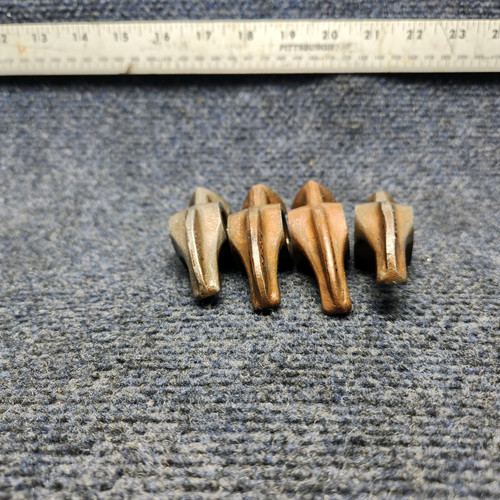
131 CESSNA 172K Skyhawk parts for sale
See all →



Parts listed for sale by vetted eBay sellers — confirmed on eBay at checkout.