Cessna_210_C210M_Centurion...
CESSNA 210 · Pilot's Operating Handbook
Overview
The Cessna T-210 Pilot's Operating Handbook (POH) provides essential information for pilots operating the Cessna T-210 aircraft. It includes detailed specifications, operating procedures, and performance data necessary for safe and efficient flight operations. The handbook is designed for both new and experienced pilots, offering guidance on preflight checks, emergency procedures, and in-flight operations. The POH serves as a critical reference for understanding the aircraft's systems and capabilities, ensuring pilots are well-prepared for various flight scenarios.
- Maximum takeoff weight: 3,600 lbs (1,633 kg)
- Cruise speed: approximately 160 knots
- Range: approximately 800 nautical miles
- Engine: Continental TSIO-520-U, 285 hp
- Takeoff distance at sea level: approximately 1,200 feet
Document
Source
Originally published by www.aeroelectric.com. Sprinkle hosts a reference copy with an added summary, specifications and searchable full text.
Document details
- Type
- Pilot's Operating Handbook
- Pages
- 184
- File size
- 5.7 MB
- Publisher
- www.aeroelectric.com
Specifications & performance
Extracted from this document.
Specifications
- Engine (hp)
- 300
- Length (ft)
- 36
- Propeller
- D3A32C88/82NC-2
- Wingspan (ft)
- 28
- Engine model
- IO-520-L
- Max speed (kt)
- 199
- Empty weight (lb)
- 2,175
- Fuel capacity (gal)
- 90
- Max takeoff weight (lb)
- 3,800
V-speeds
- VA
- 119
- VFE
- 140
- VNE
- 199
- VNO
- 168
Weight & balance
- Baggage allowance (lb)
- 120
- Max landing weight (lb)
- 3,800
- Max takeoff weight (lb)
- 3,800
Common. Rarer than 1% of the aircraft models we track.
Most owners only have the POH. Here's the essential set for the CESSNA 210.
CESSNA 210 for sale now
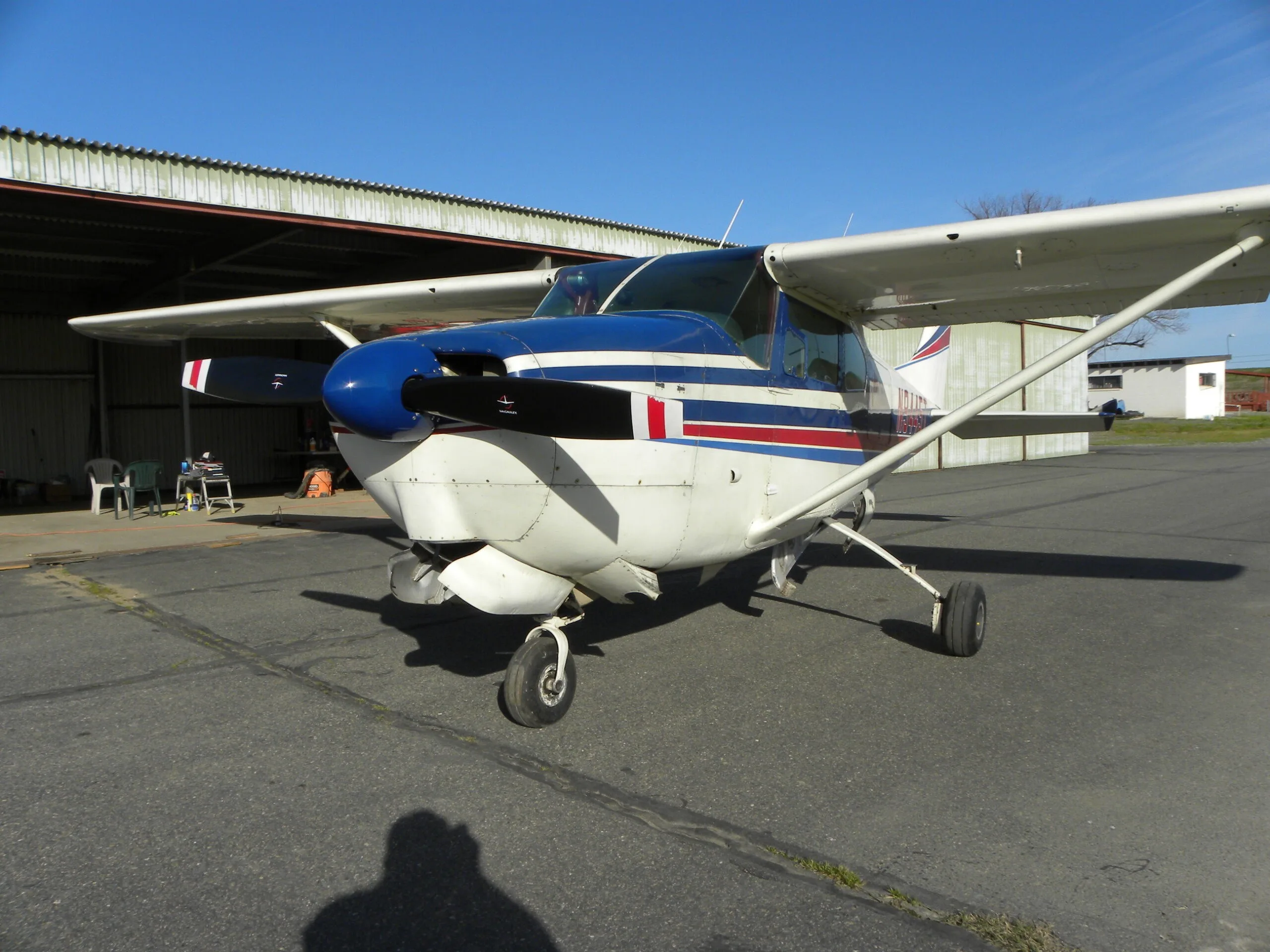


Free — save the 210 to your watchlist and track it in one place.
More CESSNA 210manuals & documents
See all 28 →- Service Bulletin SB-14 - McFarlane AviationService Bulletins
- In-flight break-up involving Cessna 210N, VH-TFTOther Documents
- Fuel starvation involving Cessna T210M, VH-MYWOther Documents
- Engine failure and collision with terrain involving Cessna P210N ...Other Documents
- AIRWORTHINESS BULLETIN Cessna Single Engine Electro-Hydraulic Undercarriage Retraction SystemsService Bulletins
- Request for Legal Interpretation of 14 C.F.R. §§ 91.403(c) and 43.16 Concerning Whether Requirements in an Airworthiness Limitations Section (ALS) Developed By a Design Approval Holder (DAH) and Approved by the Federal Aviation Administration (FAA) as a Change to Type DesignMaintenance Manual
- Backdoor Rulemaking? | Savvy AviationMaintenance Manual
- ATSB Transport Safety ReportOther Documents
- SERVICE LETTER SEL-29-01 Revision 1: Hydraulic Power Pack InspectionWiring Diagram
- cessna-skycatcher-checklist.pdf - Empyrean AeroChecklist
- Airplane Upset Recovery Training Aid Revision 2Training Manual
- Airworthiness Directive AD/CESSNA 210/69 Amdt 2Airworthiness Directives
If you fly the CESSNA 210, you may also be researching these.


In this document
Aircraft Specifications
The Cessna T-210 features a high-wing design with a maximum takeoff weight of 3,600 lbs (1,633 kg) and a useful load of approximately 1,200 lbs (544 kg). It is powered by a Continental TSIO-520-U engine, providing a maximum horsepower of 285 hp. The aircraft has a cruise speed of around 160 knots and a range of approximately 800 nautical miles.
Operating Procedures
This section outlines standard operating procedures for the Cessna T-210, including preflight inspections, engine start procedures, and takeoff and landing protocols. Pilots are advised to perform a thorough preflight inspection, checking fuel levels, control surfaces, and avionics before each flight.
Emergency Procedures
The emergency procedures section provides critical information on handling in-flight emergencies, including engine failure, electrical malfunctions, and cabin depressurization. Pilots should familiarize themselves with these procedures to ensure a prompt and effective response in case of an emergency.
Performance Data
Performance data for the Cessna T-210 includes takeoff and landing distances, climb rates, and fuel consumption rates at various altitudes and weights. For example, the takeoff distance at sea level is approximately 1,200 feet under standard conditions.
Weight and Balance
Proper weight and balance calculations are crucial for safe flight operations. The handbook includes charts and formulas to assist pilots in determining the aircraft's center of gravity and ensuring it remains within safe limits.
Safety notes
- Always perform a thorough preflight inspection before each flight.
- Familiarize yourself with emergency procedures to ensure safety during in-flight emergencies.
- Ensure weight and balance calculations are accurate to maintain safe flight operations.
Full document text
PILOT'S OPERATING HANDBOOK Cessna. D1094-3-13 (RG1-100-8/98) CENTURION 1977 MODEL 210M Serial No. 210 61773 Registration No. VH- MDZ THIS HANDBOOK INCLUDES THE MATERIAL REQUIRED TO BE FURNISHED TO THE PILOT BY CAR PART 3 COPYRIGHT © 1976 CESSNA AIRCRAFT COMPANY WICHITA, KANSAS, USA CHANGE 3 LIST OF EFFECTIVE PAGES CESSNA MODEL 210M INSERT LATEST CHANGED LIST OF EFFECTIVE PAGES PAGES; DISPOSE OF SUPERSEDED PAGES. NOTE: This handbook will be kept current by Service Letters published by Cessna Aircraft Company. These are distributed to Cessna Dealers and to those who subscribe through the Owner Follow-Up System. If you are not receiving subscription service, you will want to keep in touch with your Cessna Dealer for information concerning the change status of the handbook. Subsequent changes should be examined immediately after receipt; the handbook should not be used for operational purposes until it has been updated to a current status. On a changed page, the portion of the text or illustration affected by the change is indicated by a vertical line in the outer margin of the page. Dates of issue for original and changed pages are: Original Change Change Change 15 December 1976 0 1 " 20 August 1976 + . 1 May 1977 3 15 March 1978 THE TOTAL NUMBER OF PAGES IN THIS HANDBOOK IS 356, CONSISTING OF THE FOLLOWING. THIS TOTAL INCLUDES THE SUPPLEMENTS PROVIDED IN SECTION 9 WHICH COVER OPTIONAL SYSTEMS AVAILABLE IN THE AIRPLANE. Page No. #Change No. Page No. #Change No. Title. 3 5-26 Blank 0 A. 3 6-1 0 . i thru iii 0 6-2 Blank iv Blank 0 6-3 thru 6-13 0 1-1 thru 1-8 0 6-14 Blank 12-1 6-15 thru 6-29 2-2 Blank 6-30 Blank • 2-3 thru 2-11 7-1 thru 7-47 2-12 Blank 7-48 Blank 0 3-1 thru 3-11 0 8-1. 0 3-12 Blank 8-2 Blank 3-13 thru 3-21 8-3 thru 8-14 3-22 Blank 9-1 4-1 thru 4-11 9-2 4-12 Blank 4-13 thru 4-22 5-1 5-2 Blank 9-3 5-3 thru 5-14 5-15 5-16 thru 5-25 9-4 Blank Supplements (164 Pages) (Refer to Section 9 Table of Contents for Optional Systems Supplements) COONOON 0 0 0 0 2 # Zero in this column indicates an original page. A Change 3 CESSNA MODEL 210M TABLE OF CONTENTS TABLE OF CONTENTS GENERAL LIMITATIONS EMERGENCY PROCEDURES NORMAL PROCEDURES. PERFORMANCE. SECTION 1 • • 2 • . • • 3 4 • WEIGHT & BALANCE/ EQUIPMENT LIST. . AIRPLANE & SYSTEMS DESCRIPTIONS . . AIRPLANE HANDLING, SERVICE & MAINTENANCE SUPPLEMENTS (Optional Systems Description & Operating Procedures) : 5 6 7 8 NCE.. 9 • iii/(iv blank) SECTION 1 GENERAL 2.2 1.75 1-2 PIVOT POINT 8585 28'-2" 13' 4°7' 3962 CESSNA MODEL 210M 2870 9'-5" MAX. NOTES: 1. Maximum height shown with nose gear depressed, all tires and nose strut properly in- flated and flashing beacon installed. 2. Wheel base length is 72″. 3. Propeller ground clearance is 10 7/8". 4. Wing area is 175 square feet. 5. Minimum turning radius *pivot point to outboard wing tip) is 26'. * * PIVOT POINT 80" MAX. 36'-9" 8' 8" 11202 Figure 1-1. Three View CESSNA MODEL 210M SECTION 1 GENERAL TABLE OF CONTENTS SECTION 1 GENERAL Page Three View Introduction Descriptive Data Engine 1-2 1-3 1-3 1-3 Propeller Fuel 1-3 1-3 Oil . Maximum Certificated Weights Standard Airplane Weights Cabin and Entry Dimensions Baggage Space and Entry Dimensions Specific Loadings 1-4 1-4 1-4 1-5 1-5 1-5 Symbols, Abbreviations and Terminology 1-5 General Airspeed Terminology and Symbols 1-5 Meteorological Terminology. 1-6 Engine Power Terminology 1-6 Airplane Performance and Flight Planning Terminology 1-7 Weight and Balance Terminology. 1-7 1-1 CESSNA MODEL 210M SECTION 1 GENERAL CABIN AND ENTRY DIMENSIONS Detailed dimensions of the cabin interior and entry door openings are illustrated in Section 6. BAGGAGE SPACE AND ENTRY DIMENSIONS Dimensions of the baggage area and baggage door opening are illus- trated in detail in Section 6. SPECIFIC LOADINGS Wing Loading: 21.7 lbs./sq. ft. Power Loading: 12.7 lbs./hp. SYMBOLS, ABBREVIATIONS AND TERMINOLOGY GENERAL AIRSPEED TERMINOLOGY AND SYMBOLS KCAS KIAS KTAS VA VFE VLE VLO Knots Calibrated Airspeed is indicated airspeed corrected for position and instrument error and expressed in knots. Knots calibrated airspeed is equal to KTAS in standard at- mosphere at sea level. Knots Indicated Airspeed is the speed shown on the airspeed indicator and expressed in knots. Knots True Airspeed is the airspeed expressed in knots rel-- ative to undisturbed air which is KCAS corrected for altitude and temperature. Maneuvering Speed is the maximum speed at which you may use abrupt control travel. Maximum Flap Extended Speed is the highest speed permis- sible with wing flaps in a prescribed extended position. Maximum Landing Gear Extended Speed is the maximum speed at which an airplane can be safely flown with the land- ing gear extended. Maximum Landing Gear Operating Speed is the maximum speed at which the landing gear can be safely extended or retracted. 1-5 CESSNA MODEL 210M SECTION 1 GENERAL VNO VNE VS V So Vx Vy Maximum Structural Cruising Speed is the speed that should not be exceeded except in smooth air, then only with caution. Never Exceed Speed is the speed limit that may not be ex- ceeded at any time. Stalling Speed or the minimum steady flight speed at which the airplane is controllable. Stalling Speed or the minimum steady flight speed at which the airplane is controllable in the landing configuration at the most forward center of gravity. Best Angle-of-Climb Speed is the speed which results in the greatest gain of altitude in a given horizontal distance. Best Rate-of-Climb Speed is the speed which results in the greatest gain in altitude in a given time. METEOROLOGICAL TERMINOLOGY ОАТ Standard Tempera- ture Pressure Altitude Outside Air Temperature is the free air static temperature. It is expressed in either degrees Celsius (formerly Centi- grade) or degrees Fahrenheit. Standard Temperature is 15°C at sea level pressure altitude and decreases by 2°C for each 1000 feet of altitude. Pressure Altitude is the altitude read from an altimeter
Show full textShow less
when the altimeter's barometric scale has been set to 29.92 inches of mercury (1013 mb). ENGINE POWER TERMINOLOGY BHP RPM MP 1-6 Brake Horsepower is the power developed by the engine. Percent power values in this handbook are based on the maximum continuous power rating. Revolutions Per Minute is engine speed. Manifold Pressure is a pressure measured in the engine's induction system and is expressed in inches of mercury (Hg). CESSNA MODEL 210M INTRODUCTION SECTION 1 GENERAL This handbook contains 9 sections, and includes the material re- quired to be furnished to the pilot by CAR Part 3. It also contains supple- mental data supplied by Cessna Aircraft Company. Section 1 provides basic data and information of general interest. It also contains definitions or explanations of symbols, abbreviations, and terminology commonly used. DESCRIPTIVE DATA ENGINE Number of Engines: 1. Engine Manufacturer: Teledyne Continental. Engine Model Number: IO-520-L. Engine Type: Normally-aspirated, direct-drive, air-cooled, horizontally- opposed, fuel-injected, six-cylinder engine with 520 cu. in. displacement. Horsepower Rating and Engine Speed: Maximum Power (5 minutes - takeoff): 300 rated BHP at 2850 RPM. Maximum Continuous Power: 285 rated BHP at 2700 RPM. PROPELLER Propeller Manufacturer: McCauley Accessory Division. Propeller Model Number: D3A32C88/82NC-2. Number of Blades: 3. Propeller Diameter, Maximum: 80 inches. Minimum: 78.5 inches. Propeller Type: Constant speed and hydraulically actuated, with a low pitch setting of 11. 5° and a high pitch setting of 28.1° (30 inch station). FUEL Approved Fuel Grades (and Colors): 100LL Grade Aviation Fuel (Blue). 100 (Formerly 100/130) Grade Aviation Fuel (Green). Total Capacity: 90 gallons. Total Capacity Each Tank: 45 gallons. Total Usable: 89 gallons. 1-3 SECTION 1 GENERAL CESSNA MODEL 210M OIL Oil Grade (Specification): MIL-L-6082 Aviation Grade Straight Mineral Oil: Use to replenish supply during first 25 hours and at the first 25-hour oil change. Continue to use until a total of 50 hours has accumulated or oil consumption has stabilized. NOTE The airplane was delivered from the factory with a cor- rosion preventive aircraft engine oil. This oil should be drained after the first 25 hours of operation. Continental Motors Specification MHS-24A, Ashless Dispersant Oil: This oil must be used after first 50 hours or oil consumption has stabilized. Recommended Viscosity For Temperature Range: SAE 50 above 4°C (40°F). SAE 10W30 or SAE 30 below 4°C (40°F). NOTE Multi-viscosity oil with a range of SAE 10W30 is recom- mended for improved starting in cold weather. Oil Capacity: Sump: 10 Quarts. Total: 11 Quarts (if oil filter installed). MAXIMUM CERTIFICATED WEIGHTS Takeoff: 3800 lbs. Landing: 3800 lbs. Weight in Baggage Compartment: Baggage Forward of wheel well on folded down aft seat (Station 89 - to 110): 120 lbs. Baggage On and aft of wheel well (Station 110 to 152): 120 lbs. STANDARD AIRPLANE WEIGHTS Standard Empty Weight, Centurion: 2175 lbs. Centurion II: 2248 lbs. 1625 lbs. Centurion II: 1552 lbs. Maximum Useful Load, Centurion: 1-4 CESSNA MODEL 210M SECTION 1 GENERAL AIRPLANE PERFORMANCE AND FLIGHT PLANNING TERMINOLOGY Demon- strated Crosswind Velocity Demonstrated Crosswind Velocity is the velocity of the cross- wind component for which adequate control of the airplane during takeoff and landing was actually demonstrated during certification tests. The value shown is not considered to be limiting. Usable Fuel Usable Fuel is the fuel available for flight planning. Unusable Fuel РРН NMPG g Unusable Fuel is the quantity of fuel that can not be safely used in flight. Pounds Per Hour is the amount of fuel (in pounds) consumed per hour. Nautical Miles Per Gallon is the distance (in nautical milės) which can be expected per gallon of fuel consumed at a spe- cific engine power setting and/or flight configuration. g is acceleration due to gravity. WEIGHT AND BALANCE TERMINOLOGY Reference Datum Station Arm Moment Center of Gravity (C. G.) C. G. Arm Reference Datum is an imaginary vertical plane from which all horizontal distances are measured for balance purposes. Station is a location along the airplane fuselage given in terms of the distance from the reference datum. Arm is the horizontal distance from the reference datum to the center of gravity (C.G.) of an item. Moment is the product of the weight of an item multiplied by its arm. (Moment divided by the constant 1000 is used in this handbook to simplify balance calculations by reducing the number of digits.) Center of Gravity is the point at which an airplane, or equip- ment, would balance if suspended. Its distance from the ref- erence datum is found by dividing the total moment by the total weight of the airplane. Center of Gravity Arm is the arm obtained by adding the airplane's individual moments and dividing the sum by the total weight. 1-7 SECTION 1 GENERAL CESSNA MODEL 210M C. G. Limits Standard Empty Weight Basic Empty Weight Useful Load Gross (Loaded) Weight Maximum Takeoff Weight Center of Gravity Limits are the extreme center of gravity locations within which the airplane must be operated at a given weight. Standard Empty Weight is the weight of a standard airplane, including unusable fuel, full operating fluids and full engine oil. Basic Empty Weight is the standard empty weight plus the weight of optional equipment. Useful Load is the difference between takeoff weight and the basic empty weight. Gross (Loaded) Weight is the loaded weight of the airplane. Maximum Landing Weight Tare Maximum Takeoff Weight is the maximum weight approved for the start of the takeoff run. Maximum Landing Weight is the maximum weight approved for the landing touchdown. Tare is the weight of chocks, blocks, stands, etc. used when weighing an airplane, and is included in the scale readings. Tare is deducted from the scale reading to obtain the actual (net) airplane weight. 1-8 CESSNA MODEL 210M SECTION 2 LIMITATIONS SECTION 2 LIMITATIONS TABLE OF CONTENTS Page Introduction 2-3 Airspeed Limitations 2-4 Airspeed Indicator Markings 2-4 Power Plant Limitations 2-5 Power Plant Instrument Markings 2-6 Weight Limits . 2-6 Center of Gravity Limits 2-6 Maneuver Limits. 2-7 Flight Load Factor Limits Kinds of Operation Limits. Fuel Limitations Placards 2-7 2-7 2-7 · . 2-8 2-1/(2-2 blank) CESSNA MODEL 210M INTRODUCTION SECTION 2 LIMITATIONS Section 2 includes operating limitations, instrument markings, and basic placards necessary for the safe operation of the airplane, its engine, standard systems and standard equipment. The limitations included in this section have been approved by the Federal Aviation Administration. When applicable, limitations associated with optional systems or equip- ment are included in Section 9. NOTE The airspeeds listed in the Airspeed Limitations chart (figure 2-1) and the Airspeed Indicator Markings chart (figure 2-2) are based on Airspeed Calibration data shown in Section 5 with the normal static source. If the alter- nate static source is being used, ample margins should be observed to allow for the airspeed calibration varia- tions between the normal and alternate static sources as shown in Section 5. Your Cessna is certificated under FAA Type Certificate No. 3A21 as Cessna Model No. 210M. 2-3 SECTION 2 LIMITATIONS AIRSPEED LIMITATIONS CESSNA MODEL 210M Airspeed limitations and their operational significance are shown in figure 2-1. SPEED KCAS KIAS REMARKS VNE Never Exceed Speed 195 199 Do not exceed this speed in any operation. VNO Maximum Structural 165 168 Cruising Speed Do not exceed this speed except in smooth air, and then only with caution. VA Maneuvering Speed: 1720*3800 Pounds 117 119 143 3150 Pounds 107 109 136, 2500 Pounds 95 96 Do not make full or abrupt control movements above this speed. VFE Maximum Flap Extended Speed: To 10° Flaps 138 140 10° - 30° Flaps 105 105 Do not exceed these speeds with the given flap settings. VLO Maximum Landing Gear 138 140 Do not extend or retract Operating Speed landing gear above this speed. VLE Maximum Landing Gear 138 140 Do not exceed this speed Extended Speed with landing gear extended. Maximum Window Open 195 199 Speed Do not exceed this speed with windows open. Figure 2-1. Airspeed Limitations AIRSPEED INDICATOR MARKINGS Airspeed indicator markings and their color code significance are shown in figure 2-2. 2-4 CESSNA MODEL 210M SECTION 2 LIMITATIONS KIAS VALUE MARKING OR RANGE White Arc Green Arc 55-105 68 - 168 Yellow Arc 168 - 199 Red Line 199 SIGNIFICANCE Full Flap Operating Range, Lower limit is maximum weight VS。 in landing configuration. Upper limit is maximum speed permissible with flaps extended. Normal Operating Range. Lower limit is maximum weight Vs at most forward C.G. with flaps retracted. Upper limit is maximum structural cruising speed. Operations must be conducted with caution and only in smooth air. Maximum speed for all operations. Figure 2-2. Airspeed Indicator Markings POWER PLANT LIMITATIONS Engine Manufacturer: Teledyne Continental. Engine Model Number: 10-520-L. Engine Operating Limits for Takeoff and Continuous Operations: Maximum Power, 5 Minutes - Takeoff: 300 BHP. Continuous: 285 BHP. Maximum Engine Speed, 5 Minutes - Takeoff: 2850 RPM. Continuous: 2700 RPM. Maximum Cylinder Head Temperature: 238°C (460°F). Maximum Oil Temperature: 116°C (240°F). Oil Pressure, Minimum: 10 psi. Maximum: 100 psi. Fuel Pressure, Minimum: 3.5 psi. Maximum: 19.5 psi (151 lbs/hr). Propeller Manufacturer: McCauley Accessory Division. Propeller Model Number: D3A32C88/82NC-2. Propeller Diameter, Maximum: 80 inches. Minimum: 78.5 inches. Propeller Blade Angle at 30 Inch Station, Low: 11.5° High: 28.1° 2-5
What's in the CESSNA 210 TCDS
A Type Certificate Data Sheet (TCDS) is the FAA's record of what an aircraft type was approved as. It is the source of truth for weights, seating, fuel and the rules the design was certified against. Expand any line to see what it means.
5,103 CESSNA 210 parts for sale
See all →


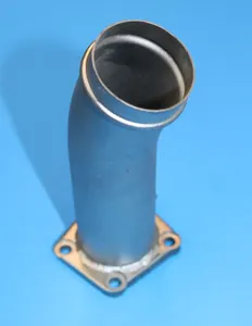
Parts listed for sale by vetted eBay sellers — confirmed on eBay at checkout.