Type Certificate Data Sheet
CESSNA 210N · Type Certificate
Overview
This Type Certificate Data Sheet provides essential information regarding the Cessna 210N aircraft, including its specifications, performance data, and operational limitations. It serves as a reference for pilots, maintenance personnel, and aviation enthusiasts interested in understanding the aircraft's capabilities and requirements. The document outlines critical details such as weight and balance information, V-speeds, and safety notes that are vital for safe operation. It is an authoritative source for compliance with regulatory standards and operational guidelines for the Cessna 210N.
- Wingspan: 36 ft, Length: 27 ft 8 in, Height: 8 ft 10 in
- Empty Weight: 1,650 lbs, Max Takeoff Weight: 3,600 lbs
- Fuel Capacity: 60 gallons
- Stall Speed Clean: 60 knots, Max Crosswind: 15 knots
- VSO: 50 knots, VS1: 60 knots, VR: 70 knots, VX: 75 knots, VY: 85 knots, VNE: 175 knots
Document
Source
Originally published by www.rapcoinc.com. Sprinkle hosts a reference copy with an added summary, specifications and searchable full text.
Document details
- Type
- Type Certificate
- Pages
- 12
- File size
- 357 KB
- Publisher
- www.rapcoinc.com
Specifications & performance
Extracted from this document.
Specifications
- Range (nm)
- 700
- Engine (hp)
- 285
- Height (ft)
- 8.83
- Length (ft)
- 27.67
- Propeller
- McCauley 3-blade
- Wingspan (ft)
- 36
- Engine model
- Continental IO-520-U
- Empty weight (lb)
- 1,650
- Fuel capacity (gal)
- 60
- Rate of climb (fpm)
- 1,000
- Service ceiling (ft)
- 20,000
- Max takeoff weight (lb)
- 3,600
Performance
- Landing distance (ft)
- 1,200
- Takeoff distance (ft)
- 1,500
Weight & balance
- Useful load (lb)
- 1,950
- Max ramp weight (lb)
- 3,600
- Baggage allowance (lb)
- 200
- Basic empty weight (lb)
- 1,650
- Max takeoff weight (lb)
- 3,600
Common. One of the most common aircraft types we track.
Most owners only have the POH. Here's the essential set for the CESSNA 210N.
- Pilot's Operating Handbook / AFM
- Checklist
- Maintenance Manual
- Parts Catalog (IPC)
- Systems & Wiring
- Service Bulletins
- Type Certificate (TCDS)
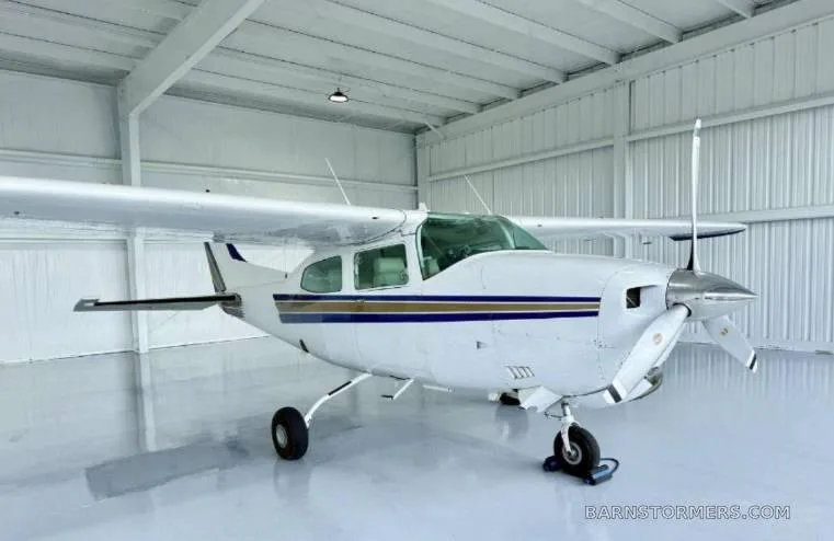
CESSNA 210N for sale now
Free — save the 210N to your watchlist and track it in one place.
More CESSNA 210Nmanuals & documents
See all 13 →- CHECKLISTS - Aircraft SpruceChecklist
- CHECKMATE CHECKLISTS - Aircraft SpruceChecklist
- SERVICE TABLE OF LIMITS AND TORQUE VALUE RECOMMENDATIONSV Speeds Reference
- Loading SummaryWeight And Balance
- B&C Standby Alternator System for the Cessna 210Wiring Diagram
- Wheels up landing involving Cessna 210, VH-UPNOther Documents
- CAP – Cessna Short- and Soft-Field OperationsChecklist
- TYPE ACCEPTANCE CERTIFICATEType Certificate
- EASA STC no. STC holderTraining Manual
- SCHEDULE OF AIRWORTHINESS DIRECTIVESAirworthiness Directives
- Interior Maintenance Manual Illustrated Parts Catalog Model 750Parts Catalog
- Cessna T210N - AirMartSpecifications
If you fly the CESSNA 210N, you may also be researching these.


In this document
Aircraft Specifications
The Cessna 210N features a wingspan of 36 feet, 0 inches, a length of 27 feet, 8 inches, and a height of 8 feet, 10 inches. The empty weight is approximately 1,650 lbs, while the maximum takeoff weight is 3,600 lbs. The fuel capacity is 60 gallons.
Performance Data
The performance data for the Cessna 210N includes a takeoff distance of 1,500 feet and a landing distance of 1,200 feet. The stall speed in a clean configuration is 60 knots, and the maximum crosswind component is 15 knots.
Weight and Balance
The basic empty weight of the Cessna 210N is 1,650 lbs, with a maximum ramp weight of 3,600 lbs. The useful load is 1,950 lbs, and the baggage allowance is 200 lbs. The center of gravity range is from 36 to 46 inches.
V-Speeds
Key V-speeds for the Cessna 210N include VSO at 50 knots, VS1 at 60 knots, VR at 70 knots, VX at 75 knots, and VY at 85 knots. The maximum speed (VNE) is 175 knots.
Safety notes
- Ensure weight and balance calculations are performed before flight.
- Adhere to maximum crosswind limits during takeoff and landing.
Full document text
United States of America Department of Transportation -- Federal Aviation Administration Supplemental Type Certificate Number This certificate issued to Aero Cables Corp. 11953 S. Spaulding School Road Unit 2 Plainfield, IL 60544 SA791GL certifies that the change in the type design for the following product with the limitations and conditions therefor as specified hereon meets the airworthiness requirements of Part 3 of the Civil Air Regulations. (See Type Certificate Data Sheet A4CE for complete certification basis.) Original Product Type Certificate Number: A4CE Make: Model: Description of Type Design Change: Cessna Aircraft Company 206, P206, P206A, P206B, P206C, P206D, P206E, U206, U206A, U206B, U206C, U206D, U206E, U206F, U206G, TP206A, TP206B, TP206C, TP206D, TP206E, TU206A, TU206B, TU206C, TU206D, TU206E. TU206F. TU206G Installation of a Cooling Shroud on engine driven dry air pumps in accordance with S & M Products Report No. 4, Revision 00 dated May 7, 1984, or subsequent FAA approved revision. Limitations and Conditions : 1) Compatibility of this design change with previously approved modifications must be determined by the installer. 2) If the holder agrees to permit another person to use this certificate to alter the product, the holder shall give the other person written evidence of that permission. This certificate and the supporting data which is the basis for approval shall remain in effect until surrendered, suspended, revoked or a termination date is otherwise established by the Administrator of the Federal Aviation Administration. Date reissued March 19, 2004; June 15, 2004 Date of application. May 7, 1984 Date of issuance June 18, 1984 FEDERAL AVIATION * Dale amended: By direction of the Administrator Gay for Charles E. Smalley 7 (Signature -Manager, Systems and Flight Test Branch Chicago Aircraft Certification Office (Title) TOMINISTRATION Any alteration of this certificate is punishable by a fine of not exceeding $1,000, or imprisonment not exceeding 3 years, or both. 船 - KIT NO. 10 KIT NO. 11 - S&M Report No. 4 Revision Ol March 7, 1985 Vacuum Pump Cooling Kit for Airborne Model 200 thru 212CW and CC Dry Air Pumps Vacuum Pump Cooling Kit for EDO-AIRE Model 1U128, 1U128A and 1U128B; and SIGMA TEK Model 1U128B Dry Air Pumps Cessna 206, P206, P206A thru P206E, U206, U206A thru U206G, TP206, TP206A thru TP206E, TU206A thru TU206G, TC A4CE REVISION PAGE Table of Contents Revision Page Page No. Revision/Date 1 01, 03-07-85 Kit No. 10 and Kit No. 11 Parts List 2 01, 03-07-85 Drawing List for Kit No. 10 and Kit No. 11 3 01, 03-07-85 Installation Instructions 4 & 5 01, 03-07-85 STC and Eligibility Listing 6 01, 03-07-85 Drawing H (Cessna 206 Series (all models thru 1973) and Cessna U206 Series (1974 to present)) 7 00, 05-07-84 Drawing J (Cessna U206F and U206G) 7 00, 05-07-84 Drawing K (Cessna T206F and T206G) 7 00, 05-07-84 Drawing L (Cessna T206F and T206G) 7 00, 05-07-84 Drawing Q (View of Cooling Kit on Airborne Pump) 8 00, 05-07-84 Drawing R (View of Cooling Kit on EDO-AIRE and SIGMA TEK Pumps) 9 01, 03-07-85 Material Specifications 10 01, 03-07-85 Drawing, Cooling Shroud Model 2CDH 11 00, 05-07-84 Drawing, Cooling Shroud Model 4ADH 12 01, 03-07-85 FAA APPROVED MAR 15 1985 CHICAGO AIRCRAFT CERTIFICATION OFFICE CENTRAL REGION ACE 130 C no KIT NO. 10 KIT NO. 11 - S&M Report No. 4 Revision 01 March 7, 1985 Vacuum Pump Cooling Kit for Airborne Model 200 thru 212CW and CC Dry Air Pumps Vacuum Pump Cooling Kit for EDO-AIRE Model lU128, 1U128A and 1U128B; and SIGMA TEK Model 1U128B Dry Air Pumps Cessna 206, P206, P206A thru P206E, U206, U206A thru U206G, TP206, TP206A thru TP206E, TU206A thru TU206G, TC A4CE KIT NO. 10 PARTS LIST AIRBORNE INSTALLATION Quantity Part No. 1 2CDH 1 2CDH-1 1 2CDH-2 2 2CDH-3 1 Rev. 01, 03-07-85 1 Rev. 00, 05-07-84 1 Rev. 00, 05-07-84 1 Rev. 01, 03-07-85 Description Cooling Shroud Flange Approx 13.3" C.A.T. Aeroduct Tubing Cable Ties Installation Instructions Flange Installation Drawings Kit Installation Drawing (View of Cooling Kit on Pump) STC and Eligibility Listing KIT NO. 11 PARTS LIST - EDO-AIRE & SIGMA TEK INSTALLATION Description Cooling Shroud Flange Approx 17" C.A.T. Aeroduct Tubing Cable Ties Installation Instructions Flange Installation Drawings Kit Installation Drawing (View of Cooling Kit on Pump) STC and Eligibility Listing Quantity Part No. 1 4ADH 1 4ADH-1 1 4ADH-2 2 4ADH-3 1 Rev. 01, 03-07-85 1 Rev. 00, 05-07-84 1 Rev. 01, 03-07-85 1 Rev. 01, 03-07-85 KIT NO. 10 KIT NO. 11 - S&M Report No. 4 Revision 01 March 7, 1985 Vacuum Pump Cooling Kit for Airborne Model 200 thru 212CW and CC Dry Air Pumps Vacuum Pump Cooling Kit for EDO-AIRE Model 1U128, 1U128A and 1U128B; and SIGMA TEK Model lU128B Dry Air Pumps Cessna 206, P206, P206A thru P206E, U206, U206A thru U206G, TP206, TP206A thru TP206E, TU206A thru TU206G, TC A4CE DRAWING LIST FOR KIT NO. 10 & KIT NO. 11 Drawing Description Page No. H CESSNA 206 Series (all models thru 1973) and CESSNA U206 Series (1974 to present) Flange installation location and measurements (L H View, for AIRBORNE Pumps only). 7 J - CESSNA U206F and U206G Flange installation location and measurements (R H View). 7 K CESSNA T206F and T206G Flange installation location and measurements (L H View, for AIRBORNE Pumps Only). 7 L CESSNA T206F and T206G Flange installation location and measurements (R H View). - 7 10 View of Cooling Shroud on AIRBORNE Pump, Ducting and Flange (KIT NO. 10). 8 R View of Cooling Shroud on EDO-AIRE and SIGMA TEK Pumps, Ducting and Flange (KIT NO. 11). 9 ว KIT NO. 10 KIT NO. 11 - S&M Report No. 4 Revision 01 March 7, 1985 Vacuum Pump Cooling Kit for Airborne Model 200 thru 212CW and CC Dry Air Pumps Vacuum Pump Cooling Kit for EDO-AIRE Model 1U128, 1U128A and 1U128B; and SIGMA TEK Model lU128B Dry Air Pumps Cessna 206, P206, P206A thru P206E, U206, U206A thru U206G, TP206, TP206A thru TP206E, TU206A thru TU206G, TC A4CE INSTALLATION INSTRUCTIONS
Show full textShow less
1. To install Vacuum Pump Cooling Kit No. 10 on Airborne Model 200 thru 212CW and CC Dry Air Pumps, or Vacuum Pump Cooling Kit No. 11 on EDO-AIRE Model 1U128, 1U128A, 1U128B, and SIGMA TEK Model 1U128B Dry Air Pumps installed on the aircraft shown above, proceed according to the following instructions and refer to Flange Installation Drawings H, J, K, and L. For a view of the cooling shroud, ducting and flange, refer to Drawing Q for Kit No. 10 and Drawing R for Kit No. 11. 2. COOLING SHROUD INSTALLATION. a. To mount the cooling shroud on the vacuum pump, the shroud must be held open slightly while installing. The shroud is made so the cooling exit is not centered with the cooling inlet. Turn over and/or rotate the shroud on the vacuum pump to best compromise the cooling inlet and outlet with other objects that may interfere with them near and around the vacuum pump. b. On the Airborne installation (Kit No. 10), the shroud may not be able to be slipped on the pump and rotated to the desired position because of interference with other parts. In this case, remove the rear fitting on the pump, slip the shroud on and rotate it, then reinstall the rear fitting. If lubrication of the fitting is needed, use only a spray silicone on the threads, shake off the excess and let it dry before installing the fitting. DO NOT use oil, grease or tape on the threads. C. Optional Shroud Position on Lycoming Engines. Due to tachometer drive interference on some Lycoming engines, an optional position on the shroud may be 1/8" toward the undriven end of the pump, or the shroud can be filed to allow the shroud to center on the pump. DO NOT file through the shroud. 3. COOLING DUCT INSTALLATION. Install the cooling duct on the shroud inlet using sealant and a nylon cable tie, as per instructions on Drawing Q or R, as applicable. Route the cooling duct to the aft side of the rear engine baffle, avoiding sharp bends, sharp objects and moving parts. Do not cut off excess duct at this time. 4. INSTALLATION OF FLANGE FITTING. (Refer to Drawings H, J, K or L) a. Make a 1 1/8" hole in the baffle, maintaining a 1" edge distance minimum, or as per drawing. b. Drill four (4) %2340 holes and use washers under rivets on flange side. Install the flange through the baffle from the front. Use sealant between flange and baffle. Install the flanged fitting using four (4) AN470AD-3 rivets or drill four (4) #28 holes and use four (4) AN526-632 screws and AN365-632 nuts and AN960-6 washers. S&M Report No. 4 Revision 01 March 7, 1985 Installation Instructions (Continued): C. Cut the cooling duct to length--avoid making it too long or too short for best routing. Try to avoid making over 90 degree bends and sharp bends. d. Install the cooling duct on the flanged fitting using sealant and a nylon cable tie (See Drawing Q or R). Support or tie the cooling duct every 12 inches. 5. SEALING REQUIREMENTS. a. To compensate for the 7/8" hole in the rear engine baffle, seal holes in the engine baffling at forward and rear corners, the space between the rear baffle and the engine crankcase, where sheet metal corners have holes in them, and where hoses and wires pass through the baffling. Seal enough holes and gaps to exceed .601 square inch, or 1/8" x 5", or 1/4" x 2.5". b. Use 890 or RTV 106 red high temperature sealants per manufacturers' instructions. Alternate sealants are GE RTV 102, 103, 108, 158; Dow Corning 732 RTV sealants; or equivalents. 6. PAPERWORK. a. Add the appropriate cooling kit number to the aircraft equipment list. b. Weight of this kit is .24 lbs. C. Complete FAA Form 337 and make proper logbook entry of kit installation. 10 5 KIT NO. 10 KIT NO. 11 - S&M Report No. 4 Revision 01 March 7, 1985 Vacuum Pump Cooling Kit for Airborne Model 200 thru 212CW and CC Dry Air Pumps Vacuum Pump Cooling Kit for EDO-AIRE Model 1U128, 1U128A and 1U128B; and SIGMA TEK Model lU128B Dry Air Pumps TC Number STC Number 3A12 SA 702GL STC AND ELIGIBILITY LISTING Eligibility CESSNA 172K, 172L, 172M, 172N, 172P, 172Q CESSNA 182G, 182H, 182J, 182K, 182L, 182M, 182N, 182P, 182Q, R182, TR182, T182 CESSNA T210M, T21ON 3A13 SA 777GL 3A21 SA 785GL 210L, 210M, 210N, T210L, A4CE SA 791GL CESSNA 206, P206, P206A, P206C, P206D, P206E, U206, P206B, U206A, U206B, U206C, U206D, U206E, U206G, TP206A, U206F, TP206B, TP206C, TP206D, TP206E, TU206A, TU206B, TU206C, TU206D, TU206E, TU206F, TU206G FLANGE INSTALLATION DRAWINGS S&M Report No. 4 Revision 00 May 7, 1984 Drawing H (AIRBORNE PUMP ONLY) Left Hand Drive Pad SSNA 206 Series, all models, TC A4CE (thru del year 1973) and CESSNA U206 Series, TC .CE (model year 1974 to present) ISSNA 210L, 210M, 210N TC 3421 О -11/8" hole. centered as shown Drawing J Right Hand Drive Pad CESSNA U206F and U206G, TC A4CE CESSNA 210N TC3A21 О .1 1/8* hole iew: LH rear engine baffle, looking forward Drawing FAA APPROVED Low: JUN 18 1984 CHICAGO AIRCRAFT CERTIFICATION OFFICE CENTRAL REGION AGE 1300 PUMP ONLY) MicDabl K (AIRBORNE Left Hand Drive Pad CESSNA T210L, T210M, T210N TC3A21 CESSNA T206F, T206G TC ALCE RH rear engine baffle, looking forward Drawing L Right Hand Drive Pad CESSNA T210L, T210M, T210N CESSNA T206F, T206G TC AĘCE TC 3421 1 1/8" hole О -2° Viewi LH rear engine baffle, looking forward View: 2" 1 1/8 hole RH rear engine baffle, looking forward 6A2528GL- 17 4 5 S&M Report No. 4 Revision 00 May 7, 1984 KIT NO. 10 View of Cooling Shroud on AIRBORNE Pump, Ducting & Flange 5 5 Cooling Shroud Ducting Flange 3 Note: Shroud must be centered on the pump. - Cable Ties Attach these around ducting at inlet of shroud and outlet of flange after ducting has been sealed into place on the inlet and outlet. Sealant Place sealant on outside of shroud inlet and flange outlet, then push ducting into place. For type of sealant to be used, refer to paragraph 5b of Installation Instructions. FAA APPROVED JUN 18 1984 CHICAGO AIRCRAFT CERTIFICATION OFFICE CENTRAL REGION ACE 130C ткрове 5 AR Sealant 4 2 3 A/R Cable Ties [2CDH-: Ducting 2CDH- 2 1 Flange 2CDH- 1 Shroud 2CDH Drawing Q Item Qty Nomenclature: Part S&M PRODUCTS 2515 E. Bonnie Brook La Waukegan, IL 60087 Rev. 00 Date: 05-07-81 = 5 KIT NO. 11 S&M Report No. 4 Revision 01 March 7, 1985 View of Cooling Shroud on EDO-AIRE & SIGMA TEK Pumps, Ducting & Flange Cooling Shroud 4 Note: 1 5 5 3 Ducting 4 5 2 Flange Shroud must be centered on the pump. On some installations the pump may have to be rotated on the mounting pad because of interference with other objects. Cable Ties - Attach these around ducting at inlet of shroud and outlet of flange after ducting has been sealed into place on the inlet and outlet. - Sealant Place sealant on outside of shroud inlet and flange outlet, then DRAWING R 5 5 push ducting into place. sealant to be used, refer to paragraph 5b of Installation Instructions. For type of A/R A/R Sealant 4 2 Cable Ties 4ADH-3 3 A/R Ducting 4ADH-2 2. 1 Flange 4ADH-1 1 1 Shroud 4ADH 5 Apply sealant fillet between shroud and pump, at the rear of the pump, as shown, to prevent shifting of shroud on pump. Item Qty Nomenclature Part No. S&M PRODUCTS 2515 E. Bonnie Brook Lane Waukegan, IL 60087 Rev. 01 Date: 03-07-85
What's in the CESSNA 210N TCDS
A Type Certificate Data Sheet (TCDS) is the FAA's record of what an aircraft type was approved as. It is the source of truth for weights, seating, fuel and the rules the design was certified against. Expand any line to see what it means.
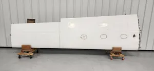
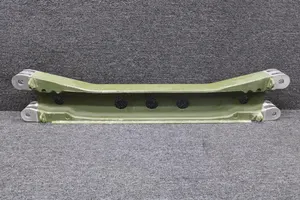
64 CESSNA 210N parts for sale
See all →

Parts listed for sale by vetted eBay sellers — confirmed on eBay at checkout.