AAIB Bulletin: 8/2016
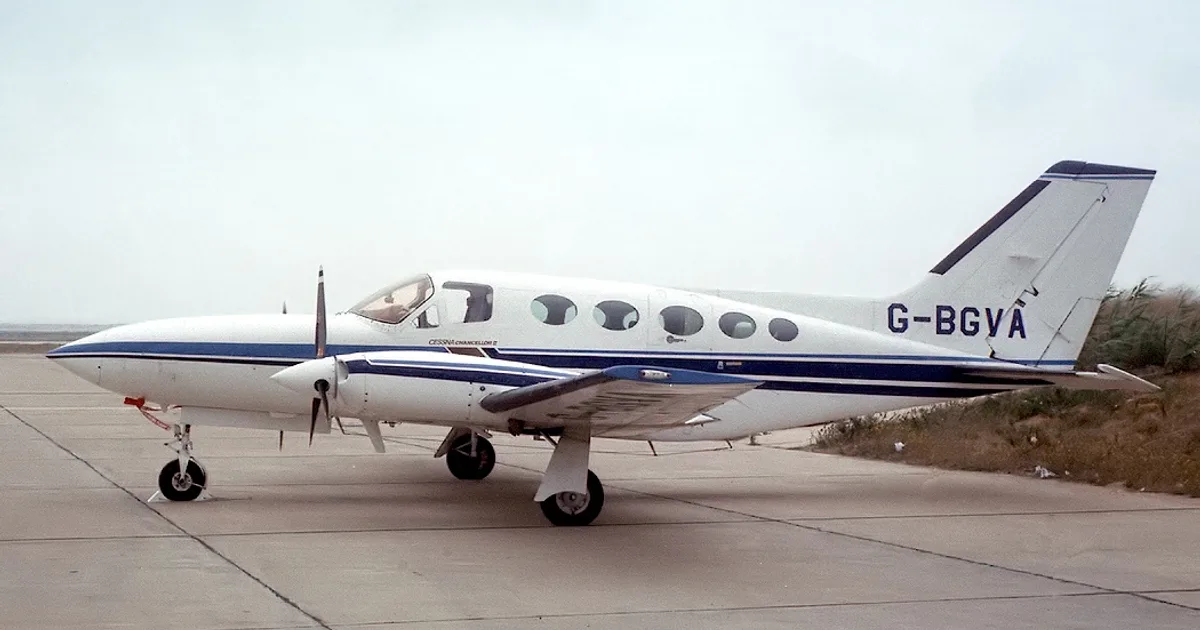
Cessna 402 · Other Documents
Overview
This document is an accident report concerning the Cessna 402B aircraft, specifically registration G-MAPP. It details an incident that occurred on January 14, 2016, during a training flight at East Midlands Airport, where the left main landing gear collapsed during landing. The report includes a thorough analysis of the accident, including the aircraft's specifications, the sequence of events leading to the incident, and the subsequent investigation findings. It highlights the probable cause of the landing gear failure, which was linked to the incorrect fitment of a set screw in the downlock link. The report also includes safety recommendations to prevent similar occurrences in the future.
- Aircraft model: Cessna 402B
- Maximum landing weight: 6,300 lb
- Estimated landing weight at accident: 5,700 lb
- Probable cause of accident: Incorrect fitment of set screw in downlock link
- Tensile strength of pivot bolt: 160 to 180 ksi
- Safety recommendation issued to improve maintenance procedures
Document
Source
Originally published by assets.publishing.service.gov.uk. Sprinkle hosts a reference copy with an added summary, specifications and searchable full text.
Document details
- Type
- Other Documents
- Year
- 2016
- Pages
- 9
- File size
- 397 KB
- Publisher
- assets.publishing.service.gov.uk
Common. Rarer than 6% of the aircraft models we track.
Most owners only have the POH. Here's the essential set for the Cessna 402.
- Pilot's Operating Handbook / AFM
- Checklist
- Maintenance Manual
- Parts Catalog (IPC)
- Systems & Wiring
- Service Bulletins
- Type Certificate (TCDS)
Free — save the 402 to your watchlist and track it in one place.
More Cessna 402manuals & documents
If you fly the Cessna 402, you may also be researching these.




In this document
Aircraft Information
The Cessna 402B is a twin-engine aircraft with a maximum certificated landing weight of 6,300 lb. At the time of the accident, the estimated landing weight was approximately 5,700 lb. The aircraft features a retractable tricycle landing gear system powered by an electric motor.
Accident Synopsis
During the landing roll, the left main landing gear collapsed, causing the aircraft to veer off the runway. The left wing and propeller sustained damage as a result. The incident was attributed to the incorrect installation of a set screw in the downlock link.
Metallurgical Analysis
The investigation included a metallurgical analysis of the pivot bolt and bellcrank components. It was determined that the failure was due to overload with no pre-existing cracks. The pivot bolt had a tensile strength of 160 to 180 ksi.
Safety Actions
Following the accident, the operator implemented a fleet check to ensure proper installation of the set screws in the downlock links of their aircraft. A new procedure was introduced to verify the security of the set screw and downlock pin.
Safety Recommendation
The report recommends that Textron Aviation inform operators of Cessna 300 and 400-series aircraft about the necessary actions to ensure proper installation of the set screw retaining the main gear downlock pin.
Safety notes
- Ensure proper installation of the set screw in the downlock link to prevent landing gear failure.
Full document text
9 ©Crown copyright 2016 AAIB Bulletin: 8/2016 AAIB Bulletin: 8/2016 G-MAPP EW/C2016/01/01 ACCIDENT Aircraft Type and Registration: Cessna 402B, G-MAPP No & Type of Engines: 2 x Continental Motors Corp TSIO-520-EB piston engines Year of Manufacture: 1974 (Serial no: 402B-0583) Date & Time (UTC): 14 January 2016 at 1214 hrs Location: East Midlands Airport Type of Flight: Training Persons on Board: Crew - 2 Passengers - 1 Injuries: Crew - None Passengers - None Nature of Damage: Damage to the left main landing gear, left wingtip and aileron, and blade tips of the left propeller. Left engine shock-loaded Commander’s Licence: Commercial Pilot’s Licence Commander’s Age: 39 years Commander’s Flying Experience: 3,900 hours (of which 2,800 were on type) Last 90 days - 38 hours Last 28 days - 11 hours Information Source: AAIB Field Investigation Synopsis During the landing roll the aircraft’s left main landing gear collapsed and the aircraft departed the left side of the paved runway. The damaged sustained by the left landing gear components was consistent with the side brace folding as weight was transferred onto the landing gear during the landing. The cause of the landing gear collapse was most probably the incorrect fitment of a set screw in the downlock link. One Safety Recommendation is made. History of the flight At 1141 hrs, G-MAPP took off from Runway 27 at East Midlands Airport. On board was an instructor, and two pilots who had recently joined the operator, who were learning to fly this aircraft type. This was the second conversion flight for the new joiners; one was occupying the left pilot’s seat, and the other sat in the cabin to observe his colleague. The instructor occupied the right pilot’s seat. The weather conditions were good, and the crosswind component of the wind, at 11 kt, was within the company limit of 16 kt for this aircraft type. The aircraft flew two approaches to overshoot and two touch-and-gos, before taking off again, prior to its fifth approach. For this fifth approach the instructor planned to 10 ©Crown copyright 2016 AAIB Bulletin: 8/2016 AAIB Bulletin: 8/2016 G-MAPP EW/C2016/01/01 demonstrate a flapless approach to a full stop landing. The VREF was calculated as 108 kt and an uneventful approach was flown, with the landing gear confirmed as indicating fully down by all on board, to a landing which was described as smooth. After landing, as the aircraft was slowing down, the left wing began to sink and the left propeller made contact with the ground. The instructor made a MAYDAY call but was unable to keep the aircraft on the runway, and it came to rest on the grass just to the south of the runway, west of intersection ‘S’. The instructor made the aircraft safe and the crew, who were uninjured, evacuated the aircraft. Taxiway ‘S’ is located close to the fire station and fire crews were quickly on scene, but there was no fire. Aircraft information The Cessna 402B is a twin-engined aircraft equipped with a retractable, tricycle landing gear. The aircraft has a maximum certificated landing weight of 6,300 lb and the estimated landing weight at the time of the accident was approximately 5,700 lb, with the centre of gravity within permitted limits. The landing gear retraction system is powered by an electric motor that drives, via a reduction gearbox, a series of rods, torque-tubes and bellcranks that move the landing gear legs. The main landing gear is held in the ‘down and locked’ position by a folding side brace. A downlock link, driven by a bellcrank, applies a force to the side brace to keep it in an over-centre position when the landing gear is down, Figure 1. Figure 1 Schematic of the landing gear downlock mechanism 11 ©Crown copyright 2016 AAIB Bulletin: 8/2016 AAIB Bulletin: 8/2016 G-MAPP EW/C2016/01/01 When the main landing gear leg is down and locked, the downlock link and bellcrank should be in an over-centre position, to hold the side brace over-centre and prevent it from folding. A microswitch, mounted on the downlock link, closes when it is over-centre and illuminates the green down instrument panel light for that landing gear leg. The bellcrank is connected to the downlock link by a pin, which is secured in place by a set screw. To ensure that the screw engages in the detent in the pin, an arrow, which is stamped in the end of the downlock pin, must be aligned with the set screw, Figure 2. Downlock Pin Downlock Pin Set screw Downlock link Bellcrank Figure 2 Downlock pin and set screw Aircraft damage General The damage to the left wing and propeller blades was consistent with the left landing gear collapsing and the wing rubbing along the runway. The left landing lamp had been torn out of its mounting and the skin on the lower surface of the wingtip and the outer section of the left aileron had been heavily abraded. All three blade tips on the left propeller had bent rearwards with the outer 20 cm of the blades heavily abraded. Left landing main landing gear On the left landing gear, the head of the bellcrank pivot bolt was missing and the remainder of the bolt, which was still attached to the bellcrank, had moved forwards out of the aft mounting lug. The forward mounting lug had fractured across the bolt hole. The Airport Fire Service (AFS) recovered the outer section of the forward lug from the runway, Figure 3. The downlock pin and its associated bushes were missing. The forward lower lug on the bellcrank had fractured and was recovered from the runway by the AFS. The bolt hole on the rear lower lug, which remained attached to the bellcrank, was damaged. The spring which holds the downlock link in the over-centre position was still attached to the landing gear leg and the downlock link, Figure 4. 12 ©Crown copyright 2016 AAIB Bulletin: 8/2016 AAIB Bulletin: 8/2016 G-MAPP EW/C2016/01/01 Aft lug Forward lug Remaining section of pivot bolt Figure 3 Pivot bolt and mounting lugs Bell crank Missing pin Forward lug Figure 4
Show full textShow less
Downlock link 13 ©Crown copyright 2016 AAIB Bulletin: 8/2016 AAIB Bulletin: 8/2016 G-MAPP EW/C2016/01/01 Metallurgical analysis The fracture surfaces on the pivot bolt and the lugs on the bellcrank and landing gear were inspected by a metallurgist, who advised that the surfaces showed no evidence of a pre-existing crack and had all failed in overload. The lower forward lug had failed as a result of the lug bending forwards. The part number of the pivot bolt identified it as an aerospace shear bolt with a tensile strength of 160 to 180 ksi, which equates to a Vickers hardness of 352 to 397 HV. A test carried out on the remaining section of the pivot bolt fitted to the left bellcrank on G-MAPP established its hardness as approximately 380 HV. This is within the specified hardness range for the bolt. Examination of downlock link Examination of the downlock link revealed that the end fitting that connects to the lower side brace had rotated clockwise by approximately 45º, Figure 5. The set screw was still wire locked to the casting and the head of the screw sat proud of the casting by 4 mm, with approximately five threads showing (Item A). The end of the set screw was flush with the wall of the bore in the casting and did not appear to have entered the hole in the bush. The bush had circumferential damage approximately 4 to 5 mm from the forward face of the downlock. The aft face of the downlock was undamaged, whereas the bore where it exited the forward face of the casting was distorted. Figure 5 Downlock link Bush A B Damage End fitting rotated by 45. 14 ©Crown copyright 2016 AAIB Bulletin: 8/2016 AAIB Bulletin: 8/2016 G-MAPP EW/C2016/01/01 A comparison was made between a number of the key measurements on the left and right downlock links fitted to G-MAPP. Refer to Figure 5 and Table 1. Left downlock link Right downlock link Height of head of set screw above casting (A) 4 mm (approx 5 threads) 4 mm (approx 5 threads) Length of threaded portion of set screw 16.4 mm 17.2 mm Depth of casting (B) 12.6 mm 11.9 mm Table 1 Comparison of key measurements on downlock links The measurements showed that with the head of the set screw 4 mm above the casting, the right downlock pin would have been locked in place, whereas the left downlock pin would have been free to move. The height of the set screws was checked on one of the operator’s Cessna 310R aircraft where the clearance between the head of the screw and the casting was found to be approximately 2 mm (two threads). It was noticed when refitting the downlock pin into the right downlock link / bellcrank assembly that it was a tight fit and had to be tapped into position with a hammer. The operator’s engineers advised that this is quite normal. It was also noted that the set screw was easy to insert into the downlock link until the end of the screw reached the bush, when a significant increase in torque was required to turn the screw as it passed into the bush. Prior to the removal of the right downlock link, carried out as part of this investigation, the rigging of the right main landing gear was checked and found to be satisfactory. Manufacturer’s instructions on fitting the downlock pin Aircraft maintenance manual The installation, rigging and functional testing of the main landing gear is detailed in Chapter 4-18 to Chapter 4-32 of the Cessna 401/402 Service Manual. Chapter 4-26 (c) refers to the set screw and states: ‘c. Install uplock assembly as follows: 1. Assemble side brace lock link (42) to bellcrank (35) with pin (36). On aircraft 401-0001 and On and 402-0001 to 402B1090, secure set screw (41) and stake. Do not stake over existing stakes. On aircraft 402B1090 and On, safety wire set screw to side brace. NOTE Ensure arrow (indicating flat surface) located on end of pin is aligned towards set screw.’ 15 ©Crown copyright 2016 AAIB Bulletin: 8/2016 AAIB Bulletin: 8/2016 G-MAPP EW/C2016/01/01 The 401/402 Service Manual makes no mention of ensuring that that the set screw is inserted a sufficient distance to secure the downlock pin. Service Letter On 23 January 1976, the Cessna Aircraft Company issued a Service Letter1 instructing operators of Cessna 300 and 400 series of aircraft to carry out an inspection within the next 200 hours of operation to ensure that the set screw, which retains the main landing gear downlock link, is properly installed. While this Service Letter is still available, there is no repeat inspection criteria and it has not been included in Section 02 of the Aircraft Maintenance Manual as a scheduled inspection task to be incorporated in the Aircraft Maintenance Programme. Some of the instructions in the Service Letter are also outdated. The instruction refers to ‘staking 2 ’ the set screw, which on G-MAPP was secured by wire locking, and identifies the set screw as Part Number AN565D8H8, which is different to the Cessna 402B IPC which refers to Part Number MS35265-46. Significant maintenance The aircraft had undergone its annual maintenance during May 2015 during which the left main landing gear leg was removed for non-destructive inspections. During this activity the bellcrank pivot bolt, downlock link spring and the bolt securing the lower side brace to the leg were removed. However, neither the set screw nor the downlock pin were disturbed. On assembling the landing gear the left pivot pin was replaced with a new item and rigging and functional checks were carried out by an experienced licensed aircraft engineer in accordance with the relevant chapters of the Aircraft Maintenance Manual 3 . The accident occurred 90 cycles and 117 flying hours after the annual maintenance. On 22 December 2015, a 50-hour inspection was carried out during which the main landing gear was visually inspected. There were no reports of any faults or maintenance having been carried out on the landing gear. The accident occurred 19 cycles and 13 flying hours later. It was not possible to establish when the downlock pin on G-MAPP was last disturbed. The operator’s records show that since 2011 five downlock pins have been issued to their fleet of seven Cessna 300 and 400 aircraft; however, none had been issued against G-MAPP. The operator stated that downlock pins were normally replaced due to corrosion or play in the linkage. Footnote 1 Cessna Aircraft Company Service Letter ME76-4, dated January 23, 1976. Subject: Main landing gear down lock pin and set screw inspection. 2 Staking is where a centre-punch is used to drive some of the material from the casting into the thread of the set screw to lock it in place. 3 Cessna 401/402 Service Manual Chapter 4-18 to 4-32. 16 ©Crown copyright 2016 AAIB Bulletin: 8/2016 AAIB Bulletin: 8/2016 G-MAPP EW/C2016/01/01 Analysis The aircraft was within its maximum landing weight and there was no damage to the airframe to indicate that it had been subject to a hard landing. From the damage to the components on the left main landing gear it is probable that the side brace was not geometrically over centre during the ground roll. An inboard side-load force on the main wheel, such as might have occurred during the crosswind landing, would have caused the side brace to begin to fold, leading to the observed overload failure of the pivot bolt and bellcrank mounting lugs. There are three possible reasons why the left main landing gear side brace may not have been over centre: the landing gear may have been incorrectly rigged; a component may have failed; or the downlock pin was not secured by the set screw. The landing gear may have been rigged incorrectly during the annual maintenance such that the downlock link, side brace, or both, were not sufficiently over centre. The investigation determined that the right main landing gear had been correctly rigged; moreover the landing gear passed all the functional retraction tests and had operated for over 90 cycles before the accident occurred. It is, therefore, unlikely that the left landing gear had been incorrectly rigged. Failure of a landing gear component may have caused the landing gear to collapse. The metallurgist advised that the failure of the pivot bolt and mounting lugs was due to overload with no evidence of any pre-existing faults. The most likely explanation, therefore, is that the set screw had not been inserted a sufficient distance to secure the left downlock pin, which subsequently moved forward out of the aft lower fork on the bellcrank. The force through the retraction linkages would then have been taken by the lower forward fork on the bellcrank, causing it to splay outwards. As the downlock pin continued to migrate forward, damage would have occurred to the inside of the bore and the forward face of the downlock link. The eventual effect of the splaying of the fork would have been to shorten the bellcrank and downlink assembly such that the side brace was no longer over centre. As the left landing gear started to retract during the landing roll, the loads transmitted through the retraction mechanism would have caused the fork, mounting lugs and pivot bolt to fail in overload. Due to the maintenance documentation previously used by the operator it was not possible to determine when the downlock pin had last been disturbed and it is possible that it might have been fitted by a previous owner. During the last annual maintenance the engineers who fitted the left landing gear leg would have checked that the set screw was in place and wire locked, but would not have known that it had not been screwed a sufficient distance into the downlock link to secure the pin. It cannot be determined why the set screw had not been inserted a sufficient distance to secure the downlock pin. Small variations in the length of the set screw and the depth of the downlock link casting means that it is not possible to rely on the number of threads showing. It is possible that when the downlock pin was last removed the bush moved, slightly, in the bore such that when the set screw was inserted it caught on the bush 17 ©Crown copyright 2016 AAIB Bulletin: 8/2016 AAIB Bulletin: 8/2016 G-MAPP EW/C2016/01/01 allowing the engineer to believe that it had been fully inserted. A comparison of the left and right downlock links, such as might be carried out during an independent inspection, would have shown that the arrows on the downlock pins were correctly aligned and the same number of threads were showing on both set screws, which were also both correctly wire locked. Safety actions Following the accident, the operator carried out a fleet check to ensure that the set screw in the downlock links fitted to their other aircraft had been correctly fitted. In addition, the operator introduced a new local procedure, following the disturbance of the downlock pin, to ensure that the set screw had been inserted a sufficient distance to lock the pin in place. ‘Carry out security check of set screw & pin on LH & RH MLG positions: 1) Back off set screw. 2) Ensure arrowed pin can rotate. 3) Ensure arrow (indicating flat surface) located on end of pin is aligned towards set screw. 4) Tighten/secure set screw 5) Ensure arrowed pin cannot rotate. 6) Safety wire set screw to side brace lock link.’ The most likely cause of this accident is that the set screw had not been inserted a sufficient distance to secure the left downlock pin. The Cessna Service Letter dated 23 January 1976 suggests that the incorrect fitment of the set screw might have occurred before; however, there is no repetitive inspection or warning in the Service Manual or instruction as to how to ensure that the set screw has been fitted correctly. Therefore the following Safety Recommendation is made: Safety Recommendation 2016-049 It is recommended that Textron Aviation informs operators of Cessna 300 and 400-series aircraft of the actions required to ensure that the set screw, which retains the main gear downlock pin, is properly installed in the side brace downlock link and, in addition, amends the aircraft maintenance manuals to include this information.
What's in the Cessna 402 TCDS
A Type Certificate Data Sheet (TCDS) is the FAA's record of what an aircraft type was approved as. It is the source of truth for weights, seating, fuel and the rules the design was certified against. Expand any line to see what it means.