Airport Master Plan | Salinas Municipal Airport
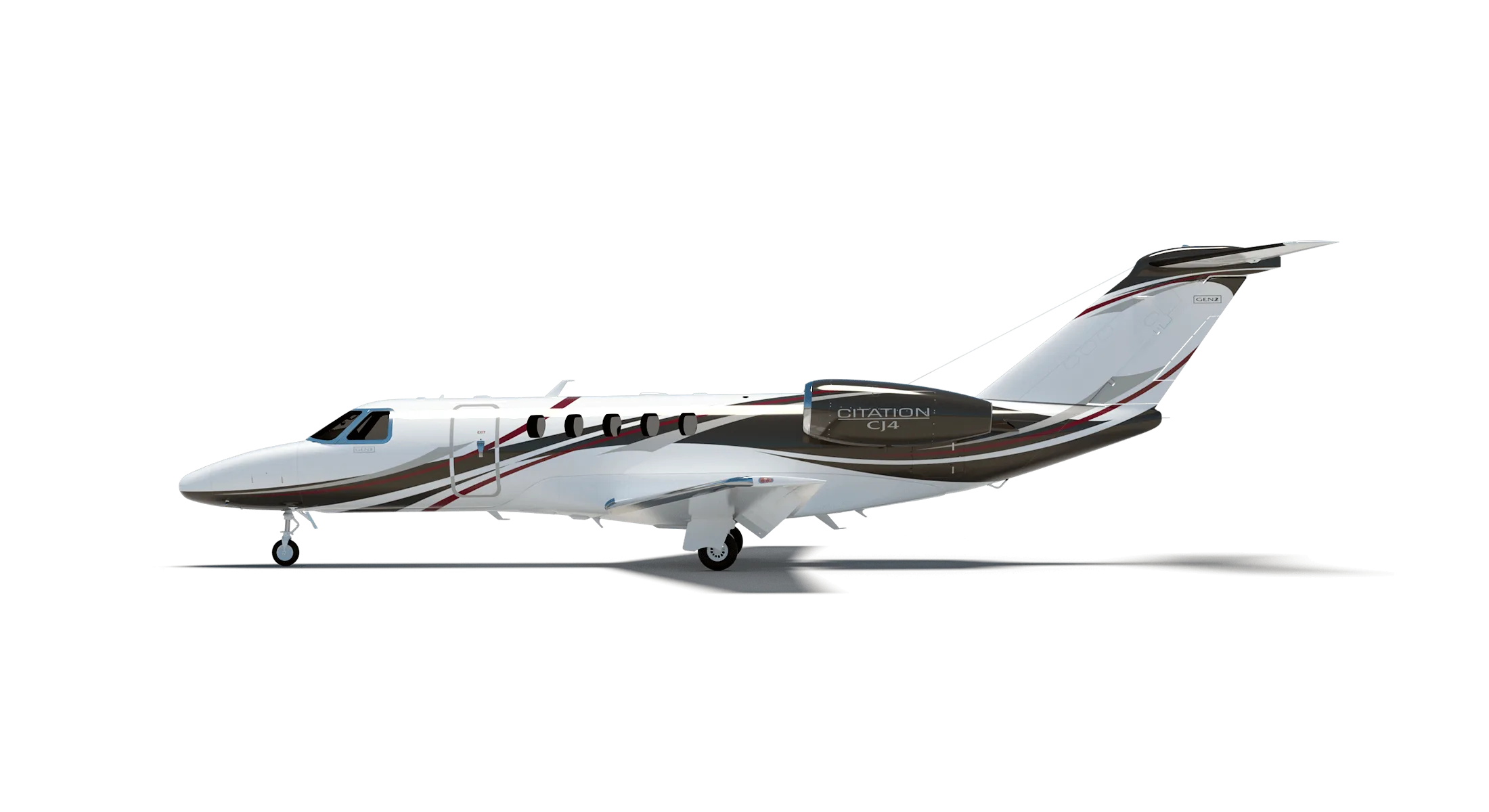
Cessna Citation CJ4 Gen2 · Other Documents
Overview
The document is an Airport Master Plan for Salinas Municipal Airport, focusing on the facility requirements to accommodate future aeronautical and non-aeronautical demand. It outlines the critical aircraft, including the Cessna Citation CJ4, and discusses the necessary infrastructure and facilities needed to meet FAA-approved forecasts. The planning period extends from 2022 to 2042, and the document is structured to guide development in short-term, mid-term, and long-term phases. Key components include airspace, airfield, landside, general aviation, and support facilities, ensuring that the airport can effectively serve its projected operational needs.
- The Cessna Citation CJ4 is a critical aircraft for Salinas Airport, influencing runway design and operational procedures.
- Runway 13/31 is the primary runway equipped with an instrument landing system, while Runway 8/26 serves as a secondary runway.
- The planning period for the Airport Master Plan extends from 2022 to 2042, focusing on short-term, mid-term, and long-term needs.
- Navigational aids at the airport include a glideslope, localizer, and various visual aids, with recommendations for upgrades.
- Instrument approach procedures are crucial for operations, particularly under low visibility conditions.
Document
Source
Originally published by www.salinas.gov. Sprinkle hosts a reference copy with an added summary, specifications and searchable full text.
Document details
- Type
- Other Documents
- Year
- 2024
- Pages
- 67
- File size
- 4.0 MB
- Publisher
- www.salinas.gov
Common. Rarer than 2% of the aircraft models we track.
Most owners only have the POH. Here's the essential set for the Cessna Citation CJ4 Gen2.
- Pilot's Operating Handbook / AFM
- Checklist
- Maintenance Manual
- Parts Catalog (IPC)
- Systems & Wiring
- Service Bulletins
- Type Certificate (TCDS)
Cessna Citation CJ4 Gen2 for sale now


Free — save the Citation CJ4 to your watchlist and track it in one place.
More Cessna Citation CJ4 Gen2manuals & documents
- 2025 CESSNA CITATION CJ4 GEN 2Systems Description
- CITATION CJ4 GEN2Performance Data
- CITATION CJ4 GEN 2Performance Data
- 2021 FACT BOOKWiring Diagram
- CITATION CJ4 GEN2Specifications
- CESCOM 10 - Aircraft Status ReportService Bulletins
- Inflight GuideEmergency Procedures
- C I T A T I O N C J 4Performance Data
- 2015 Cessna Citation CJ4 S/N 525C-0193Systems Description
- 2011 Cessna CJ4 Specification and SummarySpecifications
- MASTER MINIMUM EQUIPMENT LIST CESSNA CITATION CE-525C CJ4Checklist
- Working Title Citation CJ4 Quick Reference ChecklistPilot's Operating Handbook
If you fly the Cessna Citation CJ4 Gen2, you may also be researching these.

In this document
Introduction
The Requirements Chapter of the Airport Master Plan outlines Salinas Airport's ability to meet future demand through a detailed analysis of existing conditions and forecasts. It identifies necessary infrastructure and facilities to support aeronautical and non-aeronautical activities over a 20-year planning period, segmented into short-term, mid-term, and long-term needs.
Critical Aircraft
The critical aircraft for Salinas Airport includes the Cessna Citation CJ4, which influences runway and taxiway design. The document specifies that both Runway 8/26 and Runway 13/31 are designed to accommodate this aircraft, with Runway 13/31 being the primary runway due to its instrument landing system.
Runway Design Code (RDC)
The Runway Design Code for Salinas Airport is determined by the critical aircraft, including the Cessna Citation CJ4. The document outlines visibility minimums and design standards for each runway, ensuring compliance with FAA regulations.
Airspace and NAVAID Requirements
This section discusses the navigational aids available at Salinas Airport, including electronic and visual aids necessary for safe operations. It highlights the need for upgrades and replacements to enhance operational efficiency and safety.
Instrument Approaches
The document details the instrument approach procedures available for each runway, including RNAV (GPS) approaches for Runway 13/31 and the limitations of Runway 26 due to terrain. It emphasizes the importance of maintaining low visibility minimums to maximize operational utility.
Full document text
Chapter 5 – DRAFT Demand / Capacity and Facility Requirements Airport Master Plan | Salinas Municipal Airport Draft Prepared by: C&S Companies | Salinas Municipal Airport | Master Plan I 1 Inventory 2 Environmental Baseline 3 Regional Context 4 Forecast 5 Facility Requirements [This page has intentionally been left blank] C&S Companies | Salinas Municipal Airport | Master Plan II Table of Contents 5.1 Introduction ................................................................................................... 1 5.1.1 Forecast Summary ........................................................................................................................................ 1 5.1.2 Critical Aircraft ............................................................................................................................................... 2 5.1.3 Runway Design Code (RDC) ..................................................................................................................... 1 5.1.4 Taxiway Design Group (TDG) ................................................................................................................... 1 5.2 Airspace and NAVAID Requirements .......................................................... 3 5.2.1 Navigational Aids (NAVAID) ..................................................................................................................... 3 5.2.2 Instrument Approaches .............................................................................................................................. 3 5.2.3 Airspace Protection ...................................................................................................................................... 7 5.3 Airfield Requirements ................................................................................... 8 5.3.1 Hourly Capacity and Annual Service Volume..................................................................................... 8 5.3.2 Runway Requirements ............................................................................................................................. 12 5.3.3 Runway Protective Surfaces ................................................................................................................... 18 5.3.4 Taxiway/Taxilane Requirements ........................................................................................................... 29 5.3.5 Taxiway Access Factors ............................................................................................................................ 35 5.3.6 Airfield Pavement....................................................................................................................................... 35 5.3.7 Airfield Lighting .......................................................................................................................................... 39 5.3.8 Signage .......................................................................................................................................................... 39 5.3.9 Airfield Markings ........................................................................................................................................ 40 5.4 Landside Facility Requirements ................................................................. 41 5.4.1 Vehicle Access ............................................................................................................................................. 41 5.4.2 Vehicle Parking ........................................................................................................................................... 41 5.4.3 Perimeter / Security Fencing and Access Gates ............................................................................. 43 5.4.4 Land Use........................................................................................................................................................ 44 5.4.5 Terminal / Airport Administration Building ..................................................................................... 45 5.5 General Aviation .......................................................................................... 46 5.5.1 Aircraft Hangars ......................................................................................................................................... 46 5.5.2 Aircraft Parking Apron ............................................................................................................................. 48 5.6 Airport Support Facilities and Equipment................................................ 51 5.6.1 ARFF & Other Emergency Services ..................................................................................................... 51 5.6.2 City Maintenance & Equipment Building ......................................................................................... 51 5.6.3 Fueling Facilities ......................................................................................................................................... 51 5.6.4 Airport Traffic Control Tower ................................................................................................................ 52 C&S Companies | Salinas Municipal Airport | Master Plan III 5.7 Utilities and Infrastructure ......................................................................... 53 5.7.1 Airfield Electrical Vault ............................................................................................................................. 53 5.8 Sustainability Workshop Input .................................................................. 54 5.8.1 Airside Facility Requirements Feedback ............................................................................................ 54 5.8.2 Landside Facility Requirements Feedback........................................................................................ 55
Show full textShow less
5.8.3 Summary ....................................................................................................................................................... 56 5.9 Requirements Summary ............................................................................. 57 5.9.1 Airspace Requirements ............................................................................................................................ 57 5.9.2 Airfield Requirements............................................................................................................................... 57 5.9.3 Landside Requirements ........................................................................................................................... 58 5.9.4 Access, Circulation, and Parking Facility Requirements .............................................................. 58 5.9.5 Airport Support Facility Requirements .............................................................................................. 58 (Click the header at any point to return to the Table of Contents) C&S Companies | Salinas Municipal Airport | Master Plan IV Figures Figure 5.1 - Taxiway Design Groups ........................................................................................................................ 2 Figure 5.2 - 100 Percent of Fleet at 60 or 90 Percent Useful Load ............................................................ 15 Figure 5.3 - Example RSA, ROFA, and RPZ ......................................................................................................... 19 Figure 5.4 - Runway 8 End RSA/ROFA Penetrations ....................................................................................... 22 Figure 5.5 - Runway 26 End RSA/ROFA Penetrations .................................................................................... 22 Figure 5.6 - Runway 13 End RSA/ROFA Penetrations .................................................................................... 23 Figure 5.7 - Runway 31 End RSA/ROFA Penetrations .................................................................................... 23 Figure 5.8 - Runway 8 End RPZ Penetrations .................................................................................................... 25 Figure 5.9 - Runway 13 End RPZ Penetrations .................................................................................................. 26 Figure 5.10 - B-II to C-II: RSA and ROFA Impacts ............................................................................................ 27 Figure 5.11 - B-II to C-II: RPZ Impacts .................................................................................................................. 28 Figure 5.12 - Problematic Taxiway Geometry.................................................................................................... 33 Figure 5.13 - Run Up Areas ...................................................................................................................................... 34 Figure 5.14 - PCI ........................................................................................................................................................... 36 Figure 5.15 - Airfield Pavement Major Work Projections ............................................................................. 38 Figure 5.16 - Enhanced Centerline (Typical) ...................................................................................................... 40 Figure 5.17 - Markings Directional and Mandatory Hold (Typical) ........................................................... 40 Figure 5.18 - Airfield Fencing .................................................................................................................................. 44 Figure 5.19 - Apron Area ........................................................................................................................................... 50 Figure 5.20 - Fuel Sales by Year .............................................................................................................................. 52 C&S Companies | Salinas Municipal Airport | Master Plan V Tables Table 5.1 - SNS Demand Forecast Summary ........................................................................................................ 1 Table 5.2 - Critical Aircraft Characteristics ............................................................................................................. 2 Table 5.3 - Visibility Minimums.................................................................................................................................. 1 Table 5.4 - SNS Runway Design Codes................................................................................................................... 1 Table 5.5 – Electronic and Visual NAVAIDs ........................................................................................................... 3 Table 5.6 - NAVAID Facility Requirements ............................................................................................................ 3 Table 5.7 - Lowest IAP Minimums ............................................................................................................................ 5 Table 5.8 - Criteria to Support Instrument Flight Procedure Development ............................................. 6 Table 5.9 – ACDM Aircraft Classification System ............................................................................................. 10 Table 5.10 – Hourly Capacity ................................................................................................................................... 11 Table 5.11 – Annual Service Volume..................................................................................................................... 12 Table 5.12 – Runway Width Requirements......................................................................................................... 12 Table 5.13 – Existing and Future Critical Aircraft Characteristics ............................................................... 14 Table 5.14 – Runway Length Requirements ....................................................................................................... 17 Table 5.15 - Runway Designation Requirements ............................................................................................. 17 Table 5.16 - Runway Strength ................................................................................................................................. 18 Table 5.17 – Runway Safety Area Dimensions .................................................................................................. 20 Table 5.18 – Runway Safety Area Requirements .............................................................................................. 20 Table 5.19 – Runway Object Free Area Dimensions........................................................................................ 21 Table 5.20 – Runway Object Free Area Requirements ................................................................................... 21 Table 5.21 - Runway Protection Zones (RPZs) .................................................................................................. 24 Table 5.22 - Runway Protection Zone Requirements ..................................................................................... 25 Table 5.23 - Taxiway Width Requirements ......................................................................................................... 30 Table 5.24 - Taxiway/Taxilane Separation Requirements ............................................................................. 30 Table 5.25 - Taxiway/Taxilane Safety Area and Object Free Area Dimensions ..................................... 31 Table 5.26 - Taxilane Protective Surface Requirements ................................................................................ 31 Table 5.27 - Non-Standard Taxiway Geometry Requirements ................................................................... 32 Table 5.28 - Taxiway Exit Ranges ........................................................................................................................... 35 Table 5.29 – Fair to Serious Pavement Sections ............................................................................................... 39 C&S Companies | Salinas Municipal Airport | Master Plan VI Table 5.30 - Public Vehicle Parking Requirements .......................................................................................... 42 Table 5.31 - General Aviation Terminal Space Requirements ..................................................................... 46 Table 5.32 - Average Aircraft Space Requirements......................................................................................... 47 Table 5.33 - Existing Hangar and Demand Summary .................................................................................... 47 Table 5.34 - Northside Hangar Useful Life Analysis ........................................................................................ 48 Table 5.35 - Apron Area Demand Summary ...................................................................................................... 50 C&S Companies | Salinas Municipal Airport | Master Plan 1 5.1 Introduction The Requirements Chapter of the Airport Master Plan is intended to determine Salinas Airport’s (SNS) ability to accommodate future aeronautical and non-aeronautical demand throughout the planning period. The requirements are developed using the Existing Conditions & Inventory Chapter, as well as the Forecast of Aviation Demand Chapter. This chapter will identify the specific types and quantities of infrastructure and facilities needed at SNS to meet the FAA’s approved forecasted aviation demand. These requirements will guide the alternative development process by examining projected perceived needs of the following major components: airspace, airfield, landside, general aviation, airport support facilities and equipment, as well as utilities and infrastructure. The 20-year planning period for the Airport Master Plan, beginning in the year 2022, extends through 2042. Development throughout the planning period is broken down into three planning periods: short-term (1-5 years), mid-term (6-10 years), and long-term (11-20 years). Short-term planning is focused on the immediate needs of the airport, mid-term planning focuses on a more detailed and in-depth evaluation of airport needs, long-term planning is focused on the ultimate needs of the Airport. It is important to note that the needs of the Airport may vary throughout the 20-year planning period. However, the City of Salinas can make an informed decision regarding forecasted demand-based development using the three planning periods. This chapter provides a review of the facility needs for the following: Airspace Airfield Capacity and Facilities Landside and General Aviation Facilities Support Facilities Utilities and Infrastructure 5.1.1 Forecast Summary A summary of the FAA-approved aviation demand forecast, based on the three planning periods, is provided in Table 5.1. Additional information on the forecast can be found in the Forecast of Aviation Demand Chapter. Table 5.1 - SNS Demand Forecast Summary 2022 Existing 5 Year 10 Year 15 Year 20 Year Based Aircraft 163 173 183 193 203 Annual Operations 62,335 82,688 83,737 84,801 85,879 Source: C&S Engineers, Inc., 2024 (Forecast of Aviation Demand) C&S Companies | Salinas Municipal Airport | Master Plan 2 5.1.2 Critical Aircraft The Airport’s critical aircraft, or design aircraft, represents the largest or most demanding aircraft anticipated to make regular use of the airport facilities for at least 500 operations annually. An airport’s critical aircraft affects key aspects of design, such as the sizing of runways and taxiways/lanes, the location of aircraft parking areas, number and size of hangar facilities, and protected airspace surfaces. As indicated in FAA AC 150/5300-13B, Airport Design and described in the Forecast of Aviation Demand Chapter, an airport’s critical aircraft determines the Aircraft Approach Category (AAC) and Aircraft Design Group (ADG). The FAA requires a critical aircraft designation for each runway at an airport. At Salinas, Runway 13/31 is 4,825 feet long and considered the primary runway as it is equipped with an instrument landing system including approach lights. Runway 8/26 is 6,004 feet long and classified as the secondary runway due to the lack of precision instrument approach. Due to the primary runway having superior approach minimums and the secondary runway being longer it is assumed that both runways will see similar numbers of operations. For this reason, both runways share the same critical aircraft. The existing and future critical aircraft are a family of aircraft and are presented in the table below. Table 5.2 - Critical Aircraft Characteristics Runway Critical Aircraft AAC ADG TDG Existing 8/26 Beech 200 Super King Air, Cessna Citation CJ4, and Cessna Citation II/Bravo B II 2A 13/31 (Primary) Beech 200 Super King Air, Cessna Citation CJ4, and Cessna Citation II/Bravo B II 2A Future 8/26 Learjet 75, Beech 200 Super King Air C II 2A 13/31 (Primary) Learjet 75, Beech 200 Super King Air C II 2A Source: Aircraft Characteristics Data, Appendix 1 of AC 150-5300-13B, effective 03/31/2022; https://cessna.txtav.com/en/turboprop/caravan; https://www.globalair.com/. Discussion justifying Runway 13/31 as the primary runway is included in the Inventory Chapter. C&S Companies | Salinas Municipal Airport | Master Plan 1 5.1.3 Runway Design Code (RDC) The RDC signifies standards to which the runway is to be built and maintained. The AAC and ADG along with approach visibility minimums are combined to form the RDC of a specific runway. The final component of the RDC relates to the Runway Visibility Range (RVR) minimums for the instrument approaches into each runway as depicted in Table 5.3. The Runway Design Code (RDC) of each runway at SNS differs due to varying visibility minimums. Table 5.4 outlines the existing and future RDC components for each runway. Table 5.3 - Visibility Minimums RVR (FT) Instrument Flight Visibility Category (statute mile) Visual Visual Approach 5,000 Not lower than 1 mile 4,000 Lower than 1 mile but not lower than ¾ mile 2,400 Lower than ¾ mile but not lower than ½ mile 1,600 Lower than ½ mile but not lower than ¼ mile 1,200 Lower than ¼ mile Source: FAA AC 150/5300-13B, Table 1-3. Visibility minimums Table 5.4 - SNS Runway Design Codes Runway End Critical Aircraft AAC ADG Visibility Minimums (RVR) (FT) Existing 8/ 26 Beech 200 Super King Air, Cessna Citation CJ4, and Cessna Citation II/Bravo B B II II 5,000 Visual 13/ 31 Beech 200 Super King Air, Cessna Citation CJ4, and Cessna Citation II/Bravo B B II II 4,000 2,400 Future 8/ 26 Learjet 75, Beech 200 Super King Air C C II II 5,000 Visual 13/ 31 Learjet 75, Beech 200 Super King Air C C II II 4,000 2,400 Source: FAA AC 150/5300-13B, C&S Engineers, Inc. 5.1.4 Taxiway Design Group (TDG) A critical aircraft is also used to determine the Taxiway Design Group (TDG) at an airport. The TDG dictates the taxiway/taxilane width and fillet standards (radius of curvature at the intersection of two taxiways or a taxiway and a runway), as well as separation requirements. A C&S Companies | Salinas Municipal Airport | Master Plan 2 TDG is determined by plotting the design aircraft’s main gear width (MGW) to its cockpit to main gear distance (CMG) on the graph shown in Figure 5.1. For both he existing and future critical aircraft, the Beech 200 is the most demanding from a TDG perspective. With a MGW of 17.17 ft and a CMG of 15 ft, as noted in the FAA Aircraft Characteristics Database, dated 2/7/2023 (https://www.faa.gov/airports/engineering/aircraft_char_database), it falls within the TDG 2A category. Figure 5.1 - Taxiway Design Groups Source: FAA AC 150/5300-13B, Figure 1-1, Taxiway Design Groups (TDGs) Notes: 1.) Values in the graph are rounded to the nearest foot. 1 foot = 0.305 meters. 2.) CMG = Cockpit to Main Gear Distance: The distance from the pilot’s eye to the main gear turn center. 3.) MGW = Main Gear Width: The distance from the outer edge to outer edge of the widest set of main gear tires. C&S Companies | Salinas Municipal Airport | Master Plan 3 5.2 Airspace and NAVAID Requirements 5.2.1 Navigational Aids (NAVAID) As discussed in Existing Conditions & Inventory, the electronic navigational aids at the Airport include a glideslope, localizer, VORTAC, and ASOS. The visual navigational aids include a four- light VASI on the Runway 13 end, a two-light PAPI on the Runway 31 end, two-light VASI’s on both ends of Runway 8/26, wind cones, and a rotating beacon. Table 5.5 – Electronic and Visual NAVAIDs Electronic NAVAIDs Visual NAVAIDs RWY 31: Glideslope and Localizer (ILS) VORTAC RNAV (GPS) RWY 13: VASI-4L, REIL RWY 13/31: HIRL RWY 31: PAPI-2L, MALSR RWY 8: VASI-2L RWY 8/26: MIRL RWY 26: VASI-2L, REIL Misc: Beacon, MITL, Segmented Circle, Lighted Wind Cones Source: C&S Engineers, Inc. FAA AC 150/5300-13B, Airport Design; AC 150/5340-30J, Design and Installation Details for Airport Visual Aids; Order 7031.2C, Airway Planning Standard Number One – Terminal Air Navigation Facilities and Air Traffic Control Services; and the Aeronautical Information Manual (AIM) offer guidance on the types of visual and electronic NAVAIDs that should be present at an airport. Based on a review of these documents, and the conditions detailed in Section 1, the Airport should address the following navigational aid needs: Table 5.6 - NAVAID Facility Requirements NAVAID Requirement VASI Replace VASIs on Runway Ends 13, 8, and 26 with PAPI equipment. VORTAC The VORTAC is aging and with the availability of ILS, RNAV, and LOC approaches it does not significantly benefit the Airport. It is recommended that the VORTAC be relocated to free up the east side of the airfield for future development. Source: C&S Engineers, Inc. 5.2.2 Instrument Approaches Instrument approach procedures to a runway end are used by landing aircraft to navigate to the airport when the cloud ceiling is less than 1,000 feet above ground level and/or visibility is less than three statute miles. Establishing approaches with the lowest possible weather minimums C&S Companies | Salinas Municipal Airport | Master Plan 4 allow the airport to maximize its operational utility. Each approach type requires differing infrastructure and navigational aids. This section discusses possible instrument procedure upgrades/options that can be explored for SNS. FAA airport design standards must be met as shown in Table 5.8. Further coordination with the FAA Flight Procedures Office is recommended to review the feasibility of implementing any new approach procedure and/or improvements to existing instrument approaches. Runway 8/26 Runway 8/26 currently offers a single RNAV (GPS) approach to the Runway 8 end. The Runway 26 end would benefit from an instrument approach because it is aligned with the prevailing winds and is longer than Runway 13/31. The possibility of creating an instrument approach for the Runway 26 has been explored by both the FAA design group, the Airport, and the FAA Flight Procedures group. It was determined that due to the mountainous terrain approximately three miles to the east of the Airport, a standard instrument approach would not be pursued. While it would likely be possible to create a non-standard approach with a steep descent, the resulting approach minimums would be high enough that they would negate the benefit of having the approach in the first place. In lieu of publishing a new approach to the Runway 26 end, aircraft can utilize the existing “Circle to Land” procedure that is available on the approaches to all the other runway ends. It should be noted that due to the safety concerns from the rising terrain to the east and west of the Airport as well as the general limitations of a circling approach, minimums for these approaches will always be higher than that of a straight in approach and will not provide the same level of service. Runway 13/31 Runway 13/31 is served by RNAV (GPS) approaches to both ends of the runway, a VOR approach to Runway 13, and an ILS and LOC approach to Runway 31. These approaches currently provide sufficient coverage to both ends of the runway. It is possible that the approach minimums for the Runway 13 RNAV procedure could be lowered to below ¾ SM visibility to further increase the capability of this runway end. However, as stated in Table 5.8 below, this would require the addition of an approach lighting system to this runway end. It is unlikely that the marginal decrease in visibility minimums on this runway end would benefit the Airport and its users enough to warrant the cost of installing the additional instrumentation required. A summary of the available instrument approach procedures and the lowest available minimums is found in Table 5.7 below. A full list of all the current Instrument Approach Procedures (IAPs) can be found in the Existing Conditions & Inventory Chapter. C&S Companies | Salinas Municipal Airport | Master Plan 5 Table 5.7 - Lowest IAP Minimums Runway End Instrument Approach Procedures Available Lowest Available Visibility Minimums Runway 8 RNAV (GPS) 684 FT, 1 SM: RNAV Runway 26 Visual Only 456 FT, 1 SM: Circling Approach from RWY 31 Runway 13 RNAV (GPS) VOR 250 FT, ¾ SM: RNAV (GPS) Runway 31 ILS LOC RNAV (GPS) 220 FT, 2400 RVR: ILS or RNAV (GPS) Source: AirNav Instrument Approach Procedures SNS (14 July 2022 – 11 August 2022) C&S Companies | Salinas Municipal Airport | Master Plan 6 Table 5.8 - Criteria to Support Instrument Flight Procedure Development Visibility Minimums1 Standards1 < 3/4 Statute Mile 3/4 to < 1 Statute Mile ≥ 1 Statute Mile, Straight-In Circling2, ≥ 1 Statue Mile HAT3 ≤ 250 FT ≥ 250 FT ≥ 250 FT ≥ 350 FT POFZ (PA and APV Only) Required Not Required Not Required Not Required IT-OFZ Required Not Required Not Required Not Required ALP4 Required Required Required Required Minimum Runway Length 4,200 FT 3,200 FT 5 3,200 FT 5 3,200 FT 5 Paved Surface Required Recommended6 Recommended6 Recommended6 Runway Markings (AC 150/5340-1) Precision Non-precision Non-precision Visual Holding Position Signs and Markings (AC 150/5340-1, AC 150/5340-18) Required Required Required Required Runway Edge Lights7 HIRL or MIRL HIRL or MIRL MIRL or LIRL MIRL or LIRL (Required only for night minimums) Parallel Taxiway8 Required Required Recommended Recommended Approach Lights9 Required Recommended10 Recommended10 Not Required VGSI11 Recommended Recommended Recommended Recommended Applicable Runway Design Standards Lower than 3/4- mile visibility minimums Not lower than 3/4-mile visibility minimums Not lower than 1- mile visibility minimums Not lower than 1-mile visibility minimums Approach or Departure Surface to be Met (AC 150/5300-13B, Paragraph 3.6.1) See Table 3-3 or Table 3-4 See Table 3-3 or Table 3-4 See Table 3-3 or Table 3-4 Table 3-3 Optimum Survey Type12 VGS VGS NVGS NVGS Source: FAA AC 150/5300-13B, Appendix K, Table K-1 Numbered Notes for Table K-1: Note 1: Visibility minimums and described standards are subject to the application of FAA Order 8260.3 (TERPS) and associated orders. For each level of visibility, meet or exceed the optimum conditions within the column. Note 2: For runways authorized for circling, meet requirements for threshold siting (reference paragraph 3.5) and OFZ (reference paragraph 3.11). Note 3: HAA for circling. The HAT/HAA indicated is for planning purposes; actual obtainable HAT/HAA is determined by TERPS and may be higher due to obstacles or other requirements. Note 4: An ALP is only required for obligated airports in the NPIAS; it is recommended for all others. C&S Companies | Salinas Municipal Airport | Master Plan 7 Note 5: Runways less than 3,200 FT are protected by 14 CFR Part 77 to a lesser extent. However, runways as short as 2,400 FT could support an instrument approach provided the lowest HAT is based on clearing any 200 FT obstacle within the final approach segment. Note 6: Unpaved runways require case-by-case evaluation by the IFP Validation Team (IVT). Note 7: Runway edge lighting is required for night approach minimums. High intensity lights and an RVR touchdown zone sensor are required for RVR-based minimums. Note 8: A full-length parallel taxiway leading to and from the thresholds is advisable to achieve the lowest possible minimums, and minimizes the time aircraft are on the runway. Refer to the minimum visibility requirements on airport conditions in FAA Order 8260.3. Construction of a parallel taxiway, while advisable, is not a requirement for publication of an IFP with visibility minima ≥ 1 statute mile. Note 9: Not applicable to Performance Based Navigation procedures. The following standards are applicable to conventional, ground-based procedures. A full approach light system (ALSF-1, ALSF-2, Simplified Short Approach Light System with Runway Alignment (SSALR), or MALSR) is required for visibility < 3/4 statute mile. Intermediate (MALSF, MALS, SSALF, SSALS, Short Approach Lighting System (SALS)/SALSF) or Basic (ODALs) systems will result in higher visibility minimums. An ALSF-1 or ALSF-2 is required for CAT II/III ILS. HAT < 250 FT without MALSR, SSALR, or ALSF is permitted with visibility not less than 3/4 statute mile. Note 10: ODALS, MALS, SSALS, and SALS are acceptable. Approach lights are recommended where a visibility minima improvement of at least 1/4 statute mile can be achieved. Note 11: To preclude a non-standard IFP, it is critical the instrument approach vertical descent angle (VDA) or glidepath angle (GPA) is coincident with the VGSI angle. Note 12: See AC 150/5300-18 for VGS and non-Vertically Guided Survey (NVGS) requirements. When an AC 150/5300-18 VGS is not available, the equivalent legacy vertically guided (VG) surveys are area navigation approach precision vertical landing (ANAPV)/ localizer performance with vertical guidance (LPV)/PC, and PIR. Note 13: Absence of a survey does not preclude authorization to establish circling to a runway but may result in the procedure being restricted to daytime only operations. 5.2.3 Airspace Protection An analysis was conducted to identify obstructions to airspace surfaces utilizing aeronautical survey data collected in May 2022 by Martinez Geospatial. Initial results have identified a number of obstructions on the approach end of Runway 8 and Runway 13. These obstructions include trees, light poles, roads and buildings. See Appendix 10-A of the full Airport Layout Plan drawing set for detailed obstruction data as well as proposed dispositions for each obstruction. Obstructions should be addressed in near-term (years 1 to 5) of the planning period as this is a top priority safety item with the FAA. C&S Companies | Salinas Municipal Airport | Master Plan 8 5.3 Airfield Requirements FAA standards are utilized in this analysis for developing airport facilities capable of meeting both existing and forecasted levels of aviation activity. FAA AC 150/5300-13B, Airport Design, uses coding systems to relate airport design criteria to the operational and physical characteristics of the aircraft that operate or are projected to operate, at an airport. These airport design criteria will further dictate the future need for expanded airfield infrastructure and operational parameters to best plan and meet the forecasted future operations. 5.3.1 Hourly Capacity and Annual Service Volume Airfield capacity, as it applies to the Airport, is a measure of terminal area airspace and airfield saturation. It is defined as the maximum rate at which aircraft can arrive and depart an airfield with an acceptable level of delay. Measures of capacity include the following: Hourly Capacity of Runway – The maximum number of aircraft operations that can take place on the runway system in one hour Annual Service Volume (ASV) – The annual capacity or a maximum level of annual aircraft operations that can be accommodated on the runway system with an acceptable level of delay Airport Hourly Capacity and Annual Service Volume are important metrics used in aviation to determine the efficiency and capacity of an airport. Although there are a variety of techniques that can be used to analyze airfield capacity, the current technique accepted by the FAA is described in FAA AC 150/5060-5 (Consolidated), Airport Capacity and Delay. The Airport Capacity and Delay Model (ACDM) uses the following inputs to derive an estimated airport capacity. Airfield layout and runway use Meteorological conditions Navigational aids Aircraft operational fleet mix Touch-and-Go operations The hourly capacity refers to the maximum number of aircraft operations that an airport can handle in a single hour, considering factors such as runway length, taxiway layout, air traffic control capabilities, and weather conditions. It is calculated by dividing the total available runway capacity (in terms of takeoff and landing movements) by the minimum required separation time between aircraft. The annual service volume refers to the total number of passengers and cargo that an airport can handle in a year. These calculations are useful in determining if the airport can handle an increasing number of flights and useful in planning infrastructure upgrades and improvements to meet future demand. C&S Companies | Salinas Municipal Airport | Master Plan 9 5.3.1.1 Airfield Layout and Runway Use The airfield layout refers to the location and orientation of runways, taxiways, and other facilities. The Airport has two intersecting runways, Runway 8/26 and Runway 13/31, with full-length parallel taxiways serving both runways. 5.3.1.2 Meteorological Conditions Wind conditions are of prime importance in determining runway use and orientation. The prevailing wind and visibility conditions determine the direction takeoffs and landings may be conducted. The terms Visual Flight Rules (VFR) and Instrument Flight Rules (IFR) are used to define the current weather conditions and operating rules for these associated conditions. VFR conditions occur when the cloud ceiling is at least 1,000 feet and visibility is three statute miles or greater. During these conditions, pilots fly on a see-and-be-seen basis. IFR conditions occur when the ceiling is less than 1,000 feet or visibility drops below three miles. In IFR conditions the air traffic control system assumes responsibility for safe separation between aircraft. An analysis of the previous 10-years of ASOS data from SNS indicated that VFR conditions are present at the Airport 85% of the time and IFR conditions 15% of the time. For comparison, information obtained from Master Plans at the Marina Airport (OAR)1 and Monterey Regional Airport (MRY)2 indicate that VFR conditions are present 72% of the time at both fields. 5.3.1.3 Aircraft Operational Fleet Mix The FAA’s ACDM also requires the total annual operations to be converted to operations by specific aircraft classification category. The capacity model identifies an airport’s aircraft fleet mix in terms of four classifications ranging from A (small, single engine with gross weights of 12,500 lbs. or less) to D (large aircraft with gross weights over 300,000 lbs.). These classifications and examples of each are identified in Table 4.8. 1 Information derived from Marina Airport Master Plan p.103 Exhibit 3A Airfield Capacity Factors https://www.cityofmarina.org/DocumentCenter/View/10126/OAR-Complete-Final-Master-Plan-June-2018 2 Information derived from Monterey Regional Airport Masterplan p.191 Exhibit 3A Airfield Capacity Factors https://montereyairport.specialdistrict.org/files/ee95f8536/Complete+Vol+I+%26+II_MRY-Volume-1-Final- 012420-r_Part1-5_MRY-Volume-2-Final-012420-r_Part+1-4.pdf C&S Companies | Salinas Municipal Airport | Master Plan 10 Table 5.9 – ACDM Aircraft Classification System Class Description Examples A Single-engine, gross weight 12,500 lbs. or less Cessna 172/182 Cirrus SR20/22 Piper Cherokee/Warrior B Twin-engine, gross weight 12,500 lbs. or less Beechcraft Baron Cessna Citation I Piper Navajo C Gross weight 12,500 lbs. to 300,000 lbs. Beech 200 Super King Air Cessna Citation CJ4 Cessna Citation II/Bravo Learjet 75 D Gross weight more than 300,000 lbs. Boeing 747/777 Airbus A330 Source: FAA AC 140/5060-5 (Consolidated), Airport Capacity and Delay According to the ACDM classification system, the existing and future critical aircraft are Class C aircraft. The operational fleet mix at SNS is made up of the following percentages: Class A = 43.4% Class B = 46.3% Class C = 8.9% Class D = 1.4% 5.3.1.4 Touch and Go Operations A touch and go operation occur when an aircraft lands and then makes an immediate takeoff with coming to a full stop. The primary purpose of touch and go operations is for the training of student pilots. Typically, touch and go operations occur in greater numbers at general aviation airports with flight schools. In order to use Figure 2-1, ACDM assumes touch and go operations are below 50% of the total operations. 5.3.1.5 Hourly Capacity The FAA’s ACDM combines information concerning runway configuration, runway usage, meteorology, operation fleet mix, and touch and go operations to produce an hourly capacity of the airfield. A weighted hourly capacity combines the input data to determine a base for each VFR and IFR operational runway use configuration at the Airport. Each hourly capacity base is assigned a proportionate weight (based on the time each is used) to determine the weighted hourly capacity of the entire airfield. C&S Companies | Salinas Municipal Airport | Master Plan 11 According to “Figure 2-1 Capacity and ASV for long range planning” of FAA AC 150/5060-5 (Consolidated), Airport Capacity and Delay, which identifies the capacity of the airport based on runway alignment, the VFR and IFR capacities for the Airport are estimated to be 98 and 59 operations per hour, respectively. Values used in the determination of this hourly capacity included runway configuration “#9” as indicated in “Figure 2-1 Capacity and ASV for long range planning”. The below estimation of 98 VFR and 59 IFR operations per hour were compared to the peak design hour operations forecast developed in the Forecast of Aviation Demand Chapter, to determine the adequacy of the airfield to meet hourly capacity demands through 2042. As seen in Table 4.9, the airfield will have sufficient hourly capacity to meet design hour demand under both VFR and IFR conditions. Table 5.10 – Hourly Capacity Year Peak Hour at ADPM1 VFR Hourly Capacity2 IFR Hourly Capacity2 VFR Capacity Ratio IFR Capacity Ratio 2022 26 98 59 26.5% 44.1% 5 Year 34 98 59 34.7% 57.6% 10 Year 35 98 59 35.7% 59.3% 15 Year 35 98 59 35.7% 59.3% 20 Year 36 98 59 36.7% 61.0% 1Presented in Forecasts of Aviation Demand 2Capacities form FAA Advisory Circular 150/5060-5 (Consolidated), Airport Capacity and Delay. C&S Engineers, Inc. analysis for Runway-use Configuration 9 and Fleet Mix Index of less than 20 for 2022-2042. Source: C&S Engineers, Inc. 5.3.1.6 Annual Service Volume Annual Service Volume (ASV) is an indicator of relative annual operating capacity at an airport that accounts for differences in various airfield conditions such as runway use, aircraft mix, and weather conditions. As the level of operations at an airport approaches its ASV, additional increases in air traffic movements result in disproportionate increases in aircraft delays. Although many airports commonly exceed their ASV, typical guidance indicates that when an airport reaches 60% of its ASV, planning efforts should begin to remediate aircraft delays and as an airport approaches 80% of its ASV, it should start the design process to prevent aircraft delays from becoming unmanageable. FAA Advisory Circular 150/5060-5, Airport Capacity and Delay, provides guidance for calculating ASV. A demand-capacity analysis using this ASV is presented in Table 4.10. C&S Companies | Salinas Municipal Airport | Master Plan 12 Table 5.11 – Annual Service Volume Year Annual Operations1 Annual Capacity2 ASV Ratio 2022 Existing 62,335 230,000 27.1% 5 Year 82,688 230,000 36.0% 10 Year 83,737 230,000 36.4% 15 Year 84,801 230,000 36.9% 20 Year 85,879 230,000 37.3% 1Presented in Forecasts of Aviation Demand 2Capacities form FAA Advisory Circular 150/5060-5 (Consolidated), Airport Capacity and Delay. C&S Engineers, Inc. analysis for Runway-use Configuration 9 and Fleet Mix Index of less than 20 for 2022-204. Source: C&S Engineers, Inc. SNS’s is anticipated to reach 37.3% of its ASV by 2042. This indicates that no action needs to be taken during the planning period for the Airport to maintain an acceptable level of relative annual operating capacity as far as the number of runways is concerned. 5.3.2 Runway Requirements This portion of the Demand/ Capacity and Facility Requirements Chapter will look at SNS’s two runways and examine whether they meet both existing and future requirements. Specifically, the runways’ general characteristics will be analyzed with respect to FAA design and safety requirements and conformance with the runway length recommendations. Runway designation and length requirements will also be reviewed. 5.3.2.1 Runway Width Runway width standards are established in FAA AC 150/5300-13B and are based on RDC criteria. Table 4.11 outlines the FAA runway width standards, and the existing runway facilities at SNS. Currently, SNS exceeds the existing and future FAA requirements for runway width on all runways. Table 5.12 – Runway Width Requirements Runway RDC FAA Requirement Width (FT) Existing Width (FT) Existing 8/26 B-II-5000 75 150 13/31 B-II-2400 100 150 Future 8/26 C-II-5000 100 150 13/31 C-II-2400 100 150 Source: FAA AC 150/5300-13B, C&S Engineers, Inc. C&S Companies | Salinas Municipal Airport | Master Plan 13 5.3.2.2 Runway Length Runway length requirements are based on a variety of factors, the most notable of which is the takeoff distance of the critical aircraft operating on the runway. The departure requirements are often the most critical for measuring runway length needed since aircraft typically require more runway length for takeoff than they do for landing. Average high temperatures and the elevation of the runway are other factors that affect runway length requirements. The mild temperatures and low elevation of SNS make these factors less consequential. The existing and future runway length requirements for both runways were determined using FAA AC 150/5325-4B, Runway Length Requirements for Airport Design. This AC outlines the process to determine recommended runway length using the following five steps: 1. Identify the critical design aircraft that will make regular use of the proposed runway for an established planning period of at least five years. 2. Identify the airplanes that will require the longest runway lengths at maximum take-off weight (MTOW). 3. Use Table 1-1, Airplane Weight Categorization for Runway Length Requirements from FAA AC 150/5325-4B and the airplanes identified in step #2 to determine the method that will be used for establishing the recommended runway length. Except for regional jets, when the MTOW of listed airplanes is 60,000 lbs. or less, the recommended runway length is determined according to a family grouping of airplanes having similar performance characteristics and operating weights. When the MTOW of listed airplanes is over 60,000 lbs., the recommended runway length is determined according to individual airplanes. 4. Select the recommended runway length from among the various runway lengths generated by step #3 per the process identified in chapters 2, 3, or 4, as applicable. 5. Apply any necessary adjustment to the obtained runway length, when instructed by the applicable chapter of this AC, to the runway length generated by step #4 to obtain a final recommended runway length. Step 1: Identify the Critical Aircraft The selection of appropriate FAA airport design criteria is based primarily upon the critical aircraft that will be utilizing the Airport. As noted previously, the existing critical aircraft family for both runways consist of the Beech 200 Super King Air, Cessna Citation CJ4, and Cessna Citation II/Bravo (RDC B-II) and future critical aircraft is the Learjet 75 (RDC C-II). The runway length requirement associated with the future critical aircraft will need to be justified with at least 500 annual operations of that or similar aircraft but is noted here for planning purposes. C&S Companies | Salinas Municipal Airport | Master Plan 14 Step 2: Identify the aircraft that require the longest runway lengths at MTOW In this step, Maximum Takeoff Weight (MTOW) is used to define the airplane group for the runway length analysis by identifying the airplanes that will require the longest runway lengths at MTOW. Relevant design characteristics of the critical aircraft are included in Table 4.12. Table 5.13 – Existing and Future Critical Aircraft Characteristics Aircraft Engine Type MTOW (lbs.) Approach Speed (knots) Wingspan AAC + ADG TDG Number of Passengers (max) Beech 200 Super King Air Turboprop 12,500 98 54.50 FT B-II 2A 8 Cessna Citation CJ4 Jet 17,110 111 50.83 FT B-II 1B 10 Cessna Citation II/Bravo Jet 14,800 112 52.17 FT B-II 1A 10 Learjet 75 Jet 21,500 125 50.92 FT C-II 1B 10 Source: Aircraft Characteristics, Appendix 1 of AC 150/5300-13B, last revision date [2/7/2023] Step 3 – Determine the method that will be used for establishing recommended runway length FAA AC 150/5325-4B, Table 1-1 Airplane Weight Categorization for Runway Length Requirements, indicates that when determining runway length requirements, the design approach differs depending on the characteristics of the critical aircraft. The existing and future critical aircraft fall within the “Over 12,500 pounds but less than 60,000 pounds” category, so the runway length design approach used for SNS will be the “Family grouping of large airplanes” indicated in Chapter 3 of FAA AC 150/4325-4B. Step 4 – Select the recommended runway length The design method indicated above includes the application of the following information specific to SNS: • Airport elevation: 84.3 FT above mean sea level (MSL).3 • Mean Daily Maximum Temperature (MDMT) of the Hottest Month of the Year: 74.4 F (September).4 • Percentage of fleet category applicable: Figure 3-2, 100 Percent of Fleet (detailed below). 3 FAA. Airport Data and Information Portal (ADIP). Accessible at: https://adip.faa.gov/agis/public/#/airportData/SNS (Accessed 3/14/2023). 4 NOAA NCEI U.S. Climate Normals Quick Access (Accessed 3/14/2023) C&S Companies | Salinas Municipal Airport | Master Plan 15 Percentage of Fleet Since one of the existing critical aircraft at SNS (Citation II/Bravo) is specifically referenced in the Advisory Circular, (Table 3-2 in AC 150/5325-4B), Figure 3-2 was used to determine the base runway length. While the future critical aircraft is not listed on Table 3-2, it is assumed that the future critical aircraft will have the same runway length requirement as the existing family of aircraft. Application of SNS-specific information Application of the above information to the Figure 3-2, 100 Percent of Fleet curve at 60% useful load indicates that the runway length required is 4,900 ft and is 7,100 ft at 90% useful load (see Figure 5.2 below). Figure 5.2 - 100 Percent of Fleet at 60 or 90 Percent Useful Load Source: FAA AC 150/5325-4B, Runway Length Requirements for Airport Design, C&S Engineers, Inc. Anecdotal information provided by the Airport and the FBO indicate that aircraft have been diverted to nearby airports because they were not able to take off from SNS to travel to C&S Companies | Salinas Municipal Airport | Master Plan 16 locations like Chicago or other points east because of the runway lengths available at the Airport. For this reason, runway lengths for aircraft at both 60% and 90% of their useful load will be considered. Step 5 – Apply any necessary adjustments Effective Runway Gradient (takeoff only): The runway lengths obtained from the figure above are increased at the rate of 10 feet for each foot of elevation difference between the high and low points of the runway centerline. For SNS, the effective runway gradient adjustment on Runway 13/31 is 5.27 ft x 10 = 52.7 ft or rounded to 53 ft and is 14.2 ft x 10 = 142 ft for Runway 8/26. This adjustment added to the base length would provide the required takeoff runway length requirement. Wet and Slippery Runways (applicable only to landing operations of turbojet-powered airplanes): By regulation, the runway length for turbojet-powered aircraft obtained from the 60% useful load curves are increased by 15% or up to 5,500 ft, whichever is less. The runway length adjustment for the 90% load consideration is also increased by 15% or up to 7,000 ft, whichever is less. This adjustment added to the base length would provide the required landing runway length. Runway Length: Summary The existing and future runway length analysis for Runways 13/31 and 8/26 was analyzed using the design method for aircraft in the “Over 12,500 pounds but less than 60,000 pounds” category indicated in Chapter 3 of FAA AC 150/5325-4B. Currently, the longest runway available at SNS is Runway 8/26 measuring 6,004 ft with a 396 ft displacement on the Runway 8 end due to the proximity of public roadways. To accommodate the existing and future critical family of aircraft at 90% useful load, Runway 13/31 should be extended to approximately 7,155 ft and Runway 8/26 should be 7,245 ft (see Table 4.13 below). These calculations assume that runway gradient remains the same as existing with an extension. If the runway gradient is expected to change with an extension, the required runway length may vary. C&S Companies | Salinas Municipal Airport | Master Plan 17 Table 5.14 – Runway Length Requirements Existing Length (FT) Length Required (FT) Effective Runway Gradient Adjustment (FT) Wet & Slippery Runway Adjustment (FT) Recommended Length (FT) (+Surplus/ -Deficiency) Existing/ Future Runway 13/31 4,825 4,900 (60%) 7,100 (90%) 53 735 1,065 5,500 (-675) 7,153 (-2,328) Runway 8/26 6,004 4,900 (60%) 7,100 (90%) 142 735 1,065 5,500 (+504) 7,242 (-1,238) Source: FAA AC 150/5325-4B, C&S Engineers, Inc. 5.3.2.3 Runway Designations At an airport, each runway is named and referred to by a specific number. At SNS the runways are 13/31 and 8/26, a plane might land on the 8 end of a runway and take off on the 26 end of the same runway. A runway designation is represented by two numbers that indicate the direction in which the runway is aligned with the Earth’s magnetic field or magnetic azimuth, oriented by the runway centerline. The numbers used for runway designations are based on the degrees of a compass. Runways are numbered from 01 to 036, representing each 10 degree segment of a full circle. If the magnetic azimuth ends in the number 5 then the runway designator marking may be rounded either up or down. Magnetic azimuth is determined by adjusting the geodetic azimuth associated with a runway to compensate for magnetic declination. Magnetic declination is defined as the difference between true north and magnetic north. The value of magnetic declination varies over time and global location. Magnetic declination is a natural process and periodically requires the re-designation of runways. Table 4.14 shows the runway’s true and magnetic bearing, along with the current magnetic declination. Table 5.15 - Runway Designation Requirements Runway End True Bearing Magnetic Declination Annual Change 2023 Magnetic Bearing 2023 Runway Designation Required 2042 Magnetic Bearing 2042 Runway Designation Required 8 96.82° 12.75°E 0.083°W 84.07 8 85.65 8 26 276.82° 12.75°E 0.083°W 264.07° 26 265.65 26 13 147.82° 12.75°E 0.083°W 135.07° 13 or 14 136.65 14 31 327.82° 12.75°E 0.083°W 315.07° 31 or 32 316.65 32 Source: FAA AC 150/5300-13B, C&S Engineers, Inc. C&S Companies | Salinas Municipal Airport | Master Plan 18 The magnetic bearing of Runway 13/31 is such that the runway can remain as 13/31 or be renamed as 14/32. The current rate of change is 0° 5’ W (0.083°w) per year according to the NOAA National Centers for Environmental Information (NECI). Based on this rate of change, Runway 13/31 will be required to be re-designated to Runway 14/32 around 2035. It is recommended that the runway designation is changed closer to this time and occurring with a pavement rehabilitation or reconstruction project. It is not expected that the Runway 8/26 designation will be required to change through the extents of the planning period, but it is important to note that magnetic declination can vary over time due to fluctuations in the Earth’s magnetic fields. It is critical that the declination be reviewed on a semi-annual basis and before any runway work requiring marking modifications. 5.3.2.4 Runway Strength Runway pavement strength data is available for SNS on the FAA ADIP portal. The existing strength of the runways is provided in Table 4.15. As indicated, both runways can accommodate activity by the existing and future family of critical aircraft. Table 5.16 - Runway Strength Runway Single Wheel (lbs) Double Wheel (lbs) Double Tandem (lbs) Dual Double Tandem (lbs) 8/26 80,000 136,000 244,000 N/A 13/31 120,000 235,000 401,000 935,000 Source: SNS Airport Pavement Management System Update (APMS), 2023 5.3.3 Runway Protective Surfaces Runway protective surfaces such as the Runway Safety Area, Runway Object Free Area, and Runway Protection Zone aim to protect aircraft, people, and property in the case of an aircraft deviating from its intended course while conducting conventional runway operations. The following sections outline the existing and future criteria for the runway protective surfaces at SNS. The state of future protective surfaces will be dependent on the final runway geometry; therefore, this section focuses on any deficiencies in the existing surfaces and may highlight potential deficiencies for the future. C&S Companies | Salinas Municipal Airport | Master Plan 19 Figure 5.3 shows the safety areas as discussed in this section. Figure 5.3 - Example RSA, ROFA, and RPZ Source: C&S Engineers, Inc. 5.3.3.1 Runway Safety Area (RSA) An RSA is a graded surface centered on a runway that is required to be free of all objects except for those that are ‘fixed by function’ such as runway lights and certain NAVAIDS. The purpose of the RSA is to protect aircraft in the event of an under-shoot or overrun from a runway during landing or takeoff operations. The area must be able to support emergency vehicle operations and maintenance vehicles and is required to be graded to slope away from the runway at 1.5 to 5.0 percent. The width and length of an RSA depend upon an airport’s RDC and approach C&S Companies | Salinas Municipal Airport | Master Plan 20 visibility minimums. Meeting RSA requirements is one of the FAA’s highest priorities in maintaining safety at the nation’s airports. Table 5.17 lists the Airport’s existing and future RSA requirements if approach minimums are not changed. Table 5.17 – Runway Safety Area Dimensions Runway RDC RSA Width (FT) Length Beyond/Prior Runway End (FT) Existing 8/26 B-II-5000 150 300/300 13/31 B-II-2400 300 600/600 Future 8/26 C-II-5000 500 1,000/600 13/31 C-II-2400 500 1,000/600 Source: FAA AC 150/5300-13B, C&S Engineers, Inc. Analysis of the RSA revealed several non-standard conditions. These non-standard conditions are detailed in Table 4.17. Table 5.18 – Runway Safety Area Requirements Runway End Non-Standard Condition Runway 8 End A vehicle service road crosses through the corner of the RSA Runway 26 End N/A Runway 13 End The airport perimeter fence and vehicle service road traverse the RSA. Additionally, a portion of the RSA is within a public golf course. Runway 31 End The airport perimeter fence and vehicle service road traverse the RSA. Additionally, a portion of the RSA grade exceeds the 5% limit. Source: C&S Engineers, Inc. 5.3.3.2 Runway Object Free Area (ROFA) Similar to the RSA, the ROFA must be free of objects except those required to support air navigation and ground maneuvering operations. The function of the ROFA, also centered on the runway, is to enhance the safety of aircraft operating on the runway. It is not permissible to park an airplane within the ROFA. The width and length of the ROFA depend upon an airport’s specific RDC and approach visibility minima. The ROFA does not have specific slope requirements, but the terrain within the ROFA must be relatively smooth and graded to be at or below the edge of the RSA. Table 4.18 notes the existing and future ROFA dimensions for SNS: C&S Companies | Salinas Municipal Airport | Master Plan 21 Table 5.19 – Runway Object Free Area Dimensions Runway RDC ROFA Width (FT) Length Beyond/Prior Runway End (FT) Existing 8/26 B-II-5000 500 300/300 13/31 B-II-2400 800 600/600 Future 8/26 C-II-5000 800 1,000/600 13/31 C-II-2400 800 1,000/600 Source: FAA AC 150/5300-13B, C&S Engineers, Inc. Analysis of the ROFA revealed several non-standard conditions. These non-standard conditions are detailed in Table 4.19. Table 5.20 – Runway Object Free Area Requirements Runway End Non-Standard Condition Runway 8 End The airport perimeter fence and vehicle service road are within the ROFA (Figure 5.4) Runway 26 End A vehicle service road is located within the ROFA (Figure 5.5) Runway 13 End The airport perimeter fence, vehicle service road, and public golf course are located within the ROFA (Figure 5.6) Runway 13 East Side A vehicle service road within the ROFA runs parallel to the runway for approximately half of its length. The golf course extends into the ROFA for approximately 1/3 of the length of the runway. (Figure 5.6) Runway 31 End The airport perimeter fence and vehicle service road are within the ROFA (Figure 5.7) Source: C&S Engineers, Inc. Figures 5.4-5.7 give a detailed representation of the Runway Safety Areas (RSA) and Runway Object Free Areas (ROFA) penetration zones for Runway ends at SNS. C&S Companies | Salinas Municipal Airport | Master Plan 22 Figure 5.4 - Runway 8 End RSA/ROFA Penetrations Source: C&S Engineers, Inc. Figure 5.5 - Runway 26 End RSA/ROFA Penetrations Source: C&S Engineers, Inc. C&S Companies | Salinas Municipal Airport | Master Plan 23 Figure 5.6 - Runway 13 End RSA/ROFA Penetrations Source: C&S Engineers, Inc. Figure 5.7 - Runway 31 End RSA/ROFA Penetrations Source: C&S Engineers, Inc. C&S Companies | Salinas Municipal Airport | Master Plan 24 5.3.3.3 Runway Protection Zones (RPZs) A RPZ is an area centered symmetrically on an extended runway centerline. The RPZ has a trapezoidal shape and extends prior to each runway end. The RPZ is aimed at enhancing the safety of people and property on the ground by limiting and/or restricting the construction of certain structures within its bounds. This area should be free of land uses that create glare, smoke, or other hazards to air navigation. Additionally, the FAA requires that no vertical structures are constructed within the extents of the RPZ. The dimensions of an RPZ depend on each runway’s RDC. Table 4.20 illustrates the existing and future RPZ requirements. Table 5.21 - Runway Protection Zones (RPZs) RDC Length (FT) Inner Width (FT) Outer Width (FT) Existing Approach RPZ 8/ 26 B-II-5000/ B-II-VIS 1,000/ 1,000 500/ 500 700/ 700 13/ 31 B-II-4000/ B-II-2400 1,700/ 2,500 1,000/ 1,000 1,510/ 1,750 Departure RPZ 8/ 26 B-II-5000/ B-II-VIS 1,000/ 1,000 500/ 500 700/ 700 13/ 31 B-II-4000/ B-II-2400 1,000/ 1,000 500/ 500 700/ 700 Future Approach RPZ 8/ 26 C-II-5000/ C-II-VIS 1,700/ 1,700 500/ 500 1,010/ 1,010 13/ 31 C-II-4000/ C-II-2400 1,700/ 2,500 500/ 1,000 1,010/ 1,750 Departure RPZ 8/ 26 C-II-5000/ C-II-VIS 1,700/ 1,700 500/ 500 1,010/ 1,010 13/ 31 C-II-4000/ C-II-2400 1,700/ 1,700 500/ 500 1,010/ 1,010 Source: FAA AC 150/5300-13B, C&S Engineers, Inc. Analysis of the RPZ revealed several non-standard conditions. C&S Companies | Salinas Municipal Airport | Master Plan 25 Table 5.22 - Runway Protection Zone Requirements Runway End Non-Standard Condition Runway 8 End Residential buildings and public roads within the RPZ Runway 13 End Residential/commercial buildings, public roads, and a golf course within the RPZ Source: C&S Engineers, Inc. Figure 5.8 - Runway 8 End RPZ Penetrations Source: C&S Engineers, Inc. C&S Companies | Salinas Municipal Airport | Master Plan 26 Figure 5.9 - Runway 13 End RPZ Penetrations Source: C&S Engineers, Inc. 5.3.3.4 B-II to C-II Impacts on RSAs, ROFAs, and RPZs As discussed in previous sections, the future critical aircraft classification as C-II will affect a change in dimension of the RSAs, ROFAs, and RPZs. The impact of these changes is likely significant enough that it will require changes to the runway thresholds to mitigate the number of incompatible objects. The following figures depict the increase in these surfaces if there are no changes to runway threshold. As seen below there is a significant increase in the number of incompatible objects within the protected areas. C&S Companies | Salinas Municipal Airport | Master Plan 27 Figure 5.10 - B-II to C-II: RSA and ROFA Impacts Source: C&S Engineers, Inc. C&S Companies | Salinas Municipal Airport | Master Plan 28 Figure 5.11 - B-II to C-II: RPZ Impacts Source: C&S Engineers, Inc. C&S Companies | Salinas Municipal Airport | Master Plan 29 5.3.3.5 Runway Visibility Zone The runway visibility zone (RVZ) ensures nothing blocks a pilot’s view on an intersecting runway. A clear RVZ has no objects except those fixed by function. The Airport’s RVZ is clear but would need to be re-evaluated as alternative runway lengths are considered. 5.3.3.6 Tower Line of Sight The FAA requires that a clear line of sight be maintained from the Air Traffic Control Tower (ATCT) to all movement areas on the airfield. The purpose of this requirement is to ensure that air traffic controllers can maintain visual contact with all aircraft, vehicles, and persons on the airfield that are within their control. The existing tower at SNS has a blind spot-on Taxiway B due to the row of T-hangars to the south of the taxiway. This has been an existing condition for over 20 years and has not impacted the controller’s ability to safely accommodate operations in this area. However, any future construction will be planned to completely avoid impacts to the ATCT line of sight. 5.3.4 Taxiway/Taxilane Requirements Taxiway systems should provide safe and efficient routes for aircraft ground movement to and from an airports runways and apron areas. The type and location of taxiways in relation to a runway system have a significant impact on airfield capacity. As traffic increases, the taxiway system can limit an airport’s overall capacity, especially if the configuration results in frequent runway crossings by taxiing aircraft or does not provide sufficient access to airport facilities. A taxiway is a defined path established for the taxiing of aircraft from one part of an airport to another. If an ATCT is present the taxiways are all within the movement area and under the control of the tower. A taxilane is used by aircraft for low speed and precise taxiing. They are generally located outside of the movement area, meaning that aircraft may navigate on them without receiving clearance from the air traffic control tower. SNS has several taxilanes coming off Taxiways A, B, C and D that lead to the aircraft parking aprons and hangars. FAA guidance found in FAA AC 150/5300-13B, recommends that a taxiway system should: Provide each runway with a full-length parallel taxiway Have as many bypasses, multiple accesses, or connector taxiways as possible to each runway end Provide taxiway run-up / holding bay areas for each runway end Have the most direct routes possible Have adequate curve and fillet radii C&S Companies | Salinas Municipal Airport | Master Plan 30 Avoid areas where ground congestion may occur 5.3.4.1 Taxiway/Taxilane Width The required taxiway width is determined by the TDG of the critical aircraft. In the case of SNS, the highest TDG of the composite critical aircraft is TDG 2A which specifies a required taxiway width of 35 FT. The existing taxiway system at SNS exceeds these standards. Because the width of the existing taxiways is not justified by the TDG of the critical aircraft, the decision to maintain the width of the taxiways will need to be made at the time of each taxiway reconstruction project. Table 4.22 analyzes taxiway widths at SNS. Table 5.23 - Taxiway Width Requirements Existing Taxiway Width (FT) FAA Requirement Width (FT) Width 50+ 35 Source: FAA AC 150/5300-13B, C&S Engineers, Inc. 5.3.4.2 Taxiway/Taxilane Separation Requirements As illustrated in Table 4.23 below, each parallel runway meets or exceeds the existing separation requirements for each runway – 300 ft for Runway 13/31 and 240 ft for Runway 8/26. The separation between Taxiway C and Runway 8/26 exceeds the 300 ft future requirements, but most of Taxiway B (from Runway 13/31 to the Runway 8 end) is only 240 ft from Runway 8/26, 60 ft short of the 300 ft requirement. Taxiway A is currently 385 ft from Runway 13/31 which is short 15 ft from the 400 ft separation required for the future. Table 5.24 - Taxiway/Taxilane Separation Requirements Existing Separation Existing Requirement (B-II) Future Requirement (C-II) Runway 13/31 to Taxiway A 385 FT 300 FT 400 FT (Existing is 15 FT short of standard) Runway 8/26 to Taxiway B 240 FT West of RWY 13/31 300 FT East of RWY 13/31 240 FT 300 FT (Existing west of RWY 13/31 is 60 FT short of standard) Runway 8/26 to Taxiway C 385 FT 240 FT 300 FT Source: FAA AC 150/5300-13B, C&S Engineers, Inc. 5.3.4.3 Taxiway/Taxilane Protective Surfaces To ensure safety for aircraft during taxi operations the FAA has designated protected areas that surround each taxiway and taxilane. These areas are known as the Taxiway/Taxilane Safety Area (TSA) and Taxiway/Taxilane Object Free Area (TOFA/TLOFA). They are centered on the C&S Companies | Salinas Municipal Airport | Master Plan 31 taxiway/taxilane centerline and are a set width that is determined by the ADG of the critical aircraft. Table 4.24 below lists the required widths of the taxiway protective surfaces per FAA guidelines. Table 5.25 - Taxiway/Taxilane Safety Area and Object Free Area Dimensions Surface Width In Compliance with Standards? Taxilane Safety Area 79 FT No Taxiway Safety Area 79 FT Yes Taxilane Object Free Area (TLOFA) 110 FT No Taxiway Object Free Area (TOFA) 124 FT Yes Source: FAA AC 150/5300-13B Several taxilanes at SNS do not meet the FAA established TLOFA requirements. General aviation airports often do not meet the full FAA design standards in regard to taxilane safety areas as they are frequently designed with hangar rows and taxilanes that are specifically intended for use by an aircraft significantly smaller than the design aircraft. Additionally, the FAA will often allow non-compliant taxilanes to remain but will require full compliance on any newly constructed taxilanes that accept FAA funding. While it may not be necessary to correct all the TSA and TOFA issues, the feasibility of this action and the impact it would have on Airport circulation and capacity are discussed in the Alternatives Development Chapter. Table 4.25 details the non-standard condition of taxilane protected surfaces at SNS. Table 5.26 - Taxilane Protective Surface Requirements Protective Surface Non-Standard Condition Taxilane Safety Area and Taxilane Object Free Area Existing taxilanes between hangar rows do not meet current taxilane safety area and taxilane object free area requirements Source: C&S Engineers, Inc. 5.3.4.4 Non-Standard Taxiway Geometry With the most recent release of FAA 150/5300-13B, the taxiway fillet designed standards were updated and reduced to a single standard that ensures a better margin of safety from the aircraft wheels to the edge of taxiway pavement. The airfield at SNS was constructed prior to this recent update and considering this new standard there are deficiencies noted at all runway/taxiway and taxiway/taxiway intersections. As a result, all airfield fillets should be upgraded to comply with current FAA design standards regarding taxiway fillets. These upgrades are recommended to be made at the time of the next full reconstruction of each taxiway. A stand-alone project to modify taxiway filet geometry is not economically feasible and not required by the FAA. Table 4.26 details all non-standard taxiway geometry. C&S Companies | Salinas Municipal Airport | Master Plan 32 In addition to taxiway intersection geometry, the FAA gives general guidelines to drive design of taxiway systems at airports. There are several locations on the airfield where these guidelines could be implemented to improve the taxiway system (see Figure 5.12): Table 5.27 - Non-Standard Taxiway Geometry Requirements Non-Standard Conditions Direct access to the Runway 13 end from the apron (Taxiway A) should be eliminated Holding bay pavement at the Runway 13 end should be minimized Realign taxiways intersecting a runway end at other than a right angle (Runway ends 8, 26, and 31) Realign high-energy and low-angle intersections at the Taxiway C/Runway 13/31 and Taxiway A/Runway 8/26 intersections Realign complex taxiway intersection with Taxiways C, D, and G Realign low-angle intersection of Taxiway D and Runway 8/26 Eliminate direct access to Runway 8/26 from the apron via Taxiway D Realign complex intersection with Runway 8/26 and Taxiways N, J, and L Source: C&S Engineers, Inc. C&S Companies | Salinas Municipal Airport | Master Pla 33 Figure 5.12 - Problematic Taxiway Geometry Source: C&S Engineers, Inc., FAA Airport Diagram C&S Companies | Salinas Municipal Airport | Master Plan 34 5.3.4.5 Full Length Parallel Taxiway Currently, Runway 13/31 has a full-length parallel taxiway (Taxiway A) on the west side of the runway while Runway 8/26 has a full parallel taxiway on each side (Taxiway B to the south and Taxiway C to the north). If future aeronautical development is proposed on the east side of Runway 13/31 then it is recommended to construct a parallel taxiway on this side of the runway. 5.3.4.6 Aircraft Run Up Areas At SNS, there are currently six locations that can serve as run up areas. These are used by pilots to preform pre-takeoff procedures including instrument and engine performance checks as well as to hold while waiting for clearance from ATC. Ideally the aircraft run up areas should be designed to provide a clearly marked area for pilots to park that will keep their aircraft clear of the active taxiway. The run-up areas are depicted in Figure 5.13 below. Figure 5.13 - Run Up Areas Source: C&S Engineers, Inc., FAA Airport Diagram Ideally, run-up areas are located at the runway ends directly off the taxiway and clear of any protected runway or taxiway areas. General design of holding bays include assured wingtip clearance of established critical aircraft and proper markings to guide pilots safely. Markings C&S Companies | Salinas Municipal Airport | Master Plan 35 should be labeled to have a specified area where aircraft can turn within the holding bays to not line up nose to tail with other aircraft. This will allow for aircraft to quickly enter and exit the holding bay without interfering with other aircraft in the same holding bay. 5.3.5 Taxiway Access Factors Taxiway entrance and exit locations are an important factor in determining the capacity of an airport’s runway system. Runway capacities are highest when there are full-length parallel taxiways, ample runway entrance and exit taxiways, and no active runway crossings available. All of these components reduce the amount of time an aircraft remains on the runway. FAA AC 150/5060-5, Airport Capacity and Delay, identifies the criteria for determining taxiway exit factors at an airport. The criteria for exit factors are generally based on the mix index and the distance the taxiway exits are from the runway threshold and other taxiway connections. Taxiway exits were evaluated for operations in both directions on the two runways. Table 5.28 depicts these findings. All runways have accessible taxiway exits between 2,000 feet and 4,000 feet of the landing threshold. Table 5.28 - Taxiway Exit Ranges Runway Number of Exits within Optimal Range (2,000 FT to 4,000 FT) 8 3 26 4 13 4 31 4 Source: C&S Engineers, Inc. The taxiway system located at SNS has multiple access points available for both Runway 8/26 and Runway 13/31. Runway 8/26 has two dedicated full-length parallel taxiways, one on each side of the runway. Aircraft must cross Runway 13/31 to get from both the GA hangars, located on the west side of the airport property, and the airport terminal, located on the north portion of the airport property, to reach the Runway 26 end. Runway 13/31 has one full parallel taxiway with connections to the airport terminal apron from the Runway 13 end, and the GA hangars from the Runway 31 end. 5.3.6 Airfield Pavement An airfield pavement condition analysis was conducted as part of the Pavement Management System Report completed in 2023 for SNS. The intent of the study was to present comprehensive classifications for all airfield pavement sections utilizing the industry standard Pavement Condition Index (PCI) metric. In this method, pavement sections are inspected for distress types and their severities. The inspection data is evaluated to determine the PCI of the pavement. Pavement is then classified using its PCI in categories of good, fair, or poor. The C&S Companies | Salinas Municipal Airport | Master Plan 36 pavement condition findings are depicted in Figure 5.14. It is recommended during capital improvement program development efforts that pavement condition be utilized as a factor in prioritizing future pavement rehabilitation projects. Table 5.29 lists the pavement sections that have been classified as having a “fair”, “poor”, “very poor”, or “serious” condition in the Pavement Investigation Study findings. Figure 5.14 - PCI Source: SNS Airport Pavement Management System (APMS) Update, 2023 5.3.6.1 Runway Pavement The data for the pavement condition analysis shows that Runway 13/31 has a listed outer pavement condition of “good, the middle of the pavement is “satisfactory”, but the shoulders are “poor”. Runway 8/26 is listed as “satisfactory” across the extents of the runway, but its shoulders are rated “fair”. As identified in the 2023 APMS Update, Maintenance and Reconstruction Projections, runway 13/31, outer extents do not require rehab within the next 10 years; however, the internal extents will require rehab within 7-10 years. Runway 8/26 will require rehab within 4-6 years. 5.3.6.2 Taxiway Pavement The data for the Pavement Management System Report shows that portions of the taxiway pavement are currently in need of rehabilitation. Taxiway G from the terminal apron to the intersection of Taxiway C has been rated “very poor” and Taxiway E and portions of Taxiway D have been rated “poor”. C&S Companies | Salinas Municipal Airport | Master Plan 37 As identified in the 2023 APMS Update, Maintenance and Reconstruction Projections, taxiways A, B, C, J, K, N portions of D, G, P require no rehab in the next 10 years. The helipad as well as a portion of taxiway F will require rehab in 1-3 years. Portions of taxiway F and taxiway H are currently eligible for rehab. Taxiway L will be eligible for reconstruction in 7-10 years. Taxiway P as well as a portion of taxiway A south of runway 8/26 at the A/B intersection will be due for reconstruction in 4- 6 years. Taxiway E as well as a portion of taxiway D is currently eligible for reconstruction. 5.3.6.3 Apron Pavement The data for the pavement condition analysis shows that surveyed SNS’s apron area has been classified as having a “poor”, “very poor”, or “serious” PCI rating. This includes the sections of: North apron area surrounding hangars west of Runway 13 (serious and poor) North apron area between Taxiway F and service road parallel to Taxiway A (poor) Apron area around the terminal between Taxiway G and L (very poor) Apron area between the terminal and the end of Taxiways E and F (poor) South apron area south of Runway 8 (poor) As identified in the 2023 APMS Update, Maintenance and Reconstruction Projections, there are several apron areas that are currently eligible for reconstruction, those areas include the north apron area surrounding the hangars as well as the north apron between taxiway F and A, the Terminal Apron, the south hangar apron near taxiway B, as well as a portion of taxiway G. Additionally, the south hangar apron area will be eligible for reconstruction in 1-3 years. There are several apron areas that will be eligible for reconstruction in 7-10 years including the south apron area at the midpoint of taxiway bravo and the southern portion of the terminal ramp. C&S Companies | Salinas Municipal Airport | Master Plan 38 Figure 5.15 - Airfield Pavement Major Work Projections Source: SNS Airport Pavement Management System Update, 2023 C&S Companies | Salinas Municipal Airport | Master Plan 39 Table 5.29 – Fair to Serious Pavement Sections Type of Area Section Code PCI Rating Runway 8/26 Shoulders SHDR8-26:10/20/30 Fair Runway 13/31 Shoulders SHDR13-31:10/20 Poor Taxiway D TWD:60 Poor Taxiway E TWE:10 Poor Taxiway F TWF:10 Fair Taxiway G TWG:10 Very Poor Taxiway H TWH:10 Fair Taxiway L TWL:10 Fair Taxiway P TWP:10 Fair Apron ATERM:30 Fair Apron ATERM:20 Very Poor Apron ATERM:10 Poor Apron ATD:20/30 Poor Apron ATD:10 Fair North Apron (Hangar) AHGRNO:20/30 Serious North Apron (Hangar) AHGRNO:10/60/70 Poor South Apron (Hangar) AHGRSO:20 Poor South Apron (Hangar) AHGRSO:40/50/60 Fair Source: SNS Airport Pavement Management System Update (2023) 5.3.7 Airfield Lighting The Existing Conditions & Inventory Chapter describes the existing condition of airfield lighting equipment at SNS. Currently, SNS has appropriate lighting equipment including a Medium Intensity Approach Lighting System (MALSR), Runway End Identifier Lights (REIL), and Runway and Taxiway Edge Lighting where required. Therefore, no major lighting deficiencies currently exist at SNS. Finally, any future improvements to or implementation of lighting equipment should feature energy-saving LED technologies where able and when practical. 5.3.8 Signage The Existing Conditions & Inventory Chapter describes existing conditions of airfield signage at SNS. While no specific recommendations for signage improvement are identified, airfield signage should be expanded and updated as necessary in conjunction with any airfield improvement projects. C&S Companies | Salinas Municipal Airport | Master Plan 40 5.3.9 Airfield Markings The Existing Conditions & Inventory Chapter describes existing conditions of airfield markings at SNS. While no specific recommendations for marking improvements are identified, airfield markings should be expanded and updated as necessary in conjunction with any airfield improvement projects. Figure 5.16 - Enhanced Centerline (Typical) Figure 5.17 - Markings Directional and Mandatory Hold (Typical) C&S Companies | Salinas Municipal Airport | Master Plan 41 5.4 Landside Facility Requirements The planning of landside facilities is based on the capacity of both the airside and landside areas. The requirements for terminal and support area facilities have been determined for a 20- year planning period. The principal operating elements covered under these analyses for general aviation requirements include: ♦ Vehicle Access ♦ Vehicle Parking ♦ Perimeter/Security Fencing and Access Gates ♦ Land Use ♦ Terminal/Airport Administration Building These elements are essential for the safe an efficient operation of an airport. By planning for these elements in advance, airports can ensure that they have the capacity to meet the needs of their users. 5.4.1 Vehicle Access Access to the airport is available via Airport Boulevard or Skyway Boulevard. Several tenant facilities are accessible on the south side of Moffett Street. Airport Boulevard is accessible from Veterans Memorial Highway (US-101) via Roy Diaz Street. The airport does not have wayfinding signs to guide vehicles, but the terminal building and hangars are clearly visible from primary roads. The Airport is not currently experiencing any congestion or access issues. It is not anticipated that the level of demand forecasted over the 20-year period will impact the capacity of area roadways. There are no recommended changes in vehicle access. 5.4.2 Vehicle Parking The Airport has several parking lots for tenant, employee, and visitor vehicles. The terminal parking area is the most frequently used section of SNS. Other parking areas are available near tenant facilities, including most larger hangar facilities. Many general aviation (GA) tenants park their vehicles at the tie-down or hangar where they base their aircraft. The Airport has identified that parking needs for business tenants are a concern. These needs will be analyzed further in the development of alternatives. Included in this section are calculations for public vehicle parking needs over the course of the 20-year planning period. The Existing Conditions & Inventory Chapter indicates that a total of 262 vehicle parking spaces are available at SNS contained within eight specific areas. Most of the spaces are at the terminal building and along Mortensen Avenue in front of the large hangar (161 of the 262 C&S Companies | Salinas Municipal Airport | Master Plan 42 spaces are located between these two areas). The approximate square yardage (SY) of the 161 spaces used for terminal parking is 6,261 SY. The remainder of the parking spaces are in smaller lots associated with private facilities. Since the majority of parking spaces are associated with the terminal building, the parking requirements will be in regards to that specific area. It is assumed that individual business will expand their private parking areas as necessary. The required vehicle parking needs for SNS were calculated using a combination of the design hour operations, the restaurant, rental car parking, and airport employees. This design hour and the standard 2.5 pilots and passengers per design hour operation determined the vehicle parking space requirements for pilots and passenger. It is assumed that the parking demand of restaurant patrons, rental car parking, and airport employees is 90% of the demand for pilots and passengers alone. Table 5.30 summarizes the results of these findings. Table 5.30 - Public Vehicle Parking Requirements Year Design Hour Operations Parking Spaces Requires for Pilots and Passengers Parking Spaces Required for Rental Cars, Restaurant, and Airport Employees Approx. Size (SY) 2022 Existing 26 65 59 4,803 5 Year 34 85 77 6,281 10 Year 35 88 79 6,465 15 Year 35 88 79 6,465 20 Year 36 90 81 6,650 Source: C&S Engineers, Inc Based on the existing 161 public parking spaces at the SNS terminal, no additional spaces are needed to accommodate demand with the short-term planning period. However, around the 5 to 10 year planning period it is estimated that the terminal area parking lot will require an expansion to accommodate demand. Therefore, the city should continue to monitor the public vehicle parking needs throughout the planning horizon and consider expansion as the need arises. If new facilities or tenants seek to use the parking area for a customer driven function, such as, eVTOL, Cargo Operations or other Logistical Business Sectors located at Salinas, parking may be impacted. It is recommended that the appropriate number of spots be added based on the square footage of buildings proposed at the Airport. For example, industry standard is to add 4 spaces per 1,000 square feet of building. California building code (Title 24, Part 3) may require the inclusion of Electric Vehicle (EV) charging stations for new construction and major renovations. C&S Companies | Salinas Municipal Airport | Master Plan 43 5.4.3 Perimeter / Security Fencing and Access Gates General Aviation airport security fencing is designed to prevent unauthorized access to the airport's air operations area, which includes runways, taxiways, and aprons. The security perimeter fence acts as the first line of defense against potential security breaches and unauthorized access to the airport. The Federal Aviation Administration (FAA) recommends that general aviation airports install perimeter fencing that meets the requirements outlined in FAA Advisory Circular (AC) 150/5370- 10H, Standards for Specifications for Construction of Airports. The FAA advises that the fencing be at least six feet in height and capable of preventing unauthorized access. Perimeter fencing materials can include chain-link, welded wire mesh, wood, and other materials that meet the FAA's standards for strength and durability. The perimeter fence should also be equipped with access gates that are lockable for security purposes. Access gates are an essential component of general aviation airport security perimeter fencing. Access gates provide a secure point of entry and exit for authorized personnel and vehicles, while preventing unauthorized access to the air operations area. Access gates should be equipped with locking mechanisms that prevent unauthorized entry. The FAA recommends that access gates be designed to allow easy inspection by airport maintenance and security personnel and that the gate should be monitored by security cameras or other surveillance methods. The Salinas Airport is a general aviation airport that is not subject to 14 CFR Part 139, and therefore is not required to comply with the same security regulations as commercial service airports. However, the Airport must still ensure that adequate security measures are in place to protect the Airport's facilities, aircraft, and personnel. The Salinas Airport currently has fencing and access control measures in place that provide a layer of security and safety for its users and the public. Overall, the 22,008 ft, six-foot high, galvanized chain-link perimeter fencing is in good condition. However, the Airport does lack about 2,269 ft of fencing on its northeast border with the golf course. The need for additional airport fencing will be analyzed in the Alternatives Development Chapter. An update to the Airport's Wildlife Hazard Assessment (WHA) will be able to further inform the airport of where other vulnerabilities exist in the perimeter fencing that allow wildlife to breach the perimeter and suggest measures to correct or prevent future breaches. The need for additional fencing is further illustrated by past airport security issues involving fencing or lack thereof. Figure 5.18 illustrates current airport fencing. C&S Companies | Salinas Municipal Airport | Master Plan 44 Figure 5.18 - Airfield Fencing 5.4.4 Land Use Identifying the types and distribution of land uses and zoning designations on, adjacent to, and in the close proximity of an airport is an important task for municipal airport owners. Typical land use compatibility considerations include safety, height hazards, noise exposure, and alignment with established community planning - all of which the owner should consider relative to projects, both on- and off-airport property. In the State of California, these topics are addressed in the Airport Land Use Compatibility Plan (ALUCP), which ensures that incompatible development does not occur on land surrounding an airport (non-airport property). To meet these objectives, the ALUCP addresses potential airport compatibility impacts related to four specific airport-related factors. These include: Noise – Exposure to aircraft noise. Safety – Land use that affects safety both for people on the ground and in aircraft. Airspace protection – Protection of airport airspace. Overflight – Annoyance and other general concerns related to aircraft overflights. C&S Companies | Salinas Municipal Airport | Master Plan 45 The Airport’s current ALUCP, which was formally referred to as a Comprehensive Land Use Plan (CLUP), was last amended in March 1982. Any proposed development surrounding the airport (not on airport property) would need to conform to the guidelines as outlined by the Land Use Plan. It is imperative that the Airport continue to work in conjunction with other City departments and the surrounding community on controlling the land uses and development formats surrounding the Airport via zoning and other measures, such as avigation easements and airport overlay zones, in order to meet the ALUCP requirements. 5.4.5 Terminal / Airport Administration Building The terminal building at the Airport is a multi-functional building. The terminal was intended for commercial passenger use. The building is approximately 11,398 square-feet in size. The methodology used to determine the terminal building facility requirements for general aviation airports is based on the number of airport users anticipated to use the facility during the design hour operations. The design hour is defined as the peak hour of an average day of the peak month. The design hour can be used to determine the number of passengers and pilots departing or arriving on an aircraft in an elapsed hour of a typical busy day (design day). In the case of SNS, given that the design hour operations measure the activities for the Airport as a whole, this methodology may not reflect the most accurate way to calculate the size requirements of the facility; the reasoning is the flight school and FBO customers do not routinely use the terminal building. Therefore, a modified design hour derived from the total itinerant operations during the peak month was calculated for the Airport over the course of the planning period. In order to accommodate the peak-hour traffic and to determine the building size requirements, conventional planning practices use a factor of 2.5 people (passengers and pilots) per peak-hour (design hour) and an average area of 100 square-feet of space per person for airports similar in size and activity as SNS. For SNS, applying these standards to the itinerant operations design hour produced the terminal size requirements for each planning period. Table 5.31 summarizes the GA terminal requirements for SNS using the methodologies described herein. C&S Companies | Salinas Municipal Airport | Master Plan 46 Table 5.31 - General Aviation Terminal Space Requirements Year Itinerant Design Hour Operations Peak-Hour Pilot & Passengers Terminal Size Required 2021 (Existing) 9 23 3,412 2026 12 30 4,462 2031 12 30 4,462 2036 12 31 4,594 2041 13 31 4,724 Source: C&S Engineers, Inc. According to the calculated requirements above, the existing 11,398-sq. ft. terminal building meets the space requirements. The terminal appears to have a significant excess of space , however it is occupied by other uses that are not impacted by design hour operations including the airport restaurant and leased office spaces. Although the terminal building appears to be in overall good condition, it is dated. Energy and water efficiency improvements are needed, such as mechanical, electrical, and plumbing upgrades. The Airport Administration building is located across the street from the airport terminal. This building consists of 8,502 sq. ft. of usable space. The space is further divided into 3,062 sq. ft. of office space and 3,200 sq. ft. of garage storage space. The facility has adequate parking and storage for airport personnel. 5.5 General Aviation 5.5.1 Aircraft Hangars Hangar requirements for a GA facility are determined by the number of based aircraft, the type of aircraft to be accommodated, owner preferences, and area climate. Furthermore, it is common when calculating the hangar size of a facility to use an average size requirement for the various types of aircraft, meaning that each type of aircraft will require a different amount of space (usually measured in square-feet) within a specific type of storage facility (e.g., T-hangar, single-aircraft box hangar, large multi-aircraft conventional hangar). Table 5.32 illustrates the average aircraft space requirements based on aircraft type for the Airport. C&S Companies | Salinas Municipal Airport | Master Plan 47 Table 5.32 - Average Aircraft Space Requirements Aircraft Storage Type Space Required (SF) Conventional/Box Hangar SE Piston 1,200 ME Piston 1,400 Turboprop/Jet 1,800 Rotorcraft 800 T-Hangar SE/ME (piston/turboprop) 1,400 Acronyms: Square feet (SF), single-engine (SF), multi-engine (ME). Source: C&S Engineers, Inc., 2022 The average space requirements for the various aircraft in the Airport’s based aircraft fleet mix was applied to the based aircraft forecasts to estimate hangar area requirements for each aircraft type. Of note in this analysis, there are 250 storage bays at the Airport, but the number of based aircraft will not exceed 250 during the 20-year planning period. The data analysis in this section will use the assumption that 100% of the fleet will continue to use hangar storage. The existing based aircraft data provided by airport management, along with the current aircraft storage conditions as they exist on the airfield today, were used in this analysis. Finally, using these averages and assumptions, combined with the forecasted fleet mix, Table 5.33 depicts the calculated demand requirements for hangar space at the Airport for each of the aircraft types located on the field. Table 5.33 - Existing Hangar and Demand Summary Aircraft Type 2021 (Existing) 2026 Forecast 2031 Forecast 2036 Forecast 2041 Forecast Single-Engine 159,600 169,200 177,600 187,200 196,800 Multi-Engine 19,800 19,800 22,000 22,000 22,000 Jet 6,600 6,600 8,800 11,000 13,200 Rotorcraft 17,600 19,800 19,800 22,000 24,200 Total Hangar Area (SF) 203,600 215,400 228,200 242,200 256,200 Source: C&S Engineers, Inc. The results of the hangar demand analysis illustrated in Table 5.33 above indicate that the Airport has sufficient hangar storage space for the 20-year planning period. This is inconsistent with input received from airport management, tenants, and users at the Airport. The airport manager has identified several T-Hangar structures that will see the end of their useful life during the 20-year planning period. All of the ageing infrastructure is located on the Northside of the Airport. It is expected that over the 20-year planning period approximately 50 storage units will exceed their useful life. Based on the hangar demand analysis and the existing number C&S Companies | Salinas Municipal Airport | Master Plan 48 of T-hangars present today, the Airport has excess space in the amount of 58,000 sq. ft. However, the loss of 50 individual storage units would equate to a loss approximately 65,000 sq. ft. of hangar space. Table 5.34 - Northside Hangar Useful Life Analysis Hangars Location (Northside) Square Footage Remaining Useful Life Short Term Loss Echo Row 7,800 10 Years Port-a-Ports 15,600 10 Years Medium Term Loss Delta Row 7,800 10-15 Years Long Term Loss Alpha Row 11,500 15-20 Years Bravo Row 11,500 15-20 Years Charlie Row 11,500 15-20 Years Source: C&S Engineers, Inc. According to airport management, users, and tenants there is a need for additional corporate hangars or large box hangars. The Salinas Airport is already home to an eVTOL research and developer, the storage space and amenities required of these aircraft of the future are different than what is currently in the marketplace. As the hangars in Table 5.34 come to the end of their useful life, the Airport should consider replacing them with more flexible storage options to meet the needs of a wider range of aircraft. This is consistent with industry practices. Therefore, recommendations for additional flexible corporate or box hangars will be explored in the Alternatives Development Chapter analysis and ultimately displayed on the Airport Layout Plan (ALP). It is important to note that hangars of all types are normally not eligible for FAA Airport Improvement Plan (AIP) funding and therefore are usually funded by the sponsor, private investor, or a combination thereof. Thus, it is also recommended that the City continue to monitor the actual demand for hangars at the Airport and make adjustments in the types and number of hangars as needed over the course of the planning horizon. 5.5.2 Aircraft Parking Apron There are multiple aircraft parking areas are located at the SNS with approximately 44 apron-tie- down positions and 68,100 square yards of aircraft parking apron available. In order to identify the required parking spac
2 Cessna Citation CJ4 Gen2 parts for sale
See all →
Parts listed for sale by vetted eBay sellers — confirmed on eBay at checkout.