PILOT’S OPERATING HANDBOOK AND FAA APPROVED AIRPLANE FLIGHT MANUAL for CIRRUS DESIGN SR20
Cirrus SR20 G3 · Avionics Manual
Overview
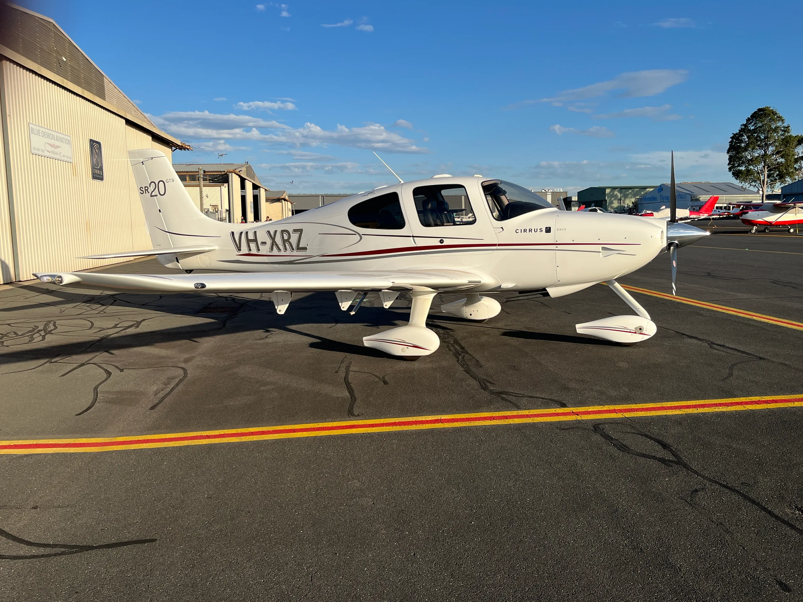
This Pilot's Operating Handbook (POH) serves as the FAA Approved Airplane Flight Manual for the Cirrus Design SR20. It is specifically tailored for airplanes registered in Brazil and operating under the Agência Nacional de Aviação Civil requirements. The handbook includes essential operational procedures, performance data, and maintenance information necessary for the safe and efficient operation of the SR20. Pilots and operators are required to comply with the limitations and instructions outlined in this manual to ensure airworthiness and adherence to FAA regulations. The document is structured to provide clear guidance on various aspects of the aircraft, including general information, limitations, emergency procedures, and performance data.
- Total fuel capacity: 60.5 U.S. gallons (229.0 L), usable fuel: 56 U.S. gallons (212.0 L).
- Maximum gross weight for takeoff: 3000 lb (1361 kg).
- Standard empty weight: 2050 lb (930 kg).
- Maximum landing weight: 2900 lb (1315 kg).
- Engine specifications: Teledyne Continental IO-360-ES, 200 hp @ 2700 rpm.
Document
Source
Originally published by encoreflight.com. Sprinkle hosts a reference copy with an added summary, specifications and searchable full text.
Document details
- Type
- Avionics Manual
- Year
- 2005
- Pages
- 478
- File size
- 6.8 MB
- Publisher
- encoreflight.com
Common. Rarer than 17% of the aircraft models we track.
Most owners only have the POH. Here's the essential set for the Cirrus SR20 G3.
- Pilot's Operating Handbook / AFM
- Checklist
- Maintenance Manual
- Parts Catalog (IPC)
- Systems & Wiring
- Service Bulletins
- Type Certificate (TCDS)
Cirrus SR20 G3 for sale now


Free — save the SR20-G3 to your watchlist and track it in one place.
More Cirrus SR20 G3manuals & documents
- PART 23 TOP PRODUCTS 2022 REV A JULY 2022Parts Catalog
- Cirrus Direct UpgradesOther Documents
- AIRCRAFT ACCIDENT FINAL REPORTOther Documents
- Summary Aircraft Data 2009 Cirrus (SR20) N511RTSystems Description
- Introducing the 2008 SR20 G3Weight And Balance
- PILOT’S OPERATING HANDBOOK AND FAA APPROVED AIRPLANE FLIGHT MANUAL for the CIRRUS DESIGN SR20Maintenance Manual
- Technical Sheet: Cirrus SR20Specifications
- Cirrus SR20 G3Specifications
If you fly the Cirrus SR20 G3, you may also be researching these.



In this document
General
This section provides an overview of the Cirrus SR20, including its engine specifications, propeller details, fuel capacity, and maximum certificated weights. It outlines the dimensions of the cabin and baggage spaces, as well as specific loadings such as wing loading and power loading.
Limitations
This section details the operational limitations of the SR20, including maximum takeoff and landing weights, fuel capacities, and other critical operational parameters that pilots must adhere to during flight.
Emergency Procedures
This section outlines the necessary procedures to follow in the event of an emergency, including engine failure, electrical failure, and other critical situations that may arise during flight.
Performance Data
This section provides detailed performance data for the SR20, including takeoff and landing distances, climb rates, and fuel consumption rates under various conditions.
Weight & Balance/Equipment List
This section includes information on the weight and balance of the aircraft, as well as a comprehensive list of equipment that may be installed on the SR20.
Airplane & Systems Description
This section describes the various systems of the SR20, including the electrical, fuel, and control systems, providing pilots with a thorough understanding of the aircraft's operation.
Handling, Servicing & Maintenance
This section covers the recommended handling and servicing procedures for the SR20, ensuring that pilots and maintenance personnel are aware of best practices for keeping the aircraft in optimal condition.
Safety Information
This section emphasizes the importance of safety and outlines critical safety information that pilots must be aware of when operating the SR20.
Safety notes
- All limitations and procedures in this handbook are mandatory for compliance with FAA operating rules.
- Failure to adhere to the operational limitations may result in personal injury or loss of life.
Full document text
PILOT’S OPERATING HANDBOOK AND FAA APPROVED AIRPLANE FLIGHT MANUAL for CIRRUS DESIGN SR20 Airplanes Registered in Brazil and Operating Under the Agência Nacional de Aviação Civil Requirements A i r c r a f t S e r i a l s 1 2 6 8 a n d S u b s e q u e n t w i t h A n a l o g o r A v i d y n e A v i o n i c s S y s t e m FAA Approved in Normal Category based on FAR Part 23. This document must be carried in the airplane at all times and be kept within the reach of the pilot during all flight operations. THIS HANDBOOK INCLUDES THE MATERIAL REQUIRED TO BE FURNISHED TO THE PILOT BY FAR PART 23 AND ADDITIONAL INFORMATION PROVIDED BY CIRRUS DESIGN AND CONSTITUTES THE FAA APPROVED AIRPLANE FLIGHT MANUAL. This Pilot's Operating Handbook/Airplane Flight Manual is approved by the FAA on behalf of the Agência Nacional de Aviação Civil for Brazilian registered aircraft, in accor- dance with the “Regulamentos Brasileiros de Homologação Aeronáutica” (RBHA) 21, Section 21.29. Model - Serial Num. SR20-_____________ Registration Num.___________________ This Aircraft shall be operated in accordance with the limitation and instructions herein established. Release Date: 04-06-05 P/N 21399-003 Copyright © 2005 - All Rights Reserved Cirrus Design Corporation 4515 Taylor Circle Duluth, MN 55811 P/N 21399-003 A Cirrus Design Pilot’s Operating Handbook SR20 List of Effective Pages List of Effective Pages Use this page to determine the current effective date for each page in the POH. Supplements are issued individually and are controlled by the Log of Supplements Page in Section 9. Dates of original issue and revised pages are: Page Status Page Status Page Status Original Issue.......... - .................. 06 Apr 2005 Revision .................. 1 ................. 18 Jul 2005 Revision .................. 2 ................. 11 Jan 2006 Revision .................. 3 ................. 25 Jan 2007 Revision .................. 4 ................. 15 Dec 2007 Revision.................. 5..................06 Jan 2010 Revision.................. 6..................27 Jun 2011 Foreword-i Original Issue Foreword-ii Revision 3 Foreword-iii Original Issue Foreword-iv Original Issue Foreword-v Original Issue Foreword-vi Original Issue 1-1 Original Issue 1-2 Original Issue 1-3 Original Issue 1-4 Original Issue 1-5 Original Issue 1-6 Revision 5 1-7 Original Issue 1-8 Revision 2 1-9 Revision 3 1-10 Revision 3 1-11 Revision 3 1-12 Revision 3 2-1 Revision 3 2-2 Revision 3 2-3 Revision 2 2-4 Revision 5 2-5 Revision 2 2-6 Revision 5 2-7 Revision 5 2-8 Revision 2 2-9 Revision 4 2-10 Revision 2 2-11 Revision 2 2-12 Revision 2 2-13 Revision 4 2-14 Revision 4 2-15 Revision 4 2-16 Revision 3 2-17 Revision 4 2-18 Revision 3 2-19 Revision 4 2-20 Revision 4 2-21 Revision 5 2-22 Revision 2 2-23 Revision 2 2-24 Revision 2 2-25 Revision 5 2-26 Revision 2 2-27 Revision 2 2-28 Revision 2 3-1 Revision 6 3-2 Revision 6 3-3 Revision 2 3-4 Revision 2 3-5 Revision 2 3-6 Revision 3 3-7 Revision 2 3-8 Revision 2 3-9 Revision 2 3-10 Revision 2 3-11 Revision 6 3-12 Revision 2 3-13 Revision 3 3-14 Revision 2 3-15 Revision 2 3-16 Revision 6 3-17 Revision 6 3-18 Revision 4 3-19 Revision 3 3-20 Revision 3 3-21 Revision 3 3-22 Revision 3 3-23 Revision 3 3-24 Revision 3 3-25 Revision 3 3-26 Revision 3 3-27 Revision 3 3-28 Revision 3 3A-1 Revision 2 3A-2 Revision 2 3A-3 Revision 2 3A-4 Revision 2 3A-5 Revision 5 3A-6 Revision 6 3A-7 Revision 2 3A-8 Revision 2 3A-9 Revision 4 3A-10 Revision 2 3A-11 Revision 2 3A-12 Revision 2 3A-13 Revision 2 3A-14 Revision 3 4-1 Revision 3 4-2 Revision 3 4-3 Revision 2 4-4 Revision 2 4-5 Revision 2 4-6 Revision 4 4-7 Revision 4 4-8 Revision 4 4-9 Revision 4 4-10 Revision 4 4-11 Revision 2 4-12 Revision 2 4-13 Revision 3 4-14 Revision 4 4-15 Revision 5 4-16 Revision 4 4-17 Revision 3 4-18 Revision 2 4-19 Revision 2 4-20 Revision 2 4-21 Revision 2 4-22 Revision 2 4-23 Revision 2 Revision 6 B P/N 21399-003 Cirrus Design Pilot’s Operating Handbook SR20 List of Effective Pages List of Effective Pages (Cont.) Page Status Page Status Page Status 4-24 Revision 2 4-25 Revision 2 4-26 Revision 2 4-27 Revision 2 4-28 Revision 2 4-29 Revision 2 4-30 Revision 2 5-1 Revision 6 5-2 Revision 6 5-3 Revision 6 5-4 Revision 6 5-5 Revision 6 5-6 Revision 6 5-7 Revision 6 5-8 Revision 6 5-9 Revision 6 5-10 Revision 6 5-11 Revision 6 5-12 Revision 6 5-13 Revision 6 5-14 Revision 6 5-15 Revision 6 5-16 Revision 6 5-17 Revision 6 5-18 Revision 6 5-19 Revision 6 5-20 Revision 6 5-21 Revision 6 5-22 Revision 6 5-23 Revision 6 5-24 Revision 6 5-25 Revision 6 5-26 Revision 6 5-27 Revision 6 5-28 Revision 6 6-1 Revision 6 6-2 Revision 6 6-3 Original Issue 6-4 Original Issue 6-5 Original Issue 6-6 Original Issue 6-7 Original Issue 6-8 Revision 6 6-9 Original Issue 6-10 Original Issue 6-11 Original Issue 6-12 Revision 6 6-13 Revision 6 6-14 Revision 6 6-15 Revision 6 6-16 Revision 6 6-17 Revision 6 6-18 Revision 6 7-1 Revision 6 7-2 Revision 6 7-3 Revision 6 7-4 Revision 6 7-5 Revision 2 7-6 Revision 2 7-7 Revision 2 7-8 Revision 2 7-9 Revision 2 7-10 Revision 2 7-11 Revision 2 7-12 Revision 2 7-13 Revision 2 7-14 Revision 3 7-15 Revision 2 7-16 Revision 2 7-17 Revision 2 7-18 Revision 2 7-19 Revision 2 7-20 Revision 2 7-21 Revision 2 7-22 Revision 2 7-23 Revision 2 7-24 Revision 3 7-25 Revision 4 7-26 Revision 2 7-27 Revision 2 7-28 Revision 2 7-29 Revision 2 7-30 Revision 2 7-31 Revision 2 7-32 Revision 2 7-33 Revision 2 7-34 Revision 2 7-35 Revision 2 7-36 Revision 6 7-37 Revision 2 7-38 Revision 2 7-39 Revision 2 7-40 Revision 2 7-41 Revision 2 7-42 Revision 2 7-43 Revision 2 7-44 Revision 2 7-45 Revision 2 7-46 Revision 2 7-47 Revision 4 7-48 Revision 2 7-49 Revision 2 7-50 Revision 2 7-51 Revision 3 7-52 Revision 2
Show full textShow less
7-53 Revision 2 7-54 Revision 2 7-55 Revision 2 7-56 Revision 2 7-57 Revision 2 7-58 Revision 4 7-59 Revision 2 7-60 Revision 2 7-61 Revision 2 7-62 Revision 2 7-63 Revision 2 7-64 Revision 3 7-65 Revision 2 7-66 Revision 2 7-67 Revision 2 7-68 Revision 2 7-69 Revision 3 7-70 Revision 3 7-71 Revision 3 7-72 Revision 3 7-73 Revision 3 7-74 Revision 5 7-75 Revision 6 7-76 Revision 6 7-77 Revision 6 7-78 Revision 6 7-79 Revision 6 7-80 Revision 6 7-81 Revision 6 7-82 Revision 6 7-83 Revision 6 7-84 Revision 3 7-85 Revision 3 7-86 Revision 5 7-87 Revision 3 7-88 Revision 3 7-89 Revision 3 7-90 Revision 4 7-91 Revision 3 7-92 Revision 3 7-93 Revision 4 7-94 Revision 3 7-95 Revision 3 7-96 Revision 3 7-97 Revision 3 7-98 Revision 3 7-99 Revision 3 7-100 Revision 3 7-101 Revision 3 7-102 Revision 3 7-103 Revision 3 7-104 Revision 3 7-105 Revision 3 7-106 Revision 3 8-1 Revision 6 8-2 Revision 6 8-3 Original Issue 8-4 Original Issue 8-5 Original Issue 8-6 Revision 3 Revision 6 P/N 21399-003 C Cirrus Design Pilot’s Operating Handbook SR20 List of Effective Pages List of Effective Pages (Cont.) Page Status Page Status Page Status 8-7 Revision 3 8-8 Revision 2 8-9 Revision 2 8-10 Original Issue 8-11 Original Issue 8-12 Original Issue 8-13 Original Issue 8-14 Original Issue 8-15 Original Issue 8-16 Revision 6 8-17 Revision 6 8-18 Revision 6 8-19 Revision 5 8-20 Revision 5 8-21 Revision 5 8-22 Revision 6 8-23 Revision 6 8-24 Revision 6 8-25 Revision 5 8-26 Revision 5 8-27 Revision 5 8-28 Revision 5 8-29 Revision 5 8-30 Revision 5 8-31 Revision 5 8-32 Revision 5 8-33 Revision 5 8-34 Revision 5 9-1 Original Issue 9-2 Original Issue 9-3 Revision A10 9-4 Revision A10 10-1 Revision 3 10-2 Original Issue 10-3 Original Issue 10-4 Revision 3 10-5 Original Issue 10-6 Original Issue 10-7 Revision 1 10-8 Original Issue 10-9 Revision 4 10-10 Revision 3 10-11 Revision 5 10-12 Revision 3 Revision 6 D P/N 21399-003 Cirrus Design Pilot’s Operating Handbook SR20 List of Effective Pages List of Effective Pages (Cont.) Page Status Page Status Page Status Revision 6 Intentionally Left Blank P/N 21399-003 Foreword-i Cirrus Design Pilot’s Operating Handbook SR20 Section Foreword Foreword This Pilot’s Operating Handbook (POH or Handbook) has been prepared by Cirrus Design Corporation to familiarize operators with the Cirrus Design SR20 airplane. Read this Handbook carefully. It provides operational procedures that will assure the operator obtains the performance published in the manual, data designed to allow the most efficient use of the airplane, and basic information for maintaining the airplane in a “like new” condition. • Note • All limitations, procedures, maintenance & servicing requirements, and performance data contained in this Handbook are mandatory for compliance with FAA operating rules and for continued airworthiness of the airplane. This Handbook includes the material required to be furnished to the pilot by the Federal Aviation Regulations (FARs) and additional information provided by Cirrus Design Corporation and constitutes the FAA Approved Airplane Flight Manual for the Cirrus Design SR20. Optional SR20 VFR Configuration (SRV) An optional VFR only package is available on airplane serial numbers 1337 and subsequent. Data presented within this handbook pertinent only to the SRV model airplane is prefaced with the effectivity highlight, “Serials 1337 and subsequent with standard SRV Configuration”. Original Issue Foreword-ii P/N 21399-003 Pilot’s Operating Handbook Cirrus Design Section Foreword SR20 The Handbook This Pilot’s Operating Handbook has been prepared using GAMA Specification #1 for Pilot’s Operating Handbook, Revision 2, dated 18 October 1996 as the content model and format guide. However, some deviations from this specification were made for clarity. The Handbook is presented in loose-leaf form for ease in inserting revisions and is sized for convenient storage. Tabbed dividers throughout the Handbook allow quick reference to each section. Logical and convenient Tables of Contents are located at the beginning of each section to aid in locating specific data within that section. The Handbook is divided into ten sections as follows: Section 1................................................................................... General Section 2...............................................................................Limitations Section 3.......................................................... Emergency Procedures Section 3A .......................................................... Abnormal Procedures Section 4.................................................................Normal Procedures Section 5................................................................... Performance Data Section 6...........................................Weight & Balance/Equipment List Section 7............................................. Airplane & Systems Description Section 8........................................Handling, Servicing & Maintenance Section 9........................................................................... Supplements Section 10.................................................................Safety Information The data presented in this Handbook is the result of extensive flight tests and is approved by the Federal Aviation Administration. However, as new procedures or performance data are developed, they will be sent to the owner of record for each airplane. • Note • It is the responsibility of the owner to ensure that the Pilot’s Operating Handbook is current at all times. Therefore, it is very important that all revisions be properly incorporated into this Handbook as soon as they are received. Revision 3 P/N 21399-003 Foreword-iii Cirrus Design Pilot’s Operating Handbook SR20 Section Foreword Revising the Handbook Two types of revisions may be issued for this Handbook: Numbered and Temporary. Temporary revisions are printed on yellow paper, normally cover only one topic or procedure, and are issued to provide safety related information or other time sensitive information where the rigor of providing a numbered revision is not possible in the time allowed. All the information needed to properly file a temporary revision is included on the revision itself. Typically, a temporary revision is superseded and replaced by the next numbered revision. A “Log of Temporary Revisions” following the “List of Effective Pages” is provided to log temporary revisions when they are issued. Typically, the “Log of Temporary Revisions” is replaced at the next numbered revision. Numbered revisions are printed on white paper, normally cover several subjects, and are issued as general updates to the Handbook. Each numbered revision includes an “Instruction Sheet,” a “List of Effective Pages”, and a “Revision Highlights” page. The “Instruction Sheet” is intended to assist the manual holder in removing superseded pages and inserting new or superseding pages. The “List of Effective Pages” shows the issue or revision status of all pages in the Handbook. The “Revision Highlights” page gives a brief description of changes made to each page in the current revision. Identifying Revised Material Each page in the Handbook has revision identification at the lower inside corner opposite the page number. Original issue pages will be identified by the words “Original Issue” at this location. In the event that the majority of pages in the Handbook are revised, Cirrus may determine that it is more effective to reissue the Handbook. Reissued pages will be identified by the word “Reissue” followed by a letter indicating the reissue level; for example, “Reissue A” Revised pages will be identified by the word “Revision” followed by the revision number at this location; for example, “Revision 2” (Original Issue, Revision 2) or “Revision B1” (Reissue B, Revision 1). Revised material on a page can be identified by a change bar located at the outside page margin. See the outside margin of this page adjacent to this paragraph for an example. Revision bars are not used at reissues of the Handbook. Original Issue Foreword-iv P/N 21399-003 Pilot’s Operating Handbook Cirrus Design Section Foreword SR20 Revision Service Revision service for this Handbook is provided at no cost for the Pilot’s Operating Handbook and FAA Approved Airplane Flight Manual assigned to an airplane. Additional copies of the Handbook and revision service can be obtained from Customer Service at Cirrus Design at the address below. • Note • If at any time it is found that the Handbook is not current, temporary revisions are missing, or applicable supplements are not included, contact Customer Service at Cirrus Design immediately. Customer Service Cirrus Design Corporation 4515 Taylor Circle Duluth, MN 55811 Phone: (218) 727-2737 Fax: (218) 727-2148 Supplements The Supplements section (Section 9) of this Handbook contains FAA Approved Supplements necessary to safely and efficiently operate the SR20 when equipped with optional equipment not provided with the standard airplane or not included in the Handbook. Supplements are essentially “mini-handbooks” and may contain data corresponding to most sections of the Handbook. Data in a supplement either adds to, supersedes, or replaces similar data in the basic Handbook. Section 9 includes a “Log of Supplements” page preceding all Cirrus Design Supplements produced for this airplane. The “Log of Supplements” page can be utilized as a “Table of Contents” for Section 9. If the airplane is modified at a non Cirrus Design facility through an STC or other approval method, it is the owner’s responsibility to ensure that the proper supplement, if applicable, is installed in the Handbook and that the supplement is properly recorded on the “Log of Supplements” page. Original Issue P/N 21399-003 Foreword-v Cirrus Design Pilot’s Operating Handbook SR20 Section Foreword Retention of Data In the event a new title page is issued, the weight and balance data changes, equipment list changes, or the “Log of Supplements” is replaced, the owner must ensure that all information applicable to the airplane is transferred to the new pages and the aircraft records are current. It is not a requirement that owners retain information, such as supplements, that is not applicable to their airplane. Warnings, Cautions, and Notes Warnings, Cautions, and Notes are used throughout this Handbook to focus attention on special conditions or procedures as follows: • WARNING • Warnings are used to call attention to operating procedures which, if not strictly observed, may result in personal injury or loss of life. • Caution • Cautions are used to call attention to operating procedures which, if not strictly observed, may result in damage to equipment. • Note • Notes are used to highlight specific operating conditions or steps of a procedure. Original Issue Foreword-vi P/N 21399-003 Pilot’s Operating Handbook Cirrus Design Section Foreword SR20 Original Issue Intentionally Left Blank P/N 21399-003 1-1 Cirrus Design Section 1 SR20 General Section 1 General Table of Contents Introduction .....................................................................................1-3 The Airplane....................................................................................1-6 Engine..........................................................................................1-6 Propeller ......................................................................................1-6 Fuel..............................................................................................1-7 Oil ...............................................................................................1-7 Maximum Certificated Weights ....................................................1-7 Cabin and Entry Dimensions .......................................................1-7 Baggage Spaces and Entry Dimensions .....................................1-7 Specific Loadings.........................................................................1-7 Symbols, Abbreviations and Terminology.......................................1-8 General Airspeed Terminology and Symbols ..............................1-8 Meteorological Terminology.........................................................1-9 Engine Power Terminology........................................................ 1-10 Performance and Flight Planning Terminology..........................1-10 Weight and Balance Terminology.............................................. 1-11 Original Issue 1-2 P/N 21399-003 Section 1 Cirrus Design General SR20 Intentionally Left Blank Original Issue P/N 21399-003 1-3 Cirrus Design Section 1 SR20 General Introduction This section contains information of general interest to pilots and owners. You will find the information useful in acquainting yourself with the airplane, as well as in loading, fueling, sheltering, and handling the airplane during ground operations. Additionally, this section contains definitions or explanations of symbols, abbreviations, and terminology used throughout this handbook. • Note • For specific information regarding the organization of this Handbook, revisions, supplements, and procedures to be used to obtain revision service for this handbook, refer to the “Foreword” immediately following the title page Original Issue 1-4 P/N 21399-003 Section 1 Cirrus Design General SR20 Figure 1-1 76" 2-BLADE 74" 3-BLADE 35.5' 11.0' 9.2' 7" 26.0' SR20_FM01_1004A NOTE: • Wing s p a n includes position and strobe lights. • Prop ground clearance at 3000 lb - 7" (2 blade), 8" (3 blade). • Wing Area = 135.2 sq. ft. Airplane Three View Original Issue P/N 21399-003 1-5 Cirrus Design Section 1 SR20 General 11" 23' 11" 9' SR20_FM01_1002 GROUND TURNING CLEARANCE TURNING RADII ARE CALCULATED USING ONE BRAKE AND PARTIAL POWER. ACTUAL TURNING RADIUS MAY VARY AS MUCH AS THREE FEET. -RADIUS FOR WING TIP -RADIUS FOR INSIDE GEAR 6" -RADIUS FOR OUTSIDE GEAR -RADIUS FOR NOSE GEAR 2" 12' Figure 1-2 Turning Radius Original Issue 1-6 P/N 21399-003 Section 1 Cirrus Design General SR20 The Airplane Engine Number of Engines.............................................................................. 1 Number of Cylinders............................................................................ 6 Engine Manufacturer ........................................... Teledyne Continental Engine Model........................................................................ IO-360-ES Fuel Metering.................................................................... Fuel Injected Engine Cooling ..................................................................... Air Cooled Engine Type....................................Horizontally Opposed, Direct Drive Horsepower Rating................................................ 200 hp @ 2700 rpm Propeller Hartzell Propeller Type.............................................................. Constant Speed Two-Blade Propeller: Model Number ...................................................BHC-J2YF-1BF/F7694 Diameter .............................................................76.0” (73.0” Minimum) Three-Blade Propeller: Model Number ............................................... PHC-J3YF-1MF/F7392-1 Diameter .............................................................74.0” (72.0” Minimum) Model Number ............................................... PHC-J3YF-1RF/F7392-1 Diameter .............................................................74.0” (72.0” Minimum) Revision 5 P/N 21399-003 1-7 Cirrus Design Section 1 SR20 General Fuel Total Capacity.............................................60.5 U.S. Gallons (229.0 L) Total Usable...................................................56 U.S. Gallons (212.0 L) Approved Fuel Grades: 100 LL Grade Aviation Fuel (Blue) 100 (Formerly 100/130) Grade Aviation Fuel (Green) Oil Oil Capacity (Sump) ............................................. 8 U.S. Quarts (7.6 L) Oil Grades: All Temperatures ............................................SAE 15W-50 or 20W-50 Below 40 ° F (4° C) ................................................. SAE 30 or 10W-30 Above 40 ° F (4° C) ...................................................................SAE 50 Maximum Certificated Weights Maximum Gross for Takeoff...................................... 3000 lb (1361 Kg) Maximum Landing Weight ........................................ 2900 lb (1315 Kg) Maximum Baggage Compartment Loading.................... 130 lb (59 Kg) Standard Empty Weight ............................................. 2050 lb (930 Kg) Maximum Useful Load.................................................. 950 lb (431 Kg) Full Fuel Payload.......................................................... 622 lb (282 Kg) Cabin and Entry Dimensions Dimensions of the cabin interior and entry door openings are illustrated in detail in Section 6. Baggage Spaces and Entry Dimensions Dimensions of the baggage area and baggage door opening are illustrated in detail in Section 6. Specific Loadings Wing Loading .................................................... 22.2 lb per square foot Power Loading................................................................. 15.0 lb per hp Original Issue 1-8 P/N 21399-003 Section 1 Cirrus Design General SR20 Symbols, Abbreviations and Terminology General Airspeed Terminology and Symbols KCAS Knots Calibrated Airspeed is the indicated airspeed corrected for position and instrument error. Calibrated airspeed is equal to true airspeed in standard atmosphere at sea level. KIAS Knots Indicated Airspeed is the speed shown on the airspeed indicator. The IAS values published in this handbook assume no instrument error. KTAS Knots True Airspeed is the airspeed expressed in knots relative to undisturbed air which is KCAS corrected for altitude and temperature. VG Best Glide Speed is the speed at which the greatest flight distance is attained per unit of altitude lost with power off. VO Operating Maneuvering Speed is the maximum speed at which application of full control movement will not overstress the airplane. V FE Maximum Flap Extended Speed is the highest speed permissible with wing flaps in a prescribed extended position. V NO Maximum Structural Cruising Speed is the speed that should not be exceeded except in smooth air, and then only with caution. V NE Never Exceed Speed is the speed that may not be exceeded at any time. V PD Maximum Demonstrated Parachute Deployment Speed is the maximum speed at which parachute deployment has been demonstrated. V S Stalling Speed is minimum steady flight speed at which the aircraft is controllable. V S 50% Stalling Speed is minimum steady flight speed at which the aircraft is controllable with 50% flaps. Revision 2 P/N 21399-003 1-9 Cirrus Design Section 1 SR20 General Meteorological Terminology V SO Stalling Speed is the minimum steady flight speed at which the aircraft is controllable in the landing configuration (100% flaps) at the most unfavorable weight and balance. V X Best Angle of Climb Speed is the speed at which the airplane will obtain the highest altitude in a given horizontal distance. The best angle-of-climb speed normally increases slightly with altitude. V Y Best Rate of Climb Speed is the speed at which the airplane will obtain the maximum increase in altitude per unit of time. The best rate-of-climb speed decreases slightly with altitude. IMC Instrument Meteorological Conditions are meteorological conditions expressed in terms of visibility, distance from cloud, and ceiling less than the minima for visual flight defined in FAR 91.155. ISA International Standard Atmosphere (standard day) is an atmosphere where (1) the air is a dry perfect gas, (2) the temperature at sea level is 15° C, (3) the pressure at sea level is 29.92 in.Hg (1013.2 millibars), and (4) the temperature gradient from sea level to the altitude at which the temperature is -56.5° C is -0.00198° C per foot and zero above that altitude. MSL Mean Sea Level is the average height of the surface of the sea for all stages of tide. In this Handbook, altitude given as MSL is the altitude above the mean sea level. It is the altitude read from the altimeter when the altimeter’s barometric adjustment has been set to the altimeter setting obtained from ground meteorological sources. OAT Outside Air Temperature is the free air static temperature obtained from inflight temperature indications or from ground meteorological sources. It is expressed in either degrees Celsius or degrees Fahrenheit. Revision 3 1-10 P/N 21399-003 Section 1 Cirrus Design General SR20 Engine Power Terminology Performance and Flight Planning Terminology • Pressure Altitude is the altitude read from the altimeter when the altimeter’s barometric adjustment has been set to 29.92 in.Hg (1013 mb) corrected for position and instrument error. In this Handbook, altimeter instrument errors are assumed to be zero. • Standard Temperature is the temperature that would be found at a given pressure altitude in the standard atmosphere. It is 15° C (59° F) at sea level pressure altitude and decreases approximately 2° C (3.6° F) for each 1000 feet of altitude increase. See ISA definition. HP Horsepower is the power developed by the engine. MCP Maximum Continuous Power is the maximum power that can be used continuously. MAP Manifold Pressure is the pressure measured in the engine’s induction system expressed as in. Hg. RPM Revolutions Per Minute is engine rotational speed. • Static RPM is RPM attained during a full-throttle engine runup when the airplane is on the ground and stationary. g One “g” is a quantity of acceleration equal to that of earth’s gravity. • Demonstrated Crosswind Velocity is the velocity of the crosswind component for which adequate control of the airplane during taxi, takeoff, and landing was actually demonstrated during certification testing. Demonstrated crosswind is not considered to be limiting. • Service Ceiling is the maximum altitude at which the aircraft at maximum weight has the capability of climbing at a rate of 100 feet per minute. GPH Gallons Per Hour is the amount of fuel (in gallons) consumed by the aircraft per hour. Revision 3 P/N 21399-003 1-11 Cirrus Design Section 1 SR20 General Weight and Balance Terminology NMPG Nautical Miles Per Gallon is the distance (in nautical miles) which can be expected per gallon of fuel consumed at a specific engine power setting and/or flight configuration. • Unusable Fuel is the quantity of fuel that cannot be safely used in flight. • Usable Fuel is the fuel available for flight planning. c.g. Center of Gravity is the point at which an airplane would balance if suspended. Its distance from the reference datum is found by dividing the total moment by the total weight of the airplane. • Arm is the horizontal distance from the reference datum to the center of gravity (c.g.) of an item. The airplane’s arm is obtained by adding the airplane’s individual moments and dividing the sum by the total weight. • Basic Empty Weight is the actual weight of the airplane including all operating equipment that has a fixed location in the airplane. The basic empty weight includes the weight of unusable fuel and full oil. MAC Mean Aerodynamic Chord is the chord drawn through the centroid of the wing plan area. LEMAC Leading Edge of Mean Aerodynamic Chord is the forward edge of MAC given in inches aft of the reference datum (fuselage station). • Maximum Gross Weight is the maximum permissible weight of the airplane and its contents as listed in the aircraft specifications. • Moment is the product of the weight of an item multiplied by its arm. • Useful Load is the basic empty weight subtracted from the maximum weight of the aircraft. It is the maximum allowable combined weight of pilot, passengers, fuel and baggage. Revision 3 1-12 P/N 21399-003 Section 1 Cirrus Design General SR20 • Station is a location along the airplane fuselage measured in inches from the reference datum and expressed as a number. For example: A point 123 inches aft of the reference datum is Fuselage Station 123.0 (FS 123). • Reference Datum is an imaginary vertical plane from which all horizontal distances are measured for balance purposes. • Tare is the weight of all items used to hold or position the airplane on the scales for weighing. Tare includes blocks, shims, and chocks. Tare weight must be subtracted from the associated scale reading. Revision 3 P/N 21399-003 2-1 Cirrus Design Section 2 SR20 Limitations Section 2 Limitations Table of Contents Introduction .....................................................................................2-3 Certification Status ..........................................................................2-3 Airspeed Limitations........................................................................2-4 Airspeed Indicator Markings ...........................................................2-5 Power Plant Limitations ..................................................................2-6 Engine..........................................................................................2-6 Propeller ......................................................................................2-7 Weight Limits ..................................................................................2-7 Instrument Markings .......................................................................2-8 Center of Gravity Limits ..................................................................2-9 Maneuver Limits............................................................................ 2-10 Flight Load Factor Limits............................................................... 2-10 Minimum Flight Crew ....................................................................2-10 Kinds of Operation ........................................................................ 2-11 Kinds of Operation Equipment List ............................................ 2-11 Icing ........................................................................................... 2-15 Runway Surface ........................................................................ 2-15 Instrument Procedures .............................................................. 2-16 Taxi Power.................................................................................2-16 Fuel Limits..................................................................................... 2-16 Altitude Limits................................................................................ 2-16 Environmental Conditions ............................................................. 2-16 Maximum Occupancy ................................................................... 2-16 Systems and Equipment Limits..................................................... 2-17 Cirrus Airframe Parachute System (CAPS) ............................... 2-17 Primary Flight Display ................................................................ 2-17 Multi-Function Display ............................................................... 2-19 Oxygen System ......................................................................... 2-20 Inflatable Restraint System........................................................ 2-20 Flap Limitations.......................................................................... 2-20 Paint........................................................................................... 2-20 Other Limitations ........................................................................... 2-20 Smoking..................................................................................... 2-20 Revision 3 2-2 P/N 21399-003 Section 2 Cirrus Design Limitations SR20 Placards ........................................................................................2-21 Revision 3 P/N 21399-003 2-3 Cirrus Design Section 2 SR20 Limitations Introduction • Note • Limitations associated with optional equipment are not described in this section. For optional equipment limitations, refer to Section 9, Supplements The limitations included in this Section of the Pilot’s Operating Handbook (POH) are approved by the Federal Aviation Administration. This section provides operating limitations, instrument markings and basic placards required by regulation and necessary for the safe operation of the SR20 and its standard systems and equipment. Refer to Section 9 of this handbook for amended operating limitations for airplanes equipped with optional equipment. Compliance with the operating limitations in this section and in Section 9 is required by Federal Aviation Regulations. Certification Status The Cirrus SR20 is certificated under the requirements of Federal Aviation Regulations (FAR) Part 23 as documented by FAA Type Certificate TC A00009CH. Revision 2 2-4 P/N 21399-003 Section 2 Cirrus Design Limitations SR20 Figure 2-1 Airspeed Limitations The indicated airspeeds in the following table are based upon Section 5 Airspeed Calibrations using the normal static source. When using the alternate static source, allow for the airspeed calibration variations between the normal and alternate static sources. Speed KIAS KCAS Remarks VNE 200 200 Never Exceed Speed is the speed limit that may not be exceeded at any time. VNO 165 165 Maximum Structural Cruising Speed is the speed that should not be exceeded except in smooth air, and then only with caution. VO 3000 Lb 2600 Lb 2300 Lb 131 122 114 131 123 115 Operating Maneuvering Speed is the maximum speed at which full control travel may be used. Below this speed the airplane stalls before limit loads are reached. Above this speed, full control movements can damage the airplane. VFE 50% Flaps 100% Flaps 120 100 120 101 Maximum Flap Extended Speed is the highest speed permissible with wing flaps extended. VPD 135 135 Maximum Demonstrated Parachute Deployment Speed is the maximum speed at which parachute deployment has been demonstrated. Airspeed Limits Revision 5 P/N 21399-003 2-5 Cirrus Design Section 2 SR20 Limitations Airspeed Indicator Markings The airspeed indicator markings are based upon Section 5 Airspeed Calibrations using the normal static source. When using the alternate static source, allow for the airspeed calibration variations between the normal and alternate static sources. Marking Value (KIAS) Remarks White Arc 56 - 100 Full Flap Operating Range. Lower limit is the most adverse stall speed in the landing configuration. Upper limit is the maximum speed permissible with flaps extended. Green Arc 65 - 165 Normal Operating Range. Lower limit is the maximum weight stall at most forward C.G. with flaps retracted. Upper limit is the maximum structural cruising speed. Yellow Arc 165 - 200 Caution Range. Operations must be conducted with caution and only in smooth air. Red Line 200 Never exceed speed. Maximum speed for all operations. Figure 2-2 Airspeed Indicator Markings Revision 2 2-6 P/N 21399-003 Section 2 Cirrus Design Limitations SR20 Power Plant Limitations Engine Teledyne Continental ............................................................ IO-360-ES Power Rating ........................................................ 200 hp @ 2700 rpm Maximum RPM .......................................................................2700 rpm Oil: Oil Temperature.................................... 240° F (115° C) maximum Oil Pressure: Minimum................................................................................ 10 psi Maximum............................................................................. 100 psi Approved Oils: Engine Break-In: For first 25 hours of operation or until oil consumption stabilizes use straight mineral oil conforming to MIL- L-6082. If engine oil must be added to the factory installed oil, add only MIL-L-6082 straight mineral oil. After Engine Break-In: Use only oils conforming to Teledyne Continental Specification MHS-24 (Ashless Dispersant Lubrication Oil) or MHS-25 (Synthetic Lubrication Oil). Refer to Section 8 - Oil Servicing. Oil viscosity range as follows: All Temperatures ..............................................15W-50 or 20W-50 Above 40 ° F (4° C) ............................................ SAE 50 or 20W50 Below 40 ° F (4° C) ............... SAE 30, 10W-30, 15W50, or 20W50 Fuel Grade ................ Aviation Grade 100 LL (Blue) or 100 (green) • Note • Refer to General Limitations – Fuel Limits in this section for operational limitations regarding fuel and fuel storage. Revision 5 P/N 21399-003 2-7 Cirrus Design Section 2 SR20 Limitations Propeller • Note • Two-blade propellers are not EASA approved for use on this airplane. Airplanes registered in the European Union should ignore all references to the two-blade propeller in this POH. Hartzell Propeller Type ............................................................. Constant Speed Two-Blade Propeller: Model Number................................................... BHC-J2YF-1BF/F7694 Diameter.............................................................76.0” (73.0” Minimum) Three-Blade Propeller: Model Number............................................... PHC-J3YF-1MF/F7392-1 Diameter.............................................................74.0” (72.0” Minimum) Model Number............................................... PHC-J3YF-1RF/F7392-1 Diameter.............................................................74.0” (72.0” Minimum) Weight Limits Maximum Takeoff Weight ......................................... 3000 lb. (1361 kg) • Note • All weights in excess of 2900 pounds (1315 kg) must consist of wing fuel. Maximum Landing Weight ....................................... 2900 lb. (1315 kg) Maximum Weight in Baggage Compartment.................. 130 lb. (59 kg) Revision 5 2-8 P/N 21399-003 Section 2 Cirrus Design Limitations SR20 Figure 2-3 Instrument Markings Instrument (Range) Red Line Green Arc Yellow Arc Red Line Minimum Normal Caution Maximum Power Plant Instrumentation Tachometer/ Engine Speed (0 - 3500 RPM) –– 500 - 2700 –– 2700 Cylinder Head Temperature (200° F - 500° F) –– 240° - 420° F 420° - 460° F 460° F Exhaust Gas Temp. (1250° - 1650° F) –– –– –– –– Manifold Pressure (10 – 35 Inches Hg) –– 15 - 29.5 in. Hg 29.5 – 35 in. Hg –– Fuel Flow (0 – 18 U.S. Gal./ Hr.) –– 7 – 13 GPH –– –– Oil Temperature (50° - 240° F) –– 100° - 240° F –– 240° F Oil Pressure (0 - 100 PSI) 10 psi (Idle) 30 - 60 psi 10 - 30 psi 60 - 100 psi 100 psi (Cold) Fuel Quantity (0 – 28 U.S. Gallon) 0 gal. –– 0 - 8.2 gal. –– Miscellaneous Instrumentation Voltmeter (16 - 32 Volts) –– 24 - 30 Volts –– 32 Volts Instrumentation Markings Revision 2 P/N 21399-003 2-9 Cirrus Design Section 2 SR20 Limitations Center of Gravity Limits Reference Datum ....................................100 inches forward of firewall Forward ................................................................... Refer to Figure 2-4 Aft ............................................................................ Refer to Figure 2-4 C.G. - Inches Aft of Datum Weight - Pounds SR20_FM02_1940A 138 140 142 144 146 148 150 2000 2200 2400 2600 2800 3000 12.0 % MAC FS 138.7 2110 lb 24.1 % MAC FS 144.6 2110 lb 31.5 % MAC FS 148.1 2900 lb 30.0 % MAC FS 147.4 2570 lb 31.3 % MAC FS 148.0 3000 lb 23.1 % MAC FS 144.1 3000 lb 16.7 % MAC FS 141.0 2694 lb FORWARD LIMIT - The forward limit is FS 138.7 (12.0% MAC) at 2110 lb., with straight line taper to FS 141.0 (16.7% MAC) at 2694 lb., and to FS 144.1 (23.1% MAC) at 3000 lb. AFT LIMIT - The aft limit is FS 144.6 (24.1% MAC) at 2110 lb., with straight line taper to FS 147.4 (30.0% MAC) at 2570 lb., to FS 148.1 (31.5% MAC) at 2900 lb., and to FS 148.0 (31.3% MAC) at 3000 lb. Figure 2-4 C.G. Envelope Revision 4 2-10 P/N 21399-003 Section 2 Cirrus Design Limitations SR20 Maneuver Limits Aerobatic maneuvers, including spins, are prohibited. • Note • Because the SR20 has not been certified for spin recovery, the Cirrus Airframe Parachute System (CAPS) must be deployed if the airplane departs controlled flight. Refer to Section 3 – Emergency Procedures, Inadvertent Spiral/Spin Entry. This airplane is certified in the normal category and is not designed for aerobatic operations. Only those operations incidental to normal flight are approved. These operations include normal stalls, chandelles, lazy eights, and turns in which the angle of bank is limited to 60° . Flight Load Factor Limits Flaps UP (0%), 3000 lb.......................................................+3.8g, -1.9g Flaps 50%, 3000 lb. ...............................................................+1.9g, -0g Flaps 100% (Down), 3000 lb. ................................................+1.9g, -0g Minimum Flight Crew The minimum flight crew is one pilot. Revision 2 P/N 21399-003 2-11 Cirrus Design Section 2 SR20 Limitations Kinds of Operation The SR20 is equipped and approved for the following type operations: • VFR day and night. • IFR day and night. Serials 1337 and subsequent with SRV configuration: The airplane is equipped and approved for the following type operations: • VFR day and night. • Note • IFR Operation approved provided the aircraft is equipped with navigation equipment appropriate for operation with the available ground based navigation aids. Kinds of Operation Equipment List The following listing summarizes the equipment required under Federal Aviation Regulations (FAR) Part 23 for airworthiness under the listed kind of operation. Those minimum items of equipment necessary under the operating rules are defined in FAR Part 91 and FAR Part 135 as applicable. • Note • All references to types of flight operations on the operating limitations placards are based upon equipment installed at the time of Airworthiness Certificate issuance. System, Instrument, and/or Equipment Kinds of Operation Remarks, Notes, and/or Exceptions VFR Day VFR Nt. IFR Day IFR Nt. Communications VHF COM — — 1 1 Electrical Power Battery 1 1 1 1 1 Battery 2 — — 1 1 Revision 2 2-12 P/N 21399-003 Section 2 Cirrus Design Limitations SR20 Alternator 1 1 1 1 1 Alternator 2 — — 1 1 Serials 1337 & subs w/ SRV standard configuration: ALT 2 not applicable. Amp Meter/Indication 1 1 1 1 Low Volts Annunciator 1 1 1 1 ALT 1 Annunciator 1 1 1 1 ALT 2 Annunciator 1 1 1 1 Serials 1337 and subsequent with SRV standard configuration: ALT 2 Annunciator not applicable. Circuit Breakers A/R A/R A/R A/R As Required. Equipment & Furnishings Emergency Locator Transmitter 1 1 1 1 Restraint System A/R A/R A/R A/R One Seat Belt for each occupant. Fire Protection Fire Extinguisher 1 1 1 1 Flight Controls Flap Position Lights 3 3 3 3 Flap System 1 1 1 1 Pitch Trim Indicator 1 1 1 1 Pitch Trim System 1 1 1 1 System, Instrument, and/or Equipment Kinds of Operation Remarks, Notes, and/or Exceptions VFR Day VFR Nt. IFR Day IFR Nt. Revision 2 P/N 21399-003 2-13 Cirrus Design Section 2 SR20 Limitations Roll Trim Indicator 1 1 1 1 Roll Trim System 1 1 1 1 Stall Warning System 1 1 1 1 Fuel Auxiliary Boost Pump 1 1 1 1 Fuel Quantity Indicator 2 2 2 2 Fuel Selector Valve 1 1 1 1 Ice & Rain Protection Alternate Engine Air Induction System 1 1 1 1 Alternate Static Air Source 1 1 1 1 Pitot Heater — — 1 1 Landing Gear Wheel Pants — — — — May be removed. Lights Anticollision Lights 2 2 2 2 Instrument Lights — — -Must be operative. Navigation Lights — 4 — 4 Landing Light — 1 — 1 For hire operations. Navigation & Pitot Static Airspeed Indicator 1 1 1 1 Altimeter 1 1 1 1 Magnetic Compass 1 1 1 1 System, Instrument, and/or Equipment Kinds of Operation Remarks, Notes, and/or Exceptions VFR Day VFR Nt. IFR Day IFR Nt. Revision 4 2-14 P/N 21399-003 Section 2 Cirrus Design Limitations SR20 Pitot System 1 1 1 1 Static System, Normal 1 1 1 1 Attitude Indicator — — 1 1 Clock — — 1 1 Nav Radio — — 1 1 Gyroscopic Directional Indication (HSI) — — 1 1 Serials 1005 & subs w/o PFD. Turn Coordinator — — 1 1 Serials 1005 & subs w/o PFD. PFD Attitude Indication — — 1 1 Serials 1337 & subs w/ PFD. PFD Airspeed Indication — — 1 1 Serials 1337 & subs w/ PFD. PFD Altitude Indication — — 1 1 Serials 1337 & subs w/ PFD. PFD Heading Indication — — 1 1 Serials 1337 & subs w/ PFD. PFD Slip/Skid Indication — — 1 1 Serials 1337 & subs w/ PFD. Magnetometer — — 1 1 Serials 1337 & subs w/ PFD. Vertical Speed Indicator — — — — Multi-Function Display -Serials 1582 thru 1878 before PFD Release 7.0 Software Update; Oil Temperature Indication must be operative. System, Instrument, and/or Equipment Kinds of Operation Remarks, Notes, and/or Exceptions VFR Day VFR Nt. IFR Day IFR Nt. Revision 4 P/N 21399-003 2-15 Cirrus Design Section 2 SR20 Limitations Icing Flight into known icing conditions is prohibited. Runway Surface This airplane may be operated on any smooth runway surface. • Caution • Operation on unimproved runway surfaces will cause additional wear and may require additional maintenance or inspection. Refer to the Airplane Maintenance Manual. Engine Indicating Cylinder Head Temperature Indication — — — — Exhaust Gas Temperature Indication — — — — Fuel Flow Indication 1 1 1 1 Manifold Pressure Indication 1 1 1 1 Oil Pressure Indication 1 1 1 1 Oil Quantity Indicator (Dipstick) 1 1 1 1 Oil Temperature Indication 1 1 1 1 Engine Speed 1 1 1 1 Special Equipment Cirrus Airframe Parachute (CAPS) 1 1 1 1 Airplane Flight Manual 1 1 1 1 Included w/ POH. System, Instrument, and/or Equipment Kinds of Operation Remarks, Notes, and/or Exceptions VFR Day VFR Nt. IFR Day IFR Nt. Revision 4 2-16 P/N 21399-003 Section 2 Cirrus Design Limitations SR20 Instrument Procedures Due to the possibility of CDI needle oscillation, in aircraft configured with a 2 blade propeller, while conducting instrument procedures that use a localizer or Simplified Directional Facility (SDF) navaid, engine speed above 2600 rpm is prohibited. Taxi Power Maximum continuous engine speed for taxiing is 1000 RPM on flat, smooth, hard surfaces. Power settings slightly above 1000 RPM are permissible to start motion, for turf, soft surfaces, and on inclines. Use minimum power to maintain taxi speed. Fuel Limits The maximum allowable fuel imbalance is 7.5 U.S. gallons (¼ tank). Approved Fuel ............... Aviation Grade 100 LL (Blue) or 100 (Green) Total Fuel Capacity ..................................... 60.5 U.S. gallons (229.0 L) Total Fuel Each Tank .................................. 30.3 U.S. gallons (114.5 L) Total Usable Fuel (all flight conditions) ....... 56.0 U.S. gallons (212.0 L) Altitude Limits Maximum Takeoff Altitude.......................................... 10,000 Feet MSL Maximum Operating Altitude ........................................ 17,500 ft. MSL The operating rules (FAR Part 91 and FAR Part 135) require the use of supplemental oxygen at specified altitudes below the maximum operating altitude. Refer to Oxygen System Limitations in this Section. Environmental Conditions For operation of the airplane below an outside air temperature of -10°F (-23° C), use of cowl inlet covers approved by Cirrus Design and listed in the Winterization Kit AFM Supplement P/N 11934-S25 is required. Maximum Occupancy Occupancy of this airplane is limited to four persons (the pilot and three passengers). Revision 3 P/N 21399-003 2-17 Cirrus Design Section 2 SR20 Limitations Systems and Equipment Limits Cirrus Airframe Parachute System (CAPS) V PD Maximum Demonstrated Deployment Speed .................135 KIAS • Note • Refer to Section 10 – Safety Information, for additional CAPS guidance. Primary Flight Display 1. The PFD integrates with separately approved sensor installations. Adherence to limitations in appropriate installation POH supplements is mandatory. 2. The Avidyne FlightMax Entegra-Series PFD Pilot’s Guide, P/N 600-00142-000, Revision 03, or latest revision, must be available to the pilot during all flight operations. 3. Flight under Instrument Flight Rules (IFR) is not permitted with the PFD or any standby indicator (attitude indicator or magnetic compass) inoperative. Refer to Kinds of Operation Equipment List. • Note • The Avidyne PFD software version is displayed on the PFD during system startup. 4. Serials 1337 and subsequent before installation of PFD software version 530-00123-XXX-REV05 (where X can be any digit from 0 to 9): Backcourse approaches are prohibited. When the PFD is coupled with Autopilot System, the following Limitations apply: 5. Autopilot operation is prohibited above: a. 185 KIAS for airplanes equipped with System 55 autopilots. b. 180 KIAS for airplanes equipped with System 55SR autopilots. 6. The autopilot must not be engaged for takeoff or landing. 7. The autopilot must be disengaged for missed approach, go- around, and balked landing. Revision 4 2-18 P/N 21399-003 Section 2 Cirrus Design Limitations SR20 8. Flaps must be set to 50% for autopilot operation in Altitude Hold at airspeeds below 95 KIAS. 9. Flap deflection is limited to 50% during autopilot operations. 10. The autopilot must be disconnected in moderate or severe turbulence. 11. Minimum engage height for the autopilot is 400 ft AGL. • WARNING • Autopilot may not be able to maintain all selectable vertical speeds. Selecting a vertical speed that exceeds the aircraft’s available performance may cause the aircraft to stall. 12. Minimum speed with the autopilot engaged is 1.2Vs for the given configuration. 13. For VOR/GPS and ILS glideslope and localizer intercept, capture, and tracking, the following limitations apply: a. The autopilot must be disengaged no later than 100 feet below the Minimum Descent Altitude. b. The autopilot must be disconnected during approach if course deviation exceeds 50%. The approach should only be continued by “hand-flying” the airplane. c. The autopilot must be disengaged at the Decision Height. d. 12 knot maximum crosswind component between the missed approach point and outer marker. e. The intercept of the localizer shall occur at least 5 miles outside of the outer marker. f. If the crosswind component is greater than 12 knots and less than 17 knots, the intercept shall occur at least 10 miles outside of the outer marker. g. The intercept angle shall be no greater than a 45-degree intercept. h. The ILS is flown at normal approach speeds, and within any STC or TC speed constraints and as defined in this flight manual. Revision 3 P/N 21399-003 2-19 Cirrus Design Section 2 SR20 Limitations i. The flaps should be extended in the approach configuration prior to the Outer Marker. No further changes in the flap configuration should be made throughout the autopilot- coupled approach. j. The glideslope is approached in such a manner to allow automatic arming of the glideslope, or if the glideslope is manually armed no more than 15% above the glideslope. Multi-Function Display 1. The moving map display must not be used as the primary navigation instrument. The moving map display provides visual advisory of the airplane’s GPS position against a moving map. The information supplements CDI course deviation and information provided on the GPS navigator. 2. Use of Map page during IFR flight requires an IFR approved GPS receiver installation operated in accordance with applicable limitations. 3. Under no circumstances should the Map page terrain representations be used as a basis for terrain avoidance. 4. The electronic checklists display supplements the Pilot Operating Handbook checklists and is advisory only. The electronic checklists must not be used as the primary set of on-board airplane checklists. 5. The MFD interfaces with separately approved sensor installations. Adherence to limitations in the appropriate sensor installation POH Supplements is mandatory. 6. Traffic information shown on the Map page display is provided to the pilot as an aid to visually acquire traffic. Pilots should maneuver their aircraft based only on ATC guidance or positive visual acquisition of the conflicting traffic. Maneuver should be consistent with ATC instructions. No maneuvers should be made based solely on a traffic advisory. 7. Serials with ARNAV MFD installed; The ARNAV ICDS 2000 Pilot’s Operation Handbook, P/N 572-0550 dated May 1998 or later revision, must be available to the pilot during all flight operations Revision 4 2-20 P/N 21399-003 Section 2 Cirrus Design Limitations SR20 8. Serials with Avidyne MFD installed: The Avidyne FlightMax EX5000C Pilot’s Guide, P/N 600-00108-000, Revision 03 or later, must be available to the pilot during all flight operations. Oxygen System Whenever the operating rules require the use of supplemental oxygen, the pilot must: • Use an oxygen system approved by Cirrus Design and listed in the Oxygen System AFM Supplement Part Number 11934- S09. • Secure the oxygen bottle in the right front seat as described in the AFM Supplement noted above. Inflatable Restraint System Serials 1268 thru 1540 after SB 2X-25-14 and serials 1541 and subsequent; Use of a child safety seat with the inflatable restraint system is prohibited. Flap Limitations Approved Takeoff Settings........................................... UP (0%) or 50% Approved Landing Settings ............................. Up (0%), 50%, or 100% Paint To ensure that the temperature of the composite structure does not exceed 150° F (66° C), the outer surface of the airplane must be painted in accordance with the paint colors and schemes as specified in the Airplane Maintenance Manual. Refer to Airplane Maintenance Manual (AMM), Chapter 51, for specific paint requirements. Other Limitations Smoking Smoking is prohibited in this airplane. Revision 4 P/N 21399-003 2-21 Cirrus Design Section 2 SR20 Limitations Placards Engine compartment, inside oil filler access: Wing, adjacent to fuel filler caps: BR_SR20_FM02_1220D Serials 1327 & subs. TIPO DE ÓLEO DO MOTOR CONSULTE O AFM PARA ÓLEOS APROVADOS ABAIXO DE 4° C (40° F): SAE 30 OU 10W30, 15W50 OU 20W50 ACIMA DE 4° C (40° F): SAE 50 OU 20W50 Figure 2-5 Placards (Sheet 1 of 7) Revision 5 2-22 P/N 21399-003 Section 2 Cirrus Design Limitations SR20 Figure 2-5 MANTENHA-SE AFASTADO QUANDO EXISTIREM PESSOAS NA CABINE FOGUETE PARA LANÇAMENTO DE PARAQUEDAS NO INTERIOR DA FUSELAGEM ATENÇÃO! EXTERNA 28 V DC ENERGIA ABRIR PARA EMPURRE NÃO EMPURRE Upper fuselage, either side of CAPS rocket cover: Serials 1423 & subs. Doors, above and below latch: Rudder, and elevator, both sides: Left fuselage, on external power supply door: BR_SR20_FM02_1221B Placards (Sheet 2 of 7) Revision 2 P/N 21399-003 2-23 Cirrus Design Section 2 SR20 Limitations 100 KIAS 100% 120 KIAS 50% GALLONS USABLE 28 RIGHT USABLE GALLONS 28 LEFT PRIME FUEL PUMP BOOST N O I T C I R F M I X T U R E P O W E R CUTOFF IDLE FULL RICH MAX UP FLAPS OFF OFF OS ASSENTOS DOS TRIPULANTE DEVEM ESTAR TRAVADOS NA POSIÇÃO E AS ALAVANCAS TOTALMENTE BAIXADAS ANTES DO VÔO Engine control panel: BR_SR20_FM02_1602A Figure 2-5 Placards (Sheet 3 of 7) Revision 2 2-24 P/N 21399-003 Section 2 Cirrus Design Limitations SR20 Figure 2-5 Serials 1337 & subs with SRV option. DAY - NIGHT - VFR Bolster Switch Panel, left edge: OPERATE PER AIRPLANE FLIGHT MANUAL FLIGHT INTO KNOWN ICING IS PROHIBITED (WITH REQUIRED EQUIPMENT) DAY - NIGHT - VFR - IFR FOLLOWING FLIGHT OPERATIONS: THIS AIRCRAFT IS CERTIFIED FOR THE Instrument Panel Upper left: INCLUDING APPROVED NO NORMAL CATEGORY AIRPLANE SPINS, ACROBATIC MANEUVERS, SPEED: Vo 131 KIAS MANEUVERING OPERATE PER AIRPLANE FLIGHT MANUAL FLIGHT INTO KNOWN ICING IS PROHIBITED (WITH REQUIRED EQUIPMENT) FOLLOWING FLIGHT OPERATIONS: THIS AIRCRAFT IS CERTIFIED FOR THE Wing, flap aft edge: Cabin Door Window, lower edge, centered, applied upside down: Serials 1005 & subs w/o SRV option. NÃO PISE PARA SALVAMENTO: QUEBRE E REMOVA A JANELA BR_SR20_FM02_1223E Placards (Sheet 4 of 7) Revision 2 P/N 21399-003 2-25 Cirrus Design Section 2 SR20 Limitations APERTE OS CINTOS • NÃO FUME Serials 1639 & subs. Serials 1005 thru 1638. EXTINTOR DE INCÊNDIO FRENTE ESQUERDA DO PILOTO ASSENTO BR_SR20_FM02_1517D Serials 1351 & subs. Bolster Panel, both sides: Cabin Window, above door latch: OR Instrument Panel: Serials 1179 & subs. NÃO FUME EXTINTOR DE INCÊNDIO DEBAIXO DO ASSENTO DO PILOTO APERTE OS CINTOS SAÍDA DE EMERGÊNCIA REMOVA O MARTELO DO INTERIOR DO COMPARTIMENTO ENTRE OS BANCOS. QUEBRE O CANTO DA JANELA. CHUTE OU EMPURRE DEPOIS DE QUEBRADO. EXTINTOR DE INCÊNDIO DEBAIXO DO ASSENTO DO PILOTO NÃO FUME APERTE OS CINTOS SEGURE AQUI Figure 2-5 Placards (Sheet 5 of 7) Revision 5 2-26 P/N 21399-003 Section 2 Cirrus Design Limitations SR20 Figure 2-5 BR_SR20_FM02_1224 Baggage Compartment, aft edge: Baggage Compartment Door, inside: ELT LOCALIZADO ATRÁS DA DIVISÓRIA REMOVA O CARPETE E O PAINEL DE ACESSO DEVE SER MANTIDO DE ACORDO COM O RBHA 91.207 12378-006 DISTRIBUIÇÃO DE PESO NO PISO LIMITADA EM 60 kg (130 lb) CAPACIDADE MÁXIMA DE CADA CINTA DE BAGAGEM É DE 15 kg (35 lb) INFORMAÇÕES SOBRE PESO E BALANCEAMENTO E AMARRAÇÃO DE BAGAGEM CONSULTE O AFM Placards (Sheet 6 of 7) Revision 2 P/N 21399-003 2-27 Cirrus Design Section 2 SR20 Limitations BR_SR20_FM02_1590 CAPS Deployment Handle Cover, above pilot's right shoulder: ATENÇÃO MÁXIMA, MANTENHA PUCHADO, NÃO DÊ SOLAVANCOS. PARA BAIXO COM AS DUAS MÃOS E COM FORÇA .....................APERTADOS E AFIVELADOS 6. CINTOS DE SEGURANÇA.... 5. CHAVES GERAIS.....................DESLIGADAS 1. MANETE DE COMBUSTÍVEL ..................................CORTAR 2. ESTA TAMPA.......................................................REMOVER DURANTE TODO O TEMPO CINTO DE SEGURANÇA DEVE SER UTILIZADO DE COMBUSTÍVEL................................FECHADA 4. VÁLVULA SELETORA 3. ALAVANCA DE ATIVAÇÃO ..................PUXE DIRETAMENTE PARAQUEDAS CIRRUS PROCEDIMENTO DE ATIVAÇÃO DO SISTEMA DE VELOCIDADE MÁXIMA DE ABERTURA TESTADA DANOS CORPORAIS OU MORTE O USO DESTE SISTEMA PODE RESULTAR EM USE SOMENTE EM EXTREMA EMERGÊNCIA 135 KIAS 14265-006 ! Figure 2-5 Placards (Sheet 7 of 7) Revision 2 2-28 P/N 21399-003 Section 2 Cirrus Design Limitations SR20 Revision 2 Intentionally Left Blank P/N 21399-003 3-1 Cirrus Design Section 3 SR20 Emergency Procedures Section 3 Emergency Procedures Table of Contents Introduction .....................................................................................3-3 Airspeeds for Emergency Operations .............................................3-4 Emergency Procedures Guidance ..................................................3-5 Preflight Planning.........................................................................3-5 Preflight Inspections/Maintenance...............................................3-5 Methodology ................................................................................3-5 Memory Items ..............................................................................3-6 Ground Emergencies ......................................................................3-7 Engine Fire During Start ..............................................................3-7 Emergency Engine Shutdown On Ground...................................3-7 Emergency Ground Egress .........................................................3-8 In-Flight Emergencies .....................................................................3-9 Engine Failure On Takeoff (Low Altitude)....................................3-9 Maximum Glide ............................................................................. 3-10 Engine Failure In Flight.............................................................. 3-11 Engine Airstart ........................................................................... 3-12 Engine Partial Power Loss......................................................... 3-13 Low Oil Pressure ....................................................................... 3-15 Propeller Governor Failure ........................................................ 3-15 Smoke and Fume Elimination....................................................3-16 Engine Fire In Flight................................................................... 3-16 Wing Fire In Flight...................................................................... 3-17 Cabin Fire In Flight ....................................................................3-17 Emergency Descent .................................................................. 3-18 Inadvertent Spiral Dive During IMC Flight ................................. 3-19 Spins.......................................................................................... 3-20 CAPS Deployment..................................................................... 3-21 Landing Emergencies ................................................................... 3-24 Emergency Landing Without Engine Power .............................. 3-24 Ditching...................................................................................... 3-25 Landing Without Elevator Control .............................................. 3-25 System Malfunctions ..................................................................... 3-26 Primary Flight Display System ................................................... 3-26 Revision 6 3-2 P/N 21399-003 Section 3 Cirrus Design Emergency Procedures SR20 PFD - Loss of Air Data ...............................................................3-26 PFD - Loss of Attitude Data .......................................................3-26 Power Lever Linkage Failure .....................................................3-27 Revision 6 P/N 21399-003 3-3 Cirrus Design Section 3 SR20 Emergency Procedures Introduction This section provides procedures for handling emergencies and critical flight situations that may occur while operating the SR20. Although emergencies caused by airplane, systems, or engine malfunctions are extremely rare, the guidelines described in this section should be considered and applied as necessary should an emergency arise. • Note • Emergency procedures associated with optional systems can be found in Section 9. Serials 1337 and subsequent with SRV standard configuration: The airplane is equipped with a single alternator, dual battery electrical system. References to Alternator 2 in the following section do not apply. Revision 2 3-4 P/N 21399-003 Section 3 Cirrus Design Emergency Procedures SR20 Airspeeds for Emergency Operations Maneuvering Speed: 3000 lb .............................................................................131 KIAS 2600 lb .............................................................................122 KIAS 2200 lb .............................................................................111 KIAS Best Glide: 3000 lb ...............................................................................96 KIAS 2500 lb ...............................................................................87 KIAS Emergency Landing (Engine-out): Flaps Up.............................................................................86 KIAS Flaps 50% ..........................................................................81 KIAS Flaps 100% ........................................................................75 KIAS Revision 2 P/N 21399-003 3-5 Cirrus Design Section 3 SR20 Emergency Procedures Emergency Procedures Guidance Although this section provides procedures for handling most emergencies and critical flight situations that could arise in the SR20, it is not a substitute for thorough knowledge of the airplane and general aviation techniques. A thorough study of the information in this handbook while on the ground will help you prepare for time-critical situations in the air. Preflight Planning Enroute emergencies caused by weather can be minimized or eliminated by careful flight planning and good judgment when unexpected weather is encountered. Preflight Inspections/Maintenance In-flight mechanical problems in the SR20 will be extremely rare if proper preflight inspections and maintenance are practiced. Always perform a thorough walk-around preflight inspection before any flight to ensure that no damage occurred during the previous flight or while the airplane was on the ground. Pay special attention to any oil leaks or fuel stains that could indicate engine problems. Methodology Aircraft emergencies are very dynamic events. Because of this, it is impossible to address every action a pilot might take to handle a situation. However, four basic actions can be applied to any emergency. They are: Maintain Aircraft Control — Many minor aircraft emergencies turn into major ones when the pilot fails to maintain aircraft control. Remember, do not panic and do not fixate on a particular problem. Over-attention to a faulty warning light during an instrument approach can lead to a pilot induced unusual attitude and possibly worse. To avoid this, even in an emergency: aviate, navigate, and communicate, in this order. Never let anything interfere with your control of the airplane. Never stop flying. Analyze the Situation — Once you are able to maintain control of the aircraft, assess the situation. Look at the engine parameters. Listen to the engine. Determine what the airplane is telling you. Revision 2 3-6 P/N 21399-003 Section 3 Cirrus Design Emergency Procedures SR20 Take Appropriate Action — In most situations, the procedures listed in this section will either correct the aircraft problem or allow safe recovery of the aircraft. Follow them and use good pilot judgment. The Cirrus Airframe Parachute System (CAPS) should be activated in the event of a life-threatening emergency where CAPS deployment is determined to be safer than continued flight and landing. Refer to Section 10, Safety Information, for CAPS deployment information and landing considerations. Land as soon as Conditions Permit — Once you have handled the emergency, assess your next move. Handle any non-critical “clean-up” items in the checklist and put the aircraft on the ground. Remember, even if the airplane appears to be in sound condition, it may not be. Memory Items Checklist steps emphasized by underlining such as this: 1. Best Glide Speed ....................................................... ESTABLISH should be memorized for accomplishment without reference to the procedure. Revision 3 P/N 21399-003 3-7 Cirrus Design Section 3 SR20 Emergency Procedures Ground Emergencies Engine Fire During Start A fire during engine start may be caused by fuel igniting in the fuel induction system. If this occurs, attempt to draw the fire back into the engine by continuing to crank the engine. 1. Mixture ..............................................................................CUTOFF 2. Fuel Pump ............................................................................... OFF 3. Fuel Selector............................................................................ OFF 4. Power Lever ..................................................................FORWARD 5. Starter ............................................................................... CRANK 6. If flames persist, perform Emergency Engine Shutdown on Ground and Emergency Ground Egress checklists. Emergency Engine Shutdown On Ground 1. Power Lever ............................................................................ IDLE 2. Fuel Pump (if used) ................................................................. OFF 3. Mixture ..............................................................................CUTOFF 4. Fuel Selector............................................................................ OFF 5. Ignition Switch.......................................................................... OFF 6. Bat-Alt Master Switches........................................................... OFF Revision 2 3-8 P/N 21399-003 Section 3 Cirrus Design Emergency Procedures SR20 Emergency Ground Egress • WARNING • While exiting the airplane, make sure evacuation path is clear of other aircraft, spinning propellers, and other hazards. 1. Engine........................................................................SHUTDOWN • Note • If the engine is left running, set the Parking Brake prior to evacuating the airplane. 2. Seat belts ....................................................................... RELEASE 3. Airplane................................................................................... EXIT • Note • If the doors cannot be opened, break out the windows with egress hammer, located in the console between the front seats, and crawl through the opening. Revision 2 P/N 21399-003 3-9 Cirrus Design Section 3 SR20 Emergency Procedures In-Flight Emergencies Engine Failure On Takeoff (Low Altitude) If the engine fails immediately after becoming airborne, abort on the runway if possible. If altitude precludes a runway stop but is not sufficient to restart the engine, lower the nose to maintain airspeed and establish a glide attitude. In most cases, the landing should be made straight ahead, turning only to avoid obstructions. After establishing a glide for landing, perform as many of the checklist items as time permits. • WARNING • If a turn back to the runway is elected, be very careful not to stall the airplane. 1. Best Glide or Landing Speed (as appropriate) .......... ESTABLISH 2. Mixture ..............................................................................CUTOFF 3. Fuel Selector............................................................................ OFF 4. Ignition Switch.......................................................................... OFF 5. Flaps ...................................................................... AS REQUIRED If time permits: 6. Power Lever ............................................................................ IDLE 7. Fuel Pump ............................................................................... OFF 8. Bat-Alt Master Switches........................................................... OFF 9. Seat Belts ..................................................... ENSURE SECURED Revision 2 3-10 P/N 21399-003 Section 3 Cirrus Design Emergency Procedures SR20 Maximum Glide Best Glide Speed 3000 lb 96 KIAS 2500 lb 87 KIAS Maximum Glide Ratio ~ 10.9 : 1 Conditions Example: Power OFF Altitude 7,000 ft. AGL Propeller Windmilling Airspeed Best Glide Flaps 0% (UP) Wind Zero Glide Distance 12.5 NM 14000 12000 10000 8000 6000 2000 4000 0 6 8 10 12 14 16 18 4 2 20 0 GROUND DISTANCE - NAUTICAL MILES HEIGHT ABOVE GROUND - FEET SR20_FM03_1046 Figure 3-1 Maximum Glide Revision 2 P/N 21399-003 3-11 Cirrus Design Section 3 SR20 Emergency Procedures Engine Failure In Flight If the engine fails at altitude, pitch as necessary to establish best glide speed. While gliding toward a suitable landing area, attempt to identify the cause of the failure and correct it. If altitude or terrain does not permit a safe landing, CAPS deployment may be required. Refer to Section 10, Safety Information, for CAPS deployment scenarios and landing considerations. • WARNING • If engine failure is accompanied by fuel fumes in the cockpit, or if internal engine damage is suspected, move Mixture Control to CUTOFF and do not attempt a restart. 1. Best Glide Speed ....................................................... ESTABLISH 2. Mixture ......................................................................... FULL RICH 3. Fuel Selector........................................................ SWITCH TANKS 4. Fuel Pump ......................................................................... BOOST 5. Alternate Induction Air ...............................................................ON 6. Ignition Switch.........................................................CHECK, BOTH 7. If engine does not start, proceed to Engine Airstart or Forced Landing checklist, as required. Revision 6 3-12 P/N 21399-003 Section 3 Cirrus Design Emergency Procedures SR20 Engine Airstart The following procedures address the most common causes for engine loss. Switching tanks and turning the fuel pump on will enhance starting if fuel contamination was the cause of the failure. Leaning the mixture and then slowly enriching mixture may correct faulty mixture control. • Note • Engine airstarts may be performed during 1g flight anywhere within the normal operating envelope of the airplane. 1. Bat Master Switches ................................................................. ON 2. Power Lever .................................................................... ½” OPEN 3. Mixture ................................................................ RICH, AS REQ’D 4. Fuel Selector ........................................................ SWITCH TANKS 5. Ignition Switch ....................................................................... BOTH 6. Fuel Pump.......................................................................... BOOST 7. Alternate Induction Air............................................................... ON 8. Alt Master Switches .................................................................OFF 9. Starter (Propeller not Windmilling) ...................................ENGAGE 10. Power Lever .......................................................slowly INCREASE 11. Alt Master Switches .................................................................. ON 12. If engine will not start, perform Forced Landing checklist. Revision 2 P/N 21399-003 3-13 Cirrus Design Section 3 SR20 Emergency Procedures Engine Partial Power Loss Indications of a partial power loss include fluctuating RPM, reduced or fluctuating manifold pressure, low oil pressure, high oil temperature, and a rough-sounding or rough-running engine. Mild engine roughness in flight may be caused by one or more spark plugs becoming fouled. A sudden engine roughness or misfiring is usually evidence of a magneto malfunction. • Note • Low oil pressure may be indicative of an imminent engine failure – Refer to Low Oil Pressure procedure in this section for special procedures with low oil pressure. • Note • A damaged (out-of-balance) propeller may cause extremely rough operation. If an out-of-balance propeller is suspected, immediately shut down engine and perform Forced Landing checklist. If a partial engine failure permits level flight, land at a suitable airfield as soon as conditions permit. If conditions do not permit safe level flight, use partial power as necessary to set up a forced landing pattern over a suitable landing field. Always be prepared for a complete engine failure and consider CAPS deployment if a suitable landing site is not available. Refer to Section 10, Safety Information, for CAPS deployment scenarios and landing considerations. If the power loss is due to a fuel leak in the injector system, fuel sprayed over the engine may be cooled by the slipstream airflow which may prevent a fire at altitude. However, as the Power Lever is reduced during descent and approach to landing the cooling air may not be sufficient to prevent an engine fire. • WARNING • If there is a strong smell of fuel in the cockpit, divert to the nearest suitable landing field. Fly a forced landing pattern and shut down the engine fuel supply once a safe landing is assured. (Continued on following page) Revision 3 3-14 P/N 21399-003 Section 3 Cirrus Design Emergency Procedures SR20 The following procedure provides guidance to isolate and correct some of the conditions contributing to a rough running engine or a partial power loss: 1. Fuel Pump.......................................................................... BOOST Selecting BOOST on may clear the problem if vapor in the injection lines is the problem or if the engine-driven fuel pump has partially failed. The electric fuel pump will not provide sufficient fuel pressure to supply the engine if the engine-driven fuel pump completely fails. 2. Fuel Selector ........................................................ SWITCH TANKS Selecting the opposite fuel tank may resolve the problem if fuel starvation or contamination in one tank was the problem. 3. Mixture ............................. CHECK appropriate for flight conditions 4. Power Lever ....................................................................... SWEEP Sweep the Power Lever through range as required to obtain smooth operation and required power. 5. Alternate Induction Air............................................................... ON A gradual loss of manifold pressure and eventual engine roughness may result from the formation of intake ice. Opening the alternate engine air will provide air for engine operation if the normal source is blocked or the air filter is iced over. 6. Ignition Switch ...................................................... BOTH, L, then R Cycling the ignition switch momentarily from BOTH to L and then to R may help identify the problem. An obvious power loss in single ignition operation indicates magneto or spark plug trouble. Lean the mixture to the recommended cruise setting. If engine does not smooth out in several minutes, try a richer mixture setting. Return ignition switch to the BOTH position unless extreme roughness dictates the use of a single magneto. 7. Land as soon as practical. Revision 2 P/N 21399-003 3-15 Cirrus Design Section 3 SR20 Emergency Procedures Low Oil Pressure If low oil pressure is accompanied by a rise in oil temperature, the engine has probably lost a significant amount of its oil and engine failure may be imminent. Immediately reduce engine power to idle and select a suitable forced landing field. • WARNING • Prolonged use of high power settings after loss of oil pressure will lead to engine mechanical damage and total engine failure, which could be catastrophic. • Note • Full power should only be used following a loss of oil pressure when operating close to the ground and only for the time necessary to climb to an altitude permitting a safe landing or analysis of the low oil pressure indication to confirm oil pressure has actually been lost. If low oil pressure is accompanied by normal oil temperature, it is possible that the oil pressure sensor, gage, or relief valve is malfunctioning. In any case, land as soon as practical and determine cause. 1. Power Lever ................................................ MINIMUM REQUIRED 2. Land as soon as possible. Propeller Governor Failure If the RPM does not respond to power lever movement or overspeeds, the most likely cause is a faulty governor or an oil system malfunction. If moving the power lever is difficult or rough, suspect a power lever linkage failure and perform the Power Lever Linkage Failure checklist. Propeller RPM will not increase: 1. Oil Pressure ....................................................................... CHECK 2. Land as soon as practical. Propeller overspeeds or will not decrease: 1. Power Lever ................................. ADJUST (to keep RPM in limits) 2. Airspeed.........................................................REDUCE to 80 KIAS 3. Land as soon as practical. Revision 2 3-16 P/N 21399-003 Section 3 Cirrus Design Emergency Procedures SR20 Smoke and Fume Elimination If smoke and/or fumes are detected in the cabin, check the engine parameters for any sign of malfunction. If a fuel leak has occurred, actuation of electrical components may cause a fire. If there is a strong smell of fuel in the cockpit, divert to the nearest suitable landing field. Perform a Forced Landing pattern and shut down the fuel supply to the engine once a safe landing is assured. 1. Temperature Selector............................................................COLD 2. Vent Selector.......................... FEET/PANEL/DEFROST MIXTURE 3. Air Vents...................................................................... FULL OPEN 4. Airflow Selector (if installed).............................SET TO MAXIMUM If source of smoke and fume is firewall forward: a. Airflow Selector..................................................................OFF 5. Prepare to land as soon as possible. If airflow is not sufficient to clear smoke or fumes from cabin: a. Cabin Doors................................................ PARTIALLY OPEN Airspeed may need to be reduced to partially open door in flight. Engine Fire In Flight If an engine fire occurs during flight, do not attempt to restart the engine. 1. Mixture ............................................................................. CUTOFF 2. Fuel Pump................................................................................OFF 3. Fuel Selector ............................................................................OFF 4. Airflow Selector ........................................................................OFF 5. Power Lever ........................................................................... IDLE 6. Ignition Switch ..........................................................................OFF 7. Cabin Doors ...................................................... PARTIALLY OPEN Airspeed may need to be reduced to partially open door in flight. 8. Land as soon as possible. Revision 6 P/N 21399-003 3-17 Cirrus Design Section 3 SR20 Emergency Procedures Wing Fire In Flight 1. Pitot Heat Switch ..................................................................... OFF 2. Navigation Light Switch............................................................ OFF 3. Landing Light ........................................................................... OFF 4. Strobe Light Switch .................................................................. OFF 5. If possible, side slip to keep flames away from fuel tank and cabin. • Note • Putting the airplane into a dive may blow out the fire. Do not exceed V NE during the dive. 6. Land as soon as possible. Cabin Fire In Flight If the cause of the fire is readily apparent and accessible, use the fire extinguisher to extinguish flames and land as soon as possible. Opening the vents or doors may feed the fire, but to avoid incapacitating the crew from smoke inhalation, it may be necessary to rid cabin of smoke or fire extinguishant. If the cause of fire is not readily apparent, is electrical, or is not readily accessible, proceed as follows: • WARNING • Serials 1337 and subsequent: If the airplane is in IMC conditions, turn ALT 1, ALT 2, and BAT 1 switches OFF. Power from battery 2 will keep the Primary Flight Display operational for approximately 30 minutes. 1. Bat-Alt Master Switches........................................ OFF, AS REQ’D • Note • With Bat-Alt Master Switches OFF, engine will continue to run. However, no electrical power will be available. 2. Vents/Cabin Air/Heat................................................................ OFF 3. Air Vents........................................................................... CLOSED 4. Fire Extinguisher ............................................................ ACTIVATE (Continued on following page) Revision 6 3-18 P/N 21399-003 Section 3 Cirrus Design Emergency Procedures SR20 • WARNING • Halon gas used in the fire extinguisher can be toxic, especially in a closed area. After extinguishing fire, ventilate cabin by opening air vents and unlatching door (if required). If airflow is not sufficient to clear smoke or fumes from cabin: 5. Cabin Doors ...................................................... PARTIALLY OPEN Airspeed may need to be reduced to partially open door in flight. 6. When fire extinguished, Air Vents ................... OPEN, FULL COLD 7. Avionics Power Switch .............................................................OFF 8. All other switches .....................................................................OFF 9. Land as soon as possible. If setting master switches off eliminated source of fire or fumes and airplane is in night, weather, or IFR conditions: • WARNING • If airplane is in day VFR conditions and turning off the master switches eliminated the fire situation, leave the master switches OFF. Do not attempt to isolate the source of the fire by checking each individual electrical component. 10. Bat-Alt Master Switches ............................................................ ON 11. Avionics Power Switch .............................................................. ON 12. Activate required systems one at a time. Pause several seconds between activating each system to isolate malfunctioning system. Continue flight to earliest possible landing with malfunctioning system off. Activate only the minimum amount of equipment necessary to complete a safe landing. Emergency Descent 1. Power Lever ............................................................................ IDLE 2. Mixture ................................................................... AS REQUIRED • Caution • If significant turbulence is expected do not descend at indicated airspeeds greater than V NO (165 KIAS) 3. Airspeed ................................................................. V NE (200 KIAS) Revision 4 P/N 21399-003 3-19 Cirrus Design Section 3 SR20 Emergency Procedures Inadvertent Spiral Dive During IMC Flight In all cases, if the aircraft enters an unusual attitude from which recovery is not assured, immediately deploy CAPS. Refer to Section 10, Safety Information, for CAPS deployment information. 1. Power Lever ............................................................................ IDLE 2. Stop the spiral dive by using coordinated aileron and rudder control while referring to the attitude indicator and turn coordinator to level the wings. 3. Cautiously apply elevator back pressure to bring airplane to level flight attitude. 4. Trim for level flight. 5. Set power as required. 6. Use autopilot if functional otherwise keep hands off control yoke, use rudder to hold constant heading. 7. Exit IMC conditions as soon as possible. Revision 3 3-20 P/N 21399-003 Section 3 Cirrus Design Emergency Procedures SR20 Spins The SR20 is not approved for spins, and has not been tested or certified for spin recovery characteristics. The only approved and demonstrated method of spin recovery is activation of the Cirrus Airframe Parachute System (See CAPS Deployment, this section). Because of this, if the aircraft “departs controlled flight”, the CAPS must be deployed. While the stall characteristics of the SR20 make accidental entry into a spin extremely unlikely, it is possible. Spin entry can be avoided by using good airmanship: coordinated use of controls in turns, proper airspeed control following the recommendations of this Handbook, and never abusing the flight controls with accelerated inputs when close to the stall (see Stalls, Section 4). If, at the stall, the controls are misapplied and abused accelerated inputs are made to the elevator, rudder and/or ailerons, an abrupt wing drop may be felt and a spiral or spin may be entered. In some cases it may be difficult to determine if the aircraft has entered a spiral or the beginning of a spin. • WARNING • In all cases, if the aircraft enters an unusual attitude from which recovery is not expected before ground impact, immediate deployment of the CAPS is required. The minimum demonstrated altitude loss for a CAPS deployment from a one-turn spin is 920 feet. Activation at higher altitudes provides enhanced safety margins for parachute recoveries. Do not waste time and altitude trying to recover from a spiral/spin before activating CAPS. Inadvertent Spin Entry 1. CAPS ................................................................................. Activate Revision 3 P/N 21399-003 3-21 Cirrus Design Section 3 SR20 Emergency Procedures CAPS Deployment The Cirrus Airframe Parachute System (CAPS) should be activated in the event of a life-threatening emergency where CAPS deployment is determined to be safer than continued flight and landing. • WARNING • CAPS deployment is expected to result in loss of the airframe and, depending upon adverse external factors such as high deployment speed, low altitude, rough terrain or high wind conditions, may result in severe injury or death to the occupants. Because of this, CAPS should only be activated when any other means of handling the emergency would not protect the occupants from serious injury. • Caution • Expected impact in a fully stabilized deployment is equivalent to a drop from approximately 10 feet. • Note • Several possible scenarios in which the activation of the CAPS would be appropriate are discussed in Section 10 - Safety Information, of this Handbook. These include: • Mid-air collision • Structural failure • Loss of control • Landing in inhospitable terrain • Pilot incapacitation All pilots should carefully review the information on CAPS activation and deployment in Section 10 before operating the airplane. Once the decision is made to deploy CAPS, the following actions should be taken: 1. Airspeed....................................................... MINIMUM POSSIBLE (Continued on following page) Revision 3 3-22 P/N 21399-003 Section 3 Cirrus Design Emergency Procedures SR20 The maximum demonstrated deployment speed is 135 KIAS. Reducing airspeed allows minimum parachute loads and prevents structural overload and possible parachute failure. 2. Mixture (If time and altitude permit) ................................. CUTOFF Generally, a distressed airplane will be safer for its occupants if the engine is not running. 3. Activation Handle Cover.................................................. REMOVE The cover has a handle located at the forward edge. Pull cover down to expose activation T-handle. 4. Activation Handle (Both Hands) ............ PULL STRAIGHT DOWN Pull the activation T-handle from its holder. Clasp both hands around the handle and pull straight down in a strong, steady, and continuous motion. Maintain maximum pull force until the rocket activates. Pull forces up to, or exceeding, 45 pounds may be required. Bending of the handle-housing mount is to be expected. • WARNING • Jerking or rapidly pulling the activation T-handle will greatly increase the pull forces required to activate the rocket. Use a firm and steady pulling motion – a “chin-up” type pull enhances successful activation. After Deployment: 5. Mixture ...............................................................CHECK, CUTOFF 6. Fuel Selector ............................................................................OFF Shutting off fuel supply to engine will reduce the chances of fire resulting from impact at touchdown. 7. Bat-Alt Master Switches ...........................................................OFF 8. Ignition Switch ..........................................................................OFF 9. Fuel Pump................................................................................OFF 10. ELT ............................................................................................ ON 11. Seat Belts and Harnesses .............................................. TIGHTEN (Continued on following page) Revision 3 P/N 21399-003 3-23 Cirrus Design Section 3 SR20 Emergency Procedures All occupants must have seat belts and shoulder harness securely fastened. 12. Loose Items ..................................................................... SECURE If time permits, all loose items should be secured to prevent injury from flying objects in the cabin at touchdown. 13. Assume emergency landing body position. The emergency landing body position is assumed by placing both hands on the lap, clasping one wrist with the opposite hand, and holding the upper torso erect and against the seat backs. 14. After the airplane comes to a complete stop, evacuate quickly and move upwind. As occupants exit the airplane, the reduced weight may allow winds to drag the airplane further. As a result of landing impact, the doors may jam. If the doors cannot be opened, break out the windows with the egress hammer, located in the console between the front seats, and crawl through the opening. Revision 3 3-24 P/N 21399-003 Section 3 Cirrus Design Emergency Procedures SR20 Landing Emergencies If all attempts to restart the engine fail and a forced landing is imminent, select a suitable field and prepare for the landing. If flight conditions or terrain does not permit a safe landing, CAPS deployment may be required. Refer to Section 10, Safety Information, for CAPS deployment scenarios and landing considerations. A suitable field should be chosen as early as possible so that maximum time will be available to plan and execute the forced landing. For forced landings on unprepared surfaces, use full flaps if possible. Land on the main gear and hold the nose wheel off the ground as long as possible. If engine power is available, before attempting an “off airport” landing, fly over the landing area at a low but safe altitude to inspect the terrain for obstructions and surface conditions. • Note • Use of full (100%) flaps will reduce glide distance. Full flaps should not be selected until landing is assured. Emergency Landing Without Engine Power 1. Best Glide Speed ........................................................ ESTABLISH 2. Radio............................................. Transmit (121.5 MHz) MAYDAY giving location and intentions 3. Transponder ........................................................... SQUAWK 7700 4. If off airport, ELT ........................................................... ACTIVATE 5. Power Lever ............................................................................ IDLE 6. Mixture ............................................................................. CUTOFF 7. Fuel Selector ............................................................................OFF 8. Ignition Switch ..........................................................................OFF 9. Fuel Pump................................................................................OFF 10. Flaps (when landing is assured) ...........................................100% 11. Master Switches.......................................................................OFF 12. Seat Belt(s) ................................................................... SECURED Revision 3 P/N 21399-003 3-25 Cirrus Design Section 3 SR20 Emergency Procedures Ditching 1. Radio ............................................ Transmit (121.5 MHz) MAYDAY giving location and intentions 2. Transponder ........................................................... SQUAWK 7700 3. CAPS ............................................................................. ACTIVATE If available, life preservers should be donned and life raft should be prepared for immediate evacuation upon touchdown. Consider unlatching a door prior to assuming the emergency landing body position in order to provide a ready escape path. 4. Airplane.........................................................................EVACUATE It may be necessary to allow some cabin flooding to equalize pressure on the doors. If the doors cannot be opened, break out the windows with the egress hammer and crawl through the opening. 5. Flotation Devices ............ INFLATE WHEN CLEAR OF AIRPLANE Landing Without Elevator Control The pitch trim spring cartridge is attached directly to the elevator and provides a backup should you lose the primary elevator control system. Set elevator trim for a 80 KIAS approach to landing. Thereafter, do not change the trim setting until in the landing flare. During the flare, the nose-down moment resulting from a power reduction may cause the airplane to hit on the nosewheel. At touchdown, bring the power lever to idle. 1. Flaps ............................................................