Supplemental Inspection and Corrosion Control Manual
De Havilland DHC-2 MK III · Maintenance Manual
Overview
This document provides maintenance guidelines for the de Havilland DHC-2 Beaver aircraft, focusing on specific supplemental and corrosion inspections. It details inspection methods, objectives, and necessary actions for various components related to flight controls.
- Cables must be inspected for corrosion, wear, and distortion.
- Pulley bearings should be checked for corrosion and free movement.
- Surface paint and plating discontinuities must be inspected on torque tubes.
- Corrosion treatment involves lubricating cables and re-protecting surfaces.
- Detailed visual inspections (DVI) are required for all components.
- Replace any cables with internal corrosion or external wear involving multiple wires.
- Use 10x magnification for inspecting connecting rods and trim components.
- Ensure correct tension on control cables during installation.
Summary written by AI from the source document. Check the original before relying on it. See which parts of Sprinkle are written by AI.
Reference only, not for flight. Use the current approved manual for your aircraft. See terms, section 5.
Document
Source
Copy found at regulations.gov. Sprinkle hosts a reference copy with an added summary, specifications and searchable full text.
Document details
- Type ·
- Maintenance Manual
- Year ·
- 2019
- File size ·
- 5.7 MB
- Copy found at ·
- regulations.gov
- Language ·
- en
What is the Supplemental Inspection and Corrosion Control Manual?
The Supplemental Inspection and Corrosion Control Manual is a maintenance manual for the De Havilland DHC-2 MK III, dated 2019.
What year was the Supplemental Inspection and Corrosion Control Manual published?
The Supplemental Inspection and Corrosion Control Manual — the De Havilland DHC-2 MK III maintenance manual on file — is dated 2019.
Common. More common than 94% of the aircraft models we track.
Most owners only have the POH. Here's the essential set for the De Havilland DHC-2 MK III.
- Pilot's Operating Handbook / AFM
- Checklist
- Maintenance Manual
- Parts Catalog (IPC)
- Systems & Wiring
- Service Bulletins on file
- Type Certificate (TCDS)
De Havilland DHC-2 MK III for sale now

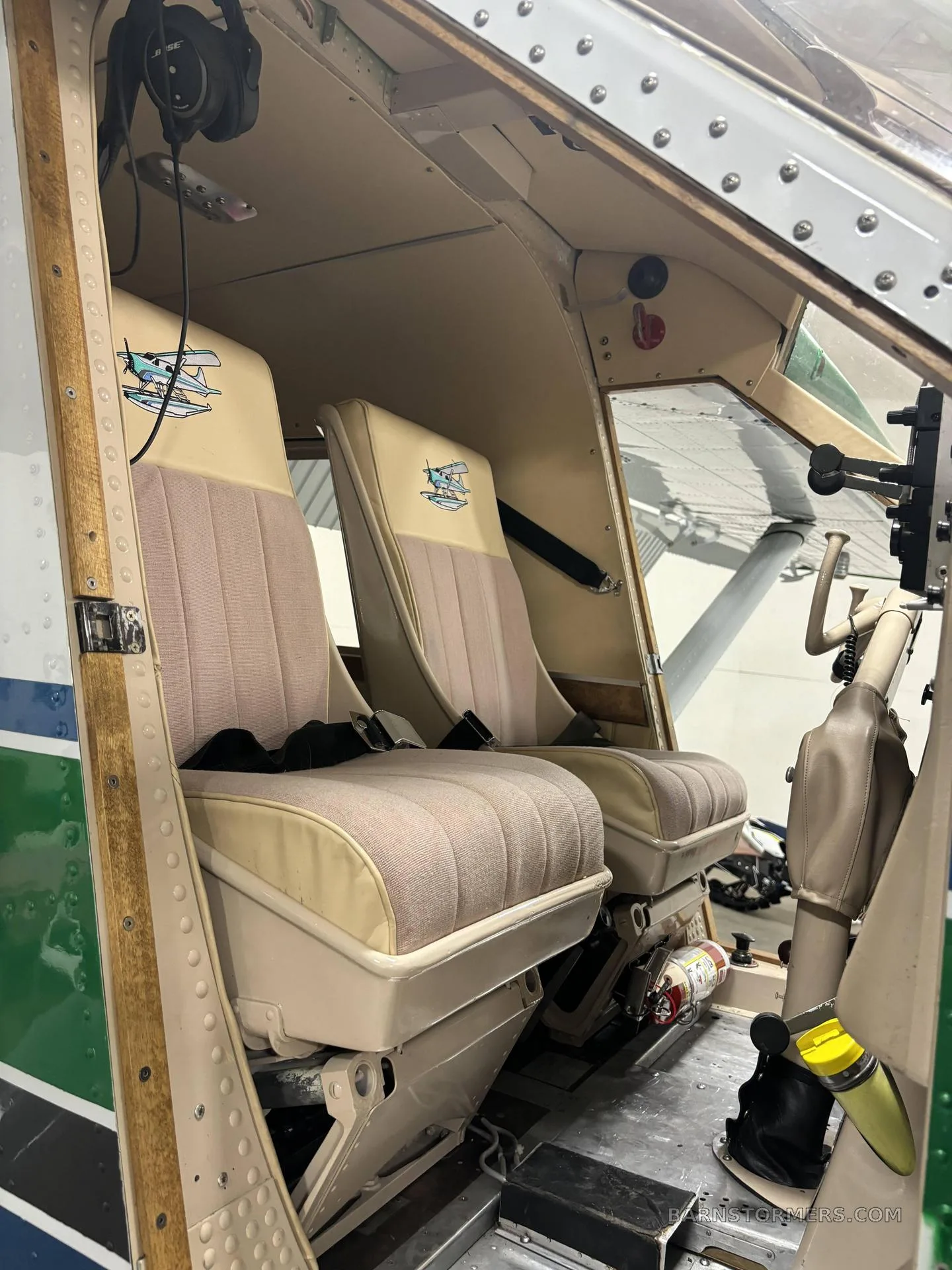
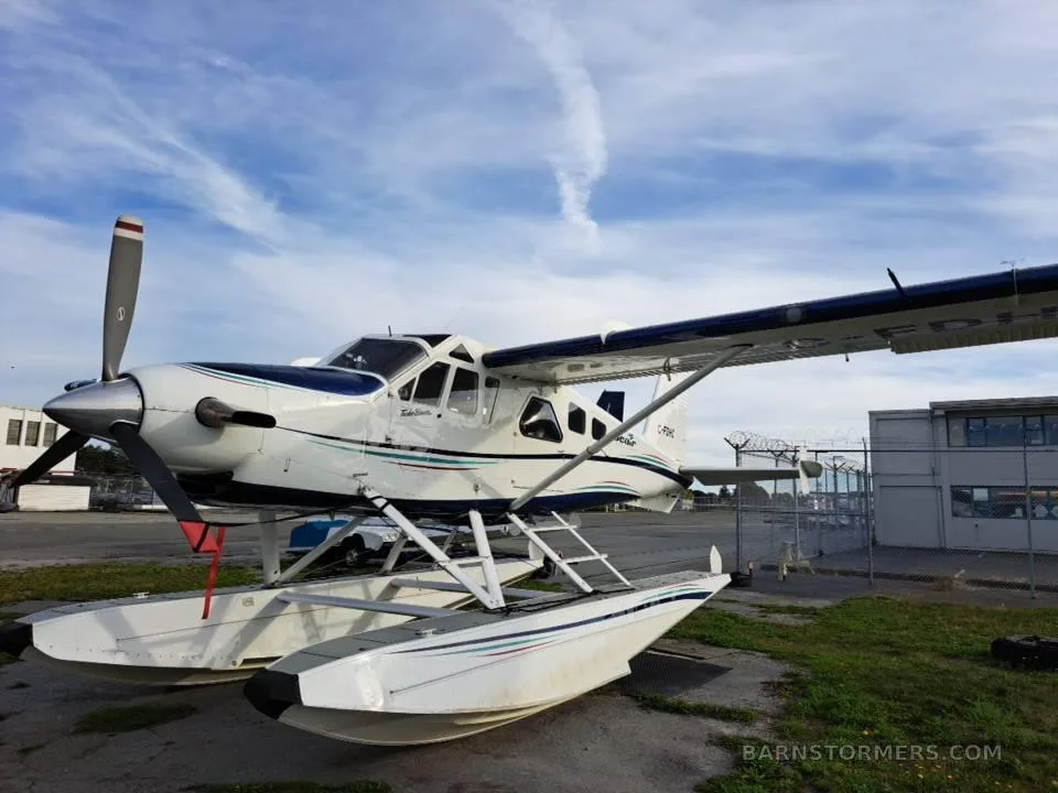
Free — save the DHC-2 to your watchlist and track it in one place.
More De Havilland DHC-2 MK IIImanuals & documents
Related documents
- Service Bulletin V2/0005De Havilland DHC-2 MK III · Service Bulletins
- SERVICE BULLETIN MANDATORYBeechcraft V35B Bonanza · Service Bulletins
- FALCON 900 MAINTENANCE MANUALDASSAULT FALCON 900EX · Maintenance Manual
- SERVICE BULLETIN MANDATORYBeechcraft G36 Bonanza · Service Bulletins
- Airworthiness Directive Schedule Aeroplanes Beechcraft F33, 35, V35 and A36 Series (Bonanza and Debonair)Beechcraft 33 Debonair · Service Bulletins
If you fly the De Havilland DHC-2 MK III, you may also be researching these.


In this document
Elevator Control Cable Assemblies
Inspect cables for corrosion, wear, and broken wires. Replace if bends or distortion are observed.
Elevator and Elevator Trim Control Cable Guide Pulleys
Check pulley bearings for corrosion and ensure they rotate freely. Replace if they do not.
Elevator Torque Tube Inspection
Inspect for surface paint and corrosion, focusing on attachment areas for wear and cracking.
Elevator Trim Tab Push Rod
Inspect for surface paint discontinuity and evidence of crevice corrosion.
Flap Torque Tube Assembly
Inspect for surface paint discontinuity and fretting corrosion at bearings.
Elevator Trim Screw Jack Assembly
Disassemble and clean for inspection of surface corrosion and internal parts.
Summary written by AI from the source document. Check the original before relying on it. See which parts of Sprinkle are written by AI.
Safety notes
- Replace cables with any internal corrosion or external wear involving two or more adjacent wires.
- Inspect for broken wires by passing a clean cloth along the cable length.
- Ensure control cables have the correct tension upon installation.
- Pay attention to bearings and cavities that can collect water and debris.
- Use a flashlight or borescope for internal inspections as needed.
- In severe corrosion environments, treat the interior of tubes with corrosion inhibiting compounds.
Summary written by AI from the source document. Check the original before relying on it. See which parts of Sprinkle are written by AI.
Full document text
DHC-2 BEAVER PART 2 - SPECIFIC SUPPLEMENTAL AND CORROSION INSPECTIONS C27–30–06 PAGE 1 C27–30–06 Elevator Trim Control Cable Assemblies, Fittings and Full Cable Lengths JAN 10/2019 C27–30–07 PAGE 0 DHC-2 BEAVER PART 2 - SPECIFIC SUPPLEMENTAL AND CORROSION INSPECTIONS ITEM: C27–30–07 Elevator Control Cable Assemblies, Fittings and Full Cable Lengths ATA CHAPTER: 27 – Flight Controls MANUAL REF: PSM 1–2–2, Part 2, Flight Controls, Fig. 2-20 and 2-22 PSM 1–2–4, Part 2, Fuselage Group, Fig. 53 PSM 1–2T–4, Part 2, Fuselage Group, Fig. 46 EFFECTIVITY: All REF DOCUMENTS: Nil ACCESS: Remove utility access panel (PSM 1-2-2, Fig. 1-3, Item 16). Remove access panel from cabin aft bulkhead. Remove tail cone (PSM 1-2-2, Fig. 1-3, Item 5). INSPECTION Detailed Visual Inspection (DVI) METHOD: INSPECTION 1) Cables for corrosion, wear, distortion, broken wires. OBJECTIVE: 2) Crevice corrosion, pitting, plating and/or paint degradation and surface corrosion at cable terminals, turnbuckles, and fork ends. RETREATMENT: Standard cables: AS REQUIRED, lubricate with MIL-PRF-81322 to maintain thin film of lubricant over the length of the cable. Corrosion resistant cable: NONE NOTES AND SPECIAL 1) Replace cables if bends, kinks, or distortion is observed. INSTRUCTIONS: 2) Inspect for broken wires by passing a clean, dry cloth along the entire length of the cable. A second person may be required to operate controls and provide access to the full length. If the cloth snags, remove the cable assembly for further inspection. For guidance and limitations on repair refer to PSM 1-2-2, Part 2, Paragraph 2.40.4. 3) Inspect entire length for corrosion. Where external corrosion or broken wires are found, remove the cable and inspect for internal corrosion, wear and broken wires. 4) Light external corrosion can be removed with a coarse weave cloth or a fibre brush. Re-protect after corrosion removal. 5) Replace cables with any internal corrosion and/or external wear that involves 2 or more adjacent wires. 6) Replace cables with pitted/cracked terminals or fork ends. 7) In the event that cables are removed for inspection and/or replacement, ensure the control cables have the correct tension on installation. Refer to PSM 1-2-2, Part 2, Paragraph 2.40.2 for tensioning instructions. JAN 10/2019 DHC-2 BEAVER PART 2 - SPECIFIC SUPPLEMENTAL AND CORROSION INSPECTIONS C27–30–07 PAGE 1 C27–30–07 Elevator Control Cable Assemblies, Fittings and Full Cable Lengths JAN 10/2019 C27–30–08 PAGE 0 DHC-2 BEAVER PART 2 - SPECIFIC SUPPLEMENTAL AND CORROSION INSPECTIONS ITEM: C27–30–08 Elevator and Elevator Trim Control Cable Guide Pulleys and Pulley Attachment Parts ATA CHAPTER: 27 – Flight Controls MANUAL REF: PSM 1–2–2, Part 2, Flight Controls, Fig. 2-20 and 2-22 PSM 1–2–4, Part 2, Fuselage Group, Fig. 53 and 55 PSM 1–2T–4, Part 2, Fuselage Group, Fig. 46 and 48 EFFECTIVITY: All REF DOCUMENTS: Nil ACCESS: Remove forward fuselage left hand, centre, and bottom access panels (PSM 1-2-2, Fig. 1-3, Items 18,19, 20). Remove rear cabin bulkhead access panel. Lift all floorboards. Remove cabin headliner panels. Remove trim control box cover. INSPECTION Detailed Visual Inspection (DVI) METHOD: INSPECTION 1) Pulley bearings for corrosion and loss of free movement. OBJECTIVE: 2) Pulley groove for debris, roughness, and wear. 3) Attachment brackets for deformation, cracking, degradation of coatings, pitting, and evidence of crevice corrosion. 4) Loose/working/broken bracket attachment fasteners. 5) Pulley pivot pin/bolt and hardware for loss of plating, surface, and crevice corrosion. RETREATMENT: AS REQUIRED, re-treat attachment brackets only as per Part 1, Paragraph 7. NOTES AND SPECIAL 1) Refer to PSM 1-2-2, Part 2, Paragraph 2.40.3. for pulley cleaning instructions. INSTRUCTIONS: 2) Operate cables through full range to observe pulley motion and cable groove surfaces. Replace pulleys that do not rotate freely with cable motion. JAN 10/2019 DHC-2 BEAVER PART 2 - SPECIFIC SUPPLEMENTAL AND CORROSION INSPECTIONS C27–30–08 PAGE 1 C27–30–08 Elevator and Elevator Trim Control Cable Guide Pulleys and Pulley Attachment Parts JAN 10/2019 C27–30–09 PAGE 0 DHC-2 BEAVER PART 2 - SPECIFIC SUPPLEMENTAL AND CORROSION INSPECTIONS ITEM: C27–30–09 Elevator Torque Tube and Trim Torque Tube Accessible Surfaces and Attachment Parts ATA CHAPTER: 27 – Flight Controls MANUAL REF: PSM 1–2–2, Part 2, Flight Controls, Fig. 2-22 PSM 1–2–4, Part 2, Empennage Group, Fig.10 PSM 1–2T–2, Part 2, Supplement 6 PSM 1–2T–4, Part 2, Empennage Group, Fig.8 EFFECTIVITY: All REF DOCUMENTS: Nil ACCESS: Remove tail cone (PSM 1-2-2, Fig. 1-3, Item 5). INSPECTION Detailed Visual Inspection (DVI) METHOD: INSPECTION 1) Surface paint and plating discontinuity/blistering and corrosion. OBJECTIVE: 2) Crevice corrosion, wear, cracking at attachments. RETREATMENT: RE-PROTECT as per Part 1, Paragraph 7. NOTES AND SPECIAL None INSTRUCTIONS: JAN 10/2019 DHC-2 BEAVER PART 2 - SPECIFIC SUPPLEMENTAL AND CORROSION INSPECTIONS C27–30–09 PAGE 1 C27–30–09 Elevator Torque Tube and Trim Torque Tube Accessible Surfaces and Attachment Parts JAN 10/2019 C27–30–10 PAGE 0 DHC-2 BEAVER PART 2 - SPECIFIC SUPPLEMENTAL AND CORROSION INSPECTIONS ITEM: C27–30–10 Elevator Torque Tube and Trim Torque Tube End Plates and Interior Surfaces ATA CHAPTER: 27 – Flight Controls MANUAL REF: PSM 1–2–2, Part 2, Flight Controls, Fig. 2-22 PSM 1–2–4, Part 2, Empennage Group, Fig. 10 PSM 1–2T–2, Part 2, Supplement 6 PSM 1–2T–4, Part 2, Empennage Group, Fig. 9 EFFECTIVITY: All REF DOCUMENTS: SB 2/47, Rev E or later, Stabilizers - Special Inspection for Cracks in the Front Spar of the Horizontal Stabilizer SB 2/30, Rev NC or later, Flight Controls - Elevator Root Rib - Inspection for Cracking and Replacement. ACCESS: Remove tail cone (PSM 1-2-2, Fig. 1-3, Item 5). Remove left and right-hand elevators (PSM 1-2-2, Part 2).
Show full textShow less
Use flashlight or borescope, as required, to inspect interior of tube. INSPECTION Detailed Visual Inspection (DVI) METHOD: INSPECTION Surface coating or paint discontinuity, surface corrosion and pitting. OBJECTIVE: RETREATMENT: RE-PROTECT as per Part 1, Paragraph 7. NOTES AND SPECIAL 1) Can be coordinated with horizontal stabilizer inspection or elevator root rib INSTRUCTIONS: inspection (see ref. documents, above). 2) Refer to Part 1, Paragraph 6.C.(2)(c) for recommended surface treatment for interior portion of the tube. JAN 10/2019 DHC-2 BEAVER PART 2 - SPECIFIC SUPPLEMENTAL AND CORROSION INSPECTIONS C27–30–10 PAGE 1 C27–30–10 Elevator Torque Tube and Trim Torque Tube End Plates and Interior Surfaces JAN 10/2019 C27–30–11 PAGE 0 DHC-2 BEAVER PART 2 - SPECIFIC SUPPLEMENTAL AND CORROSION INSPECTIONS ITEM: C27–30–11 Elevator Front Connecting Rod ATA CHAPTER: 27 – Flight Controls MANUAL REF: PSM 1–2T–2, Supplement 6, Fig. 6-6 PSM 1–2T–4, Fuselage Group, Fig. 46 EFFECTIVITY: MK lll REF DOCUMENTS: Nil ACCESS: Access per PSM 1-2T-2, Supplement 6, Paragraph 6.19.C. All surfaces must be visible with 10x magnification, remove as required. INSPECTION Detailed Visual Inspection (DVI) - Use 10x magnification and a strong light source. METHOD: INSPECTION 1) Surface paint blistering, flaking, or cracking. OBJECTIVE: 2) Evidence of corrosion or cracking, particularly at mating parts/surfaces. 3) Corrosion at bearings. 4) Loose rivets at ends of the rod. 5) Corrosion or loss of plating on steel parts (rod ends). RETREATMENT: AS REQUIRED, re-protect as per Part 1, Paragraph 7. NOTES AND SPECIAL Blistered, flaked or cracked surface finish should be removed locally as per Part 1, INSTRUCTIONS: Paragraph 5.C., to inspect for underlying corrosion and cracking. Re-protect as per Part 1, Paragraph 7. JAN 10/2019 DHC-2 BEAVER PART 2 - SPECIFIC SUPPLEMENTAL AND CORROSION INSPECTIONS C27–30–11 PAGE 1 C27–30–11 Elevator Front Connecting Rod JAN 10/2019 C27–30–12 PAGE 0 DHC-2 BEAVER PART 2 - SPECIFIC SUPPLEMENTAL AND CORROSION INSPECTIONS ITEM: C27–30–12 Elevator Trim Tab Push Rod ATA CHAPTER: 27 – Flight Controls MANUAL REF: PSM 1–2–2, Part 2, Flight Controls, Fig. 2-22 PSM 1–2–4, Part 2, Empennage Group, Fig.10 PSM 1–2T–2, Supplement 6 PSM 1–2–4, Part 2, Empennage Group, Fig. 9 EFFECTIVITY: All REF DOCUMENTS: Nil ACCESS: Remove tail cone (PSM 1-2-2, Fig. 1-3, Item 5). INSPECTION Detailed Visual Inspection (DVI) METHOD: INSPECTION 1) Surface paint discontinuity and corrosion. OBJECTIVE: 2) Evidence of crevice corrosion. 3) Bearing corrosion and wear. 4) Cracking at or loose rivets. RETREATMENT: RE-PROTECT as per Part 1, Paragraph 7. NOTES AND SPECIAL None INSTRUCTIONS: JAN 10/2019 DHC-2 BEAVER PART 2 - SPECIFIC SUPPLEMENTAL AND CORROSION INSPECTIONS C27–30–12 PAGE 1 C27–30–12 Elevator Trim Tab Push Rod JAN 10/2019 C27–30–13 PAGE 0 DHC-2 BEAVER PART 2 - SPECIFIC SUPPLEMENTAL AND CORROSION INSPECTIONS ITEM: C27–30–13 Elevator Trim Screw Jack Assembly ATA CHAPTER: 27 – Flight Controls MANUAL REF: PSM 1–2–4, Part 2, Empennage Group, Fig. 10 PSM 1–2T–4, Part 2, Empennage Group, Fig. 9 EFFECTIVITY: All REF DOCUMENTS: Nil ACCESS: Remove tail cone (PSM 1-2-2, Fig. 1-3, Item 5). INSPECTION Detailed Visual Inspection (DVI) - Remove, disassemble and clean as METHOD: per PSM 1-2-2, Paragraph 2.46. INSPECTION 1) Surface corrosion, crevice corrosion and pitting. OBJECTIVE: 2) Fretting corrosion on cable drum. 3) Bearing corrosion and wear. 4) Corrosion and wear of internal parts. RETREATMENT: External grease cable drum. Lubricate internal parts as per PSM 1-2-2, Part 1, Paragraph 2.46.5. NOTES AND SPECIAL Housing has many cavities that can collect water and debris. Pay particular INSTRUCTIONS: attention to bearings, bottoms of cavities, and the region around the retaining ring. JAN 10/2019 DHC-2 BEAVER PART 2 - SPECIFIC SUPPLEMENTAL AND CORROSION INSPECTIONS C27–30–13 PAGE 1 C27–30–13 Elevator Trim Screw Jack Assembly JAN 10/2019 C27–50–01 PAGE 0 DHC-2 BEAVER PART 2 - SPECIFIC SUPPLEMENTAL AND CORROSION INSPECTIONS ITEM: C27–50–01 Flap Torque Tube Assembly ATA CHAPTER: 27 – Flight Controls MANUAL REF: PSM 1–2–2, Part 2, Flight Controls, Fig. 2-27 PSM 1–2–4, Part 2, Fuselage Group, Fig. 47 PSM 1–2–2T–2, Supplement 6 PSM 1–2T–4, Part 2, Fuselage Group, Fig. 41 EFFECTIVITY: All REF DOCUMENTS: Nil ACCESS: Remove cabin headliner. Remove excess grease at bearings. Remove wing root fairings; remove debris from inner surface of tube at both ends. Use mirror or borescope and strong light source. INSPECTION Detailed Visual Inspection (DVI) METHOD: INSPECTION 1) Surface paint discontinuity, blistering and corrosion. OBJECTIVE: 2) Evidence of fretting corrosion at bearings. 3) Surface corrosion and pitting of inner tube surfaces. RETREATMENT: AS REQUIRED, re-protect interior and exterior non-lubricated tube surfaces as per Part 1, Paragraph 7. Lubricate bearings as per PSM 1-2-2, Part 1, Lubrication Diagram Figure 1-10. NOTES AND SPECIAL In severe corrosion (refer to Part 1, Paragraph 4.C.) environments, treat full length INSTRUCTIONS: of interior of tube with water displacing corrosion inhibiting compound as per Part 1, Paragraph 7. JAN 10/2019 DHC-2 BEAVER PART 2 - SPECIFIC SUPPLEMENTAL AND CORROSION INSPECTIONS C27–50–01 PAGE 1 C27–50–01 Flap Torque Tube Assembly JAN 10/2019 C27–50–02 PAGE 0 DHC-2 BEAVER PART 2 - SPECIFIC SUPPLEMENTAL AND CORROSION INSPECTIONS ITEM: C27–50–02 Flap Control Rods ATA CHAPTER: 27 – Flight Controls MANUAL REF: PSM 1–2–2, Part 2, Flight Controls, Fig. 2-27 PSM 1–2–4, Part 2, Fuselage Group, Fig. 47 PSM 1–2T–2, Supplement 6 PSM 1–2T–4, Fuselage Group, Fig. 41 EFFECTIVITY: All REF DOCUMENTS: Nil ACCESS: Remove lower wing root fairing (PSM 1-2-2, Fig. 1-3, Item 17). INSPECTION Detailed Visual Inspection (DVI) METHOD: INSPECTION 1) Surface paint or plating discontinuity, blistering and corrosion. OBJECTIVE: 2) Corrosion and wear of bearings. 3) Evidence of crevice corrosion. RETREATMENT: RE-PROTECT as per Part 1, Paragraph 7 NOTES AND SPECIAL Corrosion is most often found at the exposed end of the control rod, nearest the flap. INSTRUCTIONS: JAN 10/2019 DHC-2 BEAVER PART 2 - SPECIFIC SUPPLEMENTAL AND CORROSION INSPECTIONS C27–50–02 PAGE 1 C27–50–02 Flap Control Rods JAN 10/2019 C32–46–01 PAGE 0 DHC-2 BEAVER PART 2 - SPECIFIC SUPPLEMENTAL AND CORROSION INSPECTIONS ITEM: C32–46–01 Ski Link and Attachment Bolts, Link-to-Ski and Link-to-Actuator ATA CHAPTER: 32 – Landing Gear MANUAL REF: PSM 1–2–4, Special Order Group, Fig. 83 EFFECTIVITY: Wheel-Ski Installations REF DOCUMENTS: Nil ACCESS: Disassemble link from ski, actuator, and axle. INSPECTION Detailed Visual Inspection (DVI) - Use 10x magnification and strong light source. METHOD: INSPECTION 1) Surface finish degradation, flaking, cracking, blistering, surface corrosion. OBJECTIVE: 2) Evidence of corrosion on/in link. Pay particular attention to bushings, areas around drive screws. 3) Loose or missing drive screws. 4) Cracking. Pay particular attention to undercuts, threads, radius changes on bolts. 5) Excessive free play. RETREATMENT: LUBRICATE at all bolt/bushing locations with general low temperature lubricating grease on assembly. AS REQUIRED re-protect internal surfaces by flushing with corrosion preventive compound (ref. Part 1, Paragraph 6.C.(2)(c)) NOTES AND SPECIAL 1) If corrosion is found or suspected at drive screws, or screws are loose or INSTRUCTIONS: missing, internal corrosion may be present. 2) Remove light corrosion on link and re-protect as Part 1, Paragraph 6.D. If moderate to severe corrosion is found, replace. 3) Refer to PSM 1-2-2, Part 1, Fig.1-10 for lubricants. 4) Replace cracked or damaged bolts. JAN 10/2019 DHC-2 BEAVER PART 2 - SPECIFIC SUPPLEMENTAL AND CORROSION INSPECTIONS C32–46–01 PAGE 1 C32–46–01 Ski Link and Attachment Bolts, Link-to-Ski and Link-to-Actuator JAN 10/2019 C53–10–01 PAGE 0 DHC-2 BEAVER PART 2 - SPECIFIC SUPPLEMENTAL AND CORROSION INSPECTIONS ITEM: C53–10–01 Forward Fuselage Tubular Frame “Birdcage” ATA CHAPTER: 53 – Fuselage MANUAL REF: PSM 1–2–2, Part 2, Fig. 2-20 & Fig. 2-24 PSM 1–2–3, Fuselage Group, Fig. 4-4 PSM 1–2–4, Fuselage Group, Fig. 25 & 26 PSM 1–2T–4, Fuselage Group, Fig. 23 EFFECTIVITY: All REF DOCUMENTS: SB 2/49, Rev C or later (MK l and MK II) or TB/57, Rev D or later (MK lll), Fuselage - Forward Tubular Frame - Inspection for Corrosion and Repair. ACCESS: Remove fuselage access panels under cockpit (ref. PSM 1-2-2, Part 1, Fig. 1-3 or PSM 1-2T-2, Supplement 6, Fig.6-3). INSPECTION Detailed Visual Inspection (DVI) - Clean as per Part 1, Paragraph 5.D. Use a plastic METHOD: scraper to remove any loose paint or primer. Use borescope, mirror, strong light source, and 10x magnification to view all external surfaces. INSPECTION 1) Surface finish degradation, blistering, cracking, flaking. OBJECTIVE: 2) Surface corrosion. 3) Cracking. Pay particular attention to welded joints, elevator and rudder stops, forward fuselage strut mounting points, webbed plate tie bar mounting points. 4) Loose or missing drive screws, drive screws ‘leaking’ corrosion. This may indicate internal corrosion. RETREATMENT: RE-PROTECT as per Part 1, Paragraph 7. NOTES AND SPECIAL 1) If surface finish is cracked or damaged, locally remove finish to inspect for surface INSTRUCTIONS: corrosion and cracking on the frame. Remove light corrosion, apply cold galvanizing compound (min 93% zinc) and restore surface finish as per Part 1, Paragraph 6.C.(2)(b). Re-protect as per Part 1, Paragraph 7. 2) Measure thickness after corrosion removal by ultrasonic thickness check as per SB 2/49 or TB/57. Tube must meet the minimum thickness requirements of SB 2/49 or TB/57 after corrosion removal. 3) Refer to SB 2/49 or TB/57 for repair instructions if thickness is below minimum. 4) If loose, missing, or corroded drive screw(s) are found, remove screw(s), remove light corrosion, and locally ultrasonic thickness check as per SB 2/49 or TB/57. If wall thickness is within limits, re-protect internal surfaces by spraying with corrosion preventive compound (LPS 3 or equivalent). Re-install drive screws wet with sealant as per Part 1, Paragraph 6.D. Re-protect as per Part 1, Paragraph 7. 5) If evidence of cracking is found, locally remove surface finish as per Part 1, Paragraph 5, and inspect for cracks using fluorescent dye penetrant as per ASTM E1417 (Type 1) or magnetic particle inspection as per ASTM E1444. If no cracks are found, restore surface finish as per Note 1), above. If cracks are found, repair as per SB 2/49 (MK l and MK II) or TB/57 (MK lll). JAN 10/2019 DHC-2 BEAVER PART 2 - SPECIFIC SUPPLEMENTAL AND CORROSION INSPECTIONS C53–10–01 PAGE 1 C53–10–01 Forward Fuselage Tubular Frame “Birdcage” JAN 10/2019 C53–10–02 PAGE 0 DHC-2 BEAVER PART 2 - SPECIFIC SUPPLEMENTAL AND CORROSION INSPECTIONS ITEM: C53–10–02 Forward Fuselage Tubular Frame “Birdcage”, Thickness Check ATA CHAPTER: 53 – Fuselage MANUAL REF: PSM 1–2–2, Part 2, Fig. 2-20 & Fig. 2-24 PSM 1–2–3, Fuselage Group, Fig. 4-4 PSM 1–2–4, Fuselage Group, Fig. 25 & 26 PSM 1–2T–4, Fuselage Group, Fig. 23 EFFECTIVITY: All REF DOCUMENTS: SB 2/49, Rev C or later (MK l and MK II), or TB/57, Rev D or later (MK lll), Fuselage - Forward Tubular Frame - Inspection for Corrosion and Repair. ACCESS: Prepare for inspection as per SB 2/49 or TB/57. INSPECTION Non-Destructive Inspection (NDI) - Accomplish ultrasonic thickness test as per METHOD: SB 2/49 or TB/57, as applicable. INSPECTION Corrosion thickness loss. OBJECTIVE: RETREATMENT: RE-PROTECT as per Part 1, Paragraph 7. NOTES AND SPECIAL Refer to SB 2/49 (MK l/ll) or TB/57 (MK lll) for thickness limits, repair instructions, INSTRUCTIONS: and close-out. JAN 10/2019 DHC-2 BEAVER PART 2 - SPECIFIC SUPPLEMENTAL AND CORROSION INSPECTIONS C53–10–02 PAGE 1 C53–10–02 Forward Fuselage Tubular Frame “Birdcage”, Thickness Check JAN 10/2019 C53–40–01 PAGE 0 DHC-2 BEAVER PART 2 - SPECIFIC SUPPLEMENTAL AND CORROSION INSPECTIONS ITEM: C53–40–01 Webbed Plate and Tie Bars (STA -16.00) ATA CHAPTER: 53 – Fuselage MANUAL REF: PSM 1–2–4, Fuselage Group, Fig.16 PSM 1–2T–4, Fuselage Group, Fig. 21 EFFECTIVITY: All REF DOCUMENTS: Nil ACCESS: Remove LH and RH landing gear/front float strut fairings. Remove belly access panels adjacent to the firewall. INSPECTION Detailed Visual Inspection (DVI) - Use magnification and strong light source. METHOD: Use borescope to view surfaces that are difficult to reach, including top and bottom of tie bar ends when landing gear are installed. INSPECTION 1) Surface finish degradation, blistering, cracking, flaking. OBJECTIVE: 2) Surface corrosion and pitting. Pay particular attention to areas around bushings at forward fuselage frame (‘Birdcage’) and float fitting/landing gear attachment points. 3) Excessive free play at the tie bar ends. 4) Cracked, damaged, missing sealant around bushings. 5) Corrosion product at landing gear/float strut/forward fuselage frame (‘Birdcage’) attachments indicating crevice or fretting corrosion at bushings/attachment bolts. 6) Evidence of seized landing gear/float strut attachment bolts. RETREATMENT: RE-PROTECT as per Part 1, Paragraph 7. For areas around landing gear/float strut attachment bolts, ensure they are thoroughly clear of debris so that the compound can freely wick into the joint. AS REQUIRED - seal accessible bushing edges as per Part 1, Paragraph 6.D. NOTES AND SPECIAL 1) If there is a large amount of stubborn dirt/debris or corrosion product around INSTRUCTIONS: any of the attachment bolts, if excessive free play is found, or if bolts are found/ suspected to be seized, disassemble as per PSM 1-2-2, Part 2 for further cleaning and inspection of tie bar(s) and attachment bolts for damage and corrosion. 2) Replace corroded, worn or damaged attachment parts. Repair/replace webbed plate and tie bars as per PSM 1-2-3, Section IV, Paragraph 4.8.1. 3) On reassembly of landing gear/float strut: a) Seal edges around bushing as per Part 1, Paragraph 6.D. b) Wet install landing gear/float strut attachment bolts as per PSM 1-2-2, Part 2, Paragraph 2.20.8 and 2.32.5. JAN 10/2019 DHC-2 BEAVER PART 2 - SPECIFIC SUPPLEMENTAL AND CORROSION INSPECTIONS C53–40–01 PAGE 1 C53–40–01 Webbed Plate and Tie Bars (STA - 16.00) JAN 10/2019 C53–40–02 PAGE 0 DHC-2 BEAVER PART 2 - SPECIFIC SUPPLEMENTAL AND CORROSION INSPECTIONS ITEM: C53–40–02 Fuselage Fittings, Landing Gear/Float Strut/Wing Strut Attachment (STA 8.00) ATA CHAPTER: 53 – Fuselage MANUAL REF: PSM 1–2–4, Fuselage Group, Fig.16 PSM 1–2T–4, Fuselage Group, Fig. 21 EFFECTIVITY: All REF DOCUMENTS: C2Z3101, Fitting Assembly, Attachment - Undercarriage and Wing Strut Pickup on Fuselage, Retrofit Installation. VALBVS1256-27, DHC-2 MK I 5600 lb Gross Weight Increase, Installation Instructions. VALTB1200-27, DHC-2 MK III Turbo Beaver 6000 lb Gross Weight Increase Kit, Installation Instructions. ACCESS: Remove LH and RH lower wing cuff, main landing gear or float fairings to access external portion of fitting. Remove LH and RH cabin seats and floorboards. INSPECTION METHOD: Detailed Visual Inspection (DVI) - Use magnification and strong light source. INSPECTION 1) Surface finish degradation, blistering, cracking, flaking. OBJECTIVE: 2) Surface corrosion and pitting. Pay particular attention to areas around bushings and landing gear/float strut/wing strut attachments. 3) Excessive free play at landing gear/float strut/wing strut attachment points. 4) Cracked, damaged, or missing sealant around bushings. 5) Corrosion product at landing gear/float strut/wing strut attachments indicating crevice or fretting corrosion at bushings/attachment bolts. 6) Evidence of seized attachment bolts. RETREATMENT: RE-PROTECT as per Part 1, Paragraph 7. For areas around landing gear/float strut/ wing strut attachment bolts, ensure they are thoroughly clear of debris so that the compound can freely wick into the joint. AS REQUIRED restore sealant around bushing edges as per Part 1, Paragraph 6.D. NOTES AND SPECIAL 1) If there is a large amount of stubborn dirt/debris or corrosion product around any INSTRUCTIONS: of the landing gear/float strut/ wing strut attachment bolts, or if bolts are found/ suspected to be seized, disassemble as per PSM 1-2-2, Part 2, for further cleaning and inspection of fitting, wire pull (if present), and attachment bolts for damage and corrosion. Replace corroded, worn or damaged attachment parts and/or fittings. 2) On reassembly of landing gear/float strut/wing strut: a) Seal edges around bushings as per Part 1, Paragraph 6.D. b) Wet install landing gear/float strut/wing strut attachment bolts as per PSM 1-2-2, Part 2, Paragraph 2.32.5 and/or 2.20.8. 3) Replace worn or damaged fittings as per: a) C2Z3101 for P/N C2FS419A, C2FS475A, or C2FS5487A. b) VALBVS1256-27 for P/N VALTBS1209-1 installed on MK I aircraft. c) VALTB1200-27 for P/N VALTBS1209-1 installed on MK III aircraft. 4) When replacing worn or damaged fittings, clean away any dirt or debris from the fuselage where the fitting is installed and inspect for corrosion. JAN 10/2019 DHC-2 BEAVER PART 2 - SPECIFIC SUPPLEMENTAL AND CORROSION INSPECTIONS C53–40–02 PAGE 1 C53–40–02 Fuselage Fittings, Landing Gear/Float Strut/Wing Strut Attachment (STA 8.00) JAN 10/2019 C55–10–01 PAGE 0 DHC-2 BEAVER PART 2 - SPECIFIC SUPPLEMENTAL AND CORROSION INSPECTIONS ITEM: C55–10–01 Horizontal Stabilizer (Tailplane), Structure and Skin ATA CHAPTER: 55 – Stabilizers MANUAL REF: PSM 1–2–3, Part 3, Tail Group, Fig. 3-1 PSM 1–2–4, Tail Group, Fig. 9 PSM 1-2T-4, Empennage Group, Fig.12 EFFECTIVITY: All REF DOCUMENTS: SB 2/47, Rev E or later, Stabilizers - Special Inspection for Cracks in the Front Spar of the Horizontal Stabilizer (and Rectification). ACCESS: Remove the tail cone (ref. PSM 1-2-2, Part 2, Paragraph 2.16.1). Optionally remove elevators and/or horizontal stabilizer (ref. PSM 1-2-2, Part 2, Paragraph 2.17.1 and Paragraph 2.18.1). INSPECTION Detailed Visual Inspection (DVI) - Use flexible borescope through inspection METHOD: access points, tooling holes, lightening holes on rib webs and spars. INSPECTION 1) Cracking. Pay particular attention to structure around fastener holes and OBJECTIVE: open holes at the following areas: a) Spar and skin splices/joints. b) Rib and former flanges at attachments, bending radii. c) Access cutouts and lightening holes on ribs, spars. d) Mounting, hinge, pickup and attachment brackets and plates. e) Gusset plate on aft side of front spar. 2) Evidence of loose or “smoking” rivets. 3) Loose elevator mounting hinge brackets and plates. 4) Evidence of corrosion between mounting brackets and front/rear spars. RETREATMENT: RE-PROTECT as per Part 1, Paragraph 7. NOTES AND SPECIAL 1) Can be coordinated with front spar inspection as per SB 2/47. INSTRUCTIONS: 2) If evidence of cracking is found, disassemble and inspect by fluorescent dye penetrant (refer to SB 2/47 for NDI technique). Replace cracked or unserviceable parts before next flight. Replace gusset plates if cracks are found on the gusset or if the front spar is replaced (refer to SB 2/47 for rectification of front spar in case of cracking). 3) If evidence of corrosion behind mounting bracket(s) is found, remove affected bracket(s) for further inspection. 4) If loose mounting bracket(s) is/are found, remove and fluorescent dye penetrant inspect around attachment holes on the stabilizer structure (refer to SB 2/47 for NDI technique). 5) If elevators and/or horizontal stabilizer are removed, check for correct movement of controls on re-installation as per PSM 1-2-2, Part 2, Paragraphs 2.43 and 2.44. JAN 10/2019 DHC-2 BEAVER PART 2 - SPECIFIC SUPPLEMENTAL AND CORROSION INSPECTIONS C55–10–01 PAGE 1 C55–10–01 Horizontal Stabilizer (Tailplane), Structure and Skin JAN 10/2019 C55–10–02 PAGE 0 DHC-2 BEAVER PART 2 - SPECIFIC SUPPLEMENTAL AND CORROSION INSPECTIONS ITEM: C55–10–02 Front Horizontal Stabilizer (Tailplane) Pick-up Brackets ATA CHAPTER: 55 – Stabilizers MANUAL REF: PSM 1–2–4, Tail Group, Fig. 9 PSM 1–2T–4, Empennage Group, Fig.12 EFFECTIVITY: All REF DOCUMENTS: Technical News Sheet Series B No.49, Overtightening of Attachment Bolts in Tailplane Front Spar Attachment Brackets. Technical News Sheet Series B No.55, Beaver Tailplane to Fuselage Front Joint Cracks in Tailplane Front Spar. SB 2/47, Rev E or later, Stabilizers - Special Inspection for Cracks in the Front Spar of the Horizontal Stabilizer (and Rectification). ACCESS: Remove the tail cone (ref. PSM 1-2-2, Part 2, Paragraph 2.16.1). Remove horizontal stabilizer (ref. PSM 1-2-2, Part 2, Paragraph 2.18.1) and disassemble front pick-up bracket from the forward spar. Access attachment nuts from the lightening holes on the rear spar. INSPECTION Non-Destructive Inspection (NDI) - After removing bracket, packing plate, and METHOD: washer plate, use borescope to inspect gusset. Use fluorescent dye penetrant as per ASTM E1417 (Type 1) or Standard High Frequency Eddy Current (SHFEC) as per Appendix C, Paragraph 3, to inspect bracket and washer plate. INSPECTION 1) Cracking on brackets, packing plates, and washer plate (NDI). Pay particular OBJECTIVE: attention to areas around attachment holes and bushings. 2) Surface corrosion and pitting on bracket body, bushings, washer plate, packing, attachment parts. 3) Elongated holes on bracket, washer plate, and packing. 4) Cracking on gussets (borescope). Pay particular attention to fastener holes, and areas at the top and bottom of the washer plate. RETREATMENT: RE-PROTECT as per Part 1, Paragraph 7. NOTES AND SPECIAL 1) Can be coordinated with horizontal stabilizer inspection SB 2/47. INSTRUCTIONS: 2) Remove light corrosion and re-protect before further flight. Brackets with moderate to severe corrosion shall be replaced before further flight. 3) Replace cracked or unserviceable parts before further flight. 4) Refer to TNS B49 and B55 for appropriate installation torque values. 5) On re-installation, re-secure bolt to fitting with locking wire. Re-install tail cone and check for proper operation of flight controls as per PSM 1-2-2, Part 2, Paragraphs 2.43 and 2.44. JAN 10/2019 DHC-2 BEAVER PART 2 - SPECIFIC SUPPLEMENTAL AND CORROSION INSPECTIONS C55–10–02 PAGE 1 C55–10–02 Front Horizontal Stabilizer (Tailplane) Pick-up Bracket Assembly JAN 10/2019 C55–20–01 PAGE 0 DHC-2 BEAVER PART 2 - SPECIFIC SUPPLEMENTAL AND CORROSION INSPECTIONS ITEM: C55–20–01 Elevator Torque Tube Root Rib Attachment Bolts ATA CHAPTER: 55 – Elevators MANUAL REF: PSM 1–2–4, Part 2, Empennage Group, Fig. 10 PSM 1–2T–4, Part 2, Empennage Group, Fig. 9 EFFECTIVITY: All REF DOCUMENTS: SB 2/47, Rev E or later, Stabilizers - Special Inspection for Cracks in the Front Spar of the Horizontal Stabilizer. SB 2/30, Rev NC or later, Flight Controls - Elevator Root Rib - Inspection for Cracking and Replacement. ACCESS: Remove tail cone (PSM 1-2-2, Fig. 1-3, Item 5). Remove left and right-hand elevators (PSM 1-2-2, Part 2, Paragraph 2.45). INSPECTION Detailed Visual Inspection (DVI) METHOD: INSPECTION 1) Surface plating or paint discontinuity and corrosion. OBJECTIVE: 2) Evidence of crevice corrosion. RETREATMENT: RE-PROTECT as per Part 1, Paragraph 7. NOTES AND SPECIAL Can be coordinated with horizontal stabilizer inspection or elevator root rib inspection INSTRUCTIONS: (SB 2/47 or SB 2/30). In the case of rotational movement of bolt, an indicator of corrosion of the bolt or anchor plate inside the elevator at the root rib, disassemble the root rib (ref. SB 2/30 for disassembly instructions). If moderate to severe corrosion exists around the root rib torque tube attachment bolts, disassemble the root rib, remove anchor plate and inspect for crevice corrosion, pitting, surface corrosion, paint discontinuity. JAN 10/2019 DHC-2 BEAVER PART 2 - SPECIFIC SUPPLEMENTAL AND CORROSION INSPECTIONS C55–20–01 PAGE 1 C55–20–01 Elevator Torque Tube Root Rib Attachment Bolts JAN 10/2019 C55–20–02 PAGE 0 DHC-2 BEAVER PART 2 - SPECIFIC SUPPLEMENTAL AND CORROSION INSPECTIONS ITEM: C55–20–02 Elevator Mass Balance ATA CHAPTER: 55 – Elevators MANUAL REF: PSM 1–2–2, Part 2, Flight Controls, Fig. 3 -1 PSM 1–2–4, Part 2, Fuselage Group, Fig. 10 PSM 1–2T–2, Supplement 6 PSM 1–2T–4, Part 2, Fuselage Group, Fig. 9 EFFECTIVITY: All REF DOCUMENTS: MK l/ll SB 2/50, Rev NC or later, Stabilizers - Installation of Access Cover and Special Inspection for the Elevator Mass Balance Weight for Separation - Modification 2/1540. MK lll TB/58, Rev NC or later, Stabilizers - Installation of Access Cover and Special Inspection of the Elevator Mass Balance Weight for Separation - Modification T2/2079. ACCESS: Remove elevator mass balance access panels. Remove and retain balance weights as per SB 2/50 or TB/58, as applicable. INSPECTION METHOD: Detailed Visual Inspection (DVI) - Inspect with 10x magnification, mirror, and strong light. INSPECTION 1) Surface paint discontinuity and surface corrosion on elevator tip structure OBJECTIVE: under and around lead mass balance weights. 2) Corrosion and loss of plating on attachment parts. 3) Security of mass balance. RETREATMENT: RE-PROTECT elevator supporting structure and mass balance weights separately as per Part 1, Paragraph 7. Use light film (Grade 3) corrosion inhibiting compound or corrosion inhibiting jointing compound. After assembly apply corrosion inhibiting compound to exposed fasteners as per Part 1, Paragraph 7.B. NOTES AND SPECIAL 1) Refer to SB 2/50 or TB/58, as applicable, for corrosion repair limits. INSTRUCTIONS: 2) After repair, check balance of elevator as per PSM 1-2-3, Section 1, Paragraph 1.19 and Figure 1-7, or PSM 1-2T-2, Supplement 6, Paragraph 6.12A.4. 3) If moderate or severe corrosion is observed under/around the elevator mass balance, inspect the rudder mass balance and supporting structure: a) Disassemble rudder tip fairing and disassemble rudder mass balance. b) Inspect rudder tip rib, packing plate, and fasteners for corrosion, cracking. c) Repair tip rib, as required, as per PSM 1-2-3, Section 3, Paragraph 3.10 through 3.13. d) Restore surface finish of rib, packing plate, and mass balance as per Part 1, Paragraph 6.C., applying at least one coat of corrosion inhibiting primer, followed by a thin film of corrosion inhibiting compound as per Part 1, Paragraph 7, or corrosion inhibiting jointing compound (e.g. CorBan 27L, Duralac, or equivalent) prior to re-assembly. e) After assembly apply corrosion inhibiting compound to exposed fasteners as per Part 1, Paragraph 7.B. f) Re-assemble rudder tip fairing. JAN 10/2019 DHC-2 BEAVER PART 2 - SPECIFIC SUPPLEMENTAL AND CORROSION INSPECTIONS C55–20–02 PAGE 1 C55–20–02 Elevator Mass Balance JAN 10/2019 C55–20–03 PAGE 0 DHC-2 BEAVER PART 2 - SPECIFIC SUPPLEMENTAL AND CORROSION INSPECTIONS ITEM: C55–20–03 Elevator and Tab, Structure and Skin ATA CHAPTER: 55 – Elevators MANUAL REF: PSM 1–2–3, Part 3, Tail Group, Fig. 3-2 PSM 1–2–4, Tail Group, Fig. 10 PSM 1–2T–4, Empennage Group, Fig. 12 EFFECTIVITY: All REF DOCUMENTS: SB 2/30, Rev NC or later, Flight Controls - Elevator Root Rib - Inspection for Cracking and Replacement. SB 2/47, Rev E or later, Stabilizers - Special Inspection for Cracks in the Front Spar of the Horizontal Stabilizer. ACCESS: Open mass balance access panels. Optionally, remove elevators to improve overall access. INSPECTION Detailed Visual Inspection (DVI) - External and internal (use flexible borescope through METHOD: inspection access points, tooling holes, and lightening holes on rib webs/front spar, skin flutes). INSPECTION 1) Cracking. Pay particular attention to structure around fastener holes and open OBJECTIVE: holes at the following areas: a) Spar and skin splices/joints. b) Rib and former flanges at attachments, bending radii. c) Access cut-outs and lightening holes on ribs, spars. d) Centre, outboard bearing block attachment holes, as viewed from inside elevator e) Trim tab hinges. f) Trim tab levers, paying particular attention to rod attach points. 2) Surface finish blistering, cracking, flaking, and corrosion. Pay particular attention to areas around the elevator torque tube attachment bolts (external and internal surfaces), bearing blocks. 3) Evidence of loose or “smoking” rivets. 4) Loose hinge bearing brackets. 5) Evidence of corrosion between hinge bearing blocks and elevator structure. 6) Corrosion products at trim tab bushings. 7) Corrosion products at elevator bearings. RETREATMENT: RE-PROTECT as per Part 1, Paragraph 7. NOTES AND SPECIAL 1) Can be coordinated with SB 2/30 and/or C55-20-02. INSTRUCTIONS: 2) If evidence of corrosion behind hinge bearing block(s) is observed, remove elevator(s) and blocks for further inspection. 3) If loose hinge bearing blocks are observed, remove elevator(s) and brackets for fluorescent dye penetrant inspection around block attachment holes on the elevator structure (refer to SB 2/47 for NDI technique). 4) If necessary, open up skin flute(s) at trailing edge to allow borescope to pass into elevator. If opening and/or subsequent inspection damages the surface finish, restore as per Part 1, Paragraph 6. JAN 10/2019 DHC-2 BEAVER PART 2 - SPECIFIC SUPPLEMENTAL AND CORROSION INSPECTIONS C55–20–03 PAGE 1 C55–20–03 Elevator and Tab, Structure and Skin JAN 10/2019 C55–30–01 PAGE 0 DHC-2 BEAVER PART 2 - SPECIFIC SUPPLEMENTAL AND CORROSION INSPECTIONS ITEM: C55–30–01 Fin Attachment Fittings and Bolts (MK I) ATA CHAPTER: 55 – Stabilizers MANUAL REF: PSM 1–2–2, Part 2, Paragraph 2.14.3, 2.14.4 PSM 1–2–4, Fuselage Group, Fig. 12 PSM 1–2–4, Tail Group, Fig. 8 EFFECTIVITY: MK I REF DOCUMENTS: SB 2/11, Rev B or later, Fin Rear Attachment Bolts - Special Inspection ACCESS: Remove tail cone as per PSM 1-2-2, Part 2, Paragraph 2.16.1, and remove fin access door. Remove lockwire from front attachment fitting. Access fuselage-side fitting through the aft cabin bulkhead. Complete Inspection Objective items 1) through 3) before removing fin attachment bolt(s). Refer to SB 2/11 and PSM 1-2-2, Part 2, Paragraph 2.14.4. INSPECTION Detailed Visual Inspection (DVI) - Use mirror and strong light source. Use borescope, METHOD: through existing access holes, tooling holes, lightening holes, or open fastener holes for additional visibility to supporting structure and attachment fittings. Non-Destructive Inspection (NDI) - Use magnetic particle inspection as per ASTM E1444, to inspect AN-type front/rear attachment bolts. INSPECTION 1) Correct washer configuration at rear fin attachment bolts (refer to SB 2/11). OBJECTIVE: 2) Evidence of nut bottoming at rear fin attachment bolts (refer to SB 2/11). 3) Evidence of loosening of the forward and rear fin attachment bolts. Pay particular attention to the tamper proof seals on bolt heads and castellated nuts for any signs of relative movement between the bolt threads or head and the fin attachment fittings. 4) AN-type bolts: Corrosion and cracking on bolts. Use NDI method as per above. 5) Non AN-type bolts: Evidence of corrosion, cracking. 6) Surface finish blistering, cracking, flaking, damage, surface corrosion, and pitting on fittings and supporting structure. 7) Loose or ‘smoking’ or broken rivets. 8) Fittings (forward attach fitting, rear fittings, fuselage-side forward and rear fittings): Evidence of cracking, looseness, distortion, damage of the fin attachment fittings. Pay particular attention to common stress concentration points on fittings (fillets, areas around fastener heads, areas with abrupt profile changes, small radii, open holes) for cracks and corrosion. When bolts are removed, inspect fitting bore for corrosion, cracking, damage. 9) Supporting structure at fin attachment fittings (fin and fuselage): Evidence of cracking, distortion, damage of the supporting structure at and near attachment fittings. Pay particular attention to common stress concentration points (fillets, areas around fastener heads, areas with abrupt profile changes, small radii, lightening holes, open holes) for cracks and corrosion. Pay particular attention to the former at the forward steel bracket inside the fuselage for cracks around fastener heads common to the bracket, and at the former bending radius between the top flange and vertical flange (check forward and aft, right and left sides). JAN 10/2019