Supplement No. AFS-AS350B-IBF-FMS
EUROCOPTER AS350B-2 · Flight Manual Supplement
Overview
This document is a Rotorcraft Flight Manual Supplement for the Eurocopter AS350B-2 and other related models, detailing the installation and operation of the Inlet Barrier Filter (IBF) System. It includes information on limitations, procedures, and performance adjustments necessary for safe operation with the IBF system.
- The IBF system allows monitoring of filter condition during flight.
- Installation of the IBF system requires no new performance charts.
- Flight under falling snow is permitted.
- The IBF system includes a cockpit indicator for filter status.
- Caution is advised when operating in dirty or dusty environments.
- The filter maintenance aid displays maximum differential pressure reached.
- Ensure the IBF environmental protective cover is removed before flight.
- Check for snow, slush, or ice accumulation before each flight.
Summary written by AI from the source document. Check the original before relying on it. See which parts of Sprinkle are written by AI.
Reference only, not for flight. Use the current approved manual for your aircraft. See terms, section 5.
Document
Source
Copy found at donaldson.com. Sprinkle hosts a reference copy with an added summary, specifications and searchable full text.
Document details
- Type ·
- Flight Manual Supplement
- Year ·
- 2022
- File size ·
- 2.2 MB
- Copy found at ·
- donaldson.com
- Language ·
- en
What is the Supplement No. AFS-AS350B-IBF-FMS?
The Supplement No. AFS-AS350B-IBF-FMS is a flight manual supplement for the EUROCOPTER AS350B-2, dated 2022.
What year was the Supplement No. AFS-AS350B-IBF-FMS published?
The Supplement No. AFS-AS350B-IBF-FMS — the EUROCOPTER AS350B-2 flight manual supplement on file — is dated 2022.
Common. More common than 99% of the aircraft models we track.
Most owners only have the POH. Here's the essential set for the EUROCOPTER AS350B-2.
- Pilot's Operating Handbook / AFM
- Checklist
- Maintenance Manual
- Parts Catalog (IPC)
- Systems & Wiring
- Service Bulletins on file
- Type Certificate (TCDS)
EUROCOPTER AS350B-2 for sale now
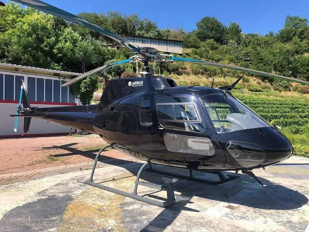
Free — save the 350 to your watchlist and track it in one place.
More EUROCOPTER AS350B-2manuals & documents
Related documents
- Rotorcraft Flight Manual Supplement for Inlet Barrier Filter System InstallationLEONARDO AW109SP GRANDNEW · Flight Manual Supplement
- INLET BARRIER FILTER SYSTEMEUROCOPTER AS350B3E · Maintenance Manual
- INLET BARRIER FILTER SYSTEMEUROCOPTER AS350B3E · Maintenance Manual
- Bell 407 IBF KIT ICABELL 407GX · Maintenance Manual
- Bell 206L1/C30, L-3, L-4 IBF Instructions for Continued AirworthinessBELL 206L-3 · Maintenance Manual
If you fly the EUROCOPTER AS350B-2, you may also be researching these.


In this document
General Information
The IBF STC kit includes a fairing, engine interface kit, and electrical kit, providing a means to monitor filter condition and allowing airflow bypass if the filter is restricted.
Limitations
The limitations from the basic flight manual remain applicable, with the addition that flight under falling snow is permitted.
Emergency/Malfunction Procedures
Procedures for addressing filter restriction include monitoring engine conditions and opening the bypass door if necessary.
Normal Procedures
Before flight, ensure the helicopter is free of snow, slush, or ice, and check the filter for standing water.
Performance
Basic performance data charts are applicable if engine health checks are satisfactory.
Summary written by AI from the source document. Check the original before relying on it. See which parts of Sprinkle are written by AI.
Safety notes
- Operation with missing quarter turn filter fasteners may result in engine damage.
- Avoid operation in a dirty or dusty environment with the filter bypass door open.
- Service the filter before the next flight if the IBF FILTER light illuminates during takeoff.
- Monitor engine conditions for indications of degradation or compressor stall.
- Ensure the filter, bypass door, and intake cowling are clear of snow, slush, or ice before each flight.
Summary written by AI from the source document. Check the original before relying on it. See which parts of Sprinkle are written by AI.
Full document text
Supplement No. AFS-AS350B-IBF-FMS 17891 Chesterfield Airport Road Chesterfield, MO 63005 FAA APPROVED ROTORCRAFT FLIGHT MANUAL SUPPLEMENT FOR EUROCOPTER FRANCE MODELS AS350B, AS350B1, AS350BA, AS350B2 and AS350B3 ROTORCRAFT FLIGHT MANUAL WITH THE INLET BARRIER FILTER SYSTEM INSTALLATION Aircraft S/N_____________ Aircraft Reg. No. _____________ This supplement must be attached to applicable FAA Approved Rotorcraft Flight Manual, when the rotorcraft is modified by the installation of the DCI Inlet Barrier Filter (IBF) System in accordance with STC No. SR02393CH. The information contained herein supplements or supersedes the basic manual only in those areas listed herein. For limitations, procedures, and performance information not contained in this supplement, consult the basic Rotorcraft Flight Manual. FAA Approved Manager, Southwest Flight Test Section, AIR-713 Federal Aviation Administration Ft. Worth, TX Approval Date: _________________ for Monica Merritt FEB 24 2022 Donaldson Company, Inc. RFM Supplement For Eurocopter 17891 Chesterfield Airport Road AS-350B, B1, BA, B2, & B3 Aircraft Chesterfield, MO 63005 AFS-AS350B-IBF-FMS Page 2 of 11 FAA Approval Date: _____________ Revision: F LOG OF REVISIONS Revision No. Revision Description Pages Effected FAA Approved: Date: IR Initial Release All Joseph Meiss 12 Mar. 2007 A Added paragraph to clarify limitations and ability to use sand filter charts 5 & 9 Joseph Meiss 26 Nov. 2007 B Added caution to Normal Procedures 7 Joseph Meiss 8 Sep 2008 C Changed Address and Logo All E.M. Ward 5 Aug 2011 D Changed Performance section to add Arriel 2D engine requirements 9 Joseph Meiss 20 Sep 2011 E Revised title page, replaced all instances of Aerospace Filtration Systems and AFS with Donaldson Company and DCI, changed justification in Section 2, revised Caution segment in Section 3, added dotted box to Caution segment in Section 4, added Before Flight When Helicopter Is Uncovered And Exposed To Rain segment to Section 4, changed Figure 2-1 to Figure 4-1, changed justification of Note in Section 5, revised AS350B3 with Arriel 2D Engines Only segment in Section 5, revised For All Aircraft segment in Section 5, revised Caution in Section 5 All Robert Klase 5 Mar 2020 F Added NORMAL PROCEDURES cont. title to page 8 and PERFORMANCE cont. title to page 10. Revised AS350B3 with Arriel 2D Engine Only segment in Section 5 to include VEMD Power Increase “H125 Power” (MOD EC07.5102). 8 - 10 NOTE FEB 24 2022 Donaldson Company, Inc. RFM Supplement For Eurocopter 17891 Chesterfield Airport Road AS-350B, B1, BA, B2, & B3 Aircraft Chesterfield, MO 63005 AFS-AS350B-IBF-FMS Page 3 of 11 FAA Approval Date: _____________ Revision: F Revised text from previous revision is indicated by a black vertical line in the right border. TABLE OF CONTENTS SECTION TITLE PAGE 1 General Information 4 2 Limitations 5 3 Emergency/Malfunction Procedures 6 4 Normal Procedures 7 5 Performance 9 6 Weight and Balance 11 FEB 24 2022 Donaldson Company, Inc. RFM Supplement For Eurocopter 17891 Chesterfield Airport Road AS-350B, B1, BA, B2, & B3 Aircraft Chesterfield, MO 63005 AFS-AS350B-IBF-FMS Page 4 of 11 FAA Approval Date: _____________ Revision: F The Inlet Barrier Filter (IBF) STC kit (112005-101) consists of a fairing, an engine interface kit and an electrical kit. The fairing consists of a composite and aluminum structure, a filter assembly, a bypass door, differential pressure switch, filter maintenance aid, and integral seals. The engine interface consists of an aluminum channel structure. There is also a cockpit indicator/switch, circuit breaker, installation hardware and wiring. The IBF system provides a means of monitoring the condition of the filter both in-flight and on the ground, and a bypass capability allowing inlet airflow to bypass the filter should the filter become restricted. In-flight, the differential pressure switch measures the drop in pressure across the filter, and triggers the cockpit indicator/ switch alerting the pilot any time the differential pressure across the filter reaches or exceeds a preset value. The electromechanically actuated bypass door permits unfiltered air to enter the engine inlet chamber, should the filter media become obstructed, and can be opened or closed as required. The bypass system employs a cockpit indicator/switch on the instrument panel. The bypass system also includes a three amp circuit breaker located in the overhead panel, installation hardware and wiring. The cockpit indicator/switch is used to energize the actuator by depressing the switch to open the bypass door and depressing again to close the bypass door. When the filter has enough dirt/debris that causes the differential pressure to reach or exceed a preset value, the FILTER segment of the indicator will illuminate. The cockpit indicator/switch may be pressed to open the bypass door. When the bypass is fully opened, the BYPASS segment of the indicator will illuminate, and the differential pressure will decrease causing the FILTER light to go out. On the ground, a Filter Maintenance Aid, mounted to the inner frame of the IBF, displays the maximum differential pressure across the filter reached during the last flight. It is accessible only on the ground, providing the pilot or mechanic the ability to visually gauge the current condition of the filter. Operation of the aircraft with the IBF system installed requires use of the same performance information and/or charts as required in the Rotorcraft Flight Manual (RFM) for all operations as defined in Section 5 of this supplement. Therefore no new performance charts are required for installation and operation of the IBF system. GENERAL INFORMATION Section 1 FEB 24 2022 Donaldson Company, Inc. RFM Supplement For Eurocopter
Show full textShow less
17891 Chesterfield Airport Road AS-350B, B1, BA, B2, & B3 Aircraft Chesterfield, MO 63005 AFS-AS350B-IBF-FMS Page 5 of 11 FAA Approval Date: _____________ Revision: F The limitations specified in the basic flight manual and in the flight manual supplements remain applicable and are completed or modified by the following: - Flight under falling snow is permitted. INSTRUMENT MARKINGS AND PLACARDS Placard is located near the 3 amp circuit breaker and the indicator/ switch The indicator/switch (shown illuminated) is to open/close the filter bypass and warn the pilot of filter restriction in the inlet. The switch is segmented with two lights. The FILTER segment will illuminate when the differential pressure is above a preset value. The BYPASS segment will illuminate whenever the bypass doors are open. LIMITATIONS Section 2 FEB 24 2022 Donaldson Company, Inc. RFM Supplement For Eurocopter 17891 Chesterfield Airport Road AS-350B, B1, BA, B2, & B3 Aircraft Chesterfield, MO 63005 AFS-AS350B-IBF-FMS Page 6 of 11 FAA Approval Date: _____________ Revision: F Caution Lights (amber) PANEL WORDING FAULT CONDITION CORRECTIVE ACTION IBF FILTER Illumination of IBF FILTER light indicates the preset value for the pressure differential has been reached. NOTE As the filter assembly becomes contaminated, certain flight conditions may cause the indicator to flicker intermittently. Corrective action should be taken only when the indicator illumination is continuous. Monitor engine conditions for any indications of engine degradation or compressor stall, i.e. T4 fluctuations, and decreasing or fluctuating Ng rpm. If rise in T4 or engine performance is unacceptable: Open bypass door by pressing illuminated FILTER indicator/switch. BYPASS segment of the indicator/switch should illuminate and the FILTER segment should turn off indicating the bypass door is open and the pressure differential is back within the normal range. Service filter prior to next flight. NOTE If IBF FILTER light illuminates during take- off, recommend servicing the filter before continuing flight. C To prevent compressor erosion, avoid operation in a dirty or dusty environment with the filter bypass door open. EMERGENCY/MALFUNCTION PROCEDURES Section 3 CAUTION FEB 24 2022 Donaldson Company, Inc. RFM Supplement For Eurocopter 17891 Chesterfield Airport Road AS-350B, B1, BA, B2, & B3 Aircraft Chesterfield, MO 63005 AFS-AS350B-IBF-FMS Page 7 of 11 FAA Approval Date: _____________ Revision: F FUSELAGE – CENTER 1. Ensure IBF environmental protective cover is removed. 2. Check IBF Filter Maintenance Aid to determine condition of the filters. When indicator enters RED zone (See Figure 2-1 of this FMS), it is recommended the filter be serviced IAW IBF Instructions for Continued Airworthiness, AFS-AS350B-IBF- ICA. 3. Perform a visual check to verify that the bypass doors are in the closed position. CAUTION Operation with missing quarter turn filter fasteners may result in damage to engine. Missing quarter turn fasteners should be replaced. BEFORE FLIGHT WHEN OPERATING IN SNOW CONDITIONS 1. Thoroughly check cabin roof, intake cowling, and filter areas. All areas checked shall be clean and free of accumulated snow, slush, and ice before each flight. 2. Ensure that the filter, by-pass door, and intake cowling are thoroughly clear of snow, slush, or ice before each flight. BEFORE FLIGHT WHEN HELICOPTER IS UNCOVERED AND EXPOSED TO RAIN 1. Check filter for standing water in between the pleats of the media. If standing water is observed, remove the filter, flip upside down, shake until water is removed and then reinstall filter. NORMAL PROCEDURES Section 4 CAUTION FEB 24 2022 Donaldson Company, Inc. RFM Supplement For Eurocopter 17891 Chesterfield Airport Road AS-350B, B1, BA, B2, & B3 Aircraft Chesterfield, MO 63005 AFS-AS350B-IBF-FMS Page 8 of 11 FAA Approval Date: _____________ Revision: F NORMAL PROCEDURES (cont.) Figure 4-1. FILTER MAINTENANCE AID – (ABOVE) “YELLOW Indicator” position relative to SAFE OPERATING ZONE (“GREEN Zone”) or SERVICE FILTER (“RED Zone”) markings defines current filter condition and pushing “YELLOW RESET Button” resets indicator. (BELOW) FMA unit is mounted to inner frame of IBF assembly and can be viewed through access window in the upper fairing. RED Zone GREEN Zone YELLOW Indicator GREEN Zone YELLOW RESET Button RED Zone YELLOW Indicator Press YELLOW Button to RESET FMA Viewing Window FEB 24 2022 Donaldson Company, Inc. RFM Supplement For Eurocopter 17891 Chesterfield Airport Road AS-350B, B1, BA, B2, & B3 Aircraft Chesterfield, MO 63005 AFS-AS350B-IBF-FMS Page 9 of 11 FAA Approval Date: _____________ Revision: F For All Aircraft Except AS350B3 with Arriel 2D Engine When the Inlet Barrier Filter (IBF) system STC is installed, use the basic inlet Engine Power Check (EPC) chart to determine engine health. If the EPC is satisfactory then basic performance can be obtained and the basic performance data charts are applicable. If the engine health check is not satisfactory then either clean the filter and recheck the engine health using the basic Engine Power Check chart or recheck the engine health using the Sand Filter Engine Power Check chart located in the Sand Filter supplement. If engine health is satisfactory Sand Filter performance can be obtained and the Sand Filter performance data charts are applicable. If the engine health is not satisfactory then either clean the filter or contact maintenance for troubleshooting. NOTE For aircraft equipped with Vehicle Engine Management Display (VEMD), the VEMD is programmed for a Basic Inlet. If engine health check is unsatisfactory for Basic Inlet EPC, Sand Filter Performance data (located in the Sand Filter Supplement) is required. The performance requirements must then be determined manually. For AS350B3 with Arriel 2D Engine Only – Including Aircraft with VEMD Power Increase “H125 Power” (MOD EC07.5102) When the Inlet Barrier Filter (IBF) system STC is installed, the VEMD is programmed for Basic Inlet. After performing an EPC, correct the results on VEMD: Add 3% on TRQ MARGIN / N1 displayed: Engine Health / N1 = TRQ MARGIN / N1 + 3 Remove 3% of TRQ MARGIN / TOT displayed: Engine Health / TOT = TRQ MARGIN / TOT - 3 If the Engine Health obtained are satisfactory (>=0), then: The engine health is ensured. The Hover basic performances are ensured and the basic Hover performance data charts are applicable. The Basic Rate of Climb performance is decreased. Remove 140 ft/mn to the Basic Rate of Climb performance charts result. If one of the Engine Health is not satisfactory (<0), then clean the filter and recheck the engine health following the above procedure. PERFORMANCE Section 5 FEB 24 2022 Donaldson Company, Inc. RFM Supplement For Eurocopter 17891 Chesterfield Airport Road AS-350B, B1, BA, B2, & B3 Aircraft Chesterfield, MO 63005 AFS-AS350B-IBF-FMS Page 10 of 11 FAA Approval Date: _____________ Revision: F PERFORMANCE (cont.) If the cleaning of the filter is not possible, and Engine Health is not satisfactory, then check the maintenance aid indicator: If indicator >= 6 then: - Add 4% on TRQ MARGIN / N1 displayed: Engine Health / N1 = TRQ MARGIN / N1 + 4 - No correction of TRQ MARGIN / TOT displayed: Engine Health / TOT = TRQ MARGIN / TOT If indicator >= 10 then: - Add 5% on TRQ MARGIN / N1 displayed: Engine Health / N1 = TRQ MARGIN / N1 + 5 - Add 2% on TRQ MARGIN / TOT displayed: Engine Health / TOT = TRQ MARGIN / TOT + 2 If the Engine Health is still not satisfactory then contact maintenance for troubleshooting. For All Aircraft The frequency at which the EPC is conducted is up to the discretion of the operator based on the operating environment, (i.e. temperature, altitude, airborne contaminate) and the requirements of the Flight Manual or applicable Flight Manual Supplement. Contact maintenance for appropriate trouble shooting procedures as outlined in applicable Instructions for Continued Airworthiness or Maintenance Manuals. Ensure that the IBF FILTER caution lights are not illuminated during performance of the EPC. C Helicopter performance is reduced as the IBF becomes contaminated with dirt, dust and debris. The pilot/operator is responsible to utilize the Engine Power Check (EPC) procedure to determine if the engine can produce installed power. If engine health check is not satisfactory, published performance cannot be achieved. C Helicopter performance is reduced as the IBF becomes contaminated with dirt, dust and debris. The pilot/operator is responsible to utilize the Engine Power Check (EPC) procedure to determine if the engine can produce installed power. If engine health check is not satisfactory, published performance cannot be achieved. CAUTION FEB 24 2022 Donaldson Company, Inc. RFM Supplement For Eurocopter 17891 Chesterfield Airport Road AS-350B, B1, BA, B2, & B3 Aircraft Chesterfield, MO 63005 AFS-AS350B-IBF-FMS Page 11 of 11 FAA Approval Date: _____________ Revision: F No Change WEIGHT AND BALANCE Section 6 FEB 24 2022