cessna-skycatcher-checklist.pdf - Empyrean Aero
CESSNA 210 · Checklist
Overview
The Cessna 162 Skycatcher Pilot's Operating Handbook (POH) provides essential information for pilots operating the Cessna 162 Skycatcher. This document includes detailed specifications, performance data, operating procedures, and safety information necessary for the safe and efficient operation of the aircraft. It serves as a comprehensive guide for both new and experienced pilots, ensuring they understand the aircraft's capabilities and limitations. The handbook covers various aspects of flight operations, including preflight checks, emergency procedures, and performance calculations, making it an indispensable resource for anyone flying the Skycatcher.
- Maximum takeoff weight: 1,320 lbs (600 kg)
- Stall speed in landing configuration: 45 knots
- Maximum cruise speed: 118 knots
- Rate of climb: 730 feet per minute
- Fuel capacity: 24 gallons (91 liters)
Document
Source
Originally published by empyreanaero.com. Sprinkle hosts a reference copy with an added summary, specifications and searchable full text.
Document details
- Type
- Checklist
- Year
- 2010
- Pages
- 36
- File size
- 8.7 MB
- Publisher
- empyreanaero.com
Common. Rarer than 1% of the aircraft models we track.
Most owners only have the POH. Here's the essential set for the CESSNA 210.
CESSNA 210 for sale now


Free — save the 210 to your watchlist and track it in one place.
More CESSNA 210manuals & documents
See all 28 →- Service Bulletin SB-14 - McFarlane AviationService Bulletins
- In-flight break-up involving Cessna 210N, VH-TFTOther Documents
- Fuel starvation involving Cessna T210M, VH-MYWOther Documents
- Engine failure and collision with terrain involving Cessna P210N ...Other Documents
- AIRWORTHINESS BULLETIN Cessna Single Engine Electro-Hydraulic Undercarriage Retraction SystemsService Bulletins
- Request for Legal Interpretation of 14 C.F.R. §§ 91.403(c) and 43.16 Concerning Whether Requirements in an Airworthiness Limitations Section (ALS) Developed By a Design Approval Holder (DAH) and Approved by the Federal Aviation Administration (FAA) as a Change to Type DesignMaintenance Manual
- Backdoor Rulemaking? | Savvy AviationMaintenance Manual
- ATSB Transport Safety ReportOther Documents
- SERVICE LETTER SEL-29-01 Revision 1: Hydraulic Power Pack InspectionWiring Diagram
- Airplane Upset Recovery Training Aid Revision 2Training Manual
- Airworthiness Directive AD/CESSNA 210/69 Amdt 2Airworthiness Directives
- SCHEDULE OF AIRWORTHINESS DIRECTIVESAirworthiness Directives
If you fly the CESSNA 210, you may also be researching these.


In this document
Aircraft Specifications
The Cessna 162 Skycatcher features a high-wing design with a maximum takeoff weight of 1,320 lbs (600 kg). It is powered by a Continental O-200 engine, producing 100 horsepower. The aircraft has a wingspan of 36 feet 2 inches (11.02 m) and a length of 24 feet 5 inches (7.44 m). The fuel capacity is 24 gallons (91 liters), providing a range of approximately 400 nautical miles under optimal conditions.
Performance Data
The Cessna 162 Skycatcher has a stall speed of 45 knots in landing configuration and a maximum cruise speed of 118 knots. The rate of climb is approximately 730 feet per minute at sea level. The aircraft requires a takeoff distance of about 1,200 feet over a 50-foot obstacle and a landing distance of around 1,000 feet.
Operating Procedures
Pilots must conduct a thorough preflight inspection, including checking fuel levels, control surfaces, and tire pressures. The engine start procedure involves ensuring the mixture is rich, the throttle is open 1/4 inch, and the ignition switch is in the 'both' position. During flight, pilots should monitor engine instruments and maintain appropriate airspeeds.
Emergency Procedures
In the event of an engine failure during takeoff, pilots should maintain control of the aircraft and attempt to land straight ahead. For in-flight engine failure, the recommended glide speed is 65 knots, and pilots should identify a suitable landing area.
Weight and Balance
Proper weight and balance calculations are critical for safe flight operations. The maximum baggage allowance is 120 lbs (54 kg), and pilots should ensure that the center of gravity remains within limits for all loading configurations.
Safety notes
- Always perform a thorough preflight inspection before each flight.
- Monitor engine instruments during flight to ensure proper operation.
- Adhere to weight and balance limits to maintain aircraft safety.
Full document text
Pilots' Checklist Cessna A Textron Company SKYCATCHER C NI620 Model 162 Serials 16200001 and On THIS CHECKLIST IS CURRENT WITH MODEL 162 POH (SERIALS 16200001 AND ON) U.S. PILOT'S OPERATING HANDBOOK, REVISION 4, DATED 21 OCTOBER, 2011. (PART NUMBER 162PHUS-04) COPYRIGHT © 2009 CESSNA AIRCRAFT COMPANY WICHITA, KANSAS, USA 162CLUS-04 ORIGINAL ISSUE 22 JULY 2009 REVISION 4 21 OCTOBER 2011 Model 162 Garmin G300 Pilot's Checklist NORMAL PROCEDURES TABLE OF CONTENTS Page Airspeeds For Normal Operation. N-2 PREFLIGHT INSPECTION. Cabin... N-3 N-4 Left Wing. N-6 Left Wing Leading Edge. N-8 Left Wing Trailing Edge N-8 Empennage. Right Wing Trailing Edge. N-9 N-9 C Right Wing. Nose N-10 N-12 Before Starting Engine.. N-15 Starting Engine (With Battery) N-16 Starting Engine (With External Power). N-18 Taxi Check.. N-21 Before Takeoff N-22 TAKEOFF N-24 Normal Takeoff. N-24 Short Field Takeoff. N-24 Enroute Climb N-25 Cruise N-25 Descent. N-25 Before Landing N-26 LANDING N-26 Normal Landing. N-26 Short Field Landing N-27 Balked Landing N-27 After Landing.. Securing Airplane N-28 N-28 162CLUS-04 N-1 NORMAL Pilot's Checklist Garmin G300 NOTICE Model 162 O O THE PILOT'S CHECKLIST SHOULD NOT BE USED UNTIL THE FLIGHT CREW HAS BECOME COMPLETELY FAMILIAR WITH THE AIRPLANE AND SYSTEMS. ALL NORMAL AND EMERGENCY PROCEDURE ITEMS AND COMPLETE PERFORMANCE IN THE PILOT'S OPERATING HANDBOOK AND FLIGHT TRAINING SUPPLEMENT SHALL TAKE PRECEDENCE IN CASE OF CONFLICT. REVISIONS Changes and/or additions to this checklist will be covered by Owner Advisory published by Cessna Aircraft Company. Owner Advisories are mailed automatically to owners of United States registered airplanes according to FAA records at the time of the issuance. Owner Advisories are mailed automatically to owners of other than United States registered airplanes, to the subscription address provided Cessna on an Owner Advisory Application. NOTE It is the responsibility of the owner to maintain this checklist in a current status when it is being used for operational purposes. Owners should contact a Cessna Service Station whenever the revision status of their checklist is in question. REVISED MATERIAL INDICATORS A bar will extend the full length of deleted, new or revised text added on new or previously existing pages. This bar will be located adjacent to the applicable text in the margin on the left side of the page. A bar in the footer will indicate a revision to the header/footer, a new page, format or spelling/grammar changes and/or that information has slipped to or from that page. A bar located adjacent to the figure number in the margin on the left side of the page will be used to indicate that the figure number only has changed. An asterisk located at the end of a figure number will be used to indicate that an illustration has been revised or is all new material (Ex: Figure 4*). All revised pages will carry the revision number opposite the page number on the applicable page. A list of revisions is located at the beginning of the Log of Effective Pages. O === 162CLUS-00 Model 162 Garmin G300 Pilot's Checklist Pilot's Checklist Garmin G300 Model 162 AIRSPEEDS NORMAL PROCEDURES PREFLIGHT INSPECTION B10717 (3) (+) 2 (5) 6 09101001 AIRSPEEDS FOR NORMAL OPERATION Unless otherwise noted, the following speeds are based on a maximum weight of 1320 pounds and may be used for any lesser weight. TAKEOFF Normal Climb Short Field Takeoff, Flaps 10°, Speed at 50 Feet ENROUTE CLIMB, FLAPS UP Normal, Sea Level. Best Rate of Climb Best Angle of Climb. LANDING APPROACH Normal Approach, Flaps UP. I Normal Approach, Flaps FULL. Short Field Approach, Flaps FULL BALKED LANDING Maximum Power, Flaps 25°. MAXIMUM RECOMMENDED PENETRATION SPEED 65-75 KIAS 55 KIAS 65-75 KIAS ...62 KIAS 57 KIAS 60-70 KIAS 55-60 KIAS 50 KIAS 50 KIAS TURBULENT AIR NOTE Visually check airplane for general condition during walk-around inspection. Airplane should be parked in a normal ground attitude (refer to Figure 1-1 in the POH) to make sure that fuel drain valves allow for accurate sampling. In cold weather, remove even small accumulations of frost, ice or snow from wing, tail and control surfaces. Also, make sure that control surfaces contain no internal accumulations of ice or debris. If a night flight is planned, check operation of all lights, and make sure a flashlight is available. Figure 1 1320 POUNDS. 1200 POUNDS 1100 POUNDS 89 KIAS .85 KIAS .80 KIAS MAXIMUM DEMONSTRATED CROSSWIND VELOCITY Takeoff or Landing.. .12 KNOTS MAXIMUM RECOMMENDED WIND VELOCITY All Operations. .22 KNOTS 162CLUS-00 N-3 N-2 162CLUS-04 11. MASTER Switch (ALT and BAT) Model 162 Garmin G300 PREFLIGHT INSPECTION (Continued) ① CABIN (Continued) 10. MAGNETOS Switch.. 12. AVN MASTER Switch Pilot's Checklist Pilot's Checklist Garmin G300 PREFLIGHT INSPECTION (Continued) Model 162 1 CABIN OFF ON 1. Pilot's Operating Handbook. 2. Garmin G300 Pilot's Guide AS DESIRED AS DESIRED ON 3. Pilot's Checklist.. ACCESSIBLE TO PILOT 13. Primary Flight Display (PFD). .CHECK 4. Parking Brake. I 15. PFD ADAHRS Test and MFD SELF TEST... I 16. LOW VOLTS Annunciator (verify PFD is ON and software current) 14. Multifunction Flight Display (MFD) (if installed) .......CHECK (verify MFD is ON) COMPLETE (verify no red X's shown) ....CHECK a. Brakes... .SET .APPLY 5. 6. b. PARKING BRAKE Control Knob . Secondary Interior Door Latch (if installed) BRS Activation Handle (if installed). a. Handle Mount . . . . . OON (pull full out) OPEN CHECK b. Safety Pin (verify annunciator is shown) c. Activation Cable 7. Control Stick Lock. NOTE 8. Wing Flaps 9. Fuel Quantity Indicators CHECK (security and condition) INSTALLED AND FLAG ATTACHED CHECK (security and condition) REMOVE UP CHECK (L and R) WARNING | LOW VOLTS Annunciator will only be shown if battery voltage is less than 12.5 volts. Verify battery voltage on PFD/MFD ENG page. 17. Elevator Trim Control. 18. Avionics Cooling Fan. 19. Airplane Weight and Balance.. 20. AVN MASTER Switch
Show full textShow less
21. MASTER Switch (ALT and BAT) 22. Fire Extinguisher (if installed).. T/O POSITION ....CHECK (verify fan is operational) .CHECKED and ENTERED GRND OFF OFF .CHECK (verify gage pointer in green arc) 23. BRS Softpack (if installed)....CHECK (security and condition) (refer to POH/FTS, Section 9, Supplement 5 for more information on the optional BRS installation) TAKEOFF IS PROHIBITED WITH LESS THAN 14 TANK OF FUEL. MIN T.O. MARKING ON FUEL INDICATOR WHEN THE MASTER SWITCH IS ON, USING AN EXTERNAL POWER SOURCE, OR MANUALLY ROTATING THE PROPELLER, TREAT THE PROPELLER AS IF THE MAGNETOS SWITCH WERE ON. DO NOT STAND, NOR ALLOW ANYONE ELSE TO STAND, WITHIN THE ARC OF THE PROPELLER SINCE A LOOSE OR BROKEN WIRE, OR A COMPONENT MALFUNCTION, COULD CAUSE THE ENGINE TO START. 162CLUS-04 (Continued Next Page) N-5 N-4 (Continued Next Page) 162CLUS-04 Model 162 Garmin G300 PREFLIGHT INSPECTION (Continued) LEFT WING (Continued) 8. Fuel Tank Sump Quick Drain Valves Pilot's Checklist Pilot's Checklist DRAIN Garmin G300 PREFLIGHT INSPECTION (Continued) ②LEFT WING 1. Cabin Door . . Drain at least a cupful of fuel (using sampler cup) from each sump location to check for water, sediment, and proper fuel grade before each flight and after each refueling. If water is observed, take further samples until clear and then gently rock wings and lower tail to the ground to move any additional contaminants to the sampling points. Take repeated samples from all fuel drain points until all contamination has been removed. If contaminants are still present, refer to WARNING below and do not fly airplane. NOTE Collect all sampled fuel in a safe container. Dispose of the sampled fuel so that it does not cause a nuisance, hazard, or damage to the environment. WARNING IF, AFTER REPEATED SAMPLING, EVIDENCE OF CONTAMINATION STILL EXISTS, THE AIRPLANE SHOULD NOT BE FLOWN. TANKS SHOULD BE DRAINED AND SYSTEM PURGED BY QUALIFIED MAINTENANCE PERSONNEL. ALL EVIDENCE OF CONTAMINATION MUST BE REMOVED BEFORE FURTHER FLIGHT. 162CLUS-04 (Continued Next Page) Model 162 CHECK (security and condition) CHECK 2. Main Wheel Tire (proper inflation and general condition (weather checks, tread depth and wear, etc.)) 3. Brake Line. I 4. Wheel Fairings (if installed). CHECK (security and condition) CHECK (security and condition) 5. Fresh Air Vent. 6. Fuel Quantity.. ... CHECK (blockage) CHECK VISUALLY (for desired level) N-7 IN-6 WARNING TAKEOFF IS PROHIBITED WITH LESS THAN 4 TANK OF FUEL. GRND MIN T.O. MARKING ON FUEL INDICATOR 7. Fuel Filler Cap.. .SECURE and VENT CLEAR (Continued Next Page) 162CLUS-04 O Model 162 Garmin G300 PREFLIGHT INSPECTION (Continued) Pilot's Checklist Pilot's Checklist Garmin G300 PREFLIGHT INSPECTION (Continued) Model 162 ⑤EMPENNAGE ③LEFT WING Leading Edge 1. Rudder Gust Lock (if installed). 2. Control Surfaces REMOVE ....CHECK 1. Fuel Tank Vent Opening CHECK (blockage) (freedom of movement and security) 2. Wing Tiedown. DISCONNECT 3. Elevator Trim Tab. .... CHECK (security) (verify tab is faired with elevator and trim indicator in T/O position) 3. Pitot Tube Cover. 4. Tail Tiedown.. DISCONNECT 4. Landing Light.. (check security and condition) .REMOVE (check for pitot blockage) CHECK ⑥RIGHT WING Trailing Edge 5. Strobe/Nav Light . . . 1. ELT and GPS Antennas.... .CHECK 2. 3. (security of attachment and general condition) Flap Gust Lock (if installed) Flap (condition, operation and cleanliness of cover) CHECK (condition, operation and cleanliness of cover) I 4. Aileron REMOVE DEFLECT and CHECK (flap/aileron cables, up-spring tension and general condition) ....CHECK (freedom of movement and security) LEFT WING Trailing Edge O 1. Aileron.. CHECK NOTE Check for proper aileron movement by pushing the aileron up from the neutral (or faired with the flaps in the Flaps UP position and returning the aileron back to the neutral or faired position. Pushing down on the aileron may create an over-centered condition requiring re- centering of the cockpit control stick. 162CLUS-04 (Continued Next Page) (freedom of movement and security) NOTE Check for proper aileron movement by pushing the aileron up from the neutral (or faired with the flaps in the Flaps UP position) and returning the aileron back to the neutral or faired position. Pushing down on the aileron may create an over-centered condition requiring re- centering of the cockpit control stick. I 2. 3. Flap Gust Lock (if installed). Flap.... I 4. 5. .REMOVE DEFLECT and CHECK (flap/aileron cables, up-spring tension and general condition) Com Antenna and OAT Temp Probe. ... CHECK (security of attachment and general condition) BRS Parachute Harness Covers (if installed) . . . . . . . . CHECK (security of attachment and general condition) (Continued Next Page) N-9 IN-8 162CLUS-04 Model 162 Garmin G300 Pilot's Checklist Pilot's Checklist RIGHT WING (Continued) Garmin G300 PREFLIGHT INSPECTION (Continued) Model 162 O C 8. Wheel Fairings (if installed). 9. ..CHECK (security and condition) DRAIN Fuel Tank Sump Quick Drain Valves Drain at least a cupful of fuel (using sampler cup) from each sump location to check for water, sediment, and proper fuel grade before each flight and after each refueling. If water is observed, take further samples until clear and then gently rock wings and lower tail to the ground to move any additional contaminants to the sampling points. Take repeated samples from all fuel drain points until all contamination has been removed. If contaminants are still present, refer to WARNING below and do not fly airplane. NOTE Collect all sampled fuel in a safe container. Dispose of the sampled fuel so that it does not cause a nuisance, hazard or damage to the environment. WARNING IF, AFTER REPEATED SAMPLING, EVIDENCE OF CONTAMINATION STILL EXISTS, THE AIRPLANE SHOULD NOT BE FLOWN. TANKS SHOULD BE DRAINED AND SYSTEM PURGED BY QUALIFIED MAINTENANCE PERSONNEL. ALL EVIDENCE OF CONTAMINATION MUST BE REMOVED BEFORE FURTHER FLIGHT. 10. Cabin Door. ..CHECK (security, condition and make sure door is unlocked prior to flight) RIGHT WING 1. Strobe/Nav Light.. . CHECK 2. Wing Tiedown 3. Low Airspeed Alert and Stall Warning Opening....... CHECK (blockage) (condition, operation and cleanliness of cover) DISCONNECT (check security and condition) NOTE To check the system, place a clean handkerchief over the vent opening and apply suction; a sound from the warning horn will confirm system operation. 4. Fuel Quantity.. CHECK VISUALLY (for desired level) WARNING TAKEOFF IS PROHIBITED WITH LESS THAN 14 TANK OF FUEL. GRND MIN T.O. MARKING ON FUEL INDICATOR 5. Fuel Filler Cap... 6. Main Wheel Tire .SECURE and VENT CLEAR CHECK WARNING CABIN DOOR(S) CANNOT BE UNLOCKED FROM INSIDE THE AIRPLANE. 11. Fresh Air Vent ..CHECK (blockage) (Continued Next Page) 162CLUS-04 (proper inflation and general condition (weather checks, tread depth and wear, etc.)) 7. Brake Line. . . CHECK (security and condition) N-11 N-10 (Continued Next Page) 162CLUS-04 Model 162 Garmin G300 PREFLIGHT INSPECTION (Continued) Ⓡ NOSE (Continued) 8. Fuel Strainer Quick Drain Valve . . Pilot's Checklist Pilot's Checklist DRAIN (bottom left side of engine cowling) Drain at least a cupful of fuel (using sampler cup) from valve to check for water, sediment, and proper fuel grade before each flight and after each refueling. If water is observed, take further samples until clear and then gently rock wings and lower tail to the ground to move any additional contaminants to the sampling points. Take repeated samples from all fuel drain points, including the fuel strainer and fuel sump valve, until all contamination has been removed. If contaminants are still present, refer to WARNING below and do not fly the airplane. NOTE Collect all sampled fuel in a safe container. Dispose of the sampled fuel so that it does not cause a nuisance, hazard, or damage to the environment. WARNING IF, AFTER REPEATED SAMPLING, EVIDENCE OF CONTAMINATION STILL EXISTS, THE AIRPLANE SHOULD NOT BE FLOWN. TANKS SHOULD BE DRAINED AND SYSTEM PURGED BY QUALIFIED MAINTENANCE PERSONNEL. ALL EVIDENCE OF CONTAMINATION MUST BE REMOVED BEFORE FURTHER FLIGHT. Garmin G300 PREFLIGHT INSPECTION (Continued) ⑧ NOSE Model 162 1. Engine Cooling Air Inlets.. . CHECK 2. Propeller and Spinner 3. Air Filter.... (clear of obstructions) CHECK (for nicks and security) CHECK 4. 5. (for condition and blockage by dust or other foreign matter) Nosewheel Strut and Tire ... CHECK (strut and general condition of tire (weather checks, tread depth and wear, etc.)) Nosewheel Fairing (if installed). 6. Engine Exhaust Outlet 7. Engine Oil Dipstick/Filler Cap: a. Oil level.... b. Dipstick/filler cap. NOTE CHECK (security and condition) CHECK (security and condition) CHECK SECURE (lever horizontal and facing aft) Do not operate with less than 3.5 quarts. Fill to 5 quarts for extended flight. 162CLUS-04 (Continued Next Page) N-13 IN-12 (Continued Next Page) 162CLUS-04 C Garmin G300 Pilot's Checklist Pilot's Checklist Model 162 BEFORE STARTING ENGINE 1. Preflight Inspection Passenger Briefing.. Rudder Pedals. 2. 3. 4. Seat Belts. 5. Cabin Doors. 6. Brakes 7. Circuit Breakers. 8. Electrical Equipment 9. AVN MASTER Switch CAUTION COMPLETE COMPLETE . ADJUST ADJUST and SECURE AS DESIRED TEST and SET CHECK IN OFF THE AVIONICS MASTER SWITCH MUST BE OFF DURING ENGINE START TO PREVENT POSSIBLE DAMAGE TO AVIONICS. 10. FUEL SHUTOFF Valve OFF ON (push full in) Garmin G300 PREFLIGHT INSPECTION (Continued) NOSE (Continued) 9. Fuselage Fuel Sump Quick Drain Valve ... Model 162 .DRAIN (bottom center rear of engine cowling) Drain at least a cupful of fuel (using sampler cup) from valve to check for water, sediment, and proper fuel grade before each flight and after each refueling. If water is observed, take further samples until clear and then gently rock wings and lower tail to the ground to move any additional contaminants to the sampling points. Take repeated samples from all fuel drain points, including the fuel strainer and fuel sump valve, until all contamination has been removed. If contaminants are still present, refer to WARNING below and do not fly the airplane. NOTE Collect all sampled fuel in a safe container. Dispose of the sampled fuel so that it does not cause a nuisance, hazard, or damage to the environment. WARNING IF, AFTER REPEATED SAMPLING, EVIDENCE OF CONTAMINATION STILL EXISTS, THE AIRPLANE SHOULD NOT BE FLOWN. TANKS SHOULD BE DRAINED AND SYSTEM PURGED BY QUALIFIED MAINTENANCE PERSONNEL. ALL EVIDENCE OF CONTAMINATION MUST BE REMOVED BEFORE FURTHER FLIGHT. 10. Static Source Opening (left side of fuselage). . . . . . . . . CHECK (verify opening is clear) 162CLUS-04 N-15 IN-14 162CLUS-04 O C Model 162 Garmin G300 Pilot's Checklist Pilot's Checklist Garmin G300 Model 162 THROTTLE Control . I STARTING ENGINE (With Battery) (Continued) IF FUEL PRIMER CONTROL NOT INSTALLED IF ENGINE COLD 9. 10. THROTTLE Control IF ENGINE WARM 9. THROTTLE Control. STARTING ENGINE (With Battery) 1. AVN MASTER Switch .CHECK (verify off) 2. MASTER Switch (ALT and BAT). .ON 3. CARB HEAT Control Knob .OFF PUMP (3 to 6 strokes) (push full in) OPEN 1/4 INCH 4. MIXTURE Control FULL RICH PUMP ONCE 10. THROTTLE Control.. (push full in and pull full out) CLOSED I I 11. Propeller Area CLEAR (verify that all people and equipment are at a safe distance from the propeller) 12. MAGNETOS Switch.. (push full in) CHECK PARAMETERS (verify no red X's through indicators) CHECK EIS ENGINE PAGE NOTE A red LOW VOLTS annunciator will come on when battery voltage is less than 12.5 volts. As battery voltage decreases, the Garmin G300 display will become less bright and eventually unreadable. If the starter fails to crank the engine or the G300 display becomes unreadable, service battery or apply external power. START (release when engine starts) NOTE I (verify discharge shown (negative)) 8. STROBE Light Switch.. ..ON 7. AMPS. CHECK о 5. Engine Indicating System. 6. VOLTS... If the engine is primed too much (flooded), place the mixture control in the IDLE CUTOFF position, open the throttle control 1/2 to full, and engage the starter motor (START). When the engine starts, advance the mixture control to the FULL RICH position and promptly retard the throttle control. 13. Oil Pressure . . . . .CHECK (verify that oil pressure increases above 10 PSI into the YELLOW BAND range in 30 seconds) 14. THROTTLE Control. 15. AMPS.. #Goo to IF FUEL PRIMER CONTROL INSTALLED IF ENGINE COLD 9. FUEL PRIMER Control .... 10. THROTTLE Control.. PUMP (1 to 3 strokes) OPEN 1/4 INCH 16. NAV Light Switch. REDUCE TO IDLE ...CHECK IF ENGINE WARM (verify charge shown (positive)) 9. FUEL PRIMER Control. ON 10. THROTTLE Control (as required) OFF ON LEAN (as required) (Continued Next Page) 17. STROBE Light Switch 18. AVN MASTER Switch 19. MIXTURE Control 162CLUS-04 GO TO PG N21 N-17 N-16 NONE CLOSED 162CLUS-04 C Model 162 Garmin G300 Pilot's Checklist STARTING ENGINE (With External Power) (if installed) (Continued) IF FUEL PRIMER CONTROL INSTALLED IF ENGINE COLD 14. FUEL PRIMER Control 15. THROTTLE Control. IF ENGINE WARM 14. FUEL PRIMER Control 15. THROTTLE Control. Pilot's Checklist Garmin G300 Model 162 STARTING ENGINE (With External Power) (if installed) 1. AVN MASTER Switch 2. 3. MASTER Switch (ALT and BAT). VOLTS..... .CHECK (verify off) ...ON CHECK EIS ENGINE PAGE PUMP (1 to 3 strokes) OPEN 1/4 INCH NOTE .NONE CLOSED A red LOW VOLTS annunciator will come on when battery voltage is less than 12.5 volts. As battery voltage decreases, the Garmin G300 display will become less bright and eventually unreadable. If the starter fails to crank the engine or the G300 display becomes unreadable, service battery or apply external power. 4. AMPS CHECK (verify discharge shown (negative)) MASTER Switch (ALT and BAT).. EXTERNAL POWER. | IF FUEL PRIMER CONTROL NOT INSTALLED IF ENGINE COLD 14. THROTTLE Control. 15. THROTTLE Control. IF ENGINE WARM 14. THROTTLE Control. I PUMP (3 to 6 strokes) 5. 6. OPEN 1/4 INCH ...OFF CONNECT (to external power receptacle) 7. MASTER Switch (ALT and BAT). ..ON 8. PUMP ONCE CARB HEAT Control Knob . OFF (push full in and pull full out) (push full in) I 15. THROTTLE Control. 9. CLOSED MIXTURE Control.. FULL RICH I 16. Propeller Area CLEAR 10. Engine Indicating System ... (verify that all people and equipment are at a safe distance from the propeller) I 11. VOLTS. (verify 12.5 to 15.0 volts annunciation is not shown) (push full in) CHECK PARAMETERS (verify no red X's through indicators) CHECK EIS ENGINE PAGE indication and LOW VOLTS I 12. AMPS. CHECK (Continued Next Page) I 13. STROBE Light Switch. (verify charge shown (positive)) ..ON 162CLUS-04 N-19 IN-18 (Continued Next Page) 162CLUS-04 C C Model 162 Garmin G300 Pilot's Checklist STARTING ENGINE (With External Power) (if installed) (Continued) I 25. Internal Power a. MASTER Switch (ALT). b. LDG Light Switch.. c. NAV Light Switch d. THROTTLE Control. Pilot's Checklist Garmin G300 Model 162 STARTING ENGINE (With External Power) (if installed) (Continued) CHECK 17. MAGNETOS Switch OFF ON ON REDUCE TO IDLE ON .INCREASE (to approximately 1500 RPM) ..CHECK (verify charge shown (positive)) WARNING e. MASTER Switch (ALT). f. THROTTLE Control. g. AMPS. .START (release when engine starts) NOTE If the engine is primed too much (flooded), place the mixture control in the IDLE CUTOFF position, open the throttle control 1/2 to full, and engage the starter motor (START). When the engine starts, advance the mixture control to the FULL RICH position and promptly retard the throttle control. 18. Oil Pressure CHECK (verify that oil pressure increases above 10 PSI into the YELLOW BAND range in 30 seconds) IF AMMETER DOES NOT SHOW POSITIVE CHARGE (+AMPS), REMOVE BATTERY FROM AIRPLANE AND SERVICE OR REPLACE BATTERY BEFORE FLIGHT. I 26. LDG Light Switch. 27. STROBE Light Switch 28. AVN MASTER Switch 29. THROTTLE Control. 30. MIXTURE Control TAXI CHECK 19. THROTTLE Control. 20. EXTERNAL POWER.. CAUTION REDUCE TO IDLE DISCONNECT OFF (as required) OFF ON REDUCE TO IDLE HAVE GROUND ATTENDANT DISCONNECT GROUND POWER CABLE AND LATCH EXTERNAL POWER RECEPTACLE DOOR. 21. Power... INCREASE (to approximately 1500 RPM for several minutes to charge LEAN battery) (as required) I 22. AMPS. CHECK I 23. VOLTS.. .CHECK (verify proper operation) 24. LOW VOLTS Annunciator. (verify charge shown (positive)) CHECK EIS ENGINE PAGE (verify 12.5 VOLTS minimum shown) ... CHECK (verify annunciator is not shown) 1. Brakes 2. Flight Instruments ..CHECK (verify proper indication while taxing) 162CLUS-04 N-21 N-20 (Continued Next Page) 162CLUS-04 Model 162 Garmin G300 Pilot's Checklist BEFORE TAKEOFF (Continued) 13. THROTTLE Control ... 1700 RPM (once oil temperature is above 75°F and oil pressure in green band range) a. MAGNETOS Switch.... .CHECK (RPM drop should not exceed 150 RPM on either magneto or 50 RPM differential between magnetos) b. Engine Indicators.. BEFORE TAKEOFF 3. 2. Rudder Pedals and Seat Belts Cabin Doors ...... .CHECK a. Primary Interior Door Latches Pilot's Checklist BEFORE TAKEOFF 1. Parking Brake. a. Brakes.. Garmin G300 Model 162 b. PARKING BRAKE Control Knob . SET .APPLY ..ON (pull full out) ADJUST and SECURE CHECK LATCHED C. CARB HEAT Control Knob. ON (1) Engine RPM. (pull full out) ....CHECK 4. Flight Controls. .... 5. Flight Instruments (PFD). (2) CARB °F. (verify RPM decreases) ....CHECK 6. Engine Indicating System .... (verify temp increases) b. Secondary Interior Door Latches (if installed) ... LATCHED FREE and CORRECT CHECK (verify no red X's through indicators) CHECK PARAMETERS (verify no red X's through indicators) d. CARB HEAT Control Knob. OFF O 7. Altimeter (push full in) 8. Fuel Quantity Indicators e. AMPS and VOLTS. ..CHECK SET CHECK (verify level is correct) ..CHECK 14. Annunciators 15. THROTTLE Control. 16. THROTTLE Control Friction Lock 17. COM Frequency. (verify no annunciators are shown) CHECK IDLE (800 RPM or LESS) ... ADJUST SET WARNING TAKEOFF IS PROHIBITED WITH LESS THAN 14 TANK OF FUEL. MIN C 18. GPS Flight Plan AS DESIRED GRND MARKING ON FUEL INDICATOR 19. Transponder. SET T.O. 20. Wing Flaps. UP-10° 9. (10° recommended) FUEL PRIMER Control Knob (if installed). IN and LOCKED 10. MIXTURE Control.. RICH C 21. NAV Light Switch ON 22. STROBE Light Switch ON 11. Autopilot (if installed). CHECK 23. BRS Activation Handle Safety Pin (if installed)..REMOVE and STOW (refer to POH/FTS, Section 9, Supplement 8 for operating procedures and system information) 12. Elevator Trim Control Switch.. SET FOR T/O (stow in door panel with zipper closed or pedestal side pocket for security and easy access after landing) 24. PARKING BRAKE Control Knob OFF (push full in) 162CLUS-04 N-23 N-22 (Continued Next Page) 162CLUS-04 Model 162 ENROUTE CLIMB Garmin G300 Pilot's Checklist Pilot's Checklist Garmin G300 Model 162 O TAKEOFF 1. Airspeed.. 65 - 75 KIAS NORMAL TAKEOFF 3. MIXTURE Control 2. THROTTLE Control. (above 3000 feet pressure altitude, lean for maximum RPM) FULL (push full in) 1. Wing Flaps .UP -10° RICH (10° recommended) 2. CARB HEAT Control Knob ..OFF (push full in) NOTE 3. THROTTLE Control. FULL 2. Elevator Trim Control Switch C For maximum performance climb speeds, refer to POH/ FTS, Section 5, Figure 5-6, Maximum Rate of Climb at 1320 Pounds. CRUISE 1. Power. (push full in) 4. MIXTURE Control. RICH 5. Directional Control.... 2400 2750 RPM (75% recommended) 6. Elevator Control (above 3000 feet pressure altitude, lean for maximum RPM) (use differential braking until rudder control becomes effective) LIFT NOSEWHEEL AT 50 KIAS MAINTAIN 7. Climb Airspeed ADJUST 8. Wing Flaps 3. MIXTURE Control LEAN 65-75 KIAS RETRACT (at safe altitude) (for best power setting) SHORT FIELD TAKEOFF DESCENT 1. Wing Flaps .10° 2. CARB HEAT Control Knob OFF 1. Power. AS DESIRED (push full in) 2. MIXTURE Control (2750 RPM maximum) .. ADJUST (if necessary to make engine run smoothly) 3. Brakes.. 4. THROTTLE Control. .APPLY FULL (push full in) 3. Altimeter. SET 5. MIXTURE Control .. RICH 4. Wing Flaps.. AS DESIRED (above 3000 feet pressure altitude, lean for maximum RPM) (UP 10° below 100 KIAS) (10° 25° below 85 KIAS) (25° FULL below 70 KIAS) 6. Brakes... 7. Elevator Control 8. Directional Control. RELEASE SLIGHTLY TAIL LOW .MAINTAIN 5. CARB HEAT Control Knob. ON (as required) 9. 10. Wing Flaps (use differential braking until rudder control becomes effective) Climb Airspeed .55 KIAS (until all obstacles are cleared) RETRACT SLOWLY (when airspeed is more than 60 KIAS) 162CLUS-04 N-25 N-24 162CLUS-04 Garmin G300 Pilot's Checklist Pilot's Checklist Model 162 SHORT FIELD LANDING 1. Airspeed.. BEFORE LANDING Garmin G300 Model 162 C 2. Wing Flaps. 3. Airspeed. NOTE 60-70 KIAS (Flaps UP) FULL 50 KIAS (until flare) The Low Airspeed Alert and Stall Warning System horn will sound during short field landing approach to alert pilot of the low airspeed condition. Pilot should monitor airspeed closely and be prepared to initiate stall avoidance procedures. 4. Elevator Trim Control. 5. Power. 6. Touchdown. 7. Brakes. 8. Wing Flaps. C ADJUST REDUCE TO IDLE (as obstacle is cleared) MAIN WHEELS FIRST APPLY HEAVILY (while maintaining directional control) LANDING 2. 1. Rudder Pedals and Seat Belts MIXTURE Control... ADJUST and SECURE RICH (push full in) C (below 3000 feet pressure altitude) 3. CARB HEAT Control Knob OON (pull full out) (apply full heat before reducing power) 4. LDG Light Switch.. .ON .OFF 5. Autopilot (if installed). LANDING NORMAL LANDING 1. Airspeed 2. Wing Flaps UP 3. Airspeed 60-70 KIAS (Flaps UP) AS DESIRED (UP 10° below 100 KIAS) (10° 25° below 85 KIAS) (25° FULL below 70 KIAS) 55-60 KIAS (Flaps FULL) - O BALKED LANDING 1. THROTTLE Control. 2. CARB HEAT Control Knob... 3. Wing Flaps. 4. Climb Speed. 5. Climb Speed.. 6. Wing Flaps. FULL (push full in) OFF (push full in) RETRACT to 25° 50 KIAS (until obstacle is cleared) . . . . 60 KIAS (after obstacle is cleared) 10°, then UP (after reaching a safe altitude and 60 KIAS) NOTE The Low Airspeed Alert and Stall Warning System horn may sound as the airplanes slows for landing flair and touchdown. Pilot should monitor airspeed closely and be prepared to initiate stall avoidance procedures. 4. Elevator Trim Control Switch. Touchdown 5. 6. Landing Roll 7. Braking. 8. Directional Control. ADJUST MAIN WHEELS FIRST LOWER NOSEWHEEL GENTLY MINIMUM REQUIRED MAINTAIN (with rudder and differential braking) 162CLUS-04 N-27 N-26 162CLUS-04
What's in the CESSNA 210 TCDS
A Type Certificate Data Sheet (TCDS) is the FAA's record of what an aircraft type was approved as. It is the source of truth for weights, seating, fuel and the rules the design was certified against. Expand any line to see what it means.
5,519 CESSNA 210 parts for sale
See all →

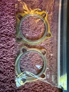
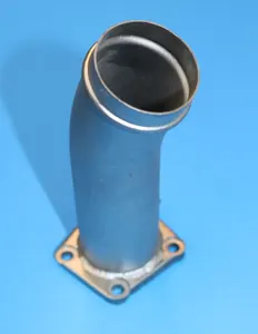
Parts listed for sale by vetted eBay sellers — confirmed on eBay at checkout.