ABI 180/185 Tail Gear Assembly Installation and ICA Manual
CESSNA A185E SKYWAGON · Maintenance Manual
Overview
This document provides installation instructions and continued airworthiness guidelines for the ABI 180/185 Tail Gear Assembly on Cessna Series 180 and 185 aircraft. It is intended for qualified maintenance personnel responsible for the installation and maintenance of the tail gear assembly.
- Applicable to Cessna 180 and 185 series aircraft.
- Includes installation and maintenance procedures for the ABI Tail Gear Assembly.
- Provides a parts list for the tail gear assembly.
- Details inspection and repair procedures for continued airworthiness.
- Weight of the installed ABI tail gear assembly is 11.13 lbs.
- Caution to lubricate the tail spring before installation.
- No airworthiness limitations associated with this modification.
- Manual should be retained for future reference.
Summary written by AI from the source document. Check the original before relying on it. See which parts of Sprinkle are written by AI.
Reference only, not for flight. Use the current approved manual for your aircraft. See terms, section 5.
Document
Source
Copy found at mcfarlaneaviation.com. Sprinkle hosts a reference copy with an added summary, specifications and searchable full text.
Document details
- Type ·
- Maintenance Manual
- Year ·
- 2014
- File size ·
- 478 KB
- Copy found at ·
- mcfarlaneaviation.com
- Language ·
- en
Specifications & performance
Extracted from this document.
Specifications
- Installed weight (lb) ·
- 11.13
What is the ABI 180/185 Tail Gear Assembly Installation and ICA Manual?
The ABI 180/185 Tail Gear Assembly Installation and ICA Manual is a maintenance manual for the CESSNA A185E SKYWAGON, dated 2014.
What year was the ABI 180/185 Tail Gear Assembly Installation and ICA Manual published?
The ABI 180/185 Tail Gear Assembly Installation and ICA Manual — the CESSNA A185E SKYWAGON maintenance manual on file — is dated 2014.
Common. More common than 99% of the aircraft models we track.
Most owners only have the POH. Here's the essential set for the CESSNA A185E SKYWAGON.
- Pilot's Operating Handbook / AFM
- Checklist
- Maintenance Manual
- Parts Catalog (IPC)
- Systems & Wiring
- Service Bulletins on file
- Type Certificate (TCDS)
CESSNA A185E SKYWAGON for sale now
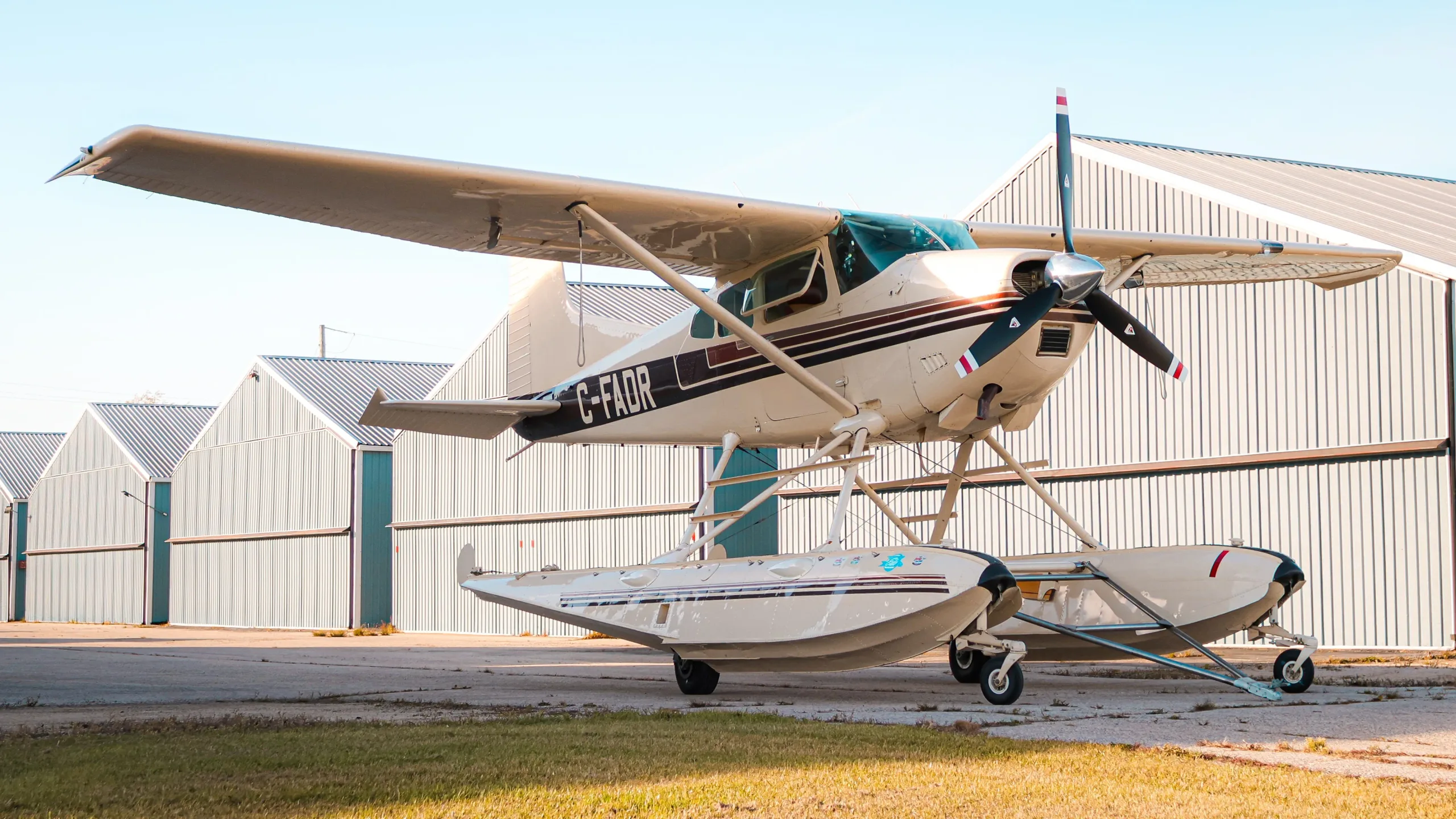
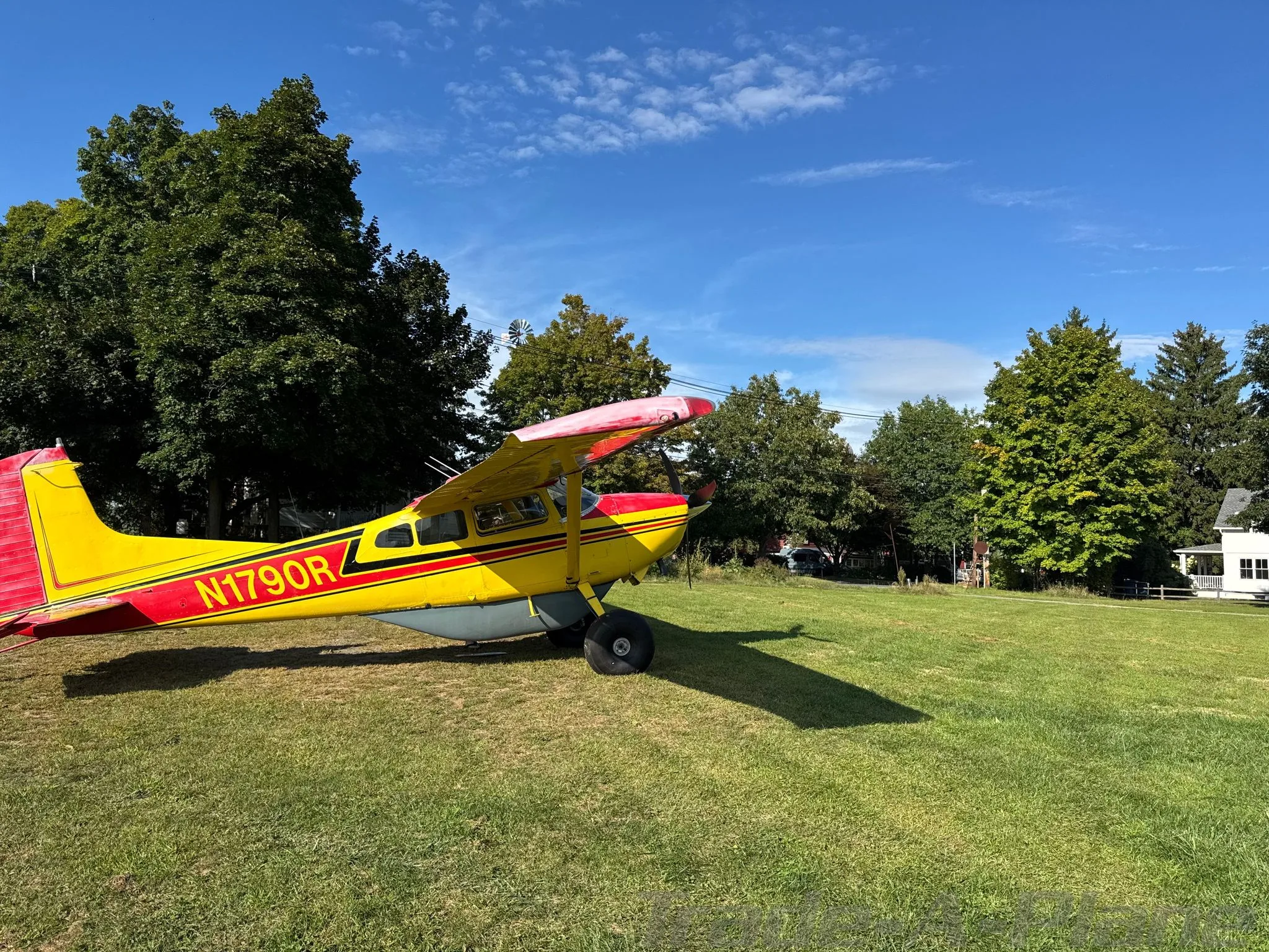
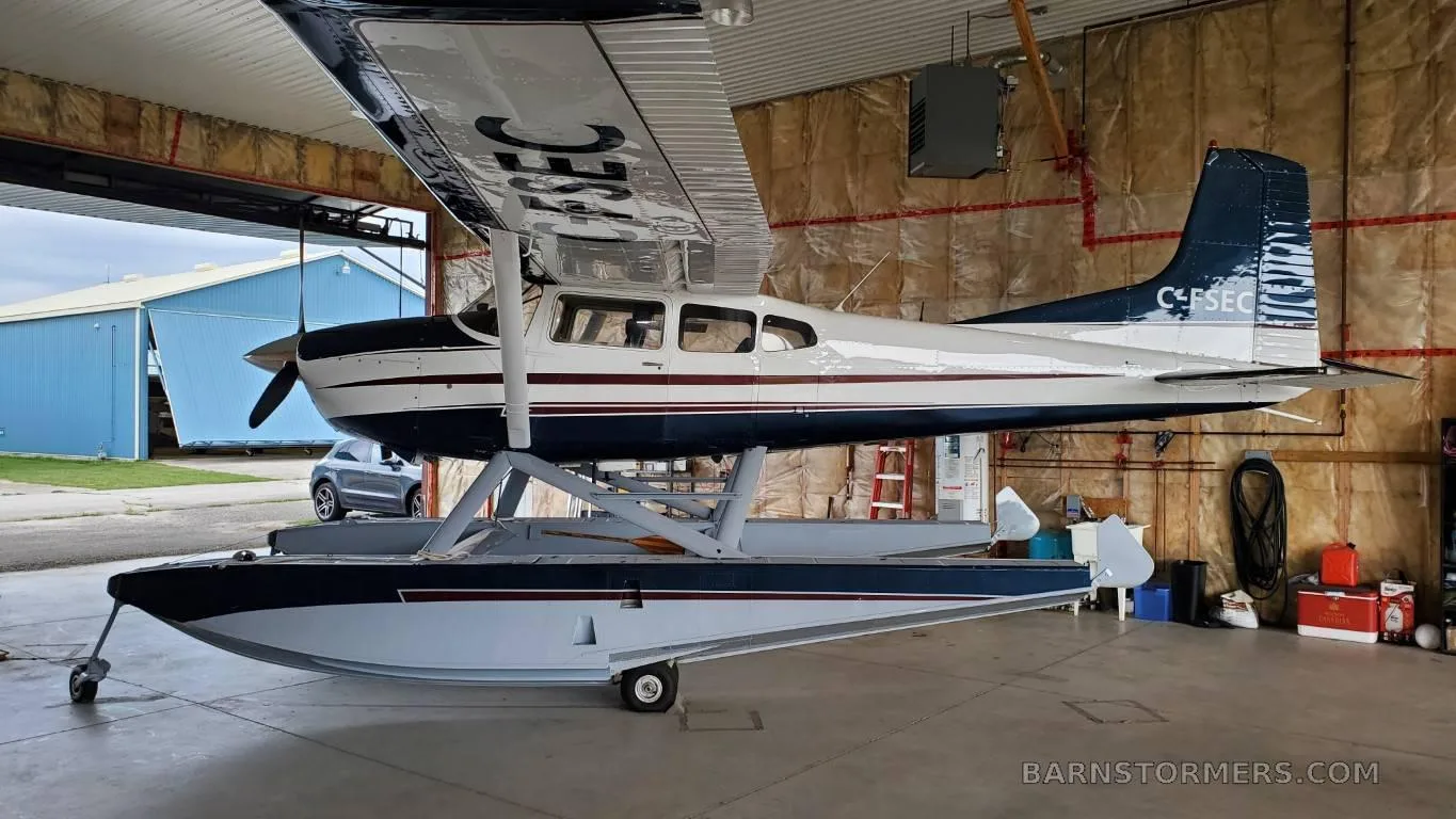
Free — save the 185 to your watchlist and track it in one place.
Related documents
- mr. thomas anderson - McFarlane AviationCESSNA 185 · Service Manual
- Cessna 170 & C305A (USAF O‐1A) T3 Tailwheel Suspension System Installation InstructionsCESSNA 170B · Weight & Balance
- Aero Twin, Inc. Rudder Gust Lock Kit No. AT-RL-1001CESSNA CARAVAN 208 FLOATPLANE · Parts Catalog
- SERVICE BULLETIN No. 966Piper PA-18 Super Cub · Service Bulletins
- SERVICE BULLETIN MANDATORYBeechcraft V35B Bonanza · Service Bulletins
If you fly the CESSNA A185E SKYWAGON, you may also be researching these.


In this document
Introduction
This manual addresses the installation and instructions for continued airworthiness for the ABI 180/185 Tail Gear Assembly, published for qualified maintenance personnel.
Applicability
The ABI 180/185 Tail Gear Assembly is applicable to various models of Cessna 180 and 185 aircraft.
Installation Instructions
Detailed steps for removing the existing tail gear assembly and installing the new ABI 180/185 tail gear assembly, including necessary precautions.
Instructions for Continued Airworthiness
Guidelines for inspecting and repairing the tail gear assembly to ensure continued airworthiness.
Weight and Balance Computations
Instructions for calculating weight changes due to the installation of the new tail gear assembly.
Airworthiness Limitations
Specifies that there are no limitations associated with this modification, as approved by the FAA.
Summary written by AI from the source document. Check the original before relying on it. See which parts of Sprinkle are written by AI.
Safety notes
- Visually inspect the tail gear assembly before each flight for corrosion or damage.
- Excessive play between the fuselage and tail gear assembly requires further inspection.
- Do not drill or ream oversized holes in the spring.
- Lubricate unpainted end of tail spring with rust preventative oil or grease before installing tail wheel assembly.
Summary written by AI from the source document. Check the original before relying on it. See which parts of Sprinkle are written by AI.
Full document text
INSTALLATION IN STRUCTION S and INSTRUCTIONS FOR CONTINUED AIRWORTHIN ESS for the installation of ABI-180/185 TAIL GEAR ASSEMBLY for CESSNA AIRCR AFT SERIES 180 & 185 Doc No.: ABI 12-5 – REV A 7/10/2014 ABI LLC | PO Box 670989 | 20130 Birchwood Spur Rd | Chugiak AK | USA ABI 180/185 TAIL GEAR ASSEMBLY INSTALLATION AND ICA MANUAL Doc. No. ABI-12-5 Revision A, 7-10-14 Page 2 of 10 TABLE OF CONTENTS 1.0 INTRODUCTION .....................................................................................4 1.1 PURPOSE..........................................................................................4 2.0 180/185 TAIL GEAR ASSEMBLY COMPONENTS ..................................................4 3.0 APP LIC AB ILITY ......................................................................................5 4.0 180/185 TAIL GEAR ASSEMBLY DESCRIPTION...................................................5 5.0 INSTALLATION INSTRUCTIONS ....................................................................6 5.1 REMOVE EXISTING TAIL GEAR ASSEMB LY .....................................................6 5.2 INSTALL NEW ABI 180/185 TAIL GEAR ASSEMBLY ...........................................6 5.3 WEIGHT AND BALANCE COMPUTATIONS......................................................7 6.0 INSTRUCTIONS FOR CONTINUED AIRWORTHINESS .............................................8 6.1 INSPECTION BEFORE FLIGHT ...................................................................8 6.2 TAIL GEAR INSPECTION AND REPAIR ..........................................................8 AIRWORTHINESS LIMITATIONS ............................................................................9 FIGURE 1: ABI-0742152 .................................................................................. 10 ABI 180/185 TAIL GEAR ASSEMBLY INSTALLATION AND ICA MANUAL Doc. No. ABI-12-5 Revision A, 7-10-14 Page 3 of 10 LIST OF REVISIONS Revision Date Page Description IR 11-20-2013 Initial Release A 7-10-14 All ABI LLC update, - Added lubrication detail to para. 5.2.10. - Updated parts list page 4 and Figure 1. ABI 180/185 TAIL GEAR ASSEMBLY INSTALLATION AND ICA MANUAL Doc. No. ABI-12-5 Revision A, 7-10-14 Page 4 of 10 1.0 INTRODUCTION This manual addresses the installation and instructions for continued airworthiness for the ABI 180/185 Tail Gear Assembly. It is published for the guidance of qualified maintenance personnel responsible for the installation and/or continued airworthiness of an ABI LLC Tail Gear Assembly on Cessna Series 180 and 185 aircraft. 1.1 PURPOSE This manual provides the necessary procedures to accomplish the installation and continued airworthiness of an ABI Tail Gear Assembly. The manual should be passed on to the owner or retained by the maintenance facility for future reference. 2.0 180/185 TAIL GEAR COMPONENTS The ABI Tail Gear Assembly contains all the components required to replace the existing tail gear for one aircraft. The ABI 180/185 Tail Gear Assembly contains the following components (See Figure 1 at the end of this document: ABI-0742152 Tail Gear Assembly): ABI 0742152 Tail Gear Assembly Parts List Part Number Description Qty. Reference ABI-0742152-2 Tail Gear Spring 1 Fig. 1 ABI-0742146-10 Saddle Assembly 1 Fig. 1 ABI-0742150-2 Saddle Tube-Long 1 Fig. 1 ABI-0742151-1 Spring Stopper 1 Fig. 1 ABI-0742112 Bushing 2 Fig. 1 ABI-0742100-6 Washer AR Fig. 1 ABI-0742179-1 Washer 2 Fig. 1 NAS6205-31 Bolt 2 Fig. 1 AN960-516L or NAS1149F0532P Washer 4 Fig. 1 MS21042-5 Nut 2 Fig. 1 MS20392-1C33 Clevis Pin 2 Fig. 1 MS24665-134 Cotter Pin 2 Fig. 1 ABI 180/185 TAIL GEAR ASSEMBLY INSTALLATION AND ICA MANUAL Doc. No. ABI-12-5 Revision A, 7-10-14 Page 5 of 10 3.0 APPLICABILITY The ABI 180/185 Tail Gear Assembly is applicable to the following aircraft: Make Models Cessna 180, 180A, 180B, 180C, 180D, 180E, 180F, 180G, 180H, 180J, 180K Cessna 185, 185A, 185B, 185C, 185D, 185E, A185E, A185F 4.0 180/185 TAIL GEAR ASSEMBLY DESCRIPTION The ABI 180/185 tail spring is functionally identical to the OEM parts with the exception of the increased end diameter for the older model aircraft and the change in spring angle from 14.5 to 16.5. The purpose of these changes is to provide an approved means of installing the heavier duty spring on the older aircraft and to reduce the incidence of tail wheel shimmy problems with this installation. The installation of the ABI spring is identical to the OEM parts and no changes to the maintenance manual are required. ABI 180/185 TAIL GEAR ASSEMBLY INSTALLATION AND ICA MANUAL Doc. No. ABI-12-5 Revision A, 7-10-14 Page 6 of 10 5.0 INSTALLATION INSTRUCTIONS 5.1 REMOVE EXISTING TAIL GEAR ASSEMBLY 5.1.1 Place a suitable padded stand under the aft fuselage to raise the tail gear off the ground. 5.1.2 Disconnect the steering cables from the tail-wheel assembly (not included in the ABI 180/185 Tail Gear Assemb l y. 5.1.3 Remove the tail cone from the fuselage. 5.1.4 Remove the cotter pins that retain the clevis pins in the saddle tube. 5.1.5 Remove the clevis pins that retain the saddle tube. 5.1.6 Remove the saddle tube. 5.1.7 Remove the tail gear assembly from the fuselage. 5.1.8 Remove the tail wheel assembly from the tail gear. 5.1.9 Retain the tail wheel assembly to be reused with the new ABI 180/185 Tail Gear Assembly (not included with the ABI 180/185 tail gear assembly). If the tail wheel assembly is not combatable with a 1-1/8” diameter tail spring, a new tail wheel head will be needed that can accommodate the new 1-1/8” spring. 5.2 INSTALL NEW ABI 180/185 TAIL GEAR ASSEMBLY Assemble the new ABI 180/185 tail gear assembly according to ABI-0742152 (page 10). 5.2.1 Ensure that the fuselage aft structure is sound including the castings that support the saddle and saddle tube as well as the receptacle that supports the end of the tail spring. Remove any and all dirt, corrosion, and contaminates from these areas. 5.2.2 Insert the spring stopper (ABI-0742151-1) onto the end of the tail spring that does
Show full textShow less
not have bolt through holes (ABI-0742152-2). Ensure that the stopper is fully seated onto the spring. 5.2.3 Bolt the saddle assembly (ABI-0742146-10) onto the spring (ABI-0742152-2) as shown in Figure 1. Use the (2) NAS6205-31 bolts supplied with the assembly along with the (4) NAS1149F0532P washers and (2) MS21042-5 nuts supplies with the assembly. Torque the bolts to 160 in-lbs. ABI 180/185 TAIL GEAR ASSEMBLY INSTALLATION AND ICA MANUAL Doc. No. ABI-12-5 Revision A, 7-10-14 Page 7 of 10 5.2.4 Insert both angled Bushings (ABI-0742112) into the fuselage aft saddle castings so that the bushings are flush with the exterior of the aircraft. 5.2.5 Insert the assembled spring assembly into the spring receptacle in the aft fuselage, ensure that it is seated to the stop. 5.2.6 Insert the (2) thick ABI-0742179-1 washers between the spring saddle and the casting on the aft fuselage (one on each side). 5.2.7 Insert as many ABI-0742100-6 washers as necessary to fill in the gap between the thick ABI-0742179-1 washers and the fuselage saddle castings. Note: it is possible that no washers will be required. 5.2.8 Insert the saddle tube (ABI-0742150-2) through the aft fuselage saddle castings. Note ensure that the clevis holes in the saddle tube align with the clevis holes in the saddle. 5.2.9 Insert the (2) MS20392-1C33 clevis pins through the saddle and saddle tube to ensure that the saddle tube is retained. Capture each clevis pin with a MS24665- 134 cotter pin to retain the clevis pin. 5.2.10 Mount the removed tail wheel assembly onto the new tail gear assembly. CAUTION! LUBRICATE UNPAINTED END OF TAIL SPRING WITH RUST PREVENTATIVE OIL OR GREASE BEFORE INSTALLING TAIL WHEEL ASSEMBLY. THIS WILL HELP PREVENT FUTURE CORROSION AND GALLING OF THE ALUMINUM DURING INSTALLATION. 5.2.11 Re-attach the steering cables onto the tail wheel assembly. Ensure that the tail wheel rotates freely and that the tail gear assembly is secure. 5.2.12 Re-assembly the tail cone assembly to the aft fuselage. 5.2.13 Lower the aft fuselage and remove the padded stand. 5.3 WEIGHT AND BALANCE COMPUTATIONS Weigh the tail gear assembly that was removed. Subtract from new weights to derive weight increase/decrease created by the ABI 180/185 tail gear assembly installation. Mu l tip l y weight increase/decrease by applicable aircraft moment and revise weight and balance information in the aircraft records. 5.3.1 WEIGHT AND BALANCE DATA ABI 180/185 tail gear assembly installed weight: 11.13 LBS ABI 180/185 TAIL GEAR ASSEMBLY INSTALLATION AND ICA MANUAL Doc. No. ABI-12-5 Revision A, 7-10-14 Page 8 of 10 6.0 INSTRUCTIONS FOR CONTINUED AIRWORTHINESS This section is designed to provide aircraft technicians with sufficient information to inspect and repair the ABI 180/185 tail gear assembly 6.1 INSPECTION BEFORE FLIGHT 6.1.1 Prior to each flight, visually inspect the tail gear assembly to ensure that there is no excessive corrosion, cracks or other visible damage. Any indication of these would require the tail gear assembly to be further inspected in accordance with the Inspection and Repair procedures presented below. 6.1.2 At each 100 hour and annual inspection, inspect and service the tail gear assembly in accordance with the Inspection and Repair procedures in Section 6.2. 6.2 TAIL GEAR INSPECTION AND REPAIR 6.2.1 Inspect the spring assembly for corrosion, cracks, nicks or other physical damage. Obvious cracks and severe corrosion are cause for rejection of the part. A further inspection using the dye penetrant method should be performed on any part whose serviceability is questionable. Small nicks, scratches and pits may be blended out and polished with fine (400 grit) sandpaper and then painted for corrosion resistance. 6.2.2 Move the tail of the aircraft side to side and visually inspect for play between the fuselage and the tail gear assembly. If excessive play is observed check the torque of the saddle bolts and the bolts attaching the tail wheel assembly. If after checking the saddle bolts and tail wheel bolts torque, excessive play is sti ll pre sent, remove the tail gear assembly from the fuselage. Remove the saddle assembly and tail wheel assembly from the spring. Check the saddle, tail wheel, and spring bolt holes for wear. If the bolt holes are worn on the spring, replace the saddle and spring assembly. If the bolt holes are worn on the saddle, replace the saddle. If the bolt holes are worn on the tail wheel assembly, replace the tail wheel assembly. Note: The spring is a heat treated and stress relieved component so drilling or reaming oversized holes in the spring is not acceptable. With the tail gear assembly removed from the fuselage check all washers, bushings, and stoppers for wear and overall condition. Replace all worn components with new ABI parts. 6.2.3 Remove and Install according to Section 5.0 “Installation Instructions” of this document. ABI 180/185 TAIL GEAR ASSEMBLY INSTALLATION AND ICA MANUAL Doc. No. ABI-12-5 Revision A, 7-10-14 Page 9 of 10 AIRWORTHINESS LIMITATIONS The airworthiness Limitations section is FAA approved and specifies maintenance required under Sec. 43.16 and 91.403 of the Federal Aviation Regulations unless an alternative program has been FAA approved. There are no limitations associated with this modification 2 COTTER PIN MS24665-134 12 2 CLEVIS PIN MS20392-1C33 11 2 NUT MS21042-5 10 4 WASHER NAS1149F0532P AN960-516L OR 9 2 BOLT ITEM PartNo DESCRIPTION QTY 1 ABI-0742152-2 TAILGEAR SPRING 1 2 ABI-0742146-10 SADDLE ASSEMBLY 1 3 ABI-0742150-2 SADDLE TUBE - LONG 1 4 ABI-0742151-1 SPRING STOPPER 1 5 ABI-0742112 BUSHING 2 6 ABI-0742100-6 WASHER 2 7 ABI-0742179-1 WASHER 2 8 NAS6205-31 REVISIONS REV. DESCRIPTION DATE APPROVED A ADDED -1 TO WASHER PART NO. CORRECTED ASSY DRAWING NO. 8/5/2013 ABI B ADDED NOTE FOR BOLT TORQUE. 8/21/2013 ABI C ADDED ITEM 9 OPTION FOR NAS1149 UPDATED ITEM 8 TO NAS6205-31 7/9/2014 JLP TWO PLACE DECIMAL ALASKAN BUSHWHEEL Inc. IS PROHIBITED. KSE KELLER 2/20/2013 ABI-0742152 ASSEMBLY 5 2 1 2 3 A B C D E F G H H G F E D C B A 6 8 1 4 5 6 7 TAIL GEAR SHEET 1 OF 1 3 C 8 SCALE: 1:2 DWG NO. / PART NO. WEIGHT: C REV SIZE .02 4 7 COMMENTS: PROPRIETARY AND CONFIDENTIAL THREE PLACE DECIMAL .005 DRAWN CHECKED ENG APPR. MFG APPR. Q.A. DATE NAME TITLE: DIMENSIONS ARE IN INCHES TOLERANCES: FRACTIONAL ANGULAR: MACH BEND THE INFORMATION CONTAINED IN THIS DRAWING IS THE SOLE PROPERTY OF ALASKAN BUSHWHEEL Inc. ANY REPRODUCTION IN PART OR AS A WHOLE WITHOUT THE WRITTEN PERMISSION OF ABI LLC 9 4 6 7 1 5 3 6 8 9 7 5 11 2 10 12 NOTES: 1. TORQUE NUTS ON ATTACHMENT BOLTS (#8) PER CESSNA 100 SERIES SERVICE MANUAL.