CESSNA 182 Aircraft Rev-022 SK4182-42A.DOC
CESSNA 182F Skylane · Service Bulletins
Overview
This document is a service bulletin for the Cessna 182 aircraft, specifically detailing the installation of the Skybolt SK2003-42A Gen IV Platemount Conversion Kit. The primary aim of this conversion kit is to replace the existing light-duty fastener system with a more robust heavy-duty fastener system, thereby addressing common issues with cowling alignment and maintenance. The bulletin outlines the installation process, necessary tools, and precautions to ensure proper alignment and functionality of the cowling mounts. It is intended for maintenance personnel and aircraft owners looking to enhance the reliability of their Cessna 182's cowling system.
- The Skybolt SK2003-42A kit enhances cowling fastener reliability for Cessna 182 aircraft.
- Installation time can vary from 6 to 10 hours depending on the aircraft's condition.
- Proper alignment of fasteners is crucial to prevent damage during operation.
- Over-torquing fasteners can lead to failure; minimal torque is required for CLoc® studs.
- Weight difference between original and new fasteners is significant, affecting overall aircraft weight.
Document
Source
Originally published by skybolt.com. Sprinkle hosts a reference copy with an added summary, specifications and searchable full text.
Document details
- Type
- Service Bulletins
- Year
- 2016
- Pages
- 11
- File size
- 466 KB
- Publisher
- skybolt.com
Common. Rarer than 6% of the aircraft models we track.
Most owners only have the POH. Here's the essential set for the CESSNA 182F Skylane.
- Pilot's Operating Handbook / AFM
- Checklist
- Maintenance Manual
- Parts Catalog (IPC)
- Systems & Wiring
- Service Bulletins
- Type Certificate (TCDS)
CESSNA 182F Skylane for sale now

Free — save the 182F Skylane to your watchlist and track it in one place.
More CESSNA 182F Skylanemanuals & documents
See all 20 →- CONTROL WHEELS INSTALLATION INSTRUCTIONSSupplemental Type Certificate
- 2022 AIR QUALITY MANAGEMENT PLANTraining Manual
- 2020 Skylane Owners GuideAvionics Manual
- Cessna Flyer - December 2020Airworthiness Directives
- Guiding Organizational ChangeTraining Manual
- AAIB Bulletin: 8/2015 G-WARP and G-BBSAService Bulletins
- Cessna FlyerOther Documents
- AAIB Bulletin: 2/2009Other Documents
- TYPE CERTIFICATE DATA SHEET NO. 3A13Type Certificate
- Airworthiness Directives; CESSNA Models 150F, G, H, J, K, L, F150F, G, H, J, K, L, A150K, L, FA150K, L, 172F, G, H, I, K, L, F172F, G, H, K, R172E, F, G, H, FR172E, F, G, H, 177, 177A, B, 177RG, F177RG, 182E, F, G, H, J, K, L, M, N, A182J, K, L, M, N, 205, 205A, 206, P206, P206A, B, C, D, E, and , TP206A, B, C, D, E, U206, U206A, B, C, D, E, and , TU206A, B, C, D, E, 207 and T207, 210D, E, F, G, H, J, K, T210F, G, H, JService Bulletins
- PILOT'S OPERATING HANDBOOK - Matt Beyer AviationPilot's Operating Handbook
- CessnaPilot's Operating Handbook
If you fly the CESSNA 182F Skylane, you may also be researching these.


In this document
Installation Overview
The installation of the Skybolt SK2003-42A Platemount Conversion Kit is designed to improve the cowling fastener system on Cessna 182 aircraft. The document emphasizes the importance of following a specific sequence of steps to ensure proper alignment and minimize installation time. It also highlights the need for careful preparation before removing the cowling.
Tools Required
A list of tools necessary for the installation includes a 3/8 drill motor, small open-end wrench (11/32), UNIBIT-1 step drill, SK-4P3 pliers, and SK-T26 grommet retainer installation tool. Optional tools include a drill jig and hole saws for precise drilling.
Installation Steps
The document provides a detailed, step-by-step guide for the installation process, which includes removing the upper cowling, installing new mounts, and ensuring proper alignment of fasteners. Each step is timed to help estimate the total labor required, which can range from 6 to 10 hours depending on the specific aircraft.
Safety Precautions
Important safety notes include the necessity of reading the instructions thoroughly before beginning the installation, avoiding over-torquing studs to prevent failure, and ensuring that all fasteners are properly aligned to avoid damage to the aircraft.
Weight & Balance Considerations
The bulletin also addresses weight and balance considerations for the conversion, noting the weight differences between the original and new fasteners. For the Cessna 182, the original fasteners weigh approximately 0.37 lbs each, while the new CLoc® fasteners weigh about 0.85 lbs each.
Safety notes
- Read all instructions before removing the cowling to avoid installation errors.
- Avoid over-torquing fasteners to prevent loosening and failure.
- Ensure proper alignment of fasteners to avoid damage to the aircraft.
Full document text
Skybolt Copyright 2016 Page 1 of 11 November 1, 2016 CESSNA 182 Aircraft Rev-022 SK4182-42A.DOC FAA-PMA November 1, 2016 Cessna 182 NEW Skybolt SK2003-42A Gen IV Platemount Conversion Kit CLoc® SK40S5 Series Fasteners Please Read these instructions before you remove the cowling. There is an important step prior to removing the cowling that will save you a lot of time and aggravation. The Skybolt developed Conversion Kits primary purpose is to remove a light duty fastener system and install a proven heavy duty fastener system. Our kits and the installation process go further than just replacing fasteners; we are correcting issues with most cowlings to improve the design and lower maintenance costs. We recommend viewing our test flight video to better understand what is going on under the hood with the shock mounts. www.youtube.com/embed/de9hrCiv5iA Go to Skybolt.com under “Videos”. When Cessna developed the cowling mount system for the C150, C172, C177, and some C182 airframes, they apparently took into consideration that the mounts could fail and the cowling could come in contact with the prop spinner. On some models, they installed a snubber (the same J7444 mount used around the firewall) at the nose of the lower cowling. What was designed to prevent a problem in some cases is the problem. The front of the engine tends to rest on this snubber mount. As the engine has considerable movement from startup to flight and back to the shutdown, engines can and do place forces on the cowling, particularly the C172, particularly but not limited to the C172 with O360 engines. It is not uncommon for fleet operators to install the SK203 Kits on multiple airframes and have one airframe destroy Skybolt Copyright 2016 Page 2 of 11 November 1, 2016 the rubber firewall mounts on a routine basis. In conjunction with the Embry Riddle maintenance department, we developed certain theories to support this. The theory that stands out is engine inclination. A smart level can determine this angle quite easily. On a C172, the upper door frame is a leveling datum on the same degree as the leveling screws on the fuselage. Compare this angle with that of the engine case as shown. If this angle is more than 5 degrees; if the engine mounts are worn out or not installed properly, the airplane is going to destroy the rubber cowling mounts unless the mounts have a large degree of flex such as the J7444-42 or the Skybolt SK2003-42A. The SK2003-42A is engineered for the worse case that we have encountered and we test 100% of our mounts in the shear flex motion. The flight test we conducted was on a well maintained C172S model with a 2 degree down engine sag. The test demonstrated how much shear movement the cowling mounts are subjected to. Imagine if this were a 5 degree sag or a 5 degree sag with a firm landing. What we also discovered was the amount of downward moment the engine has on the nose snubber during takeoff and climb. By installing this conversion kit, we want to address and fix these problems. Forward – Skybolt allows 6-1/2 to 8 Hours labor for this Installation…we have the right tools and experience. Some aircraft of the same model are easy conversions (6-7 hours); some are not (10 hours). Allow time for required paperwork (Form 337 submitted with STC and proper logbook entry). Procedurally, do not remove your cowling, then start reading instructions as all of the following steps are out of sequence and the project will take longer than required. Our experience suggests the following sequence: 1) Use the SK203-TEM1 alignment procedure to establish a baseline to refer back to with the cowling removed. 2) Remove only the Top Cowling and follow the Steps 1 thru 8. This establishes early on some options to consider when the Lower Cowling is removed and SK2003-42A Platemounts are installed. Not following this sequence could require removing platemounts in order to modify (SK2003-AW4 CamWashers) to fix alignment problems. This sequence also is designed to minimize how many times you must position the Lower Cowling (difficult and time consuming) attempting to align fastener holes, paint stripes, or nose to spinner alignment. Working with the Upper Cowling first gives an established baseline to work from. The Cessna 182 Cowling only converts the firewall mounts and fasteners as the sides use the 4000 Series Camloc. This kit changes the steel 40S5 Camlocs on the sides to stainless SK40S5S CLoc® and converts the firewall from steel 27S3 Camlocs to stainless SK40S5S CLoc®. It presents the least problems of all cowlings. Fastener alignment, however, can be improved. This conversion kit is not only designed to provide better fasteners, it is designed to correct any fastener alignment problems. Skybolt Copyright 2016 Page 3 of 11 November 1, 2016 Before you begin the project, become familiar with the following recommendations or warnings – 1) Before you remove the cowling – Read section on SK203-TEM1 Alignment Template, Page 3. 2) Camloc or CLoc© Studs - Forcing or over-torquing studs will allow the stud pin to loosen and fail. Forcing means that the stud is too short for the application or the insert is incorrectly adjusted. No returns accepted on over torqued studs (Studs with loose or missing pins). This is plainly indicated by galled heads on the stud as a result of attempting to force the stud to lock. Cessna issued Service Bulletin SB98-53-02 for newer 172 R & S airplanes on December 31, 1998 to address the root of the problem with shock-mounted cowlings. (Applies to all shock-mounted cowlings). This 29 page service bulletin describes an exhaustive procedure to align cowl mounts and assumes approximately 18 hours to accomplish. Skybolt has developed an alternate procedure that is simple and consumes very little time to properly align mounts with the corresponding fastener hole in the cowling. Step 1 in this manual will describe how to check for mount
Show full textShow less
alignment. The fix to alignment problems is explained in Step 18. INSTALLATION Converting Camloc 27S3 Fasteners to CLoc® SK40S5 Series Fasteners SKYBOLT SK2003-42A Mounts PLEASE NOTE: The most important points you must adhere to in converting your aircraft are: (1) Reading these instructions will save installation time and costly mistakes. (2) Never drill any holes referenced with a standard drill bit. You must use a step drill or risk damage to the airframe or cowling. (3) The biggest problem we encounter is a lack of understanding on how a CLoc® series stud works. These are not Dzus studs where the bigger the screwdriver the better. CLoc® series Studs require very little torque to lock. Over torquing simply ruins the stud by loosening the pin. Readjust inserts to allow stud to lock with minimum effort. There are three segments of the cowling we refer to in these instructions: (A) The firewall support brackets (B) The lower cowling containing the firewall studs and the side receptacle mounts. (C) The upper cowling containing both firewall and side studs. ADVANTAGES TO CLoc® SK40S5 Series studs: (1) The strongest, most durable panel fastener. SKYBOLT SK203 Series Kits are designed to convert the firewall to CLoc® SK40S5 Series fasteners and replace the steel Camlocs used along the sides. Skybolt Copyright 2016 Page 4 of 11 November 1, 2016 Tools Required: 3/8 Drill Motor Small Open End wrench (11/32) UNIBIT-1 Step drill SK-4P3 Pliers SK-T26 Grommet Retainer Installation Tool Optional Drill Jig – 1-1/4” Hole Saw and ¾” Hole Saw Before you begin – Take a close look at your cowling before removal. Note its positioning relative to the prop spinner. If the cowling appears to not align with the spinner bulkhead or is not centered, repositioning of shims and mounts can correct this problem. Also note clearances between the aft cowling skin and the fuselage skin. The allowable gap is 0.03 inch to 0.25 inch, with 0.12 inch preferred, except within 5.0 inches above and below the static port where the allowable gap is 0.06 inch to 0.13 inch. With this installation, it is simple to correct a side fastener alignment problem by a shim adjustment when you install the new SK2003-42A mounts, and positioning adjustment (alignment) of the mount to correspond with fastener hole in the cowling and or centering of the nose of the cowl. Note paint stripes and paint lines. Note any difficulty of fasteners aligning with respective holes. To do this conversion correctly, we will address all of these issues. Many cowlings are difficult to install because of unaligned side holes and fasteners, especially the rear most fasteners. A shim adjustment (firewall platemounts) can cure this problem easily. If your cowling has no problems with skin clearance or side fasteners, thus shim adjustments are not necessary, the next step is to note any adjustments required to center the nose of the cowling relative to the spinner. If shim adjustments are required, mount alignment will become more of a two-step process involving both the upper and lower cowling. By moving the mounts forward or rearward, the nose cowling can be adjusted. The second step will be to adjust firewall mounts in order to center the fastener hole with the corresponding mount. With the SK2003-AW4 washers, this adjustment is very easy. Step 1 – (1/2 Hour) Place 8” strips of 1” masking tape behind the rivet line on the boot cowl adjacent to each stud as noted in picture. Sight template over each stud and mark holes onto tape. This important step will greatly enhance the alignment of each SK2003 mount at each location. Close-up of template placed over stud and holes marked for alignment after cowling removed Now, when you remove the cowling, it is easy to determine the mount position relative to the cowling hole for each Figure 1 Skybolt Copyright 2016 Page 5 of 11 November 1, 2016 location. If the template determines that a mount is over 3/16” from the center, the use of SK2003-AW4 Cam Washers are an easy fix to re-locate the new mounts. This is all too common on many Cessna cowling mounts. Without the SK203-TEM1, it would be difficult to tell just how much each mount is off from its respective cowling hole. To move a mount far enough to center (as in this case), this mount will need to be modified for SK2003- AW4 Camwashers. With camwashers installed, simply dial the washer to move the mount until centered with the template. It is that simple! We will discuss the camwashers later on page 8. Step 2 - Remove Upper Cowling (Leave Lower Cowling in place). Step 3 – (1/2 Hour) Remove Upper Firewall Platemounts Note the number of shims at each location and mark this on the firewall bracket. Plan to add or subtract shims to achieve clearances stated in Step 1. Now, remove all old mounts. Step 4 – (1/2 Hour) Install New SK2003-42A Platemounts Install new SK2003-42A Mounts at upper firewall locations with hardware supplied in kit. With the SK203-TEM1 template, check that each mount is centered as described above. If mounts are not centered within 1/4 of an inch, the SK2003-AW4 Camwashers must be considered. Step 5 – (1/4 Hour) Remove old 27S3 studs from Upper Cowling firewall holes - Drill Upper Cowl firewall mount fastener holes to 15/32 (the next to last step on the Unibit-1 drill). Figure 2 Figure 3 Skybolt Copyright 2016 Page 6 of 11 November 1, 2016 Step 6 - (1/4 Hour) Install Grommets – Install the grommets and retainers with the SK-T26 tool. Push the R4G retainer onto the tapered shank close to the end, then use the hand tool to insert the ring onto the grommet. Check that the retainer is properly seated. Step 7 – Install CLoc® Studs in Firewall holes of Top Cowling with SK-4P3 Pliers. Step 8 – Position Upper Cowling. Lock firewall studs and note any changes to the alignment of the side fasteners Even though the firewall studs are not adjusted, this step will determine the decision to use SK2003-AW4 CamWashers for the Lower Cowling Mounts. You now have a good baseline to work with the Lower Cowling. Remove Upper Cowling. Step 9 - Remove Upper Cowling Step 10 – (1/2 Hour) Upper Cowling – Note the mix of stud lengths along the sides prior to removal. Replace all side grommets and fasteners with new CLoc® Fasteners. The best technique to remove old grommet retainers is to use a right angle pick. Turn the retainer so as the split is facing upward; place some tension on the stud/grommet; use a quick “snapping motion” against the radial axis (like you are pulling of the retainer split. You should be able to easily pop one end of the retainer over the grommet lip and remove. Install new retainers as described in Step 6, and studs as described in Step 7. Step 11 – Remove Lower Cowling Step 12 – (1/2 Hour) Lower Firewall - Remove Old Firewall Platemounts as noted in Step 3. Step 13 – (1/2 Hour) Install New SK2003-42A Platemounts Install new SK2003-42A Mounts at all lower firewall locations with hardware supplied in kit. With the SK203- TEM1 template, check that each mount is centered as described above. If mounts are not centered within 1/4 of an inch, the SK2003-AW4 Camwashers must be considered. The C182 has a separate angled bracket adjacent to the cowl flaps. Mount the SK2003-42A in the same manner as all other locations. Figure 4 Figure 6 Figure 5 Skybolt Copyright 2016 Page 7 of 11 November 1, 2016 Step 14 – (1/4 Hour) Remove old 27S3 studs from firewall holes. With Unibit-1, drill Lower Cowl firewall mount fastener holes to 15/32 (the next to last step on the Unibit-1 drill). Step 15– (1/4 Hour) Install Grommets in Lower Cowling firewall as described in Step 6. Step 16 – Install 2ea CLoc® Studs in upper firewall holes in Lower Cowling with SK-4P3 Pliers. (Leave the other studs out for the initial phase). Step 17 – (1/2 Hour) Position Lower Cowling and fasten two upper fasteners to hold cowling in place. Be certain that rear doubler is properly positioned on mounts. Note 3 things: (1) Do the cowling paint stripes line up. (2) Is the cowling in line with the spinner? (3) Look through each grommet hole to determine if mounts are aligned with holes. Placing the Upper Cowling into position will also determine how close the horizontal split is a proper fit. It is more of the norm that 2-3 mounts do not align with the grommet holes; that the paint stripe is not aligned; and the horizontal split is ¼ inch or more from an ideal fit. You can force anything up to a point, but the beauty of this installation is that we can fix all of these problems with shims and/or the SK2003-AW4 Camwashers. Note: If by chance your cowling holes all align; the paint stripes align; and the horizontal split holes all align, skip to step 20. This is a rare occurrence. If the lower cowling must be shifted up (typically), consider removing shims except for the Skybolt shim included to be used with the new mounts. If shim elimination is not an option, plan on using AW5 Camwashers on multiple locations on either side of the lower cowling. By “dialing” the Camwashers full up for multiple mounts, the cowling can be shifted up considerably without the cowling skin touching the aircraft skin. Approximately .030 clearance can be considered a minimum. You may find that only one side needs a shift. Skybolt Copyright 2016 Page 8 of 11 November 1, 2016 ----------------If Required--------------- Step 18 – (1 Hour) To modify SK2003-42A Mounts - If Required Typically, three or four mounts may require movement greater than 1/4 of an inch. Modify as many SK2003 mounts as required by drilling mounting holes to 7/16 inch with a Unibit-1 bit. Deburr holes and check that the SK2003- AW4 washers insert properly. Drill mount holes to 7/16” with Unibit-1 drill Modified SK2003 Platemount installed with SK2003-AW4 Cam Washers. Simple Drill Jig - Use a small 2x4 as a drill fixture. Trace a platemount onto the wood surface. Mark the mount center and the center for each mounting hole. Drill the center all the way through the board with a 1-1/4” hole saw. For the “ears”, only plan to drill the mounting holes ¼” deep. Any deeper and a typical drill press with a Unibit-1 will use up its full stroke prior to the 7/16 step. Use a ¾” hole saw for the ears. Carefully notch the wall between the large and small holes so that the mount fits nicely into the drill jig. Place the mount into the drill jig and drill each mounting hole up to the 7/16” step of a Unibit-1 Stepdrill. Only start the 7/16” step less than ½ way through the metal and stop. Flip the mount and finish the 7/16” step from the back side so as to prevent a burr. The SK2003-AW4 Cam Washers are slotted so as the mounts can be mounted in a centered position. (Previous versions had no center positioning). By moving the mount within the slot, centering may be possible. For additional movement, simply rotate the washers to a desired center or shift. Once the desired center or shift is located, tighten screws and you are done. Unlike the Cessna Service Bulletin SB98-53-02, this modification is easy, accurate, and involves no drilling of the airframe brackets or relocation of brackets. Figure 7 Figure 8 Figure 9 Skybolt Copyright 2016 Page 9 of 11 November 1, 2016 Note – Camwashers “dialed” full up to shift this Lower Cowl up to the paint line and to align side fasteners. The 3 lower mounts on the right side have all been modified for the SK2003-AW4 Camwashers, full up bias. The left side of this cowling did not need this shift for alignment Step 19 – (1 Hour) Re-install modified SK2003-42A Mounts. “Dial” the Camwashers to the desired offset to achieve alignment goals. Step 20 – (1/2 Hour) Position Lower Cowling as described in Step 17. Position the Upper Cowling. Install one or two SK40S5S fasteners in Upper Cowl firewall holes and lock. (Note: If studs appear to be tight or not lock, do not force to lock. A longer stud is required). Now note 3 things: Are the same alignment items as described above resolved? Hopefully, considerable progress has been made. The horizontal split holes should be close to center, hopefully, at center. If alignment is still a problem, additional Camwashers may be the only answer. Final Step – Inspect engine compartment for tools. Reconnect Cowl Flaps. Reconnect landing light wires if applicable. Figure 10 Figure 11 Skybolt Copyright 2016 Page 10 of 11 November 1, 2016 Platemount Configured Aircraft Screw Platemount Aircraft Note Year Models Serial Numbers Cowlings Cowlings C150 A 59-66 150A-F 17001-17999, 5901-64532 6,527 C150 1 67 On 150G-M 64533 thru 79405 14,872 A150 1 70-77 150K-M A150001 thru A150734 734 C172 A 56-66 172, A-G 28000-54892 plus Reims SN 27,279 C172 1 67-81 172H-P 54893 thru 75034 21,186 C172 2 82-83 172P 75035 thru 76079 200 C172 2 83 172Q 75869 thru 76079 200 C172 3 84-86 172PII & Q 76080 thru 76673 593 C172 4 77-81 172XP,XPII 2000 thru 3454 1,454 C172 5 96-On 172 R&S 300 C175 A 58-62 175, Skylark 55001 thru 57119 2,119 C177 1 71-78 177 A-B Classic 0001 thru 1366 2,752 C177RG 1 71-78 177RG,RGII 0001 thru 1366 1,366 C180 A 53-60 180, A-C 30002-33000, 50105-50911 3,804 C182 A 56-60 182, Skylane 33000 thru 53007 4,105 C182 5 73-86 182P-RB 61426 thru 68542 7,116 43,834 50,773 Note Configuration A Screw Cowling (1) Lord-Southco (2) Lord-Southco FW & Sides, Camloc 4002 Nose (3) Lord-Camloc 27S3 FW & Sides, Camloc 4002 Nose (4) Lord-Southco FW, Camloc 4002 Top Center, Nose & Sides (5) Lord-Camloc 27S3 FW, Camloc 4002 Sides Weight & Balance Considerations for Conversion Original Skybolt Aircraft Fasteners Fasteners C150 .160g/.35lb .385g/.85lb C172 .210g/.46lb .525g/1.15lb C177 .215g/.48lb .520g/1.15lb C182 .170g/.37lb .385g/.85lb Skybolt Copyright 2016 Page 11 of 11 November 1, 2016 Proper Installation of this modification is important. Equally important is proper documentation. Before returning your aircraft to service, you must accomplish 3 important steps: 1) Send Email to Skybolt to receive a copy of this STC, authorization to use the STC, and accepted language to file Form 337 with the FAA 2) Prepare and file Form 337 with the FAA. Note: as this is an STC’d installation, Form 337 is filed after the conversion is complete and no further acknowledgement from the FAA is required. But it must be filed for the aircraft to be returned to service. 3) Make a logbook entry that the kit was installed as per the Skybolt Instructions (Rev number/Date). By contacting Skybolt (dbowers@skybolt.com or abraun@skybolt.com) this allows us to log and track the airframe that has been converted. If we have a revision to our kit or any issues with any component of the kit, we will have a method to contact the owner with important details. Please provide the following: 1) N Number of the aircraft 2) Model and Serial Number of Aircraft 3) Kit Serial Number 4) Date of Purchase 5) From whom Purchased 6) Date of Installation 7) Approximate hours on engine and/or engine mounts
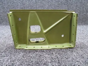
4,482 CESSNA 182F Skylane parts for sale
See all →

Parts listed for sale by vetted eBay sellers — confirmed on eBay at checkout.