Airworthiness Approval of Synthetic Vision Guidance System
CESSNA 185 · Advisory Circular
Overview
This document is an Advisory Circular (AC) from the FAA, specifically AC 20-185, which provides guidance for obtaining airworthiness approval for the installation of Synthetic Vision Guidance Systems (SVGS) in aircraft. It is intended for aircraft manufacturers, modifiers, and type certification engineers who are seeking certification or installation guidance for SVGS. The AC outlines the necessary airworthiness package, performance requirements, and evaluation criteria for SVGS installations, focusing on compliance with RTCA DO-359 standards. It is crucial for ensuring that SVGS systems meet the necessary performance and operational standards for safe flight operations, particularly in relation to Special Authorization Category I Instrument Landing System approaches.
- The AC provides guidance for airworthiness approval of Synthetic Vision Guidance Systems (SVGS) in aircraft.
- It is specifically applicable to aircraft manufacturers and type certification engineers.
- The document outlines the necessary airworthiness package contents for SVGS installations.
- Performance verification criteria for SVGS are based on RTCA DO-359 standards.
- Appendix A includes a sample AFM supplement for SVGS installations.
Document
Source
Originally published by www.faa.gov. Sprinkle hosts a reference copy with an added summary, specifications and searchable full text.
Document details
- Type
- Advisory Circular
- Year
- 2015
- Pages
- 13
- File size
- 90 KB
- Publisher
- www.faa.gov
Common. Rarer than 1% of the aircraft models we track.
Most owners only have the POH. Here's the essential set for the CESSNA 185.
- Pilot's Operating Handbook / AFM
- Checklist
- Maintenance Manual
- Parts Catalog (IPC)
- Systems & Wiring
- Service Bulletins
- Type Certificate (TCDS)
CESSNA 185 for sale now
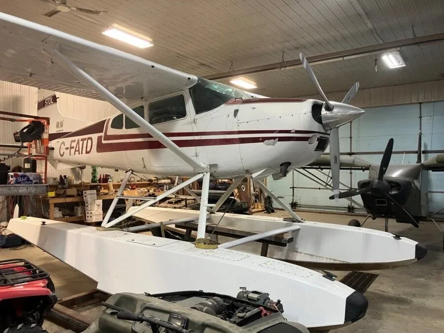

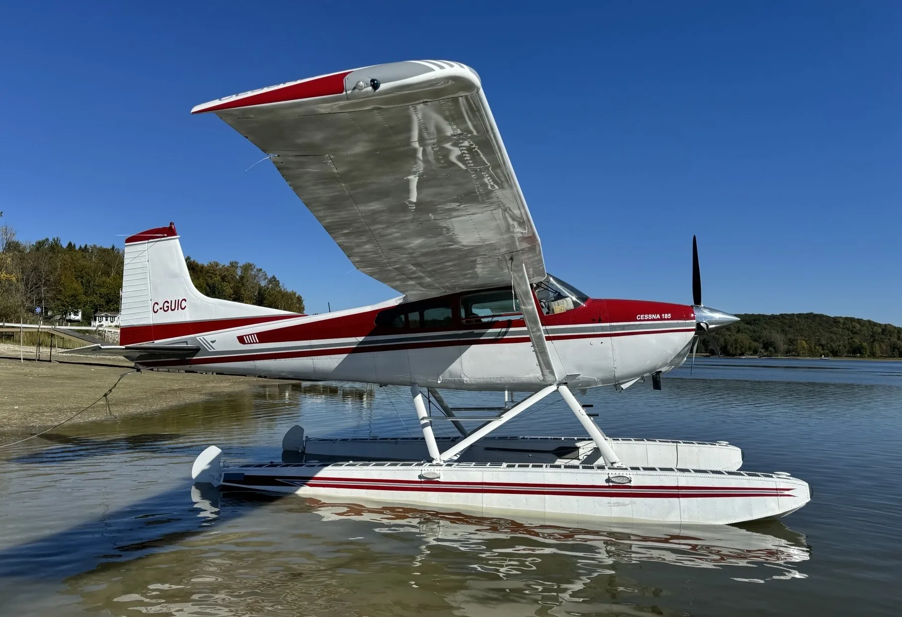
Free — save the 185 to your watchlist and track it in one place.
More CESSNA 185manuals & documents
See all 40 →- Service Bulletin No. SB24-01 | Aircraft SpruceService Bulletins
- Cessna 185 Training ManualTraining Manual
- Ethernet Media Specifications Technical DataSpecifications
- Weight & Balance - ForeFlightWeight And Balance
- SUPERVISORY HANDBOOK ON THE VALIDATION OF IRB RATING SYSTEMSOther Documents
- PARTS MANUAL 4000 FLOATS ON CESSNA 185 & 206 SERIESAvionics Manual
- MICRO SWITCH V15 Series Basic Switch DatasheetSpecifications
- Airworthiness Approval of Synthetic Vision SystemsAdvisory Circular
- SERVICE MANUAL FOR THE WIPLINE MODEL 4000 AMPHIBIOUS ...Maintenance Manual
- Airplane Flight Manual Supplement Revision ListFlight Manual
- INSTALLATION INSTRUCTIONS SUPPLEMENTAL TYPE CERTIFICATE SA04491CHFlight Manual
- COST-EFFECTIVE RADIO COMMUNICATIONSpecifications
If you fly the CESSNA 185, you may also be researching these.



In this document
Introduction
The introduction outlines the purpose of the AC, which is to provide guidance for airworthiness approval of SVGS in aircraft. It emphasizes that while the AC provides acceptable means for installation, it does not constitute a regulation. It also clarifies that existing ACs address various aspects of flight guidance systems and that this AC specifically focuses on SVGS.
Airworthiness Package
This section details the contents required in the airworthiness package for SVGS installations. Applicants must define the intended function of the SVGS and ensure compliance with performance requirements as outlined in RTCA DO-359.
SVGS System Criteria
General criteria and performance requirements for SVGS are discussed, including the need for a radio altimeter for certain approaches and the importance of maintaining updated terrain and obstacle databases.
Performance Verification
The performance verification section outlines the criteria for demonstrating the system's performance, including testing under various conditions and ensuring compliance with regulatory standards.
Appendix A: Sample AFM Supplement
Appendix A provides a sample Airplane Flight Manual (AFM) supplement for SVGS installations, detailing the necessary information that must be included for compliance and operational guidance.
Safety notes
- The FAA does not authorize the use of SVGS systems to descend below 200 feet HAT on GPS-based approaches.
- Valid and compatible databases must be installed and contain current data for the SVGS to function correctly.
Full document text
U.S. Department of Transportation Advisory Federal Aviation Administration Circular Subject: Airworthiness Approval of Synthetic Date: 12/17/15 AC No: 20-185 Vision Guidance System Initiated By: AIR-100 INTRODUCTION 1.1 Purpose. 1.1.1 In this advisory circular (AC), the Federal Aviation Administration (FAA) provides applicants with guidance for obtaining airworthiness approval for equipment installation of a Synthetic Vision Guidance System (SVGS) in aircraft. This AC only provides airworthiness guidance to applicants for eligible SVGS for use on Special Authorization (SA) Category (CAT) I Instrument Landing System (ILS) approaches. Operational approval must still be obtained from the Flight Standards Service. 1.1.2 RTCA DO-359, Minimum Aviation System Performance Standards (MASPS) for Synthetic Vision Guidance Systems, May 18, 2015, provides the minimum performance requirements for an SVGS. Although DO-359 provides guidance for SVGS presentation on the Head Down Display (HDD) or Head Up Display (HUD), and cites use on ILS, LPV or GLS based instrument approach procedures, This AC only provides airworthiness guidance to applicants for eligible SVGS for SA CAT I ILS instrument approach procedures. 1.1.3 At this time, the FAA is not authorizing the use of SVGS as the means to descend below 200 feet HAT on LPV or GLS instrument approach minimums. Installation guidance for systems used to fly LPV or GLS based approaches can be found in the current version of AC 20-138, Airworthiness Approval of Positioning and Navigation Systems. 1.1.4 Existing ACs address flight guidance symbology, HUD and visual display characteristics (for example, AC 25-11B, Electronic Flight Deck Displays, AC 25.1329- 1C, Approval of Flight Guidance Systems, and AC 23.1311-1C, Installation of Electronic Display in Part 23 Airplanes, and AC 20-167, Airworthiness Approval of Enhanced Vision System, Synthetic Vision System, Combined Vision System, and 12/17/15 AC 20-185 Enhanced Flight Vision System Equipment). This AC addresses airworthiness guidance for SVGS, and planned revisions will consolidate synthetic vision criteria. 1.1.5 This AC only applies to SVGS as part of an installed PFD. It is not mandatory and does not constitute a regulation. This AC describes an acceptable means, but not the only means, to install and obtain airworthiness approval of equipment installation of SVGS. However, if you use the means described in this AC, you should follow it in all aspects. 1.2 AC Applicability. 1.2.1 This AC is for aircraft manufacturers, modifiers, and type certification engineers seeking certification or installation guidance for their SVGS. This AC applies to all applicants for a new type certificate (TC), an amended type certificate (ATC), or a supplemental type certificate (STC), to install SVGS. The method of compliance described in this AC can be used to obtain a TC, STC, or ATC for an airplane or rotorcraft equipped with SVGS equipment. 1.2.2 This AC does not address operational aspects of SVGS or any changes in aircraft operational capability that may result from installation of these systems. 1.3 How to Use this Document. 1.3.1 This AC references RTCA/DO-359, Minimum Aviation System Performance Standards (MASPS) for Synthetic Vision Guidance Systems. RTCA/DO-359 is copyrighted by RTCA, Inc. and used with permission. 1.3.2 This AC provides methods, procedures, and practices acceptable to the FAA for complying with regulations. This material does not alter regulatory requirements. 1.3.3 Appendix A outlines a sample airplane flight manual (AFM) supplement. Appendix B contains acronym references and document purchase information. Appendix C lists documents referenced in this AC. Appendix D provides the Advisory Circular Feedback Form. 2 12/17/15 AC 20-185 CHAPTER 2. AIRWORTHINESS PACKAGE 2.1 Airworthiness Package. The applicant is responsible for the following contents in the airworthiness package (for the purpose of this AC). This AC specifically addresses SVGS installations. 2.1.1 Intended Function: The applicant should clearly define the intended function of the SVGS. RTCA DO-359 paragraph 1.4 provides examples of a minimum set of intended functions. The list of intended functions found in RTCA DO-359 is not an exhaustive list and the applicant must ensure the intended functions provided support the specific SVGS submitted for airworthiness approval. 2.1.2 General Operations: General system criteria for the minimum performance of SVGS is found in section 2 of RTCA DO-359. SVGS standard performance requirements are found in RTCA DO-359 section 3. 2.1.3 Performance Requirements and Evaluation Criteria: Guidance on performance requirements are in Chapter 4 and SVGS performance verification in evaluation are in chapter 5 of this AC. CHAPTER 3. INTRODUCTION TO SYNTHETIC VISION GUIDANCE SYSTEM (SVGS) 3.1 SVGS Overview. 3.1.1 RTCA DO-359 describes SVGS as a combination of Synthetic Vision System (SVS) and flight guidance displayed on the primary flight display (PFD), and high precision position assurance monitors. The SVGS flight instrument display provides a continuous, geo-spatially correct depiction of the external scene topography, including obstacles, augmented by the display of the runway of intended landing. The SVGS display is implemented on a head-down or head up PFD, designed to the guidance provided by AC 25-11B. SVGS includes additional symbology elements, integrity and performance monitors and annunciations. 3.1.2 The basic system description and overview of the SVGS and basic system architecture can be found in section 1.2 of RTCA DO-359. CHAPTER 4. SVGS SYSTEM CRITERIA 4.1 SVGS General Criteria and Standard Performance Requirements. 4.1.1 General performance requirements for SVGS can be found in section 2 of RTCA/DO- 359. Specific performance requirements can be found in RTCA/DO-359 Section 3. 3 12/17/15 AC 20-185
Show full textShow less
4.2 Additional Notes to section 2 and section 3 of RTCA DO-359. 4.2.1 Unless specifically addressed in RTCA/DO-359 all of the requirements for SVS listed in AC 20-167 apply. 4.2.2 The FAA does not currently authorize the use of an SVGS system as a suitable means to fly to a HAT below 200 feet on a GPS based instrument approach. 4.2.3 If the applicant implements SVGS only on a HDD, the aircraft should be capable to displaying the SVGS simultaneously on the PFD of the pilot flying and the pilot not flying. 4.2.4 DO-359 in section 3.1.6 requires the use of a radio altimeter or equivalent. Currently, all published SA CAT I ILS procedures require the use of a radio altimeter. 4.2.5 The terrain, runway and obstacle database requirements for the SVGS system specified in RTCA/DO-359, section 2.5 must support intended function and the processes for their production and update must be compliant with RTCA/DO-200B, Standards for Processing Aeronautical Data, dated June 18, 2015, or subsequent revisions. Navigation databases supporting creation of the SVS image must be compliant with the requirements of RTCA/DO-201A, Standards for Aeronautical Information, dated April 19, 2000, or subsequent revisions. Terrain and obstacle databases supporting creation of the SVS image must use RTCA/ DO-276C, User Requirements for Terrain and Obstacle Data, dated September 22, 2015, or subsequent revisions, to define data quality requirements (DQRs) adequate to support intended function. Terrain and obstacle databases supporting creation of the SVS image for operations in the terminal environment must meet the requirements of RTCA/ DO-276C, Section 4.4. 4.2.6 When the applicant develops the design of the SVGS certified under part 25 the applicant should reference AC 25.1302, Installed Systems and Equipment for Use by the Flight Crew. 4.2.7 Continued Airworthiness and Maintenance. The applicant must develop instructions for continued airworthiness for the SVGS and its components to show compliance with 14 CFR Parts 23.1529, 25.1529, 27.1529 and 29.1529 dependent on the original certification of the host aircraft. Other maintenance tasks may be developed as a result of the safety assessment, design reviews, manufacture’s recommendations and Maintenance Steering Group 3 (MSG-3) analyses that are conducted. These instructions include, but are not limited to removal and replacement, troubleshooting, cleaning, maintenance procedures for the MEL relief and software loading/configuration control. 4 12/17/15 AC 20-185 CHAPTER 5. SVGS PERFORMANCE VERIFICATION 5.1 Performance Demonstration Overview. 5.1.1 RTCA/DO-359 section 4 provides system performance verification criteria. The following performance verification procedures found in this paragraph are based on RTCA/DO-359 section 4, except “must” is replaced with “should”. 5.1.2 The performance evaluations should include demonstrations of all approach types requested, missed approaches, failure conditions, cross wind conditions, and approaches into various ground facilities as required to demonstrate the system’s intended function. 5.1.3 In addition to the test conditions listed in DO-359 section 4.2.2 the applicant should also demonstrate their system in representative day and night VMC conditions. 5.1.4 The applicant should also demonstrate performance at the lateral and vertical limits for the type of approach for which credit is being sought. 5.1.5 Where appropriate for the performance demonstration, the non-visual conditions can be achieved either by natural obscuration or by use of a visibility limiting device in front of the pilot. 5.1.6 The use of a simulator can be considered, provided the simulator has been assessed to adequately conform with respect to the aircraft and the SVGS performance, and has been assessed to be suitable for the required task. 5.1.7 The workload associated with using the SVGS to fly SVGS approaches to a missed approach point of 150 feet HAT should be considered when showing compliance with 14 CFR 23.1523, 25.1523, 27.1523, 29.1523 and AC 23.1523, AC 25.1523, AC 27-1B, AC 29-2C as applicable to the aircraft in which the SVGS is being installed. Susan J. M. Cabler Acting Manager, Design, Manufacturing, & Airworthiness Division Aircraft Certification Service 5 12/15 AC 20-185 Appendix A APPENDIX A. SAMPLE AIRPLANE FLIGHT MANUAL (AFM) SUPPLEMENT Note: This appendix presents a sample for the AFM supplement for STC installations. This example may not be entirely applicable to airplane manufacturers when SVGS is approved with the type certificate. Installation Center/Repair Station Model XXX SVGS 123 Fourth Street Vision System Anytown, USA FAA APPROVED AIRPLANE FLIGHT MANUAL SUPPLEMENT ABC MODEL XXX YYY SYNTHETIC VISION GUIDANCE SYSTEM AIRPLANE MAKE: AIRPLANE MODEL: AIRPLANE SERIAL NO.: REGISTRATION NO.: This document must be carried in the airplane at all times. It describes the operating procedures for the ABC Model XXX YYY SVGS when it has been installed in accordance with <manufacturer's installation manual number and date>. For airplanes with an FAA Approved Airplane Flight Manual, this document serves as the FAA Approved ABC Model XXX YYY Flight Manual Supplement. For airplanes that do not have an approved flight manual, this document serves as the FAA Approved ABC Model XXX YYY Supplemental Flight Manual. The information contained herein supplements or supersedes the basic Airplane Flight Manual dated only in those areas listed herein. For limitations, procedures, and performance information not contained in this document, consult the basic Airplane Flight Manual. FAA APPROVED ____________________ Title Office Federal Aviation Administration City, State 6 12/15 AC 20-185 Appendix A Installation Center/Repair Station Model XXX SVGS 123 Fourth Street Vision System Anytown, USA Table of Contents Section...............................................Page 1 General.............................................< > 2 Limitations........................................< > 3 Emergency/Abnormal Procedures....< > 4 Normal Procedures...........................< > 5 Performance......................................< > 6 Weight and Balance..........................< > 7 System Description...........................< > FAA Approved Page <> of <> Date: ________ 7 12/15 AC 20-185 Appendix A Installation Center/Repair Station Model XXX SVGS 123 Fourth Street Vision System Anytown, USA SECTION 1 - GENERAL <Include the appropriate statement to describe the equipment capability: > SVGS: The installed SVGS has been demonstrated to meet the criteria for AC 20-SVGS for SVGS to be used for DH no lower than 150 feet HAT. SECTION 2 - LIMITATIONS 1. The ABC Model XXX YYY Quick Reference Guide, P/N <insert part number>, dated <insert date> (or later appropriate revision) must be immediately available to the flight crew whenever navigation is predicated on the use of the system. 2. The system must utilize software version <insert version identification>. 3. Valid and compatible databases must be installed and contain current data. <The terrain, runway and obstacle database requirements must support the intended function applicable to the particular installation..> 4. The <Insert model specific identification> meets certification requirements of AC 20-185. However this does not constitute operational approval for use. 5. <Specify any additional limitations applicable to the particular installation.> SECTION 3 - EMERGENCY/ABNORMAL PROCEDURES EMERGENCY PROCEDURES <Specify any procedures that specific to the installation> ABNORMAL PROCEDURES FAA Approved Page <> of <> 8 12/15 AC 20-185 Appendix A Date: ________ 1. If ABC Model XXX YYY vision system information is not available or invalid, utilize remaining operational navigation equipment as appropriate. 2. If Loss of Integrity Monitoring message is displayed, revert to an alternate means of navigation appropriate to the route and phase of flight or periodically cross-check the GPS guidance to other, approved means of navigation. SECTION 4 - NORMAL PROCEDURES 1. Normal operating procedures are outlined in the ABC Model XXX YYY Pilot's Guide. 2. System Annunciators <applicable to installations with external annunciators> 3. System Switches <applicable to installations with external switches> 4. Pilot's Display <describe the pilot's display(s)> 5. Flight Director/Autopilot Coupled Operation <describe any procedures for integrated flight director and/or autopilot system(s)> 6. <include any other normal operating procedures as necessary> SECTION 5 - PERFORMANCE No Change SECTION 6 - WEIGHT AND BALANCE <Refer to revised weight and balance data, if applicable.> SECTION 7 - SYSTEM DESCRIPTION <Provide a brief description of the system, its operation, installation, etc.> FAA Approved Page < > of < > Date: ________ 9 12/ /15 AC 20-185 Appendix B APPENDIX B. DEFINITIONS AND DOCUMENT ORDERING B.1 Definitions. See DO-359, Appendix A B.2 How to Get Publications. Order copies of 14 CFR, from the Superintendent of Documents, Government Printing B.2.1 Office, P.O. 979050, St. Louis, MO 63197. For general information telephone (202) 512-1800 or fax (202) 512-2250. You can order copies online at www.access.gpo.gov. Select “Access” then “Online Bookstore.” Select “Aviation,” then “Code of Federal Regulations.” You can get copies of FAA AC’s from the FAA website at www.airweb.faa.gov or B.2.2 www.faa.gov/regulations_policies/adviory_circulars/. Order copies of RTCA Documents from RTCA, Inc., 1150 18 th St. NW., Suite 910, B.2.3 Washington, D.C 20036, telephone (202) 833-9339, Fax (202) 833-9434, or website: www.rtca.org. 10 12/17/15 AC 20-185 Appendix C APPENDIX C. RELATED PUBLICATIONS C.1 Federal Aviation Administration Documents Order 8400.13D, Procedures for the Evaluation and Approval of Facilities for Special C.1.1 Authorization Category I Operations and all Category II and III Operations AC 20-138D Change 1, Airworthiness of Positioning and Navigation Systems C.1.2 AC 20-153A, Acceptance of Aeronautical Data Processes and Associated Databases C.1.3 AC 20-163, Displaying Geometric Attitude Relative to Mean Sea Level C.1.4 AC 20-167, Airworthiness Approval of Enhanced Vision System, Synthetic Vision C.1.5 System, Combined Vision System, and Enhanced Flight Vision System Equipment AC 23-18, Installation of Terrain Awareness and Warning System (TAWS) Approved C.1.6 for Part 23 Airplanes AC 23.1309-1E, System Safety Analysis and Assessment for Part 23 Airplanes C.1.7 AC 23.1311-1C, Installation of Electronic Display in Part 23 Airplanes C.1.8 AC 23-1523, Minimum Flight Crew C.1.9 AC 25-11B, Electronic Flight Displays C.1.10 AC 25-19, Certification Maintenance Requirements C.1.11 AC 25-23, Airworthiness Criteria for the Installation Approval of a Terrain Awareness C.1.12 and Warning System (TAWS) for Part 25 Airplanes AC 25.1302, Installed Systems and Equipment for Use by the Flight Crew. C.1.13 AC 25.1309-1A, Certification Maintenance Requirements C.1.14 AC 25.1322-1C, Flightcrew Alerting C.1.15 AC 25.1329-1C, Approval of Flight Guidance Systems C.1.16 AC 25.1523-1, Minimum Flightcrew C.1.17 AC 27-1B, Certification of Normal Category Rotorcraft C.1.18 AC 29-1C, Certification of Transport Category Rotorcraft C.1.19 11 12/17/15 AC 20-185 Appendix C AC 120-29A, Criteria for Approval of Category I and Category II Weather Minima for C.1.20 Approach TSO-C10b, Altimeter, Pressure Actuated, Sensitive Type C.1.21 TSO-C87, Airborne Low-Range Radio Altimeter C.1.22 TSO-C106, Air Data Computer C.1.23 TSO-C145c, Airborne Navigation Sensors Using The Global Positioning System C.1.24 Augmented by the Satellite Based Augmentation System. TSO-C146c, Stand-Alone Airborne navigation Equipment Using The Global C.1.25 Positioning System Augmented By the Satellite Based Augmentation System. TSO-C151c, Terrain Awareness and Warning System (TAWS) C.1.26 C.2 RTCA Documents DO-160, Environmental Conditions and Test Procedures for Airborne Equipment C.2.1 DO-178C, Software Considerations in Airborne Systems and Equipment Certification C.2.2 RTCA DO-200B, Standards for Processing Aeronautical Data C.2.3 RTCA DO-201A, Standards for Aeronautical Information C.2.4 DO-254, Design Assurance Guidance for Airborne Electronic Hardware C.2.5 DO-276B, User Requirements for Terrain and Obstacle Data C.2.6 DO-359, Minimum Aviation System Performance Standard (MASPS) for Synthetic C.2.7 Vision Guidance Systems C.3 SAE Documents AS 8055A, Minimum Performance Standard for Airborne Head Up Display (HUD) C.3.1 AS 8034B, Minimum Performance Standard for Airborne Multipurpose Electronic C.3.2 Displays 12 12/ 17/15 AC 20-185 Appendix D APPENDIX D. ADVISORY CIRCULAR FEEDBACK FORM If you find an error in this AC, have recommendations for improving it, or have suggestions for new items/subjects to be added, you may let us know by (1) emailing this form to 9-AWA-AVS-AIR500-Coord@faa.gov or (2) faxing it to the attention of the AIR Directives Management Officer at 202-267-3983. Subject: ____________________________ Date: ____________________ Please check all appropriate line items: An error (procedural or typographical) has been noted in paragraph __________________ on page __________________________. Recommend paragraph ____________ on page ______________ be changed as follows: In a future change to this AC, please cover the following subject: (Briefly describe what you want added.) Other comments: I would like to discuss the above. Please contact me. Submitted by: __________________________________ Date: ________________________ 13
What's in the CESSNA 185 TCDS
A Type Certificate Data Sheet (TCDS) is the FAA's record of what an aircraft type was approved as. It is the source of truth for weights, seating, fuel and the rules the design was certified against. Expand any line to see what it means.
770 CESSNA 185 parts for sale
See all →


Parts listed for sale by vetted eBay sellers — confirmed on eBay at checkout.