SERVICE MANUAL FOR THE WIPLINE MODEL 4000 AMPHIBIOUS ...
CESSNA 185 · Maintenance Manual
Overview
This service manual provides comprehensive maintenance and operational guidelines for the Wipline Model 4000 amphibious and seaplane floats specifically designed for the Cessna A185E, A185F, and 206 series aircraft. It covers various aspects of float maintenance, including hull maintenance, corrosion prevention, float handling, and the operation of the retract system. The manual is intended for aircraft maintenance personnel and pilots who operate these floats, ensuring they understand the necessary procedures for safe and effective float operation and maintenance. Key sections include detailed instructions on float hull maintenance, handling and jacking procedures, and a thorough inspection checklist to ensure the integrity and safety of the float systems.
- Buoyancy: 3802 lbs (seaplane), 3672 lbs (amphibious)
- Hydraulic system pressure: 500-1000 psi for operation
- Regular cleaning after saltwater use is essential
- Corrosion detection includes visual inspection for discoloration and powdery deposits
- Follow specific jacking procedures to ensure safety during maintenance
Document
Source
Originally published by www.wipaire.com. Sprinkle hosts a reference copy with an added summary, specifications and searchable full text.
Document details
- Type
- Maintenance Manual
- Year
- 2021
- Pages
- 50
- File size
- 1.5 MB
- Publisher
- www.wipaire.com
Common. Rarer than 1% of the aircraft models we track.
Most owners only have the POH. Here's the essential set for the CESSNA 185.
- Pilot's Operating Handbook / AFM
- Checklist
- Maintenance Manual
- Parts Catalog (IPC)
- Systems & Wiring
- Service Bulletins
- Type Certificate (TCDS)
CESSNA 185 for sale now
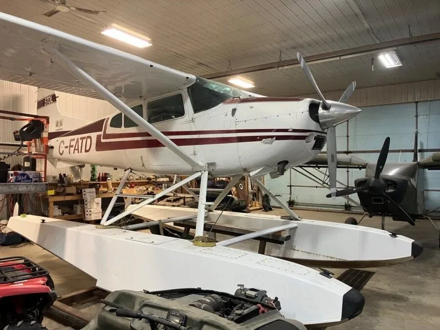

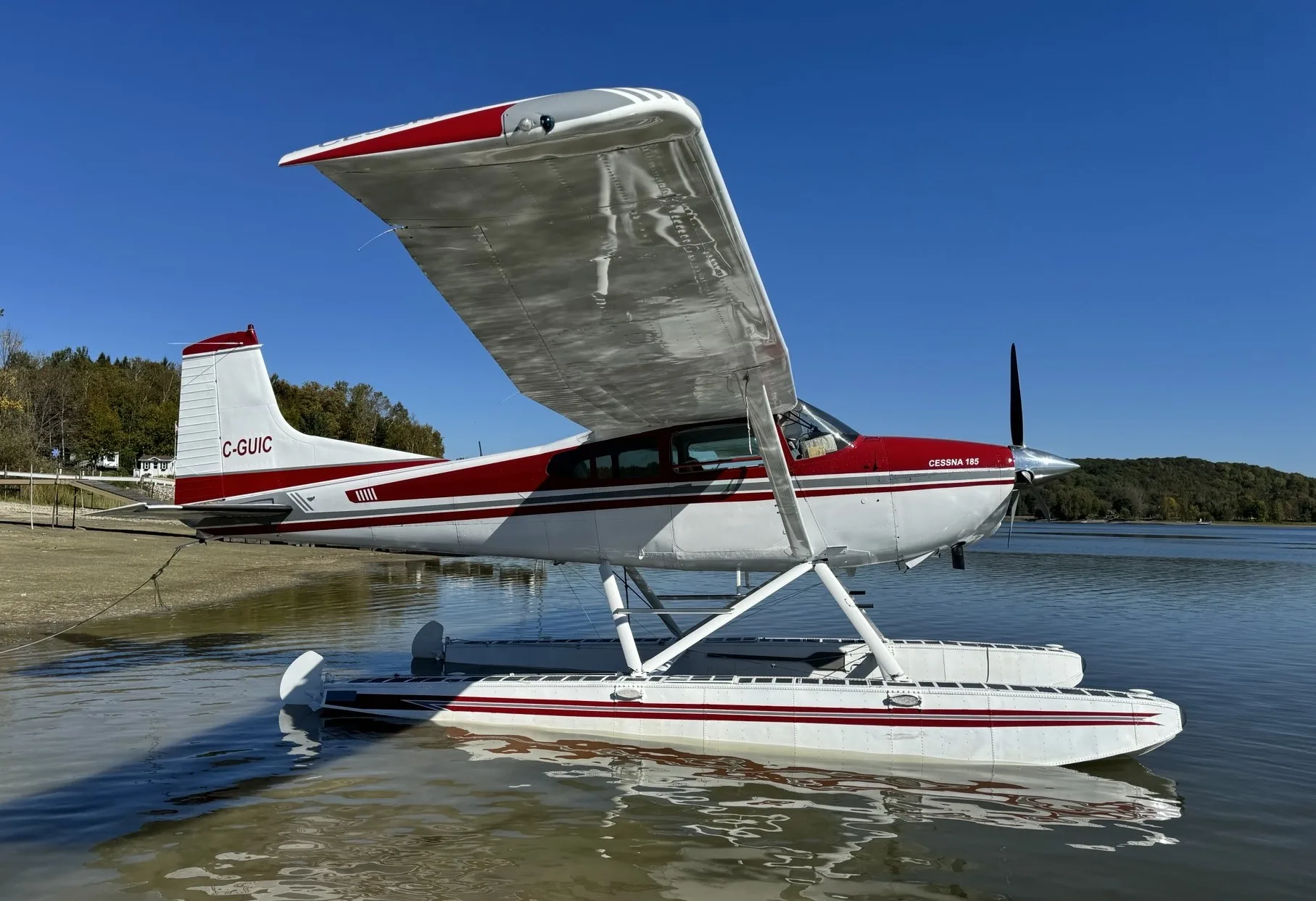
Free — save the 185 to your watchlist and track it in one place.
More CESSNA 185manuals & documents
See all 40 →- Service Bulletin No. SB24-01 | Aircraft SpruceService Bulletins
- Cessna 185 Training ManualTraining Manual
- Ethernet Media Specifications Technical DataSpecifications
- Weight & Balance - ForeFlightWeight And Balance
- SUPERVISORY HANDBOOK ON THE VALIDATION OF IRB RATING SYSTEMSOther Documents
- PARTS MANUAL 4000 FLOATS ON CESSNA 185 & 206 SERIESAvionics Manual
- MICRO SWITCH V15 Series Basic Switch DatasheetSpecifications
- Airworthiness Approval of Synthetic Vision SystemsAdvisory Circular
- Airplane Flight Manual Supplement Revision ListFlight Manual
- INSTALLATION INSTRUCTIONS SUPPLEMENTAL TYPE CERTIFICATE SA04491CHFlight Manual
- COST-EFFECTIVE RADIO COMMUNICATIONSpecifications
- mr. thomas anderson - McFarlane AviationService Manual
If you fly the CESSNA 185, you may also be researching these.



In this document
General Information
The Wipline Model 4000 floats are constructed from aluminum and designed for both seaplane and amphibious operations. Each float provides a buoyancy of 3802 pounds for seaplane configurations and 3672 pounds for amphibious configurations. The floats feature a cable-operated water rudder system and a hydraulically actuated landing gear system, with dual tires on the main gear and a single tire on the nose gear.
Float Hull Maintenance
The float structure is made from corrosion-resistant aluminum and requires regular cleaning and maintenance to prevent corrosion. The manual outlines procedures for cleaning, including washing with soap and water, and flushing the interior if saltwater enters. It emphasizes the importance of maintaining the exterior finish to protect against corrosion.
Corrosion
Corrosion detection and prevention are critical for float maintenance. The manual provides guidelines for identifying corrosion, including visual signs such as discoloration and powdery deposits. It details methods for treating light to severe corrosion and stresses the importance of regular inspections and maintenance to prevent corrosion-related damage.
Float Handling and Jacking
This section provides detailed procedures for towing, hoisting, and jacking the aircraft equipped with Wipline floats. It includes safety precautions and step-by-step instructions for safely lifting and securing the floats during maintenance.
Retract System Operation and Maintenance
The retract system for the landing gear is hydraulically operated and includes a detailed description of its components and operation. The manual specifies the pressure ranges for operation and provides troubleshooting tips, maintenance schedules, and inspection guidelines for the hydraulic system.
Safety notes
- Ensure nothing is under or above the aircraft when hoisting or jacking.
- Verify landing gear is down and locked before removing jacks.
Full document text
SERVICE MANUAL & ICA WIPLINE 4000 FLOATS ON CESSNA A185E, A185F, AND 206 SERIES P/N 1002552 Revision G Page 1 SERVICE MANUAL FOR THE WIPLINE MODEL 4000 AMPHIBIOUS AND SEAPLANE FLOATS ON CESSNA A185E, A185F, AND 206 SERIES Revision G WIPLINE FLOATS • SKIS • MODIFICATIONS • AIRCRAFT SALES AVIONICS • INTERIOR • MAINTENANCE • PAINT REFINISHING SERVICE MANUAL & ICA WIPLINE 4000 FLOATS ON CESSNA A185E, A185F, AND 206 SERIES Page 2 Revision G P/N 1002552 THIS PAGE INTENTIONALLY LEFT BLANK SERVICE MANUAL & ICA WIPLINE 4000 FLOATS ON CESSNA A185E, A185F, AND 206 SERIES P/N 1002552 Revision G Page 3 LOG OF REVISIONS Rev Pages Description Date A 9, 22 Added an inspection time limit and tolerances for the Nose Block Track wear. 4/18/2006 B All Reformat of entire document, Add green grease as approved grease. 4/16/2013 C 13-14 Added Shear Torque Chart, PR 1440 C Sealant and Tef-Gel, removed Warranty Claim Form. 5/26/2015 D 5, 13-14 Added Dow Corning DC4, Corrosion X, and Mobil Aviation Grease SHC 100 to approved product list. Modified torque limit section. 12/4/2015 E 8 Added reference for Structural Repair Manual part number 1008274 in introduction. 5/1/2019 F 10, 13, 15-17, 29 Added information about corrosion limits. Added note about STA-Lube. Removed inspection column from Maintenance Checklist. Added STA-Lube to Brake Caliper Grease. 8/3/2020 G All Reformatted manual in new software. Updated title page and headers. Added sections 4.0 through 4.4. Removed Comet Industries GP-730A. Removed content in Chapters 9 and 10 and replaced with note about SRM. Removed Figures 9-1 through 9-6 and Figures 10-1 through 10-3 as content is found in SRM. 2/3/2021 View most current revision of this ICA at www.wipaire.com. SERVICE MANUAL & ICA WIPLINE 4000 FLOATS ON CESSNA A185E, A185F, AND 206 SERIES Page 4 Revision G P/N 1002552 THIS PAGE INTENTIONALLY LEFT BLANK SERVICE MANUAL & ICA WIPLINE 4000 FLOATS ON CESSNA A185E, A185F, AND 206 SERIES P/N 1002552 Revision G Page 5 CONTENTS INTRODUCTION ...............................................................................................................................................7 CHAPTER 1 GENERAL INFORMATION .........................................................................................................9 CHAPTER 2 FLOAT HULL MAINTENANCE .................................................................................................11 CHAPTER 3 CORROSION .............................................................................................................................13 CHAPTER 4 FLOAT HANDLING AND JACKING ..........................................................................................15 CHAPTER 5 RETRACT SYSTEM OPERATION AND MAINTENANCE ......................................................21 CHAPTER 6 MAIN GEAR ...............................................................................................................................39 CHAPTER 7 NOSE GEAR ..............................................................................................................................43 CHAPTER 8 WATER RUDDER RETRACTION AND STEERING SYSTEM ...............................................45 CHAPTER 9 REPAIRING FLOAT HULL SKINS ............................................................................................47 CHAPTER 10 REPAIRING FLOAT HULL EXTRUSIONS .............................................................................49 SERVICE MANUAL & ICA WIPLINE 4000 FLOATS ON CESSNA A185E, A185F, AND 206 SERIES Page 6 Revision G P/N 1002552 LIST OF FIGURES FIGURE 4-1 JACK CRADLE RECOMMENDED MODIFICATION ........................................................17 FIGURE 4-2 JACKING LOCATION .........................................................................................................17 FIGURE 4-3 FLOAT SECURING LOCATIONS ......................................................................................18 FIGURE 4-4 FLOAT SECURING LOCATIONS OVERVIEW .................................................................19 FIGURE 5-1 SCHEMATIC HYDRAULIC SYSTEM ................................................................................23 FIGURE 5-2 SCHEMATIC: LANDING GEAR ELECTRICAL SYSTEM ................................................24 FIGURE 5-3 MAIN GEAR ACTUATION SYSTEM ..................................................................................25 FIGURE 5-4 MAIN GEAR LOCKING SYSTEM ......................................................................................26 FIGURE 5-5 NOSE GEAR RETRACTION SYSTEM .............................................................................27 FIGURE 6-1 SECTION MAIN GEAR OLEO ...........................................................................................40 FIGURE 6-2 ASSEMBLY MAIN WHEEL AND BRAKE ...........................................................................42 SERVICE MANUAL & ICA WIPLINE 4000 FLOATS ON CESSNA A185E, A185F, AND 206 SERIES P/N 1002552 Revision G Page 7 This manual describes the general service and maintenance for the float hull, gear systems, installation, and control parts. For service and repair not covered by this manual contact Wipaire Customer Service. When performing standard repairs for Wipline Aluminum Floats, please refer to the “Structural Repair Manual For Wipline Aluminum Floats” part number 1008274. It is available free of charge online at www.wipaire.com. The service products referred to throughout this manual are described by their trade name and may be purchased from the Wipaire Parts Department. To contact Wipaire for technical support or parts sales call write or email: Wipaire, Inc. Customer Service 1700 Henry Avenue – Fleming Field South St. Paul, MN 55075 Phone: (651) 306-0459 Fax: (651) 306-0666 Website: www.wipaire.com Email: CustomerService@wipaire.com INTRODUCTION SERVICE MANUAL & ICA WIPLINE 4000 FLOATS ON CESSNA A185E, A185F, AND 206 SERIES
Show full textShow less
Page 8 Revision G P/N 1002552 THIS PAGE INTENTIONALLY LEFT BLANK SERVICE MANUAL & ICA WIPLINE 4000 FLOATS ON CESSNA A185E, A185F, AND 206 SERIES P/N 1002552 Revision G Page 9 CHAPTER 1 GENERAL INFORMATION CONTENTS 1.0 GENERAL ..................................................................................................................................................10 SERVICE MANUAL & ICA WIPLINE 4000 FLOATS ON CESSNA A185E, A185F, AND 206 SERIES Page 10 Revision G P/N 1002552 1.0 GENERAL The model 4000 seaplane or amphibious float is an all aluminum constructed float with watertight compartments. The actual displacement in fresh water for each float is 3802 pounds buoyancy for the seaplane and 3672 pounds buoyancy for the amphibian. The amphibian float is geometrically the same as the seaplane except for the addition of landing gear and internal structure for the gear. The water rudder system is cable operated with ball bearing pulleys. Water rudder cables tie into the existing aircraft rudder system. The main landing gear has dual 5.00 x 5 6-ply tires and the nose landing gear has one 4.10 x 4 4-ply tire. The gear system is hydraulically actuated and driven by one pump located on the engine firewall on a Cessna 185 and in the aft fuselage at Sta. 159.3 on a Cessna 206. Brakes are hydraulic and have a caliper on each main wheel for a total of four brakes. Steering on land is accomplished by differential braking. The nose wheels are full castering. Access to the float interior is accomplished by removing covers on the top deck and four covers inside the wheel well. When necessary, water inside the float hulls may be removed through pump out cups located on the outboard edge of each float top skin. SERVICE MANUAL & ICA WIPLINE 4000 FLOATS ON CESSNA A185E, A185F, AND 206 SERIES P/N 1002552 Revision G Page 11 CHAPTER 2 FLOAT HULL MAINTENANCE CONTENTS 2.1 GENERAL ..................................................................................................................................................12 2.2 CLEANING .................................................................................................................................................12 SERVICE MANUAL & ICA WIPLINE 4000 FLOATS ON CESSNA A185E, A185F, AND 206 SERIES Page 12 Revision G P/N 1002552 2.1 GENERAL The float structure is manufactured entirely of 2024-T3 or 6061-T6 corrosion resistant aluminum sheet and extrusions. Skins on the inside are primed with a 3M SCOTCHWELD primer after being cleaned and acid-etched. Exterior surfaces are cleaned and alodined. Surfaces are then primed with an epoxy-based primer and finished with an enamel color paint. 2.2 CLEANING The outside of the float should be kept clean by washing with soap and water, with special care taken to remove engine exhaust trails, water line marks, and barnacle deposits. After salt water operation, washing with fresh water should be done daily with special attention to hard-to reach places, such as seams, wheel well, etc. The float interior should be flushed if salt water enters the compartments. If storing inside, remove inspection covers so interior will dry. SERVICE MANUAL & ICA WIPLINE 4000 FLOATS ON CESSNA A185E, A185F, AND 206 SERIES P/N 1002552 Revision G Page 13 CHAPTER 3 CORROSION CONTENTS 3.0 CORROSION .............................................................................................................................................14 SERVICE MANUAL & ICA WIPLINE 4000 FLOATS ON CESSNA A185E, A185F, AND 206 SERIES Page 14 Revision G P/N 1002552 3.0 CORROSION Reference the Wipaire Structural Repair Manual (SRM) for allowable corrosion/material loss limits. Corrosion is a reaction that destroys metal by an electrochemical action that converts metal to oxide. Corrosion is accelerated when in contact with dissimilar metals such as aluminum and steel, or any material which absorbs moisture like wood, rubber, or dirt. The primary means of detection of corrosion is visual. The most obvious sign is a corrosive deposit of white powder. Other signs are discoloration of the metal surface or bubbles and blisters under the painted surface. Light corrosion may be removed by light hand sanding or chromic acid. Moderate and severe corrosion (blistering, flaking, and pitting) may be removed by heavy sanding or grinding, and applying chromic acid. No more than 1/3rd the thickness of skin material should be removed before complete replacement or reinforcement of an area is necessary. After removing the corroded area, restore area to original finish (prime and enamel). BOESHIELD T9, Corrosion X, or ACF-50 may also be applied to stop corrosion. Refer to manufacturer’s instructions for application instructions. Maintaining the float inside and outside finishes by washing after saltwater operations will help protect the float from corrosion. Periodically, all hardware should be covered with a waterproof grease, or paralketone. Under saltwater conditions, bolts should be removed at least once a year and grease reapplied to the shafts, heads and nuts. SERVICE MANUAL & ICA WIPLINE 4000 FLOATS ON CESSNA A185E, A185F, AND 206 SERIES P/N 1002552 Revision G Page 15 CHAPTER 4 FLOAT HANDLING AND JACKING CONTENTS 4.0 TOWING .....................................................................................................................................................16 4.1 HOISTING ..................................................................................................................................................16 4.2 LEVELING .................................................................................................................................................16 4.3 JACKING PROCEDURES ........................................................................................................................16 4.4 JACK REMOVAL .......................................................................................................................................19 SERVICE MANUAL & ICA WIPLINE 4000 FLOATS ON CESSNA A185E, A185F, AND 206 SERIES Page 16 Revision G P/N 1002552 4.0 TOWING When towing the amphibian aircraft, 2 lugs are provided on the lower forward side of the nose spring. On land, a rigid “V” frame can be fabricated to attach to these lugs for towing the aircraft with a tractor. Lake & Air Training and Pilot Shop has this tow bar available for purchase. On water, a rope bridle arrangement can used to tow the aircraft from the lugs described above. 4.1 HOISTING Hoisting the aircraft can be performed using a lifting rig that attaches to the aircraft with lifting rings that are installed at the wing attach points. If the lifting rings are not installed, reference applicable aircraft maintenance/ service manual for additional hoisting specifications. Lake & Air Training and Pilot Shop has this hoisting rig available for purchase. Contact Wipaire Customer Service for additional guidance in removal or installation of floats. CAUTION! Make sure nothing is under or above the airplane or floats when hoisting the aircraft 1. Raise aircraft high enough to place float cradle under floats as shown in Figure 4-4. 2. Lower aircraft onto float cradle as shown in Figure 4-4. 3. Place fore and aft supports as shown in Figure 4-3 and Figure 4-4. 4.2 LEVELING See applicable aircraft maintenance/service manual. 4.3 JACKING PROCEDURES CAUTION! Make sure nothing is under or above the airplane or floats when jacking the aircraft. 1. Turn off fuel. 2. Place weighted bags above the nose gear (approximately 100 lbs. on each float to start, more may be added as needed). 3. Position 1 person at each fore and aft of each float, and 3 people at the jacking location of one float. 4. Modify jack saddle of a 3 ton minimum jack by welding as shown in Figure 4-1. SERVICE MANUAL & ICA WIPLINE 4000 FLOATS ON CESSNA A185E, A185F, AND 206 SERIES P/N 1002552 Revision G Page 17 (X = WIDTH OF CRADLE) FIGURE 4-1 JACK CRADLE RECOMMENDED MODIFICATION NOTE: This is not required and Wipaire does not have the parts for modification. It is recommended a similar modification be performed to the jack saddle to prevent the slippage of the cradle. 1. Center cradle on saddle and position so cradle is as far aft on the main keel as possible without interfering with main gear as it decompresses as shown in Figure 4-2. NOTE: If desired to prevent possible cosmetic damage to float, use material to separate cradle and float. FIGURE 4-2 JACKING LOCATION 1. Jack one side at a time, taking care to check the balance of the aircraft and adding more weight to the front if needed. 2. Two people, both outboard, lift the fore and aft cradle stands up to the cradle as a 3rd person release the pressure slowly, allowing the cradle and stands to gently contact the ground. 3. Repeat previous procedure to the other float. NOTE: A smaller jack may be needed to slightly lift the float into a high enough position for the main jack. 4. Secure floats with fore and aft supports as shown in Figure 4-3 and Figure 4-4. SERVICE MANUAL & ICA WIPLINE 4000 FLOATS ON CESSNA A185E, A185F, AND 206 SERIES Page 18 Revision G P/N 1002552 FIGURE 4-3 FLOAT SECURING LOCATIONS ALTERNATE JACKING METHOD IF WIPAIRE JACKING FIXTURE IS NOT AVAILABLE (8000A model shown for reference only) SERVICE MANUAL & ICA WIPLINE 4000 FLOATS ON CESSNA A185E, A185F, AND 206 SERIES P/N 1002552 Revision G Page 19 Aft Cradle Stand Fore Cradle Stand Cradle Fore Support Aft Support (8000A MODEL SHOWN FOR REFERENCE ONLY) FIGURE 4-4 FLOAT SECURING LOCATIONS OVERVIEW 4.4 JACK REMOVAL Make sure nothing is under or above the airplane or floats when removing the jacks from the aircraft 1. Turn off fuel. 2. Verify landing gear is in the down and locked position. 3. Verify weighted bags are still located above the nose gear. 4. Position 1 person at each fore and aft of each float, and 1 person at the jacking location of one float. 5. Remove all fore and aft supports as shown in Figure 4-3 and Figure 4-4. 6. Using modified jack saddle as shown in Figure 4-1, center jack saddle in center of cradle on 1 of the floats, 7. Lift aircraft to clear fore and aft cradle stands and remove fore and aft cradle stands of lifted float. 8. Slowly lower float to the ground, remove jack from under float, and remove cradle from jack saddle. 9. Repeat previous procedure to the other float. 10. Remove weighted bags from floats. SERVICE MANUAL & ICA WIPLINE 4000 FLOATS ON CESSNA A185E, A185F, AND 206 SERIES Page 20 Revision G P/N 1002552 THIS PAGE INTENTIONALLY LEFT BLANK SERVICE MANUAL & ICA WIPLINE 4000 FLOATS ON CESSNA A185E, A185F, AND 206 SERIES P/N 1002552 Revision G Page 21 CHAPTER 5 RETRACT SYSTEM OPERATION AND MAINTENANCE CONTENTS 5.1 DESCRIPTION AND OPERATION ..........................................................................................................22 5.2 ADJUSTMENT / TEST ..............................................................................................................................28 5.3 SERVICE SCHEDULE ..............................................................................................................................28 5.4 INSPECTION CHECKLIST.......................................................................................................................32 5.5 TROUBLE SHOOTING .............................................................................................................................36 SERVICE MANUAL & ICA WIPLINE 4000 FLOATS ON CESSNA A185E, A185F, AND 206 SERIES Page 22 Revision G P/N 1002552 Retraction and extension of the main and nose landing gear is effected by a hydraulic actuation system shown schematically in figure 5-1. The gear system is hydraulically actuated and driven by one pump located on the engine firewall on a Cessna 185 and in the aft fuselage at Sta. 159.3 on a Cessna 206. A pressure of between 500 psi and 1000 psi is maintained in the supply line. When the pressure falls below 500 psi, the pressure switch activates the pump solenoid, providing power to the pump. When the pressure reaches 1000 psi, the pressure switch deactivates the solenoid and the pump motor stops. Figure 5-2 shows the electrical schematic of the system. A check valve on the output side of the pump retains pressure in the system while the pump is off. The pump has an internal relief valve which directs oil back to the pump reservoir when the line pressure exceeds 1200 psi. The system also has an internal relief valve to protect against thermal expansion when line pressure exceeds 1900 psi. The selection of gear up or gear down is accomplished by a cockpit mounted control valve. Each float gear has individual indicator lights on the control valve allowing the pilot to confirm that each gear has fully retracted or extended. An emergency hand pump is provided, in case of total electric pump failure, or loss of fluid. The reservoir has additional hydraulic fluid, available only to the hand pump. The main gear is mechanically locked in both up and down positions. Locking and unlocking is effected utilizing a small amount of lost motion of the actuator rod. Retraction takes place when pressure is exerted on the actuator piston driving the collar along the slide tube (see figure 5-3). The lock is tripped when the follower slides up the contoured track in the actuator as shown in figure 5-4. A reverse process effects extension. Gear position light proximity switches are closed when the appropriate hook (containing the magnetic material) nests over the locking bar. The nose gear has an over-center down lock. Retraction occurs when pressure is applied to the forward face of the actuator piston and the carriage is drawn along the tracks in the nose box as shown in figure 5-5. Gear position light proximity switches are closed when the piston containing the magnetic material has reached either end of its travel. 5.1 DESCRIPTION AND OPERATION SERVICE MANUAL & ICA WIPLINE 4000 FLOATS ON CESSNA A185E, A185F, AND 206 SERIES P/N 1002552 Revision G Page 23 FIGURE 5-1 SCHEMATIC HYDRAULIC SYSTEM SERVICE MANUAL & ICA WIPLINE 4000 FLOATS ON CESSNA A185E, A185F, AND 206 SERIES Page 24 Revision G P/N 1002552 FIGURE 5-2 SCHEMATIC: LANDING GEAR ELECTRICAL SYSTEM SERVICE MANUAL & ICA WIPLINE 4000 FLOATS ON CESSNA A185E, A185F, AND 206 SERIES P/N 1002552 Revision G Page 25 FIGURE 5-3 MAIN GEAR ACTUATION SYSTEM SERVICE MANUAL & ICA WIPLINE 4000 FLOATS ON CESSNA A185E, A185F, AND 206 SERIES Page 26 Revision G P/N 1002552 FIGURE 5-4 MAIN GEAR LOCKING SYSTEM SERVICE MANUAL & ICA WIPLINE 4000 FLOATS ON CESSNA A185E, A185F, AND 206 SERIES P/N 1002552 Revision G Page 27 FIGURE 5-5 NOSE GEAR RETRACTION SYSTEM SERVICE MANUAL & ICA WIPLINE 4000 FLOATS ON CESSNA A185E, A185F, AND 206 SERIES Page 28 Revision G P/N 1002552 Adjustment of actuator stroke is provided at the ends of the piston rods on the nose gear; the main gear is not adjustable. These are pre-set at the factory to ensure that gears are locked at the end of each stroke and that correct indication is given on the cockpit console. NOTE: The length of the nose gear rod is adjusted such that the over-center knuckle (brass) rollers just bottom out on the down side and the piston just bottoms out on the mounting flange. The up stop nests in the up-stop pin. The only adjustment necessary on the main gear is the height that the locks are raised by the cam. The adjustment screw figure 5-4 should be set such that the locks are raised enough to unlatch the hook for unlocking, but still making sure that they are fully down on the lock bar (top of hook approximately horizontal) when locked. Nose gear proximity switches are set by sliding the mounting clips on the cylinders to a position such that the light goes out when the over-center truck is about 1/4 inch form the bottomed position while traveling in the up direction. Lights should come on about 1/8 inch from the bottomed position while traveling in the down direction. The main gear proximity switches (figure 5-4) are adjusted by loosening the mounting screws and positioning them such that the light goes out when the lock hook is raised about 1/8 inch off its nested position and comes on again upon nesting. The system automatically bleeds, provided sufficient oil is maintained in the reservoir. To check the fluid level, fill the reservoir with hydraulic oil and cycle the gear. If the reservoir empties (i.e. fluid disappears in sight glass) stop the cycle by pulling the circuit breaker on the control panel. Fill the reservoir again and complete the cycle. Continue this procedure until the fluid level in the reservoir stabilizes (it will vary in level between up and down positions). If the fluid level continues to decline during gear cycles, check for external leaks. 5.2 ADJUSTMENT / TEST As coded in the Inspection Time Limits chart in this section, there are items to be checked each 25, 50, 100, and 200 hours. Also, there are notes on special items which may require servicing at more frequent intervals. • When conducting an inspection at 25 hours, all items marked for 25 hours would be accomplished. • When conducting an inspection at 50 hours, the 25 and 50-hour items would be accomplished. • When conducting an inspection at 100 hours, the 25, 50, and 100-hour items would be accomplished. • When conducting an inspection at 200 hours, the 25, 50, 100, and 200-hour items would be accomplished. • A complete inspection (Annual Inspection) would include all 25, 50, 100, and 200-hour items. When servicing float hull and amphibian components, below is list of recommended lubricants and “protection” products. This lists products used by Wipaire during assembly of the floats. There may be equivalent products that are just as satisfactory for protection. It is recommended if trying different products, to inspect them frequently so as to determine their effectiveness. Protection of nuts, bolts, hydraulic lines or metal surfaces Zip D-5029NS Corrosion Inhibiting Compound Zip Chemical Company CRC – SP400 Soft Seal CRC Industries 5.3 SERVICE SCHEDULE SERVICE MANUAL & ICA WIPLINE 4000 FLOATS ON CESSNA A185E, A185F, AND 206 SERIES P/N 1002552 Revision G Page 29 General Lubricants LPS 1, LPS 2 and LPS 3 LPS Industries Wheel Bearings *HCF Grease, P/N 605 HCF Industries *Aeroshell 22 Shell Global Solutions *Green Grease, Multi-Purpose Green Grease Inc. Rust Protection Boeshield T9 Rut Protection Boeing Company ACF-50 Rust Protection Corrosion X Corrosion Technologies Corp. Hydraulic Fluid Mil-H-5606 Tef-Gel Ultra Safety Systems, Inc. Electrical Insulating Compound Dow Corning 4 (DC4) Dow Corning Corporation Float Sealant 890 B2 or B4 Pro Seal Company PR 1440 C PPG Aerospace 1422 B2, B4 or B6 Pro Seal Company RTV Silicones General Electric SIKAFLEX 201 or 252 Sika Manufacturing Brake Caliper Grease STA-Lube SERVICE MANUAL & ICA WIPLINE 4000 FLOATS ON CESSNA A185E, A185F, AND 206 SERIES Page 30 Revision G P/N 1002552 *If existing grease cannot be identified you must lubri-flush all float grease fittings until visibly exhausting all old grease and new grease is coming out. Additionally if you cannot determine existing grease in wheel bearings, completely clean and repack bearings with new grease. As general inspection guidelines, each of the following areas should be inspected for their own unique attributes: Movable Parts For lubrication, servicing, security of attachment, binding, excessive wear, safetying, proper operation, proper adjustment, correct travel, cracked fittings, security of hinges, defective bearings, cleanliness, corrosion, deformation, sealing, and tension. Fluid Lines and Hoses For leaks, cracks, dents, kinks, chafing, security, corrosion, and deterioration. Metal Parts For security of attachment, cracks, metal distortion, broken welds, corrosion, condition of paint, and any other apparent damage. Wiring For security, chafing, burning, defective insulation, loose or broken terminals, corroded terminals. Bolts in Critical Area For corrosion, correct torque when installed, or when visual inspection indicates a need for a torque check. Nut torque should be applied depending on the hardware application, unless the torque is specified for a certain joint in this manual or installation drawings. **A Torque of 80% should be used when Tef-Gel is applied to the bolt. SERVICE MANUAL & ICA WIPLINE 4000 FLOATS ON CESSNA A185E, A185F, AND 206 SERIES P/N 1002552 Revision G Page 31 Some additional general maintenance areas are as follows: Nose and Main Gear Tracks Clean and lubricate with a dry Teflon coating spray. Joints Spray all joints with light penetrating oil such as LPS 3 to ensure lubrication at all times. Electrical Connections Apply SP-400 SOFT SEAL or LPS 500 to all electrical connections to prevent corrosion. Hydraulic Fluid For use in all hydraulic systems, including brakes: MIL-H-5606. SERVICE MANUAL & ICA WIPLINE 4000 FLOATS ON CESSNA A185E, A185F, AND 206 SERIES Page 32 Revision G P/N 1002552 5.4 INSPECTION CHECKLIST General Placards X Hulls and Struts Float Installation Float exterior - inspect for damage, wrinkled metal, corrosion, paint loss, etc. X Struts and attach fittings X Spreader bars X Float structure (interior) X Baggage compartment covers and seals - inspect for condition, security operation, excessive wear. X Pumper Tube Installation - inspect for condition, security, routing of hoses X Water Rudder System Water Rudder Boots - inspect for cuts, tears, and condition. X Water Rudder Steering and retract systems - inspect the following: cables for broken wire; cable fittings for cable slippage, cracks and distortion; cable pulleys for freedom of rotation and cable guard pins for presence; rigging. X Water Rudder blades and posts - inspect for damage, security of attachment, corrosion, paint, rigging. X INSPECTION TIME LIMITS HOURS MECH INITIALS 25 50 100 200 RT LT SERVICE MANUAL & ICA WIPLINE 4000 FLOATS ON CESSNA A185E, A185F, AND 206 SERIES P/N 1002552 Revision G Page 33 Electrical System Pump and indicator light wiring - inspect for chafing, broken or loose terminals and general condition. X Solenoids - inspect wiring, mounting and general condition. X Pump motors - inspect wiring, mounting and general condition. X Pressure switches - inspect wiring, mounting and general condition. X Landing Gear Systems Lubricate nose gear tracks. X Nose gear Box/Block tracks measured at slide route for wear, .050 inches or less wear tolerance X Nose gear pivot blocks and forks - inspect for condition, lubrication, corrosion, paint. X Nose and main wheel bearing - grease Zerk fittings. X Inspect and measure wear on Nose Gear Track Box X Hydraulic Fluid Level X Wheels and tire - inspect for wear, pressure, condition. X INSPECTION TIME LIMITS HOURS MECH INITIALS 25 50 100 200 RT LT SERVICE MANUAL & ICA WIPLINE 4000 FLOATS ON CESSNA A185E, A185F, AND 206 SERIES Page 34 Revision G P/N 1002552 Brake Assemblies - inspect for wear, corrosion, leakage. X Hydraulic Fluid Screen - clean and inspect. NOTE: if floats sit for extended periods of time (I.e. if removed during winter months), screen should be cleaned before putting floats back into service. Hydraulic fluid in reservoir should be checked for moisture or other contaminates and changed if necessary. X Main and nose gear actuator, assemblies - inspect for condition, lubrication, leakage, corrosion and cleanliness. X Nose gear springs - scotch- ply springs, inspect for cracks, delamination and paint. X Main gear drag link garlock bushings - inspect for condition, lubrication, corrosion. X Main gear oleos - inspect for evidence of leakage, proper extension, check cylinder for corrosion, pitting, cleanliness and security. X Hydraulic lines and fittings - inspect for leaks, condition and security. X Hydraulic manifolds (if equipped) - inspect for condition, security and leaks. X INSPECTION TIME LIMITS HOURS MECH INITIALS 25 50 100 200 RT LT SERVICE MANUAL & ICA WIPLINE 4000 FLOATS ON CESSNA A185E, A185F, AND 206 SERIES P/N 1002552 Revision G Page 35 Brake system plumbing - inspect for leaks, condition and security. X Main gear oleos - service (fluid- pressure) X Landing Gear Systems Perform retraction test: Inspect main gear up and down hooks for proper engagement X Inspect nose gear trolley for proper travel. X Inspect nose gear for excessive side play in the down position. X Perform emergency gear extension (if equipped) X Nose and main wheel bearings - disassemble and inspect X INSPECTION TIME LIMITS HOURS MECH INITIALS 25 50 100 200 RT LT SERVICE MANUAL & ICA WIPLINE 4000 FLOATS ON CESSNA A185E, A185F, AND 206 SERIES Page 36 Revision G P/N 1002552 5.5 TROUBLE SHOOTING 1. PROBLEM - Power pack does not run after gear selection. PROBABLE CAUSE a. Circuit breaker has failed b. Pressure switch not pulling in at low cut in. c. Solenoid switch not pulling in. d. Faulty pump motor. e. Motor not properly grounded. VERIFICATION AND REMEDY a. Reset circuit breaker. b. Short across pressure switch leads and see if motor runs. If motor operates, replace pressure switch. c. Short across solenoid pressure switch leads and see if motor runs. If motor operates, replace solenoid pressure switch. d. If c. above does not produce results and it is verified that voltage was actually applied to motor, it can be assumed motor is bad or not properly grounded. e. Check motor ground. 2. PROBLEM - Powerpack does not shut off after gear reaches position. PROBABLE CAUSE a. Faulty pressure switch. b. Faulty or dirty pressure relief valve allowing insufficient pressure buildup. REMEDY a. Replace pressure switch. b. Clean and check relief valve. 3. PROBLEM - Powerpack shuts off before gear reaches position. PROBABLE CAUSE a. Binding or jammed gear retractor, which causes pressure to build up (and stay up), and pressure switch shuts off powerpack. REMEDY a. Repair retractor. 4. PROBLEM - Powerpack cycles on and off after gear is in position. PROBABLE CAUSE a. Internal hydraulic leak. b. External hydraulic leak. SERVICE MANUAL & ICA WIPLINE 4000 FLOATS ON CESSNA A185E, A185F, AND 206 SERIES P/N 1002552 Revision G Page 37 REMEDY a. Verify leak is not external by checking fluid level in reservoir and looking at couplings for oil leaks. If no external leaks are found, disconnect and cap off the hydraulic actuators one at a time and find the leaky one by process of elimination. If isolating entire system still indicates internal leak, powerpack check valve (located in pressure port of pump) is bad and needs replacement or reseating. b. Visually inspect lines, cylinders, and hoses and replace as necessary. 5. PROBLEM - Powerpack cycles on and off during gear cycle. PROBABLE CAUSE a. Binding in retraction unit. b. Pressure switch cut off limit too low. REMEDY a. Investigate for free operation. Check gear that retracts last. b. Replace pressure switch. 6. PROBLEM -Slow gear operation cycle (considerably longer than 30 seconds). PROBABLE CAUSE a. Plugged oil screen. b. Poor electrical connection to motor. c. Poor motor. d. Worn pump gears. REMEDY a. Clean intake screen located inside reservoir tank. b. Connect motor direct to 12/24 volt source and note its operation; if good, wire connection is bad; if operation poor, motor needs overhaul. c. Covered in b. above. d. Replace pump. 7. PROBLEM - Circuit breaker pops during cycle. PROBABLE CAUSE a. Wire connections bad or corroded. b. Bad motor brushes. c. Bad circuit breaker. REMEDY a. Clean and protect terminal with grease. b. Overhaul motor. c. Replace circuit breaker. SERVICE MANUAL & ICA WIPLINE 4000 FLOATS ON CESSNA A185E, A185F, AND 206 SERIES Page 38 Revision G P/N 1002552 THIS PAGE INTENTIONALLY LEFT BLANK SERVICE MANUAL & ICA WIPLINE 4000 FLOATS ON CESSNA A185E, A185F, AND 206 SERIES P/N 1002552 Revision G Page 39 CHAPTER 6 MAIN GEAR CONTENTS 6.1 MAIN OLEO ...............................................................................................................................................40 6.1.1 DESCRIPTION .......................................................................................................................................40 6.1.2 REMOVAL / INSTALLATION .................................................................................................................41 6.1.3 SERVICE ................................................................................................................................................41 6.2 MAIN WHEELS AND BRAKES ................................................................................................................41 SERVICE MANUAL & ICA WIPLINE 4000 FLOATS ON CESSNA A185E, A185F, AND 206 SERIES Page 40 Revision G P/N 1002552 6.1 MAIN OLEO 6.1.1 DESCRIPTION Shock absorption for the main landing gear is provided by a hydraulically dampened air spring. Figure 6-1 shows the main components. The oil and air share a common chamber. When the oleo is collapsed, the oil is forced through the main orifice, compressing the air in the upper cylinder. Extension reverses this process. The extended oleo is initially set at the factory to 350 psi no load. In-field adjustment of air pressure is described in section 6.1.3. FIGURE 6-1 SECTION MAIN GEAR OLEO SERVICE MANUAL & ICA WIPLINE 4000 FLOATS ON CESSNA A185E, A185F, AND 206 SERIES P/N 1002552 Revision G Page 41 6.1.2 REMOVAL / INSTALLATION Removal of the oleo assembly is accomplished by jacking the aircraft and removing the top oleo bolt and the bolt attaching the oleo to the landing gear yoke. The slide tube carriage must be moved forward approximately 1" to remove the top oleo bolt. In order to remove the lower bolt it is necessary to remove the wheel on the head side of the bolt or deflate the tire. WARNING: It is important to reassemble oleo in exact order of removal. See figure 6-1 for cross section and note position of lower end cap inside taper to front of oleo. Coat the hardware and Teflon bushings with grease before reassembling. 6.1.3 SERVICE Oil Level The correct level is best set by draining and refilling with the correct quantity of fluid (275 ml). This should be done with the oleo removed from the float. Caution: Release air pressure and remove air valve before attempting to service oleo. After filling, refit valve and cap, then repressurize to 350 psi. (NOTE: Use only MIL-H-5606 hydraulic fluid). Air Pressure The correct air pressure is 350 psi (+/-10 psi) on a fully extended oleo (no load) or it can be inflated to approximately 2 inches on an unloaded aircraft while sitting static on level ground. Note: Pressure varies 60 lbs between 70 degrees F and 0 degrees F. Seals Seals should be replaced whenever the oleo is disassembled or leaking. Caution: Release air pressure and remove air valve before attempting to disassemble oleo. The seals are standard "O" rings whose part numbers are depicted in figure 6-1. 6.2 MAIN WHEELS AND BRAKES Grease nipples are provided on all wheels and bearings and should be greased every 25 hours or after an extended period of time in the water. Water/heat resistant grease is recommended. At brake installation, apply STA-Lube synthetic brake and caliper grease or equivalent to brake caliper pins. The dual piston brakes need no special care other than to maintain the brake disc free of rust, which causes premature brake lining wear. Bleeding is carried out in the usual manner from the bottom up. Although, since the line is "T"ed to the double brake, one must remember to bleed one segment of the Y first, then finish the entire job through the remaining segment. Main wheel tires are standard 5.00 x 5, 6-ply type III aircraft tires, inflated to 38 +/- 5 psi. (Refer to figure 6-2). SERVICE MANUAL & ICA WIPLINE 4000 FLOATS ON CESSNA A185E, A185F, AND 206 SERIES Page 42 Revision G P/N 1002552 FIGURE 6-2 ASSEMBLY MAIN WHEEL AND BRAKE SERVICE MANUAL & ICA WIPLINE 4000 FLOATS ON CESSNA A185E, A185F, AND 206 SERIES P/N 1002552 Revision G Page 43 CHAPTER 7 NOSE GEAR CONTENTS 7.1 DESCRIPTION ..........................................................................................................................................44 7.2 SERVICE SCHEDULE ..............................................................................................................................44 7.3 NOSE BOX TRACK WEAR ......................................................................................................................44 SERVICE MANUAL & ICA WIPLINE 4000 FLOATS ON CESSNA A185E, A185F, AND 206 SERIES Page 44 Revision G P/N 1002552 7.1 DESCRIPTION The nose gear consists of scotchply fiberglass beams that are attached at the bottom to castoring blocks. Inside the block is a castoring pin that is set into the machined fork assembly. The castoring pin allows the nose wheel to pivot in a complete circle. The geometry is such that no shimmy dampers are necessary. A spring-loaded cam rides in a groove machined in the castoring pin. This groove has a flat surface on the back face with the result that the cam provides retention of the pin in the block and self-centering of the wheel. A nylon thrust washer is on top of the castoring pin. 7.2 SERVICE SCHEDULE The nose gear pivot assembly should be cleaned and greased every 25 hours or more frequently whenever in water for extended period of time. The nose wheels contain grease nipples for the wheel bearings. They should be greased every 25 hours. Nose tires are standard 4.10 x 4, 4 ply, inflated to 38 +/- 5 psi. 7.3 NOSE BOX TRACK WEAR Due the wear over time the roller/slide block places on the track as the gear are retracted, the block needs to be measured for the amount of wear. The tolerance for wear is .050 inches. If the wear is, or is less than the limit, it can still be used. If the wear in the track is greater than .050 inches, the block must be replaced. This check is to be done every 200 hours and is part of the maintenance checklist. 4000 Series Floats Gear Track P/N 6A07337 (-001 LT -002 RT) SERVICE MANUAL & ICA WIPLINE 4000 FLOATS ON CESSNA A185E, A185F, AND 206 SERIES P/N 1002552 Revision G Page 45 CHAPTER 8 WATER RUDDER RETRACTION AND STEERING SYSTEM CONTENTS 8.1 DESCRIPTION ..........................................................................................................................................46 8.2 ADJUSTMENT ...........................................................................................................................................46 8.3 SERVICE SCHEDULE ..............................................................................................................................46 SERVICE MANUAL & ICA WIPLINE 4000 FLOATS ON CESSNA A185E, A185F, AND 206 SERIES Page 46 Revision G P/N 1002552 8.1 DESCRIPTION The water rudder-retract system is manually operated by a lever through a system of cables and pulleys. Steering is directed from the aircraft rudder steering system. 8.2 ADJUSTMENT Rigging of the water rudder steering cables is accomplished by centering the airplane rudder and adjusting the turnbuckles such that both rudders trail with the float center line. Cables should be tensioned to 10 pounds, +/- 5 psi. Retraction cables should be rigged such that the top of the rudder blade is against the rudder stop on the rudder posts in the up position and that the cables are just slack in the down position. 8.3 SERVICE SCHEDULE Cables - inspect for fraying annually. Pulleys - inspect and lubricate annually. SERVICE MANUAL & ICA WIPLINE 4000 FLOATS ON CESSNA A185E, A185F, AND 206 SERIES P/N 1002552 Revision G Page 47 CHAPTER 9 REPAIRING FLOAT HULL SKINS CONTENTS 9.0 REPAIRING FLOAT HULL SKINS ...........................................................................................................48 SERVICE MANUAL & ICA WIPLINE 4000 FLOATS ON CESSNA A185E, A185F, AND 206 SERIES Page 48 Revision G P/N 1002552 9.0 REPAIRING FLOAT HULL SKINS For all float skin structural repairs, refer to Wipaire's Structural Repair Manual (SRM) part number 1008274. SERVICE MANUAL & ICA WIPLINE 4000 FLOATS ON CESSNA A185E, A185F, AND 206 SERIES P/N 1002552 Revision G Page 49 CHAPTER 10 REPAIRING FLOAT HULL EXTRUSIONS CONTENTS 10.0 REPAIRING FLOAT HULL EXTRUSIONS ............................................................................................50 SERVICE MANUAL & ICA WIPLINE 4000 FLOATS ON CESSNA A185E, A185F, AND 206 SERIES Page 50 Revision G P/N 1002552 10.0 REPAIRING FLOAT HULL EXTRUSIONS For all float extrusion structural repairs, refer to Wipaire's Structural Repair Manual (SRM) part number 1008274.
What's in the CESSNA 185 TCDS
A Type Certificate Data Sheet (TCDS) is the FAA's record of what an aircraft type was approved as. It is the source of truth for weights, seating, fuel and the rules the design was certified against. Expand any line to see what it means.
770 CESSNA 185 parts for sale
See all →


Parts listed for sale by vetted eBay sellers — confirmed on eBay at checkout.