AC 150/5300-13 CHG 11
CESSNA 402C · Checklist
Overview
This document is an Advisory Circular (AC) issued by the U.S. Department of Transportation, Federal Aviation Administration, detailing airport design standards and requirements. It serves as a comprehensive guide for airport planners and designers, providing essential information on regulatory requirements, airport geometry, runway design, taxiway design, and various appendices related to airport facilities and operations. The document is structured to assist in the development and modification of airport layouts to meet local conditions and federal standards. It includes definitions, design principles, and guidelines for ensuring safety and efficiency in airport operations.
- Adherence to FAA standards is crucial for airport design.
- Runway safety areas must be clearly defined and maintained.
- Taxiway design should prioritize safety and efficiency in aircraft movement.
- Environmental assessments are necessary for airport development projects.
- Proper siting of navigational aids is essential for safe operations.
Document
Source
Originally published by www.faa.gov. Sprinkle hosts a reference copy with an added summary, specifications and searchable full text.
Document details
- Type
- Checklist
- Year
- 2007
- Pages
- 324
- File size
- 8.9 MB
- Publisher
- www.faa.gov
Common. Rarer than 1% of the aircraft models we track.
Full essential library on file for the CESSNA 402C.
CESSNA 402C for sale now


Free — save the 402C to your watchlist and track it in one place.
More CESSNA 402Cmanuals & documents
See all 15 →- AAIB Bulletin: 5/2022 VQ-TIN AAIB-27492Other Documents
- AIRCRAFT WEIGHT & BALANCE (CESSNA) PFC-QA-104Weight And Balance
- Aviation Investigation Final ReportOther Documents
- AAIB Bulletin: 3/2018 N603AB EW/C2017/02/02Other Documents
- AD/CESSNA 400/120 Fitting - Wing Attach - Lower Forward Carry Through Spar (Left and Right Wings)Service Bulletins
- CESSNA 402CSystems Description
- SPECIAL AIRWORTHINESS INFORMATION BULLETIN SAIB: CE-10-48Maintenance Manual
- EMERGENCY AIRWORTHINESS DIRECTIVEService Bulletins
- Hartzell Engine Technologies Service Bulletin No. A-111Service Bulletins
- Aviation Accident Final ReportOther Documents
- SCHEDULE OF AIRWORTHINESS DIRECTIVESAirworthiness Directives
- MODEL 402C PILOT'S OPERATING HANDBOOKFlight Manual
If you fly the CESSNA 402C, you may also be researching these.


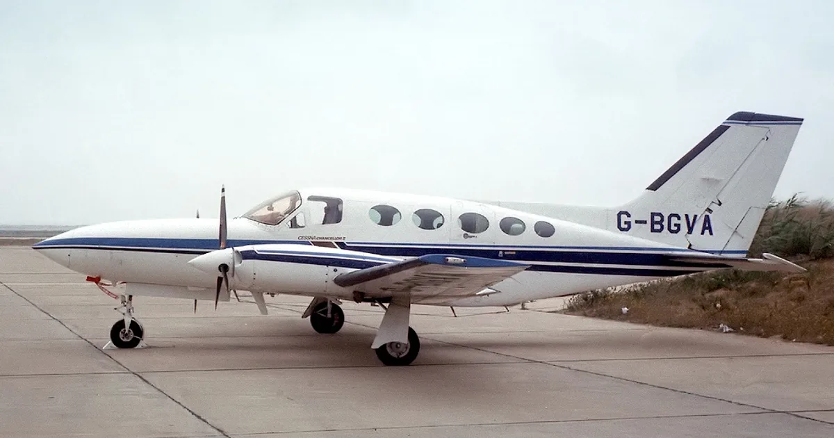


In this document
Regulatory Requirements and Definition of Terms
This section outlines the general regulatory framework governing airport design, including definitions of key terms and references to related reading materials. It emphasizes the importance of adhering to FAA standards in the planning and development of airport facilities.
Airport Geometry
This chapter discusses the geometric design of airports, including runway location, orientation, and the necessary separation standards for safe operations. It provides guidelines for designing taxiways and aprons to ensure efficient aircraft movement on the ground.
Runway Design
This section covers the critical aspects of runway design, including length, width, shoulders, and safety areas. It details the standards for runway protection zones and obstacle-free zones, which are essential for maintaining safety during takeoff and landing.
Taxiway and Taxilane Design
This chapter focuses on the design of taxiways and taxilanes, including dimensional standards, safety areas, and intersection design. It provides guidelines for ensuring safe and efficient ground movement of aircraft.
Site Requirements for NAVAID and ATC Facilities
This section outlines the requirements for siting navigational aids and air traffic control facilities at airports. It includes considerations for environmental assessments and the integration of these facilities into the overall airport layout.
Safety notes
- Ensure compliance with all FAA regulations during airport design and modification.
- Regularly review and update airport layout plans to reflect current standards.
Full document text
U.S. Department of Transportation Federal Aviation Administration AIRPORT DESIGN / INCORPORATES CHANGES 1 THRU 15 / AC: 150/5300-13 Date: 9/29/89 Advisory Circular 3/28/07 AC 150/5300-13 CHG 11 iii CONTENTS Paragraph Page Chapter 1. REGULATORY REQUIREMENTS AND DEFINITION OF TERMS 1. GENERAL .................................................................................................................................................................... 1 2. DEFINITIONS .............................................................................................................................................................. 1 3. RELATED/REFERENCED READING MATERIAL.................................................................................................. 3 4. AIRPORT REFERENCE CODE (ARC)....................................................................................................................... 5 5. AIRPORT LAYOUT PLAN ......................................................................................................................................... 5 6. MODIFICATION OF AIRPORT DESIGN STANDARDS TO MEET LOCAL CONDITIONS ............................... 5 7. NOTICE TO THE FAA OF AIRPORT DEVELOPMENT.......................................................................................... 5 8. NOTICE TO THE FAA OF PROPOSED CONSTRUCTION ..................................................................................... 6 9. FAA STUDIES.............................................................................................................................................................. 6 10. FEDERAL ASSISTANCE ............................................................................................................................................ 6 11. ENVIRONMENTAL ASSESSMENTS........................................................................................................................ 6 12. STATE ROLE ............................................................................................................................................................... 6 13. LOCAL ROLE .............................................................................................................................................................. 6 14. to 199. RESERVED ........................................................................................................................................................... 6 Chapter 2. AIRPORT GEOMETRY 200. INTRODUCTION ......................................................................................................................................................... 9 201. PRINCIPLES OF APPLICATION ............................................................................................................................... 9 202. RUNWAY LOCATION AND ORIENTATION .......................................................................................................... 9 203. ADDITIONAL RUNWAYS ........................................................................................................................................ 10 204. TAXIWAY SYSTEM .................................................................................................................................................. 10 205. AIRPORT APRONS .................................................................................................................................................... 10 206. SEPARATION STANDARDS .................................................................................................................................... 10 207. PARALLEL RUNWAY SEPARATION--SIMULTANEOUS VFR OPERATIONS................................................. 11 208. PARALLEL RUNWAY SEPARATION--SIMULTANEOUS IFR OPERATIONS .................................................. 11 209. RUNWAY TO PARALLEL TAXIWAY AND TAXILANE SEPARATION............................................................ 12 210. BUILDING RESTRICTION LINE (BRL) .................................................................................................................. 12 211. OBJECT CLEARING CRITERIA ............................................................................................................................... 12 212. RUNWAY PROTECTION ZONE (RPZ).................................................................................................................... 13 213. to 299. RESERVED ........................................................................................................................................................ 13 Chapter 3. RUNWAY DESIGN 300. INTRODUCTION ........................................................................................................................................................ 21 301. RUNWAY LENGTH ................................................................................................................................................... 21 302. RUNWAY WIDTH...................................................................................................................................................... 21 303. RUNWAY SHOULDERS............................................................................................................................................ 21 304. RUNWAY BLAST PAD.............................................................................................................................................. 21 305. RUNWAY SAFETY AREA (RSA)............................................................................................................................. 21 306. OBSTACLE FREE ZONE (OFZ) ................................................................................................................................ 22
Show full textShow less
307. RUNWAY OBJECT FREE AREA .............................................................................................................................. 23 308. CLEARWAY STANDARDS....................................................................................................................................... 23 309. STOPWAY STANDARDS.......................................................................................................................................... 23 310. RESCUE AND FIREFIGHTING ACCESS................................................................................................................. 24 311. to 399. RESERVED ........................................................................................................................................................ 24 Chapter 4. TAXIWAY AND TAXILANE DESIGN 400. INTRODUCTION ........................................................................................................................................................ 33 401. DIMENSIONAL STANDARDS ................................................................................................................................. 33 402. TAXIWAY SHOULDERS........................................................................................................................................... 33 403. TAXIWAY SAFETY AREA (TSA)............................................................................................................................ 33 404. TAXIWAY AND TAXILANE OBJECT FREE AREA (OFA) .................................................................................. 33 405. PARALLEL TAXIWAY.............................................................................................................................................. 33 406. TAXIWAY INTERSECTIONS ................................................................................................................................... 34 AC 150/5300-13 CHG 11 3/28/07 iv 407. ENTRANCE TAXIWAYS........................................................................................................................................... 34 408. BYPASS TAXIWAYS ................................................................................................................................................. 34 409. HOLDING BAYS......................................................................................................................................................... 34 410. TURNAROUNDS ........................................................................................................................................................ 34 411. DUAL PARALLEL TAXIWAYS................................................................................................................................ 34 412. TAXIWAY BETWEEN PARALLEL RUNWAYS..................................................................................................... 35 413. EXIT TAXIWAYS ....................................................................................................................................................... 35 414. APRON TAXIWAYS AND TAXILANES.................................................................................................................. 35 415. END-AROUND TAXIWAYS ......................................................................................................................................35 416. to 499. RESERVED......................................................................................................................................................... 38 Chapter 5. SURFACE GRADIENT AND LINE OF SIGHT 500. INTRODUCTION ........................................................................................................................................................ 49 501. BACKGROUND .......................................................................................................................................................... 49 502. SURFACE GRADIENT STANDARDS ...................................................................................................................... 49 503. LINE OF SIGHT STANDARDS.................................................................................................................................. 56 504. to 599. RESERVED......................................................................................................................................................... 56 Chapter 6. SITE REQUIREMENTS FOR NAVAID AND ATC FACILITIES 600. GENERAL.................................................................................................................................................................... 59 601. MICROWAVE LANDING SYSTEM ......................................................................................................................... 59 602. INSTRUMENT LANDING SYSTEM......................................................................................................................... 61 603. NONDIRECTIONAL BEACON.................................................................................................................................. 63 604. VERY HIGH FREQUENCY OMNIRANGE .............................................................................................................. 64 605. APPROACH LIGHTING SYSTEMS .......................................................................................................................... 64 606. OMNIDIRECTIONAL APPROACH LIGHTING SYSTEMS.................................................................................... 65 607. LEAD-IN LIGHTING SYSTEMS ............................................................................................................................... 65 608. AIRPORT ROTATING BEACONS ............................................................................................................................ 65 609. AIRPORT TRAFFIC CONTROL TOWERS............................................................................................................... 65 610. AIRPORT SURVEILLANCE RADAR ....................................................................................................................... 66 611. AIRPORT SURFACE DETECTION EQUIPMENT ................................................................................................... 66 612. RUNWAY VISUAL RANGE FACILITIES................................................................................................................ 66 613. AUTOMATIC WEATHER OBSERVATION STATIONS (AWOS) ......................................................................... 66 614. PHYSICAL SECURITY .............................................................................................................................................. 67 615. CABLE PROTECTION................................................................................................................................................ 67 616. to 699. RESERVED......................................................................................................................................................... 67 Chapter 7. RUNWAY AND TAXIWAY BRIDGES 700. INTRODUCTION ........................................................................................................................................................ 69 701. SITING PRECEPTS ..................................................................................................................................................... 69 702. DIMENSIONS.............................................................................................................................................................. 69 703. LOAD CONSIDERATIONS........................................................................................................................................ 69 704. DECK DESIGN............................................................................................................................................................ 69 705. MARKING AND LIGHTING...................................................................................................................................... 69 706. OTHER CONSIDERATIONS...................................................................................................................................... 69 707. PASSENGER AND BAGGAGE TUNNELS .............................................................................................................. 70 708. to 799. RESERVED......................................................................................................................................................... 70 Chapter 8. THE EFFECTS AND TREATMENT OF JET BLAST 800. INTRODUCTION ........................................................................................................................................................ 77 801. JET BLAST EFFECTS................................................................................................................................................. 77 802. BLAST FENCES .......................................................................................................................................................... 77 803. SHOULDERS AND BLAST PADS ............................................................................................................................ 78 3/28/07 AC 150/5300-13 CHG 11 v Appendix 1. WIND ANALYSIS 1. OBJECTIVE................................................................................................................................................................. 87 2. CROSSWINDS ............................................................................................................................................................ 87 3. COVERAGE AND ORIENTATION OF RUNWAYS ............................................................................................... 87 4. ASSEMBLING WIND DATA..................................................................................................................................... 87 5. ANALYZING WIND DATA....................................................................................................................................... 88 6. CONCLUSIONS .......................................................................................................................................................... 88 7. ASSUMPTIONS .......................................................................................................................................................... 88 8. COMPUTER WIND ANALYSIS................................................................................................................................ 88 Appendix 2. RUNWAY END SITING REQUIREMENTS 1. PURPOSE.................................................................................................................................................................... 100 2. APPLICATION ........................................................................................................................................................... 100 3. LIMITATIONS ........................................................................................................................................................... 100 4. EVALUATION CONSIDERATIONS........................................................................................................................ 100 5. CLEARANCE REQUIREMENTS ............................................................................................................................. 101 Appendix 3. AIRPORT REFERENCE POINT 1. DISCUSSION.............................................................................................................................................................. 109 2. SAMPLE COMPUTATION ....................................................................................................................................... 109 3. ACCURACY ............................................................................................................................................................... 109 Appendix 4. COMPASS CALIBRATION PAD 1. PURPOSE.................................................................................................................................................................... 111 2. BACKGROUND ......................................................................................................................................................... 111 3. APPLICATION ........................................................................................................................................................... 111 4. DESIGN OF COMPASS CALIBRATION PAD........................................................................................................ 111 5. LOCATION OF COMPASS CALIBRATION PAD .................................................................................................. 112 6. CONSTRUCTION OF COMPASS CALIBRATION PAD........................................................................................ 112 7. VOR CHECKPOINT .................................................................................................................................................. 113 Appendix 5. SMALL AIRPORT BUILDINGS, AIRPLANE PARKING, AND TIEDOWNS 1. GENERAL .................................................................................................................................................................. 117 2. TRANSIENT APRON ................................................................................................................................................ 117 3. APRON FOR BASED AIRPLANES.......................................................................................................................... 117 4. TIEDOWNS ................................................................................................................................................................ 118 5. OTHER CONSIDERATIONS .................................................................................................................................... 118 6. HANGARS.................................................................................................................................................................. 118 7. ADMINISTRATION BUILDING .............................................................................................................................. 118 8. AIRPORT SURVEY ................................................................................................................................................... 122 9. BUILDING PLAN ...................................................................................................................................................... 122 10. EXPANSION .............................................................................................................................................................. 122 11. CIRCULATION .......................................................................................................................................................... 122 12. WAITING ROOM....................................................................................................................................................... 122 13. MANAGER'S OFFICE ............................................................................................................................................... 123 14. EATING FACILITIES ................................................................................................................................................ 123 15. PUBLIC RESTROOMS .............................................................................................................................................. 123 16. ROADS AND AUTO PARKING ............................................................................................................................... 123 Appendix 6. METRIC CONVERSION AND TYPICAL AIRPORT LAYOUT PLAN Appendix cancelled (pp. 125-130) Appendix 7. AIRPORT LAYOUT PLAN COMPONENTS AND PREPARATION Appendix cancelled (pp. 131-138) AC 150/5300-13 CHG 11 3/28/07 vi Appendix 8. RUNWAY DESIGN RATIONALE 1. SEPARATIONS ..........................................................................................................................................................139 2. OBSTACLE FREE ZONE (OFZ) ...............................................................................................................................139 3. RUNWAY SAFETY AREA .......................................................................................................................................139 4. RUNWAY OBJECT FREE AREA (ROFA) ...............................................................................................................139 5. RUNWAY SHOULDERS AND BLAST PADS ........................................................................................................140 6. CLEARWAY...............................................................................................................................................................140 7. STOPWAY ..................................................................................................................................................................140 8. RUNWAY PROTECTION ZONE (RPZ) ...................................................................................................................140 Appendix 9. TAXIWAY AND TAXILANE DESIGN RATIONALE 1. INTRODUCTION .......................................................................................................................................................141 2. BACKGROUND AND RATIONALE........................................................................................................................141 3. EXIT TAXIWAY LOCATION...................................................................................................................................142 4. WINGTIP TRACE ......................................................................................................................................................146 Appendix 10. TAXIWAY FILLET DESIGN 1. INTRODUCTION .......................................................................................................................................................149 2. EXAMPLE NO. 1, JUDGMENTAL OVERSTEERING ............................................................................................150 3. EXAMPLE NO. 2, MAINTAINING COCKPIT OVER CENTERLINE ...................................................................150 Appendix 11. COMPUTER PROGRAM 1. AIRPORT DESIGN (FOR MICROCOMPUTERS) VERSION 4.2 ...........................................................................153 2. HOW TO OBTAIN A COPY OF AIRPORT DESIGN (FOR MICROCOMPUTERS) VERSION 4.2.....................153 3. REQUIREMENTS.......................................................................................................................................................153 4. SETUP ON A MICROCOMPUTER...........................................................................................................................153 5. RUN AIRPORT DESIGN PROGRAM.......................................................................................................................153 6. HOT KEYS..................................................................................................................................................................153 7. RUNWAY AND TAXIWAY WIDTH AND CLEARANCE STANDARD DIMENSIONS.....................................154 8. RECOMMENDED RUNWAY LENGTHS ................................................................................................................154 9. STANDARD WIND ANALYSIS ...............................................................................................................................154 10. TAXIWAY DESIGN...................................................................................................................................................155 11. AIRPORT CAPACITY AND DELAY FOR LONG RANGE PLANNING ..............................................................156 12. DECLARED DISTANCE LENGTHS ........................................................................................................................156 13. INPUT AIRPLANE DATA AVAILABILITY ...........................................................................................................156 Appendix 12. AIRPLANE DATA 1. BACKGROUND .........................................................................................................................................................165 2. EXPLANATORY INFORMATION ...........................................................................................................................166 Appendix 13. AIRPLANES ARRANGED BY AIRPLANEMANUFACTURER AND AIRPORT REFERENCE CODE Section 1. Alphabetical Listing (U.S. customary units)..........................................................................................................251 Section 2. Alphabetical Listing (SI units)...............................................................................................................................257 Section 3. Listing Small Airplanes by Airport Reference Code (U.S. customary units) ........................................................263 Section 4. Listing Large Airplanes by Airport Reference Code (U.S. customary units) ........................................................264 Section 5. Listing Small Airplanes by Airport Reference Code (SI units) .............................................................................269 Section 6. Listing Large Airplanes by Airport Reference Code (SI units) .............................................................................270 3/28/07 AC 150/5300-13 CHG 11 vii Appendix 14. DECLARED DISTANCES 1. APPLICATION ........................................................................................................................................................... 275 2. BACKGROUND ......................................................................................................................................................... 275 3. FAA APPROVAL FOR APPLYING DECLARED DISTANCES IN AIRPORT DESIGN...................................... 275 4. RUNWAY SAFETY AREA (RSA) AND RUNWAY OBJECT FREE AREA (ROFA) LENGTHS........................ 276 5. RUNWAY PROTECTION ZONE (RPZ) LOCATION AND SIZE .......................................................................... 276 6. CLEARWAY LOCATION ......................................................................................................................................... 276 7. NOTIFICATION ......................................................................................................................................................... 276 Appendix 15. TRANSFER OF ELECTRONIC DATA 1. INTRODUCTION ....................................................................................................................................................... 283 2. BACKGROUND ......................................................................................................................................................... 283 3. DEFINITIONS ............................................................................................................................................................ 283 4. APPLICATION ........................................................................................................................................................... 283 5. CADD FILE DELIVERABLES.................................................................................................................................. 284 6. DATABASES DELIVERABLES ............................................................................................................................... 286 7. PHOTOGRAMMETRY DELIVERABLES ............................................................................................................... 286 8. FEATURES AND OBJECTS CODE.......................................................................................................................... 287 9. MEDIA ........................................................................................................................................................................ 289 10. FAA POINT OF CONTACT ...................................................................................................................................... 289 Appendix 16. NEW INSTRUMENT APPROACH PROCEDURES 1. BACKGROUND ......................................................................................................................................................... 291 2. INTRODUCTION ....................................................................................................................................................... 291 3. ACTION ...................................................................................................................................................................... 291 4. DEFINITIONS ............................................................................................................................................................ 291 Appendix 17. MINIMUM DISTANCES BETWEEN CERTAIN AIRPORT FEATURES AND ANY ON-AIRPORT AGRICULTURE CROPS (1 page). Appendix 18. ACRONYMS (1 page). Appendix 19. INDEX (4 pages). AC 150/5300-13 CHG 11 3/28/07 viii Table Page 1-1. Increases in airport design standards associated with an upgrade in the first component (aircraft approach category) of the airport reference code............................................................ 7 1-2. Increases in airport design standards to provide for lower approach visibility minimums ......................................... 8 2-1. Runway separation standards for aircraft approach categories A & B....................................................................... 14 2-2. Runway separation standards for aircraft approach categories C & D....................................................................... 15 2-3. Taxiway and taxilane separation standards ................................................................................................................ 16 2-4. Runway protection zone (RPZ) dimensions ............................................................................................................... 19 3-1. Runway design standards for aircraft approach category A & B visual runways and runways with not lower than 3/4-statute mile (1 200 m) approach visibility minimums ..............................................................25 3-2. Runway design standards for aircraft approach categories A & B runways with lower than 3/4-statute mile (1 200 m) approach visibility minimums ................................................................... 26 3-3. Runway design standards for aircraft approach categories C & D......................................................................... 26-1 4-1. Taxiway dimensional standards.................................................................................................................................. 38 4-2. Taxiway fillet dimensions .......................................................................................................................................... 40 4-3. Wingtip clearance standards....................................................................................................................................... 40 4-4. Visual screen height calculation formula (same elevation as runway).................................................................... 48-5 4-5. Visual screen height calculation formula (EAT below DER elevation) for Design Group III................................ 48-6 4-6. Visual screen height calculation formula (EAT below DER elevation) for Design Group IV ............................... 48-7 4-7. Visual screen height calculation formula (EAT below DER elevation) for Design Groups V and VI ................... 48-8 4-8. Visual screen vertical height calculation tables....................................................................................................... 48-9 4-9. Visual screen panel wind-loading deflection allowance ....................................................................................... 48-12 4-10. CIE chromaticity coordinate limits........................................................................................................................ 48-12 4-11. Minimum reflection levels..................................................................................................................................... 48-13 A2-1. Approach/Departure Requirements Table .................................................................................................................103 A9-1. Exit taxiway cumulative utilization percentages .......................................................................................................142 A16-1A. Precision instrument approach requirements.............................................................................................................292 A16-1B Approach procedure with vertical guidance (APV-RNP) approach requirements....................................................293 A16-1C Nonprecision approach requirements ........................................................................................................................294 A16-2 Survey requirements for instrument approach procedures ........................................................................................295 A17-1. Minimum Distances Between Certain Airport Features and Any On-Airport Agriculture Crops ............................296 Figure Page 2-1. Typical airport layout ................................................................................................................................................. 17 2-2. Parallel runway separation.......................................................................................................................................... 18 2-3. Runway protection zone ............................................................................................................................................. 20 3-1. Runway safety area..................................................................................................................................................... 27 3-2. Obstacle free zone (OFZ) for visual runways and runways with not lower than 3/4 statute mile (1 200 m) approach visibility minimums........................................................................................................................................ 28 3-3. Obstacle free zone (OFZ) for runways serving small airplanes exclusively with lower than 3/4-statute mile (1 200 m) approach visibility minimums ..................................................................................... 29 3-4. Obstacle free zone (OFZ) for runways serving large airplanes with lower than 3/4-statute mile (1 200 m) approach visibility minimums................................................................................................................................ 30 3-5. Obstacle free zone (OFZ) for runways serving large airplanes with lower than 3/4-statute mile (1 200 m) approach visibility minimums and displaced threshold ......................................................................................... 31 3-6. Precision object free zone............................................................................................................................................32 3-7. Clearway................................................................................................................................................................. 32-1 3-8. Stopway .................................................................................................................................................................. 32-2 4-1. Taxiway intersection details ....................................................................................................................................... 39 4-2. Maintaining cockpit over centerline ........................................................................................................................... 41 4-3. Judgmental oversteering ............................................................................................................................................. 42 4-4. Example of pavement fillet computer program printout............................................................................................. 43 4-5. Entrance taxiway ........................................................................................................................................................ 44 4-6. Bypass taxiway........................................................................................................................................................... 44 4-7. Dual parallel taxiway entrance ................................................................................................................................... 45 4-8. Typical holding bay configurations............................................................................................................................ 46 3/28/07 AC 150/5300-13 CHG 11 ix 4-9. Taxiway turnaround ................................................................................................................................................... 46 4-10. Crossover taxiway...................................................................................................................................................... 47 4-11. Right-angled exit taxiway .......................................................................................................................................... 47 4-12. Acute-angled exit taxiway.......................................................................................................................................... 48 4-13. Example of acute-angled exit taxiway computer layout data page 1 ...................................................................... 48-1 4-14. Example of acute-angled exit taxiway computer layout data page 2 ...................................................................... 48-2 4-15. Typical end-around taxiway layout..........................................................................................................................48-3 4-16. End-around taxiway visual screen width calculations..............................................................................................48-4 4-17. Visual screen width calculation formula ..................................................................................................................48-5 4-18. Examples of mounting screen to vertical column ..................................................................................................48-10 4-19. Examples of panel layout for 13-foot-high screen .................................................................................................48-11 4-20. Diagonal stripe orientation .....................................................................................................................................48-12 4-21. Examples of frangibility connections.....................................................................................................................48-14 5-1. Longitudinal grade limitations for aircraft approach categories A & B..................................................................... 50 5-2. Transverse grade limitations for aircraft approach categories A & B........................................................................ 51 5-3. Longitudinal grade limitations for aircraft approach categories C & D..................................................................... 52 5-4. Transverse grade limitations for aircraft approach categories C & D........................................................................ 53 5-5. Runway safety area grade limitations beyond 200 feet (60 m) from the runway end................................................ 55 5-6. Runway visibility zone............................................................................................................................................... 57 6-1. AZ antenna siting ....................................................................................................................................................... 59 6-2. Typical NAVAID placement...................................................................................................................................... 60 6-3. AZ antenna critical area ............................................................................................................................................. 61 6-4. EL antenna siting........................................................................................................................................................ 61 6-5. EL antenna critical area.............................................................................................................................................. 61 6-6. ILS LOC siting and critical area................................................................................................................................. 62 6-7. GS siting and critical area .......................................................................................................................................... 62 6-8. Marker beacon site ..................................................................................................................................................... 63 6-9. NDB site..................................................................................................................................................................... 63 6-10. A TVOR installation .................................................................................................................................................. 64 7-1. Full width runway-taxiway bridge ............................................................................................................................. 71 7-2. Cross-section full width runway-taxiway bridge ....................................................................................................... 72 7-3. Minimum width taxiway bridge with positive edge protection, O'Hare Airport, Chicago, IL.................................. 73 7-4. Example structural deck and depressed roadway, O'Hare Airport, Chicago, IL........................................................ 74 7-5. Suggested shoulder marking of minimum width taxiway bridge............................................................................... 75 7-6. Controlled use service road, Los Angeles International Airport, Los Angeles, CA ................................................. 76 8-1. Velocity distance curves, DC-8.................................................................................................................................. 79 8-2. Velocity distance curves, B-727................................................................................................................................. 80 8-3. Velocity distance curves, B-747................................................................................................................................. 81 8-4. Velocity distance curves, DC-10................................................................................................................................ 82 8-5. Blast velocities of business jet airplanes .................................................................................................................... 83 8-6. Typical blast deflector fences, metal .......................................................................................................................... 84 8-7. Typical blast deflector fences, concrete ..................................................................................................................... 85 A1-1. Wind vector diagram.................................................................................................................................................. 89 A1-2. Typical environmental data service wind summary ................................................................................................... 90 A1-3. Windrose blank showing direction and divisions ...................................................................................................... 91 A1-4. Completed windrose using figure A1-2 data.............................................................................................................. 92 A1-5. Windrose analysis ...................................................................................................................................................... 93 A1-6. Windrose analysis--estimating area not included....................................................................................................... 94 A1-7. Computer printout page 1........................................................................................................................................... 95 A1-8. Computer printout page 2........................................................................................................................................... 96 A1-9. Computer printout page 3........................................................................................................................................... 97 A1-10. Lotus cell-formulas page 1......................................................................................................................................... 98 A1-11. Lotus cell-formulas page 2......................................................................................................................................... 99 A2-1. Approach slopes ........................................................................................................................................................ 105 A2-2. Approach slopes—with offset approach course........................................................................................................ 106 A2-3. Departure surface for Instrument Runways TERPS (40:1)....................................................................................... 107 A2-4. One-Engine Inoperative (OEI) Obstacle Identification Surface (62.5:1).................................................................. 108 A3-1. Sample layout............................................................................................................................................................ 109 AC 150/5300-13 CHG 11 3/28/07 x A3-2. Sample computation - airport reference point ...........................................................................................................110 A4-1. Marking layout and details of wheel block ...............................................................................................................114 A4-2. Type I. compass calibration pad ................................................................................................................................115 A4-3. Type II. compass calibration pad...............................................................................................................................116 A5-1. Parking apron area.....................................................................................................................................................119 A5-2. Tiedown layouts ........................................................................................................................................................120 A5-3. T-hanger layout .........................................................................................................................................................121 A8-1. Approximate distance airplanes undershoot and overrun the runway end ................................................................140 A9-1. Wingtip clearance - parallel taxiways........................................................................................................................143 A9-2. Wingtip clearance from taxiway................................................................................................................................144 A9-3. Wingtip clearance from apron taxiway .....................................................................................................................144 A9-4. Wingtip clearance from taxilane................................................................................................................................145 A9-5. Pavement edge clearance on tangent .........................................................................................................................146 A9-6. McDonnell-Douglas MD-88 wingtip clearance trace for a 100-foot (30.5 m) radius centerline ..............................147 A9-7. McDonnell-Douglas MD-88 wingtip clearance trace for a 120-foot (36.5 m) radius offset centerline ....................147 A9-8. Boeing 727-200 wingtip clearance trace for a 120-foot (36.5 m) radius offset centerline........................................148 A9-9. Boeing 727-100 wingtip clearance trace for a 120-foot (36.5 m) radius offset centerline........................................148 A10-1. Taxiway intersection details ......................................................................................................................................151 A10-2. Depiction of symbols.................................................................................................................................................152 A11-1. THIS FIGURE INTENTIONALLY LEFT BLANK ................................................................................................156 A11-2. Estimated airplane data elements for input in the computer program .......................................................................157 A11-3. Example of the airport design airplane and airport data window ..............................................................................158 A11-4. Example printout of width and clearance standard dimensions page 1 .....................................................................158 A11-5. Example printout of width and clearance standard dimensions page 2 .....................................................................159 A11-6. Example printout of wind analysis (two bi-directional runways)..............................................................................160 A11-7. Example printout of windrose (two bi-directional runways).....................................................................................161 A11-8. Example printout of wind analysis (one uni-directional runway) .............................................................................162 A11-9. Example printout of windrose (one uni-directional runway) ....................................................................................163 A11-10. Nomenclature used in the taxiway design task..........................................................................................................164 A11-11. Nomenclature used in the declared distance task ......................................................................................................164 A12-1. Single engine, high wing, tailwheel airplanes 8,000 lb. (3,628 Kg) or less ..............................................................167 A12-2. Single engine, high wing, tailwheel airplanes 8,000 lb. (3,628 Kg) or less (cont'd) .................................................168 A12-3. Single engine, high wing, tricycle gear airplanes 8,000 lb. (3,628 Kg) or less .........................................................169 A12-4. Single engine, low wing, tricycle gear airplanes 8,000 lb. (3,628 Kg) or less ..........................................................170 A12-5. Single engine, low wing, tricycle gear airplanes 8,000 lb. (3,628 Kg) or less (cont'd) .............................................171 A12-6. Twin engine, low or mid wing, tricycle gear airplanes 8,000 lb. (3,628 Kg) or less ................................................172 A12-7. Twin engine, low or mid wing, tricycle gear airplanes 8,000 lb. (3,628 Kg) or less (cont'd) ...................................173 A12-8. Twin engine, high or mid wing, tricycle gear airplanes 8,000 lb. (3,628 Kg) or less ...............................................174 A12-9. Aérospatiale Nord 262...............................................................................................................................................175 A12-10. Aérospatiale/Sud SE-210 Caravelle ..........................................................................................................................176 A12-11. Airbus Industries A300, 310, and 320.......................................................................................................................177 A12-12. Avions de Transport Regional ATR-42 & -72 ..........................................................................................................178 A12-13. Avions Marcel Dassault Mystère 20 (Fan Jet Falcon)...............................................................................................179 A12-14. BAe 1-11 ...................................................................................................................................................................180 A12-15. B.A.C./SNIAS Concorde...........................................................................................................................................181 A12-16. B.A.C./Vickers VC-10 ..............................................................................................................................................182 A12-17. B.A.C./Vickers Viscount...........................................................................................................................................183 A12-18. Beech Starship ...........................................................................................................................................................184 A12-19. Beechcraft Airliner ....................................................................................................................................................185 A12-20. Beechcraft King Air ..................................................................................................................................................186 A12-21. Beechcraft Model 18 and Conversions......................................................................................................................187 A12-22. Beechcraft Queen Air ................................................................................................................................................188 A12-23. Boeing B-52 Stratofortress ........................................................................................................................................189 A12-24. Boeing KC-97L .........................................................................................................................................................190 A12-25. Boeing KC-135A.......................................................................................................................................................191 A12-26. Boeing 707-720 .........................................................................................................................................................192 A12-27. Boeing 727 ................................................................................................................................................................193 A12-28. Boeing 737 ................................................................................................................................................................194 3/28/07 AC 150/5300-13 CHG 11 xi A12-29. Boeing 747 ................................................................................................................................................................ 195 A12-30. Boeing 757 ................................................................................................................................................................ 196 A12-31. Boeing 767 ................................................................................................................................................................ 197 A12-32. British Aerospace 146 ............................................................................................................................................... 198 A12-33. Canadiar CL-44......................................................................................................................................................... 199 A12-34. Canadiar CL-66......................................................................................................................................................... 200 A12-35. Cessna Citation.......................................................................................................................................................... 201 A12-36. Construcciones Aeronauticas CASA C-212 and 235................................................................................................ 202 A12-37. Convair-liner and Turboprop Conversions ............................................................................................................... 203 A12-38. De Havilland Canada C-7 Caribou............................................................................................................................ 204 A12-39. De Havilland Canada DASH 7 & DASH 8............................................................................................................... 205 A12-40. Douglas C-124 Globemaster ..................................................................................................................................... 206 A12-41. De Havilland Canada DHC-6 Twin Otter ................................................................................................................. 207 A12-42. Dornier Gmb H ......................................................................................................................................................... 208 A12-43. Douglas DC-3............................................................................................................................................................ 209 A12-44. Douglas DC-4/6/7 ..................................................................................................................................................... 210 A12-45. Embraer EmB 110..................................................................................................................................................... 211 A12-46. Embraer EmB 120..................................................................................................................................................... 212 A12-47. Fairchild C-119K Flying Boxcar............................................................................................................................... 213 A12-48. Fairchild C-123K Provider........................................................................................................................................ 214 A12-49. Fairchild F-27............................................................................................................................................................ 215 A12-50. Fokker F-27............................................................................................................................................................... 216 A12-51. Fokker F-28............................................................................................................................................................... 217 A12-52. Gates Learjet ............................................................................................................................................................. 218 A12-53. General Dynamics/Convair 880/990 ......................................................................................................................... 219 A12-54. Grumman Gulfstream I ............................................................................................................................................. 220 A12-55. Grumman Gulfstream II ............................................................................................................................................ 221 A12-56. Grumman G-64/G-III ................................................................................................................................................ 222 A12-57. Grumman G-73 ......................................................................................................................................................... 223 A12-58. Hamburger-Flugzeubau HFB-320 Hansa.................................................................................................................. 224 A12-59. Hawker Siddeley DH. 104 Dove............................................................................................................................... 225 A12-60. Hawker Siddeley DH. 114 Heron ............................................................................................................................. 226 A12-61. Hawker Siddeley HS-125.......................................................................................................................................... 227 A12-62. Hawker Siddeley HS-748.......................................................................................................................................... 228 A12-63. Ilyushin IL-62............................................................................................................................................................ 229 A12-64. Israel Aircraft Industries Westwind .......................................................................................................................... 230 A12-65. Lockheed Constellation and Super Constellation ..................................................................................................... 231 A12-66. Lockheed C-5B Galaxy............................................................................................................................................. 232 A12-67. Lockheed C-141 Starlifter......................................................................................................................................... 233 A12-68. Lockheed L-188 Electra II ........................................................................................................................................ 234 A12-69. Lockheed L-100 Hercules ......................................................................................................................................... 235 A12-70. Lockheed L-1011 Tristar........................................................................................................................................... 236 A12-71. Lockheed L-1329 Jetstar ........................................................................................................................................... 237 A12-72. Martin 404................................................................................................................................................................. 238 A12-73. McDonnell-Douglas DC-8 ........................................................................................................................................ 239 A12-74. McDonnell-Douglas DC-9 and MD-80..................................................................................................................... 240 A12-75. McDonnell-Douglas DC-10 ...................................................................................................................................... 241 A12-76. McDonnell-Douglas MD-11 ..................................................................................................................................... 242 A12-77. Mitsubishi MU-2 ....................................................................................................................................................... 243 A12-78. Nihon/N.A.M.C. YS-11A ......................................................................................................................................... 244 A12-79. Rockwell International NA-265 Sabreliner............................................................................................................... 245 A12-80. SAAB SF 340............................................................................................................................................................ 246 A12-81. Short Brothers ........................................................................................................................................................... 247 A12-82. Shorts SC. 5/10 Belfast ............................................................................................................................................. 248 A12-83. Swearingen Merlin .................................................................................................................................................... 249 A12-84. Swearingen Metro ..................................................................................................................................................... 250 A14-1. Takeoff run available (TORA).................................................................................................................................. 277 A14-2. Takeoff distance available (TODA) .......................................................................................................................... 278 AC 150/5300-13 CHG 11 3/28/07 xii A14-3. Accelerate-stop distance available (ASDA) ..............................................................................................................279 A14-4. Landing distance available (LDA) ............................................................................................................................280 A14-5. Example of a runway extended to 7000 feet .............................................................................................................281 A14-6. Example of a runway with threshold displaced for runway safety area ....................................................................282 1/3/08 AC 150/5300-13 CHG 12 Chap 1 1 Chapter 1. REGULATORY REQUIREMENTS AND DEFINITION OF TERMS 1. GENERAL. Section 103 of the Federal Aviation Act of 1958 states in part, “In the exercise and performance of his power and duties under this Act, the Secretary of Transportation shall consider the following, among other things, as being in the public interest: (a) The regulation of air commerce in such manner as to best promote its development and safety and fulfill the requirements of defense; (b) The promotion, encouragement, and development of civil aeronautics . . . .” This public charge, in effect, requires the development and maintenance of a national system of safe, delay-free, and cost-effective airports. The use of the standards and recommendations contained in this publication in the design of airports supports this public charge. These standards and recommendations, however, do not limit or regulate the operations of aircraft. 2. DEFINITIONS. As used in this publication, the following terms mean: Aircraft Approach Category. A grouping of aircraft based on 1.3 times their stall speed in their landing configuration at the certificated maximum flap setting and maximum landing weight at standard atmospheric conditions. The categories are as follows: Category A: Speed less than 91 knots. Category B: Speed 91 knots or more but less than 121 knots. Category C: Speed 121 knots or more but less than 141 knots. Category D: Speed 141 knots or more but less than 166 knots. Category E: Speed 166 knots or more. Airplane Design Group (ADG). A grouping of airplanes based on wingspan or tail height. Where an airplane is in two categories, the most demanding category should be used. The groups are as follows: Group I: Up to but not including 49 feet (15 m) wingspan or tail height up to but not including 20 feet. Group II: 49 feet (15 m) up to but not including 79 feet (24 m) wingspan or tail height from 20 up to but not including 30 feet. Group III: 79 feet (24 m) up to but not including 118 feet (36 m) wingspan or tail height from 30 up to but not including 45 feet. Group IV: 118 feet (36 m) up to but not including 171 feet (52 m) wingspan or tail height from 45 up to but not including 60 feet. Group V: 171 feet (52 m) up to but not including 214 feet (65 m) wingspan or tail height from 60 up to but not including 66 feet. Group VI: 214 feet (65 m) up to but not including 262 feet (80 m) wingspan or tail height from 66 up to but not including 80 feet. Table 1-1. Airplane Design Groups (ADG) Group # Tail Height (ft) Wingspan (ft) I <20 <49 II 20 - <30 49 - <79 III 30 - <45 79 - <118 IV 45 - <60 118 - <171 V 60 - <66 171 - <214 VI 66 - <80 214 - <262 Airport Elevation. The highest point on an airport's usable runway expressed in feet above mean sea level (MSL). Airport Layout Plan (ALP). The plan of an airport showing the layout of existing and proposed airport facilities. Airport Reference Point (ARP). The latitude and longitude of the approximate center of the airport. Blast Fence. A barrier used to divert or dissipate jet blast or propeller wash. Building Restriction Line (BRL). A line which identifies suitable building area locations on airports. Clear Zone. See Runway Protection Zone. Clearway (CWY). A defined rectangular area beyond the end of a runway cleared or suitable for use in lieu of runway to satisfy takeoff distance requirements. Compass Calibration Pad. An airport facility used for calibrating an aircraft compass. AC 150/5300-13 CHG 10 9/29/06 Chap 1 2 Declared Distances. The distances the airport owner declares available for the airplane's takeoff run, takeoff distance, accelerate-stop distance, and landing distance requirements. The distances are: Takeoff run available (TORA). The runway length declared available and suitable for the ground run of an airplane taking off; Takeoff distance available (TODA). The TORA plus the length of any remaining runway or clearway (CWY) beyond the far end of the TORA; NOTE: The full length of TODA may not be usable for all takeoffs because of obstacles in the departure area. The usable TODA length is aircraft performance dependent and, as such, must be determined by the aircraft operator before each takeoff and requires knowledge of the location of each controlling obstacle in the departure area. Accelerate-stop distance available (ASDA). The runway plus stopway (SWY) length declared available and suitable for the acceleration and deceleration of an airplane aborting a takeoff; and Landing distance available (LDA). The runway length declared available and suitable for a landing airplane. Fixed By Function NAVAID. An air navigation aid (NAVAID) that must be positioned in a particular location in order to provide an essential benefit for civil aviation is fixed by function. Exceptions are: a. Equipment shelters, junction boxes, transformers, and other appurtenances that support a fixed by function NAVAID are not fixed by function unless operational requirements require them to be located in close proximity to the NAVAID. b. Some NAVAIDs, such as localizers, can provide beneficial performance even when they are not located at their optimal location. These NAVAIDS are not fixed by function. Frangible NAVAID. A navigational aid (NAVAID) which retains its structural integrity and stiffness up to a designated maximum load, but on impact from a greater load, breaks, distorts, or yields in such a manner as to present the minimum hazard to aircraft. The term NAVAID includes electrical and visual air navigational aids, lights, signs, and associated supporting equipment. Hazard to Air Navigation. An object which, as a result of an aeronautical study, the FAA determines will have a substantial adverse effect upon the safe and efficient use of navigable airspace by aircraft, operation of air navigation facilities, or existing or potential airport capacity. Large Airplane. An airplane of more than 12,500 pounds (5 700 kg) maximum certificated takeoff weight. Low Impact Resistant Supports (LIRS). Supports designed to resist operational and environmental static loads and fail when subjected to a shock load such as that from a colliding aircraft. Object. Includes, but is not limited to above ground structures, NAVAIDs, people, equipment, vehicles, natural growth, terrain, and parked aircraft. Object Free Area (OFA). An area on the ground centered on a runway, taxiway, or taxilane centerline provided to enhance the safety of aircraft operations by having the area free of objects, except for objects that need to be located in the OFA for air navigation or aircraft ground maneuvering purposes. Obstacle Clearance Surface (OCS). An inclined obstacle evaluation surface associated with a glidepath. The separation between this surface and the glidepath angle at any given distance from GPI defines the MINIMUM required obstruction clearance at that point. Obstacle Free Zone (OFZ). The OFZ is the airspace below 150 feet (45 m) above the established airport elevation and along the runway and extended runway centerline that is required to be clear of all objects, except for frangible visual NAVAIDs that need to be located in the OFZ because of their function, in order to provide clearance protection for aircraft landing or taking off from the runway, and for missed approaches. The OFZ is sub-divided as follows: Runway OFZ. The airspace above a surface centered on the runway centerline. Inner-approach OFZ. The airspace above a surface centered on the extended runway centerline. It applies to runways with an approach lighting system. Inner-transitional OFZ. The airspace above the surfaces located on the outer edges of the runway OFZ and the inner-approach OFZ. It applies to runways with approach visibility minimums lower than 3/4-statute mile (1 200 m). Obstruction to Air Navigation. An object of greater height than any of the heights or surfaces presented in Subpart C of Code of Federal Regulation (14 CFR), Part 77. (Obstructions to air navigation are presumed to be hazards to air navigation until an FAA study has determined otherwise.) Precision Approach Category I (CAT I) Runway. A runway with an instrument approach procedure which provides for approaches to a decision height (DH) of not less than 200 feet (60 m) and visibility of not less than 1/2 mile (800 m) or Runway Visual Range (RVR) 2400 (RVR 1800 with operative touchdown zone and runway centerline lights). 1/3/08 AC 150/5300-13 CHG 12 Chap 1 3 Precision Approach Category II (CAT II) Runway. A runway with an instrument approach procedure which provides for approaches to a minima less than CAT I to as low as a decision height (DH) of not less than 100 feet (30 m) and RVR of not less than RVR 1200. Precision Approach Category III (CAT III) Runway. A runway with an instrument approach procedure which provides for approaches to minima less than CAT II. Runway (RW). A defined rectangular surface on an airport prepared or suitable for the landing or takeoff of airplanes. Runway Blast Pad. A surface adjacent to the ends of runways provided to reduce the erosive effect of jet blast and propeller wash. Runway Protection Zone (RPZ). An area off the runway end to enhance the protection of people and property on the ground. Runway Safety Area (RSA). A defined surface surrounding the runway prepared or suitable for reducing the risk of damage to airplanes in the event of an undershoot, overshoot, or excursion from the runway. Shoulder. An area adjacent to the edge of paved runways, taxiways, or aprons providing a transition between the pavement and the adjacent surface; support for aircraft running off the pavement; enhanced drainage; and blast protection. Small Airplane. An airplane of 12,500 pounds (5 700 kg) or less maximum certificated takeoff weight. Stopway (SWY). A defined rectangular surface beyond the end of a runway prepared or suitable for use in lieu of runway to support an airplane, without causing structural damage to the airplane, during an aborted takeoff. Taxilane (TL). The portion of the aircraft parking area used for access between taxiways and aircraft parking positions. Taxiway (TW). A defined path established for the taxiing of aircraft from one part of an airport to another. Taxiway Safety Area (TSA). A defined surface alongside the taxiway prepared or suitable for reducing the risk of damage to an airplane unintentionally departing the taxiway. Threshold (TH). The beginning of that portion of the runway available for landing. In some instances, the landing threshold may be displaced. Displaced Threshold. A threshold that is located at a point on the runway other than the designated beginning of the runway. Visual Runway. A runway without an existing or planned straight-in instrument approach procedure. 3. RELATED/REFERENCED READING MATERIAL. The following is a listing of documents referenced in other parts of this advisory circular. Advisory Circulars 00-2 and 00-44 may be obtained by writing to: The U.S. Department of Transportation; Utilization and Storage Section, M-443.2; Washington, D.C. 20590. The most current versions of the ACs listed below are available online at www.faa.gov. NOTE: Some of the ACs in this paragraph have been cancelled but are still referenced in the main document. They will continue to be listed here and shown as cancelled until the next complete revision of the document. a. AC 00-2, Advisory Circular Checklist. b. AC 00-44, Status of Federal Aviation Regulations. c. AC 20-35, Tiedown Sense. d. AC 70/7460-1, Obstruction Marking and Lighting. e. AC 70/7460-2, Proposed Construction or Alteration of Objects that May Affect the Navigable Airspace. (Cancelled) f. AC 107-1, Aviation Security-Airports. g. AC 120-29, Criteria for Approving Category I and Category II Landing Minima for FAR Part 121 Operators. h. AC 150/5000-3, Address List for Regional Airports Divisions and Airports District/Field Offices. (Cancelled) i. AC 150/5060-5, Airport Capacity and Delay. j. AC 150/5070-3, Planning the Airport Industrial Park. (Cancelled) k. AC 150/5070-6, Airport Master Plans. l. AC 150/5190-1, Minimum Standards for Commercial Aeronautical Activities on Public Airports. (Cancelled by AC 150/5190-5) AC 150/5300-13 CHG 12 1/3/08 Chap 1 4 m. AC 150/5190-4, A Model Zoning Ordinance to Limit Height of Objects Around Airports. n. AC 150/5190-5, Exclusive Rights and Minimum Standards for Commercial Aeronautical Activities. (Cancelled by AC 150/5190-6 and AC 150/5190-7) o. AC 150/5190-6, Exclusive Rights at Federally-Obligated Airports p. AC 150/5190-7, Minimum Standards for Commercial Aeronautical Activities q. AC 150/5200-33, Hazardous Wildlife Attractants On or Near Airports. r. AC 150/5220-16, Automated Weather Observing Systems (AWOS) for Non-Federal Applications. s. AC 150/5230-4, Aircraft Fuel Storage, Handling, and Dispensing on Airports. t. AC 150/5320-5, Airport Drainage. u. AC 150/5320-6, Airport Pavement Design and Evaluation. v. AC 150/5320-14, Airport Landscaping for Noise Control Purposes. w. AC 150/5325-4, Runway Length Requirements for Airport Design. x. AC 150/5340-1, Standards for Airport Marking. y. AC 150/5340-5, Segmented Circle Marker Systems. z. AC 150/5340-14, Economy Approach Lighting Aids. (Cancelled by AC 150/5340-30) aa. AC 150/5340-18, Standards for Airport Sign Systems. bb. AC 150/5340-21, Airport Miscellaneous Lighting Visual Aids. (Cancelled by AC 150/5340-30) cc. AC 150/5340-24, Runway and Taxiway Edge Lighting System. (Cancelled by AC 150/5340-30) dd. AC 150/5340-28, Precision Approach Path Indicator (PAPI) Systems. (Cancelled by AC 150/5340-30) ee. AC 150/5340-30, Design and Installation Details for Airport Visual Aids ff. AC 150/5345-52, Generic Visual Slope Indicators (GVGI). gg. AC 150/5360-13, Planning and Design Guidelines for Airport Terminal Facilities. hh. AC 150/5370-10, Standards for Specifying Construction of Airports. ii. AC 150/5390-2, Heliport Design. jj. 14 CFR Part 23, Airworthiness Standards: Normal, Utility, Acrobatic, and Commuter Category Airplanes. kk. 14 CFR Part 25, Airworthiness Standards: Transport Category Airplanes. ll. 14 CFR Part 77, Objects Affecting Navigable Airspace. mm. 14 CFR Part 97, Standard Instrument Approach Procedures. nn. 14 CFR Part 135, Operating Requirements: Commuter and On Demand Operations and Rules Governing Persons On Board Such Aircraft. oo. 14 CFR Part 139, Certification of Airports. pp. 14 CFR Part 151, Federal Aid to Airports. qq. 14 CFR Part 152, Airport Aid Program. rr. 14 CFR Part 153, Acquisition of U.S. Land for Public Airports. (Removed from Title 14) ss. 14 CFR Part 154, Acquisition of Land for Public Airports Under the Airport and Airway Development Act of 1970. (Removed from Title 14) tt. 14 CFR Part 157, Notice of Construction, Alteration, Activation, and Deactivation of Airports. uu. Order 1050.1, Policies and Procedures for Considering Environmental Impacts. vv. Order 5050.4, Airport Environmental Handbook. ww. Order 5100.38, Airport Improvement Program (AIP) Handbook. xx. Order 7400.2, Procedures for Handling Airspace Matters. yy. Order 8200.1, United States Standard Flight Inspection Manual. zz. Order 8260.3, United States Standard for Terminal Instrument Procedures (TERPS). 9/29/06 AC 150/5300-13 CHG 10 Chap 1 5 4. AIRPORT REFERENCE CODE (ARC). The ARC is a coding system used to relate airport design criteria to the operational and physical characteristics of the airplanes intended to operate at the airport. a. Coding System. The airport reference code has two components relating to the airport design aircraft. The first component, depicted by a letter, is the aircraft approach category and relates to aircraft approach speed (operational characteristic). The second component, depicted by a Roman numeral, is the airplane design group and relates to airplane wingspan or tailheight (physical characteristics), whichever is the most restrictive. Generally, runways standards are related to aircraft approach speed, airplane wingspan, and designated or planned approach visibility minimums. Taxiway and taxilane standards are related to airplane design group. b. Airport Design. Airport design first requires selecting the ARC(s), then the lowest designated or planned approach visibility minimums for each runway, and then applying the airport design criteria associated with the airport reference code and the designated or planned approach visibility minimums. (1) An upgrade in the first component of the ARC may result in an increase in airport design standards. Table 1-1 depicts these increases. (2) An upgrade in the second component of the ARC generally will result in a major increase in airport design standards. (3) An airport upgrade to provide for lower approach visibility minimums may result in an increase in airport design standards. Table 1-2 depicts these increases. (4) Operational minimums are based on current criteria, runways, airspace, and instrumentation. Unless this is taken into consideration in the development of the airport, the operational minimums may be other than proposed. (5) For airports with two or more runways, it may be desirable to design all airport elements to meet the requirements of the most demanding ARC. However, it may be more practical to design some airport elements, e.g., a secondary runway and its associated taxiway, to standards associated with a lesser demanding ARC. 5. AIRPORT LAYOUT PLAN. An Airport Layout Plan (ALP) is a scaled drawing of existing and proposed land and facilities necessary for the operation and development of the airport. Any airport will benefit from a carefully developed plan that reflects current FAA design standards and planning criteria. For guidance on developing Airport Master Plans, refer to AC 150/5070-6, Airport Master Plans. a. FAA-Approved ALP. All airport development carried out at Federally obligated airports must be done in accordance with an FAA-approved ALP. The FAA-approved ALP, to the extent practicable, should conform to the FAA airport design standards existing at the time of its approval. Due to unique site, environmental, or other constraints, the FAA may approve an ALP not fully complying with design standards. Such approval requires an FAA study and finding that the proposed modification is safe for the specific site and conditions. When the FAA upgrades a standard, airport owners should, to the extent practicable, include the upgrade in the ALP before starting future development. b. Guidance. AC 150/5070-6, Airport Master Plans, contains background information on the development of ALPs, as well as a detailed listing of the various components that constitute a well-appointed ALP. c. Electronic Plans. The FAA recommends the development of electronic ALPs where practical. 6. MODIFICATION OF AIRPORT DESIGN STANDARDS TO MEET LOCAL CONDITIONS. “Modification to standards” means any change to FAA design standards other than dimensional standards for runway safety areas. Unique local conditions may require modification to airport design standards for a specific airport. A modification to an airport design standard related to new construction, reconstruction, expansion, or upgrade on an airport which received Federal aid requires FAA approval. The request for modification should show that the modification will provide an acceptable level of safety, economy, durability, and workmanship. Appendixes 8 and 9 discuss the relationship between airplane physical characteristics and the design of airport elements. This rationale along with the computer program cited in appendix 11 may be used to show that the modification will provide an acceptable level of safety for the specified conditions, including the type of aircraft. 7. NOTICE TO THE FAA OF AIRPORT DEVELOPMENT. 14 CFR Part 157, Notice of Construction, Activation, and Deactivation of Airports, requires persons proposing to construct, activate, or deactivate an airport to give notice of their intent to the FAA. The notice applies to proposed alterations to the takeoff and landing areas, traffic patterns, and airport use, e.g., a change from private-use to public-use. a. Notice Procedure. 14 CFR Part 157 requires airport proponents to notify the appropriate FAA Airports Regional or District Office at least 30 days before construction, alteration, deactivation, or the date of the proposed change in use. In an emergency involving essential public service, health, or safety, or when delay would result in a hardship, a proponent may notify the FAA by telephone and submit Form 7480-1, Notice of Landing Area Proposal, within 5 days. b. The Notice. The notice consists of a completed FAA Form 7480-1, a layout sketch, and a location map. The layout sketch should show the airport takeoff and landing area configuration in relation to buildings, trees, fences, power lines, and other similar significant features. The preferred type of location map is the 7.5 minute U.S. Geological Survey AC 150/5300-13 CHG 10 9/29/06 Chap 1 6 Quadrangle Map showing the location of the airport site. Form 7480-1 lists FAA Airports Office addresses. c. FAA Action. The FAA evaluates the airport proposal for its impact upon the: safe and efficient use of navigable airspace; operation of air navigation facilities; existing or potential airport capacity; and safety of persons and property on the ground. The FAA notifies proponents of the results of the FAA evaluation. d. Penalty for Failure to Provide Notice. Persons who fail to give notice are subject to civil penalty. 8. NOTICE TO THE FAA OF PROPOSED CONSTRUCTION. 14 CFR Part 77, Objects Affecting Navigable Airspace, requires persons proposing any construction or alteration described in 14 CFR Section 77.13(a) to give 30-day notice to the FAA of their intent. This includes any construction or alteration of structures more than 200 feet (61 m) in height above the ground level or at a height that penetrates defined imaginary surfaces located in the vicinity of a public-use airport. a. Airport Data Requirements. Future airport development plans and feasibility studies on file with the FAA may influence the determinations resulting from 14 CFR Part 77 studies. To assure full consideration of future airport development in 14 CFR Part 77 studies, airport owners must have their plans on file with the FAA. The necessary plan data includes, as a minimum, planned runway end coordinates, elevation, and type of approach for any new runway or runway extension. b. Penalty for Failure to Provide Notice. Persons who knowingly and willingly fail to give such notice are subject to criminal prosecution. 9. FAA STUDIES. The FAA studies existing and proposed objects and activities, on and in the vicinity of public- use airports. These objects and activities are not limited to obstructions to air navigation, as defined in 14 CFR Part 77. These studies focus on the efficient use of the airport and the safety of persons and property on the ground. As the result of these studies, the FAA may resist, oppose, or recommend against the presence of objects or activities in the vicinity of a public-use airport that conflict with an airport planning or design standard/recommendation. This policy is stated as a notice on page 32152 of Volume 54, No. 149, of the Federal Register, dated Friday, August 4, 1989. FAA studies conclude: a. Whether an obstruction to air navigation is a hazard to air navigation; b. Whether an object or activity on or in the vicinity of an airport is objectionable; c. Whether the need to alter, remove, mark, or light an object exists; d. Whether to approve an Airport Layout Plan; e. Whether proposed construction, enlargement, or modification to an airport would have an adverse effect on the safe and efficient use of navigable airspace; or f. Whether a change in an operational procedure is feasible. 10. FEDERAL ASSISTANCE. The FAA administers a grant program (per Order 5100.38, Airport Improvement Program (AIP) Handbook) which provides financial assistance for developing public-use airports. Persons interested in this program can obtain information from FAA Airports Regional or District Offices. Technical assistance in airport development is also available from these offices. 11. ENVIRONMENTAL ASSESSMENTS. Federal grant assistance in, or ALP approval of, new airport construction or major expansion normally requires an assessment of potential environmental impacts in accordance with FAA Order 5050.4B, National Environmental Policy Act (NEPA) Implementing Instructions for Airport Projects, and the National Environmental Policy Act of 1969. 12. STATE ROLE. Many State aeronautics commissions or similar departments require prior approval and, in some instances, a license for the establishment and operation of an airport. Some States administer a financial assistance program similar to the Federal program and technical advice. Proponents should contact their respective State aeronautics commissions or departments for information on licensing and assistance programs. 13. LOCAL ROLE. Most communities have zoning ordinances, building codes, and fire regulations which may affect airport development. Some have or are in the process of developing codes or ordinances regulating environmental issues such as noise and air quality. Others may have specific procedures for establishing an airport. 14. to 199. RESERVED 12/31/2009 AC 150/5300-13 CHG 15 Table 1-1. Increases in airport design standards associated with an upgrade in the first component (aircraft approach category) of the airport reference code ARC upgrade Changes in airport design standards A-I s/ to B-I s/ No change in airport design standards. B-I s/ to C-I Increase in crosswind component. Refer to paragraph 203.b. Increase in runway separation standards. Refer to tables 2-1 and 2-2. Increase in RPZ dimensions. Refer to table 2-4 and appendix 14, paragraph 5.b. Increase in OFZ dimensions. Refer to paragraph 306. Increase in runway design standards. Refer to tables 3-1, 3-2, and 3-3. Increase in surface gradient standards. Refer to paragraph 502. Increase in threshold siting standards. Refer to appendix 2, paragraph 5. A-I to B-I No change in airport design standards. B-I / to C-I Increase in crosswind component. Refer to paragraph 203.b. Increase in runway separation standards. Refer to tables 2-1 and 2-2. Increase in RPZ dimensions. Refer to table 2-4 and appendix 14, paragraph 5.b. Increase in runway design standards. Refer to tables 3-1, 3-2, and 3-3. Increase in surface gradient standards. Refer to paragraph 502. A-II to B-II No change in airport design standards. B-II to C-II Increase in crosswind component. Refer to paragraph 203.b. Increase in runway separation standards. Refer to tables 2-1 and 2-2. Increase in RPZ dimensions. Refer to table 2-4 and appendix 14, paragraph 5.b. Increase in runway design standards. Refer to tables 3-1, 3-2, and 3-3. Increase in surface gradient standards. Refer to paragraph 502. A-III to B-III No change in airport standards. B-III to C-III Increase in runway separation standards. Refer to tables 2-1 and 2-2. Increase in RPZ dimensions. Refer to table 2-4 and appendix 14, paragraph 5.b. Increase in runway design standards. Refer to tables 3-1, 3-2, and 3-3. Increase in surface gradient standards. Refer to paragraph 502. A-IV to B-IV No change in airport design standards. B-IV to C-IV Increase in RPZ dimensions. Refer to table 2-4 and appendix 14, paragraph 5.b. Increase in surface gradient standards. Refer to paragraph 502. s/ These airport design standards pertain to facilities for small airplanes exclusively. Chap 1 7 11/10/94 AC 150/5300-13 CHG 4 Chap 2 9 Chapter 2. AIRPORT GEOMETRY 200. INTRODUCTION. This chapter presents the airport geometric design standards and recommendations to ensure the safety, economy, efficiency, and longevity of an airport. 201. PRINCIPLES OF APPLICATION. a. Need to Plan. The significance of the interrelationship of the various airport features cannot be overemphasized. It is important that airport owners look to both the present and potential functions of the airport. (1) Existing and planned airspace required for safe and efficient aircraft operations should be protected by acquisition of a combination of zoning, easements, property interests, and other means. AC 150/5190-4, A Model Zoning Ordinance to Limit Height of Objects Around Airports, presents guidance for controlling the height of objects around airports. (2) All other existing and planned airport elements, including the following, should be on airport property: (a) Object free areas; (b) Runway protection zones; (c) Areas under the 14 CFR Part 77 Subpart C airport imaginary surfaces out to where the surfaces obtain a height of at least 35 feet (10 m) above the primary surface; and (d) Areas, other then those which can be adequately controlled by zoning, easements, or other means to mitigate potential incompatible land uses. b. Airport Functions. Coordination with the FAA and users of the airport should assist in determining the airport's immediate and long range functions which will best satisfy the needs of the community and traveling public. This involves determining the following: (1) The operating characteristics, sizes, and weights of the
What's in the CESSNA 402C TCDS
A Type Certificate Data Sheet (TCDS) is the FAA's record of what an aircraft type was approved as. It is the source of truth for weights, seating, fuel and the rules the design was certified against. Expand any line to see what it means.
1,051 CESSNA 402C parts for sale
See all →

Parts listed for sale by vetted eBay sellers — confirmed on eBay at checkout.