AC 150/5220-10F, Guide Specification for Aircraft Rescue and Fire ...
CESSNA 414 · Specifications
Overview
This document is an Advisory Circular (AC) from the U.S. Department of Transportation, Federal Aviation Administration, providing specifications for Aircraft Rescue and Fire Fighting (ARFF) vehicles. It outlines the procurement process for airports, detailing the requirements for ARFF vehicles based on the airport's ARFF index, which is determined by the size and number of air carrier aircraft operating at the airport. The AC is intended for use by airport authorities and fire departments to ensure compliance with federal standards and to enhance safety during aircraft emergencies. It includes interactive worksheets for vehicle selection and procurement specifications, ensuring that the vehicles meet the necessary firefighting capabilities as outlined in the relevant NFPA standards.
- Cessna 414 is classified under Index A for ARFF vehicle requirements.
- ARFF vehicles must meet minimum agent capacities as per CFR Part 139.317.
- The AC provides interactive worksheets for vehicle procurement specifications.
- The minimum service life for ARFF vehicles is typically 15 years, depending on maintenance.
- Compliance with NFPA 414 and NFPA 1901 standards is essential for ARFF vehicle specifications.
Document
Source
Originally published by www.faa.gov. Sprinkle hosts a reference copy with an added summary, specifications and searchable full text.
Document details
- Type
- Specifications
- Year
- 2022
- Pages
- 161
- File size
- 1.3 MB
- Publisher
- www.faa.gov
Common. One of the most common aircraft types we track.
Full essential library on file for the CESSNA 414.
CESSNA 414 for sale now
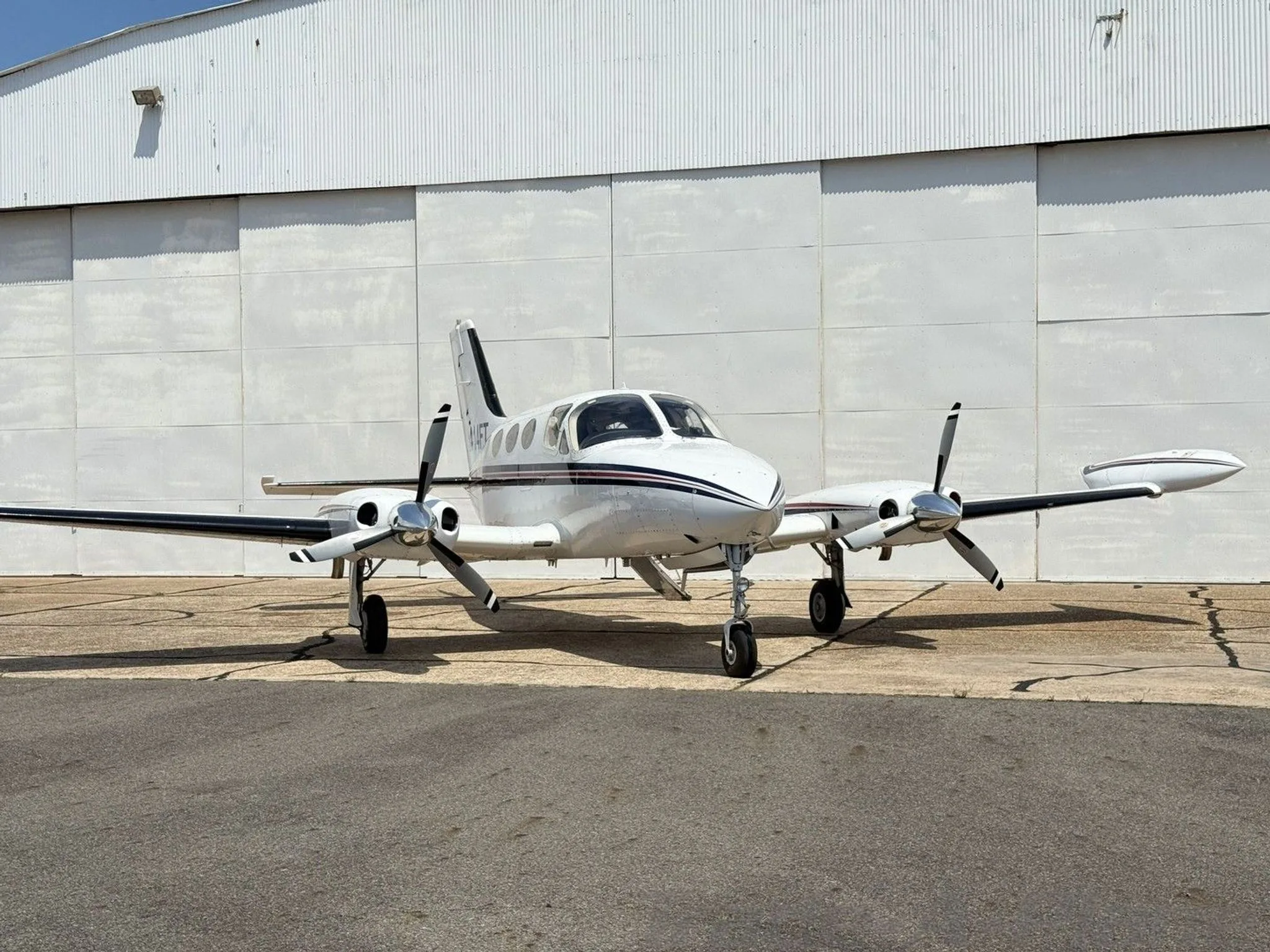
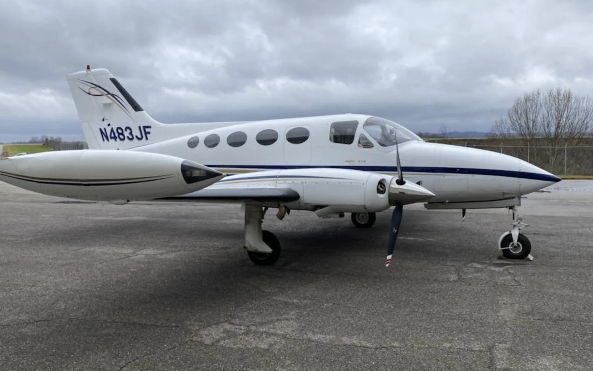

Free — save the 414 to your watchlist and track it in one place.
More CESSNA 414manuals & documents
See all 33 →- C-414 Initial/Transition Ground Training Student Guide - Tom GorskiSystems Description
- C-414A Transition Flight Training Student GuideV Speeds Reference
- C-414 Initial/Transition Flight Training Student Guide - Tom GorskiNormal Procedures
- NAVIGATION - STALL WARNING HORN REPLACEMENTService Bulletins
- SERVICE BULLETIN No. 058 Rev. A Turbocharger - Back Plate Assembly Replacement at OverhaulMaintenance Manual
- Aviation Accident Factual ReportOther Documents
- RAM Performance - Cessna 414 Series VIIPilot's Operating Handbook
- AAIB Bulletin: 4/2019 N414FZ EW/G2018/06/33Other Documents
- Type Acceptance Report TAR 6/21B/14 – Cessna 400 SeriesOther Documents
- Aviation Accident Final ReportOther Documents
- C-414 NORMAL CHECKLISTPilot's Operating Handbook
- Airworthiness Directive Schedule Aeroplanes Cessna 414 SeriesService Bulletins
If you fly the CESSNA 414, you may also be researching these.



In this document
Purpose
The purpose of this advisory circular is to provide a specification that airports can use when procuring Aircraft Rescue and Fire Fighting (ARFF) vehicles. It aims to standardize the vehicle selection process and ensure compliance with federal regulations.
Scope
The AC covers the procurement process for ARFF vehicles, including the selection of vehicle requirements and the production of formal specifications. It is based on the minimum requirements established by Title 14 CFR Part 139 and relevant NFPA standards.
ARFF Vehicle Requirements
The requirements for ARFF vehicles are established by Title 14 CFR Part 139.317, which outlines the necessary firefighting agents and vehicle capabilities based on the airport's ARFF index. The document provides decision logic diagrams to assist in determining the appropriate vehicle and agent requirements.
Interactive Procurement Specification
The document includes interactive worksheets that allow users to select the appropriate features for ARFF vehicles. These selections will populate the corresponding procurement specifications, ensuring that the vehicles meet the necessary performance requirements.
Principal Changes
The AC incorporates several principal changes from previous versions, including updates to the NFPA standards referenced, the addition of a checklist for delivery packages, and changes in terminology to align with current guidelines.
Safety notes
- Ensure all ARFF vehicles comply with federal safety standards and guidelines.
- Regular maintenance and inspection of ARFF vehicles are crucial for operational readiness.
Full document text
U.S. Department of Transportation Federal Aviation Administration Advisory Circular Subject: Guide Specification for Aircraft Rescue and Fire Fighting (ARFF) Vehicles Date: Draft Initiated By: AAS-300 AC No: 150/5220-10F Change: 1 Purpose. 1 This advisory circular (AC) provides an interactive specification that airports can use in 2 procuring Aircraft Rescue and Fire Fighting (ARFF) vehicles. 3 2 Cancellation. 4 AC 150/5220-10E, Guide Specification for Aircraft Rescue and Fire Fighting (ARFF) 5 Vehicles, dated June 1, 2011, is cancelled. 6 3 Scope. 7 The three main phases of the ARFF vehicle procurement process are presented in this 8 AC, including the: 9 1. Description of the vehicle selection process, 10 2. Selection of vehicle requirements, and 11 3. Production of a formal specification. 12 This AC contains information based on the minimum ARFF vehicle requirements 13 established by Title 14 of the Code of Federal Regulations (CFR) Part 139, Certification 14 of Airports. The AC is also based on the Federal Aviation Administration (FAA) 15 additions, exemptions, or amendments made to National Fire Protection Association 16 (NFPA) 414, Standard for Aircraft Rescue and Fire-Fighting Vehicles (2020 Edition), 17 and NFPA 1901, Standard for Automotive Fire Apparatus (2016 Edition). Only ARFF 18 vehicles and associated vehicle training equipment are discussed in this AC. Other 19 related items, such as the communications equipment, tools, and clothing used in fire 20 fighting, are not covered. However, that information can be found in other guidance 21 material, such as AC 150/5210-14, Aircraft Rescue and Fire Fighting Equipment, 22 Tools, and Clothing. 23 4 Application. 24 The FAA recommends the guidance and specifications in this AC for procuring ARFF 25 vehicles. In general, use of this AC is not mandatory. However, use of this AC is 26 4/6/2022 D R A F T AC 150/5220-10F ii mandatory for the acquisition of ARFF vehicles through the Airport Improvement 27 Program (AIP) or Passenger Facility Charge (PFC) Program. See Grant Assurance No. 28 34, Policies, Standards, and Specifications, and PFC Assurance No. 9, Standards and 29 Specifications. For certificated airports, in the event of a conflict, Part 139 takes 30 precedence over all other documents identified in the AC. For any allowable options 31 requested by the user that require justification, the appropriate text will be entered in the 32 space provided for FAA Airport District Office (ADO) or Regional staff review and 33 approval. Additions, exceptions, amendments and options are noted, referencing 34 applicable NFPA 414 paragraphs. Features or design details not listed as required or 35 optional in this document are generally considered not necessary. However, special 36 circumstances or conditions may be addressed through the FAA’s Modification to 37 Standards procedures (see FAA Order 5300.1, Modifications to Agency Airport Design, 38 Construction, and Equipment Standards). 39 5 Principal Changes. 40 The AC incorporates the following principal changes: 41 1. Reformatted to reflect features required and allowable when vehicles are acquired 42 using federal financial assistance. 43 2. Deleted Classes 2 and 3. 44 3. Deleted former Appendix A, Previous FAA Additions, Exemptions, or Amendments 45 to NFPA 414. 46 4. Added Appendix B, “Checklist for Delivery Package.” 47 5. Updated reference material to NFPA 414, 2020 edition. 48 6. Changed terminology “high reach extendable turret” to “boom-mounted turret” per 49 NFPA 414 guidelines. 50 7. Halogenated agent is now referred to as clean agent. 51 8. 500 pounds of potassium-based dry chemical is an allowable substitution. 52 9. Updated the format and made editorial changes throughout. 53 6 Using this Document. 54 The intent of the interactivity provided in this AC is to allow its user to select the 55 appropriate features needed to populate the associated procurement specification with 56 the FAA-approved wording. We recommend downloading the AC to your computer so 57 you may save your work as needed. When complete, the associated procurement 58 specification may be printed, signed, and submitted in hardcopy form. 59 Hyperlinks (allowing the reader to access documents located on the internet and to 60 maneuver within this document) are provided throughout this document and are 61 identified with underlined text. When navigating within this document, return to the 62 previously viewed page by pressing the “ALT” and “ ←” keys simultaneously. 63 4/6/2022 D R A F T AC 150/5220-10F iii 7 Related Documents. 64 ACs and Orders referenced in the text of this AC do not include a revision letter, as they 65 refer to the latest version. 66 1. FAA AIP Handbook 67 2. AC 150/5210-5, Painting, Marking, and Lighting of Vehicles Used on an Airport 68 3. AC 150/5210-14, Aircraft Rescue and Fire Fighting Equipment, Tools, and 69 Clothing 70 4. AC 150/5210-19, Driver’s Enhanced Vision System (DEVS) 71 5. AC 150/5210-25, Performance Specification for Airport Vehicle Runway Incursion 72 Warning Systems (RIWS) 73 6. FAA Order 5300.1, Modifications to Agency Airport Design, Construction, and 74 Equipment Standards 75 7. Part 139, Certification of Airports 76 8. NFPA 414, Standard for Aircraft Rescue and Fire-Fighting Vehicles (2020 Edition), 77 https://www.nfpa.org/ 78 9. NFPA 1901, Standard for Automotive Fire Apparatus (2016 Edition), 79 https://www.nfpa.org/ 80 8 Where to Find this AC. 81 You can view a list of all ACs at 82 https://www.faa.gov/regulations_policies/advisory_circulars/. You can view the Federal 83 Aviation Regulations at https://www.faa.gov/regulations_policies/faa_regulations/. 84 9 Feedback on this AC. 85 If you have suggestions for improving this AC, you may use the Advisory Circular 86 Feedback form at the end of this AC. 87 John R. Dermody Director of Airport Safety and Standards 4/6/2022 D R A F T AC 150/5220-10F iv Page Intentionally Blank
Show full textShow less
4/6/2022 D R A F T AC 150/5220-10F CONTENTS Paragraph Page v Chapter 1. The Vehicle Selection Process ................................................................................ 1-1 88 1.1 General. ......................................................................................................................... 1-1 89 1.2 Background. .................................................................................................................. 1-1 90 1.3 ARFF Vehicle Requirements. ....................................................................................... 1-1 91 1.4 Step 1 – Determining Replacement Need. .................................................................... 1-5 92 1.5 Step 2 – Determining the Airport’s ARFF Index.......................................................... 1-6 93 1.6 Step 3 – Determining Agent Requirements. ................................................................. 1-7 94 1.7 Step 4 – Determining Vehicle Requirements................................................................ 1-9 95 Chapter 2. Interactive Procurement Specification - Input .................................................... 2-1 96 2.1 General. ......................................................................................................................... 2-1 97 2.2 Airport Requirements Worksheet: Class 1 ................................................................... 2-3 98 2.3 Airport Requirements Worksheet: Class 4 ................................................................. 2-11 99 2.4 Airport Requirements Worksheet: Class 5 ................................................................. 2-20 100 Chapter 3. Interactive Procurement Specification – Output ................................................. 3-1 101 3.1 Vehicle Procurement Specification, Class 1 ................................................................. 3-1 102 3.2 Vehicle Procurement Specification, Class 4 ............................................................... 3-35 103 3.3 Vehicle Procurement Specification, Class 5 ............................................................... 3-71 104 Appendix A. ARFF Vehicle Training Equipment................................................................ A-1 105 A.1 Aircraft Skin Penetration Training Device .................................................................. A-1 106 A.2 Computer Training System .......................................................................................... A-1 107 Appendix B. Checklist for Delivery Package ........................................................................B-1 108 FIGURES 109 Figure 1-1. Advisory Circular (AC) Flowchart .......................................................................... 1-1 110 Figure 1-2. Decision Logic Diagram Summary for Index A or B Airports ................................ 1-2 111 Figure 1-3. Decision Logic Diagram Summary for Index C Airports ........................................ 1-3 112 Figure 1-4. Decision Logic Diagram Summary for Index D or E Airports ................................ 1-4 113 4/6/2022 D R A F T AC 150/5220-10F CONTENTS Paragraph Page vi Figure 2-1. Specification Completion Process............................................................................ 2-1 114 TABLES 115 Table 1-1. Sample Aircraft Types by Airport Index ................................................................... 1-7 116 Table 1-2. Fire Fighting Extinguishing Agent Minimum Capacities ......................................... 1-8 117 Table 1-3. Airport Index and Vehicle Class Requirements ........................................................ 1-9 118 Table 1-4. Usable Capacities .................................................................................................... 1-11 119 4/6/2022 D R A F T AC 150/5220-10F 1-1 Chapter 1. THE VEHICLE SELECTION PROCESS 120 1.1 General. 121 This chapter provides an overview of the ARFF vehicle selection process. As shown in 122 Figure 1-1, the considerations and requirements outlined in this chapter will be used to 123 enter the appropriate information in Chapter 2 (vehicle procurement worksheets) which 124 provides the corresponding output in Chapter 3 (vehicle procurement specifications). 125 Figure 1-1. Advisory Circular (AC) Flowchart 126 127 1.2 Background. 128 ARFF vehicles are designed to provide an invaluable service to (a) the commercial and 129 private aviation industry, (b) safety of the passengers, and (c) the cargo they transport. 130 The aviation industry is reliant on prompt and effective fire and rescue services during 131 aircraft emergencies. These services include fire containment and suppression, 132 passenger and crew rescue, airframe and cargo preservation, and maintenance of the site 133 to aid in after-incident investigations. The vehicles that airport fire departments employ 134 serve as the medium to deliver fire fighters, specialized tools and equipment, and fire 135 fighting agents to the scene of an aircraft incident. ARFF vehicles are designed to 136 perform specific functions, constructed for longevity and ease of maintenance. 137 1.3 ARFF Vehicle Requirements. 138 The requirements for ARFF vehicles to transport specific quantities and types of fire 139 fighting agents are established by Title 14 CFR Part 139.317, Aircraft Rescue and 140 Firefighting: Equipment and Agents. Decision logic diagrams (Figure 1-211 , Figure 1-3, 141 and Figure 1-4) identify an airport index and the decision process concerning what 142 vehicles and agents an airport must have as a minimum based on that index. However, 143 there are options in Part 139.317 that allow flexibility in the configuration of fire 144 fighting vehicle agent delivery systems. These options include a selection of the type of 145 dry chemical agent (sodium versus potassium based), quantity by type of dry chemical 146 agent, use of an approved clean agent in lieu of dry chemical, and a minimum of 100 147 gallons water/foam. 148 Selection Process Overview Vehicle Procurement Worksheets (input) Vehicle Procurement Specifications (output) Chapter 1 Chapter 2 Chapter 3 Selection Process Overview Vehicle Procurement Worksheets (input) Vehicle Procurement Specifications (output) Chapter 1 Chapter 2 Chapter 3 4/6/2022 D R A F T AC 150/5220-10F 1-2 Figure 1-2. Decision Logic Diagram Summary for Index A or B Airports 149 150 Index A Index B 1,500 gal Water & foam 2 Vehicles Vehicle 2 1,500 gal Water & foam (Class 4) Vehicle 1 (Class 1) Sodium dry chemical 500 lbs Approved clean agent 500 lbs Potassium 500 lbs & 100 gal water & foam Sodium dry chemical 500 lbs Approved clean agent 500 lbs Potassium 500 lbs & 100 gal water & foam Aircraft P 90 ft and < 126 ft Aircraft < 90 ft or Select Airport Index A or B Select number of ARFF vehicles Select one agent Select one more agent Sodium dry chemical 500 lbs Approved clean agent 500 lbs 1 Vehicle (Class 4) 1 Vehicle (Class 1) Select one agent or or or or or or and or 4/6/2022 D R A F T AC 150/5220-10F 1-3 Figure 1-3. Decision Logic Diagram Summary for Index C Airports 151 152 Index C Vehicle 2 3,000 gal Water & foam (Class 5) Vehicle 1 1,500 gal Water & foam (Class 4) Sodium dry chemical 500 lbs Vehicle 1 (Class 1) Potassium 500 lbs & 100 gal water & foam Vehicle 2 1,500 gal Water & foam (Class 4) Vehicle 3 3,000 gal Water & foam (Class 5) Aircraft P 126 ft and < 159 ft Select Airport Index C Select number of ARFF vehicles 2 Vehicle combination 3 Vehicles Totaling at least 3,000 gallon capacity Select one more agent Select one agent Approved clean agent 500 lbs Approved clean agent 500 lbs Sodium dry chemical 500 lbs or or or or or and Sodium dry chemical 500 lbs Approved clean agent 500 lbs Potassium 500 lbs & 100 gal water & foam Select one agent Vehicle 1 (Class 1) or or or 2 Vehicles 2 Vehicle combination Vehicle 2 3,000 gal Water & foam (Class 5) 2 Vehicle combination Vehicle 1 1,500 gal Water & foam (Class 4) Vehicle 2 1,500 gal Water & foam (Class 4) Sodium dry chemical 500 lbs Select one more agent Approved clean agent 500 lbs or or and Sodium dry chemical 500 lbs Select one more agent Approved clean agent 500 lbs or or and or or 4/6/2022 D R A F T AC 150/5220-10F 1-4 Figure 1-4. Decision Logic Diagram Summary for Index D or E Airports 153 154 Index E Index D 3 Vehicles, totaling at least 4,000 gallon capacity Vehicle 1 (Class 1) Sodium dry chemical 500 lbs Approved clean agent 500 lbs Potassium 500 lbs & 100 gal water & foam Vehicle 3 water & foam Vehicle 2 water & foam 3 Vehicles, totaling at least 6,000 gallon capacity Vehicle 1 (Class 1) Sodium dry chemical 500 lbs Approved clean agent 500 lbs Potassium 500 lbs & 100 gal water & foam Vehicle 3 water & foam Vehicle 2 water & foam Aircraft > 200 ft Select Airport Index D or E Aircraft P 159 ft and < 200 ft Select one agent Select one agent or or or or or or 4/6/2022 D R A F T AC 150/5220-10F 1-5 There are four (4) basic steps to establish and validate requirements for an ARFF 155 vehicle. 156 1. Step 1. Determine the need to replace an existing vehicle or procure a new vehicle. 157 Refer to paragraph 1.4. 158 2. Step 2. Determine the airport’s ARFF index. Consult paragraph 1.5 of this AC and 159 Part 139.315, Aircraft Rescue and Firefighting: Index Determination. 160 3. Step 3. Determine the fire fighting vehicle agent requirements. Consult paragraph 161 1.6 of this AC and Part 139.317. 162 4. Step 4. Determine the ARFF vehicle requirements based on Steps (1), (2), and (3) 163 above by consulting paragraph 1.7 and Chapter 2 of this AC which are based on 164 NFPA 414. 165 1.4 Step 1 – Determining Replacement Need. 166 Fire departments and manufacturers of fire fighting apparatus do not have hard and fast 167 rules as to when a vehicle is recommended for replacement. However, the fire 168 equipment manufacturing industry does develop, as part of their customer service focus, 169 forecast models based on life expectancy and life cycle operating and maintenance 170 costs. These models predict hours of operation, mileage, material wear and longevity, 171 and operating costs. On average, an ARFF vehicle has a 15-year service life cycle or as 172 maintenance dictates as identified by the FAA Airport Certification Safety Inspector 173 (ACSI) and, in many cases, even longer based on an airport’s level of activity. 174 Consider the following items as relevant factors when determining fire fighting vehicle 175 replacement (Note: See AIP Handbook to determine AIP Eligibility): 176 1. Reliability and serviceability are questionable. 177 2. Parts for repair (including after-market) are no longer available. 178 3. Annual operating cost becomes excessive. 179 4. Service life has been extended beyond the vehicle’s normal field service life. 180 5. Repair cost exceeds 75% of the current estimated value of a new apparatus. All 181 remanufactured ARFF vehicles must meet the standards of this AC. 182 Remanufactured ARFF vehicles must not exceed 75% of the cost of new 183 manufactured vehicles of the same class with comparable options. 184 Remanufacturing costs that exceed 75% of a new vehicle are not considered best 185 value engineering for federal funding. 186 6. Introduction of different design aircraft to the airport that changes the airport’s 187 ARFF index. 188 7. Relative overall age of the airport fire fighting vehicle fleet, to allow for 189 programmed replacement over a span of years. 190 8. Vehicle model design changes that offer a significant increase in safety to the 191 occupants of the vehicle during response. 192 4/6/2022 D R A F T AC 150/5220-10F 1-6 1.5 Step 2 – Determining the Airport’s ARFF Index. 193 An airport’s ARFF index is determined by the requirements of Part 139.315. See Part 194 139.5 for definitions of air carrier aircraft, air carrier operations, and average daily 195 departures. 196 1. An airport’s ARFF index is determined by a combination of two factors. These 197 include: 198 a. The length of air carrier aircraft. 199 b. The average daily departures of air carrier aircraft. 200 i. If there are five or more average daily departures of air carrier aircraft in a 201 single Index group serving that airport, the longest Index group with an 202 average of five or more daily departures is the Index required for the 203 airport. 204 ii. If there are fewer than five average daily departures of air carrier aircraft 205 in a single Index group serving that airport, the next lower Index from the 206 longest Index group with air carrier aircraft in it is the Index required for 207 the airport. The minimum designated index is Index A. 208 2. Air carrier aircraft are grouped by length to determine an airport’s index as 209 described below: 210 a. Index A includes aircraft less than 90 feet in length. 211 b. Index B includes aircraft at least 90 feet but less than 126 feet in length. 212 c. Index C includes aircraft at least 126 feet but less than 159 feet in length. 213 d. Index D includes aircraft at least 159 feet but less than 200 feet in length. 214 e. Index E includes aircraft at least 200 feet in length. 215 3. See Table 1-1 for a general sampling of various aircraft and the indices they are 216 assigned based on their respective lengths. The list is not all inclusive and is 217 provided to serve as an example only. To ensure accuracy, consult with airlines 218 and/or aircraft manufacturers to obtain aircraft lengths. 219 4/6/2022 D R A F T AC 150/5220-10F 1-7 Table 1-1. Sample Aircraft Types by Airport Index 220 Type Aircraft* Index A Index B Index C Index D Index E ATR 72 X Beech Kingaire 200 X Bombardier CRJ100/200 X Cessna 414 X DeHavilland Dash 8 X Gulfstream 3 X Lear 55 X Piper Cheyenne 2 X Airbus A320 300 X BAE 146-200 X Boeing 737-300 X Bombardier CRJ700/900 X Embraer 170/175 X Embraer 190 X Boeing 757 X Boeing 737-800 X Bombardier CRJ1000 X Embraer 195 X MD-88 X Airbus A300 X Airbus A330-200 X Airbus A350-800 X Boeing 767-300 X Boeing 787-8 X Airbus A330-300 X Airbus A340 300 X Airbus A350-900 X Airbus A380 X Antonov AN-225 X Boeing 747-200 X Boeing 747-8 X Boeing 787-9 X * Sources: Data has been extracted from NFPA, International Civil Aviation Organization (ICAO), FAA, 221 and aircraft manufacturer documents to validate the aircraft placement into a specific index. 222 1.6 Step 3 – Determining Agent Requirements. 223 The minimum levels of fire fighting agents by type and quantity within a vehicle system 224 to support a specific airport index are addressed in Part 139.317. The FAA’s 225 standardized ARFF vehicle classifications are Classes 1, 4, and 5. These classifications 226 segregate vehicles by the type of fire fighting agent employed on the vehicle and the 227 vehicle’s agent carrying capacity. 228 4/6/2022 D R A F T AC 150/5220-10F 1-8 1.6.1 Types of Fire Fighting Agents. 229 There are four types of fire fighting agents (either as a single agent or in combination 230 with another agent) that are carried on ARFF vehicles. These agents can include: 231 1. Sodium-based dry chemical. 232 2. Potassium-based dry chemical. 233 3. Approved clean agents. 234 4. Water/foam. 235 Each ARFF vehicle is designed to be capable of carrying and delivering the specific 236 types of fire fighting agents cited above either as a standalone system or complementary 237 to one another. The types of agents are based on their respective extinguishing 238 effectiveness and compatibility to complement each other, hence the term 239 “complementary agent.” NFPA refers to an “auxiliary agent.” This term has the same 240 meaning as “complementary agent” used herein. 241 Table 1-2. Fire Fighting Extinguishing Agent Minimum Capacities 242 Airport Index Vehicle Class Minimum Rated Capacities Options Primary Agent Complementary Agent A, B, C, D, E 1 500 lbs sodium-based dry chemical only None A, B, C, D, E 1 100 gallons of water/foam 500 lbs potassium-based dry chemical A, B, C, D, E 1 100 gallons of water/foam 500 lbs approved clean agent A, B, C, D, E 1 100 gallons of water/foam with supplemental Compressed Air Foam System (CAFS) 500 lbs sodium-based dry chemical A, B, C, D, E 1 100 gallons of water/foam with supplemental CAFS 500 lbs potassium-based dry chemical A, B, C, D, E 1 100 gallons of water/foam with supplemental CAFS 500 lbs approved clean agent B 4 1500 gallons water/foam 500 lbs sodium-based dry chemical B 4 1500 gallons water/foam 500 lbs approved clean agent B, C, D, E 4 1500 gallons water/foam 500 lbs potassium-based dry chemical C, D, E 5 3000 gallons water/foam 500 lbs sodium-based dry chemical C, D, E 5 3000 gallons water/foam 500 lbs potassium-based dry chemical C, D, E 5 3000 gallons water/foam 500 lbs approved clean agent D, E 5 4500 gallons water/foam 500 lbs sodium-based dry chemical D, E 5 4500 gallons water/foam 500 lbs potassium-based dry chemical D, E 5 4500 gallons water/foam 500 lbs approved clean agent 1.6.2 Vehicle Agent Carrying Capacity. 243 The agent carrying and delivery capability of an ARFF vehicle is limited by several 244 factors. These include chassis design, engine and drive train, axle capacity, fire fighting 245 4/6/2022 D R A F T AC 150/5220-10F 1-9 systems, and the manufacturer’s capability to provide either a commercial or custom 246 produced ARFF vehicle. Refer to 1 Table 1-31 for summaries of the three classes of ARFF 247 vehicles and the fire fighting agent requirements for each class of vehicle. 248 Table 1-3. Airport Index and Vehicle Class Requirements 249 Class 1 Class 4 Class 5 100 Gallon Water/Foam 1500 Gallon Water/Foam 3000-4500 Gallon Water/Foam and Dry Chemical (500 lbs sodium- or 500 lbs potassium-based), or Approved Clean Agent (500 lbs) Airport Index (Note 1) (Note 1) A 1 N/A N/A B 1 1 (Note 2) N/A C 1 2 N/A 1 1 1 (3,000 Gallon) D 1 1 1 E 1 N/A 2 1 1 1 Note 1: For Index A-E, a Class 1 vehicle is required (see Note 2 for exception). 250 Note 2: If the Class 4 vehicle has Dry Chemical/Approved Clean Agent, a Class 1 vehicle is not required 251 for an Index B Airport. If the Class 4/5 vehicle does not have Dry Chemical/Approved Clean 252 Agent, a Class 1 vehicle is required. 253 1.7 Step 4 – Determining Vehicle Requirements. 254 These specifications incorporate NFPA 414, with additions, exceptions, and 255 amendments cross referenced to the paragraph numbers in NFPA 414, Chapter 4, ARFF 256 Vehicles and Chapter 6, Acceptance Criteria. Incorporated by reference are 257 requirements of NFPA 1901 where applicable. Optional equipment cited in Annex A of 258 NFPA 414 is not covered by these specifications except where noted. For ancillary 259 equipment, see AC 150/5210-14, Aircraft Rescue Fire Fighting Equipment, Tools and 260 Clothing. The three specifications aligned to the three vehicle classifications are 261 generic in nature, describe vehicles’ performance requirements and are not name brand 262 product specific. Each contains a series of interactive worksheets, developed to be used 263 on ©Microsoft Windows operating systems, that allows the user to select requirements 264 4/6/2022 D R A F T AC 150/5220-10F 1-10 that populate the procurement specifications based on those choices. The three 265 specifications are as follows: 266 1.7.1 Class 1 ARFF Vehicle. 267 This Procurement Specification covers a commercially produced 4-wheel drive, diesel 268 engine driven ARFF vehicle for an Index A through E airport. It includes the choice of 269 a vehicle with a minimum 500 pounds (lbs) sodium based dry chemical system, or a 500 270 lb approved clean agent system, or a 500 lbs potassium-based dry chemical system with 271 100 gallons (gal) of water/foam. The water/foam may be pre-mixed and contained in 272 one pressurized tank or supplemented with a CAFS. 273 1.7.2 Class 4 ARFF Vehicle. 274 This Procurement Specification covers a commercially produced diesel engine driven 275 ARFF vehicle for an Index B, C, or D airport. It includes a 1500-gallon water/foam fire 276 suppression system: 277 1. with a complementary 500 potassium-based or 500 lb sodium-based Dry Chemical 278 system only, 279 2. with a complementary 500 lb Approved Clean Agent system only, 280 1.7.3 Class 5 ARFF Vehicle. 281 This Procurement Specification covers a commercially produced diesel engine driven 282 ARFF vehicle for an Index D or E airport. It includes a 3000 or 4500-gallon 283 water/foam fire suppression system: 284 1. with a complementary 500 lb Dry Chemical system only, 285 2. with a complementary 500 lb Approved Clean Agent system only. 286 1.7.4 Relation to NFPA Usable Capacities. 287 • Performance requirements for Class 1 vehicles follow the NFPA 414 performance 288 requirements for ≥120 and ≤528 gallons. 289 • Performance requirements for Class 4 vehicles follow the NFPA 414 performance 290 requirements for >528 and ≤1585 gallons. 291 • Performance requirements for Class 5 vehicles follow the NFPA 414 performance 292 requirements for >1585 gallons. 293 4/6/2022 D R A F T AC 150/5220-10F 1-11 Table 1-4. Usable Capacities 294 Water or Water/Foam Solution Dry Chemical or Clean Agent Class of Vehicle Gallons (U.S.) Pounds 1 100 500 (Sodium Based) 500 (Potassium Based) 500 (Clean Agent) 4 1,500 See Part 139.317 5 3,000 to 4,500 in 500-gallon increments See Part 139.317 4/6/2022 D R A F T AC 150/5220-10F 1-12 Page Intentionally Blank 4/6/2022 D R A F T AC 150/5220-10F 2-1 Chapter 2. INTERACTIVE PROCUREMENT SPECIFICATION - INPUT 295 2.1 General. 296 Interactive worksheets in this chapter are designed to allow the users to select options 297 and provide inputs to procurement specifications based on their requirements. 298 Chapter 3 contains specifications for Class 1, 4, and 5 ARFF vehicles. The 299 corresponding specification will be populated automatically based on the worksheet 300 item selections and inputs. For example, the worksheets in paragraph 2.2 populate the 301 Class 1 specification. The document has been aligned to the performance requirements 302 of NFPA 414 and incorporates amended criteria. Specifically, all the options that are 303 allowed by the FAA are included. The numbering system listed in this section directly 304 corresponds to Chapter 4 in the NFPA 414 2020 edition. To properly use this 305 document, first refer to NFPA 414 for the base requirements, then refer to this advisory 306 circular for any additions, exceptions, amendments or selections. When an option 307 requires justification for funding under federal financial assistance programs, rationale 308 must be provided by the user for the FAA Airports Regional or District Office review 309 and approval. This document will serve as the baseline for submission of specifications 310 for AIP and PFC funded vehicles – thus it is a specification for a commercially 311 available vehicle without extraneous items that an airport may fund on its own. 312 Extraneous items requested by an airport cannot be used in determining the low 313 responsive bidder when AIP or PFC funding is used. Follow the process in Figure 2-1 314 to produce the required specifications. FAA submittal pages follow each specification. 315 Note: Commercially manufactured chassis used to manufacture Class 1 vehicles must 316 comply with Federal Motor Vehicle Safety Standards (FMVSS). If the AC and FMVSS 317 differ, the more demanding applies. 318 Figure 2-1. Specification Completion Process 319 Class 1 → 1 Worksheets → Review 1 Class 1 Specification1 Print Class 1 Specification Class 4 → 1 Worksheets → Review 1 Class 4 Specification1 Print Class 4 Specification Class 5 → 1 Worksheets → Review 1 Class 5 Specification1 Print Class 5 Specification No printing at this time For more information on the development and use of the equipment, agents, and 320 technologies discussed in the following pages, visit the 1 FAA Airport Technology 321 Research and Development Branch Home Page1 , where detailed technical reports (i.e. 322 Technical Notes) can be found in the 1 Aircraft Rescue and Fire Fighting Technology1 323 section. 324 4/6/2022 D R A F T AC 150/5220-10F 2-2 Page Intentionally Blank 4/6/2022 D R A F T AC 150/5220-10F Class 1 Worksheets 2-3 2.2 Airport Requirements Worksheet: Class 1 325 Select one in each category and enter requested information Airport name: Airport POC: Airport Code Identifier: Airport address: Phone number: Grant number: ________________________________________ ________________________________________ ________________ ________________________________________ ________________________________________ ________________________________________ Airport index A B C D E Primary extinguishing agent 500 lb sodium-based dry chemical 500 lb potassium-based dry chemical 500 lb approved clean agent water/foam (100 gal) Complementary extinguishing agent system 500 lb sodium-based dry chemical 500 lb potassium-based dry chemical 500 lb approved clean agent none Primary extinguishing agent discharge location bumper turret roof turret hose reel bumper turret and hose reel Complementary extinguishing agent discharge location bumper turret hose reel bumper turret and hose reel roof turret and hose reel none Water/foam discharge system pressurized pre-mix pressurized pre-mix plus supplemental CAFS none If foam is provided, specify percent concentrate 3% 6% 4/6/2022 D R A F T AC 150/5220-10F Class 1 Worksheets 2-4 Select one in each category and enter requested information Primary Turret Nozzle a water/foam discharge a complementary agent discharge mounted parallel to the water/foam discharge a complementary agent discharge of the entrainment type an approved clean agent Hose Reel Nozzle a water/foam discharge a complementary agent discharge mounted parallel to the water/foam discharge a complementary agent discharge of the entrainment type an approved clean agent none Cab doors 2 doors 4 doors Cab doors lockable yes no Compartment doors lockable yes no Turret power manual power assisted with manual override power assisted with secondary parallel controls powered by an alternative source power assisted without secondary control 4/6/2022 D R A F T AC 150/5220-10F Class 1 Worksheets 2-5 Standard/Specialized Equipment Requirements Worksheet 326 Standard Requirements Specialized Requirements Selection Justification Elevation less than 2,000 feet Is elevation 2,000 feet or more? Yes No Enter actual elevation if over 2,000 feet: __________ feet Equipment capable of operating at -40° to 110°F Is standard temperature range equipment adequate? Yes over 110°F Tire size Large tires Yes No Radiator shutters Are radiator shutters required? Yes No 4/6/2022 D R A F T AC 150/5220-10F Class 1 Worksheets 2-6 Select one: Runway Incursion Warning Systems (RIWS) Yes No See AC 150/5210-25 for guidance on RIWS options. If RIWS is required, provide the following information: Power source Select all that apply: direct hardwire power connection 12V quick plug-in battery battery backup System type preconfigured system custom system If a custom RIWS system is required, provide the following information: Check all options that apply custom areas additional/custom audible signals additional/custom visual signals Additional features requiring justification. Check all that apply. historical tracking and vehicle trails zone creation network capability multiple-vehicle tracking document display system integration with: FOD detection equipment ADS-B ASDE-X DEVS multilateration and Airport Surface Surveillance Capability (ASSC) airfield maintenance and inspection programs Justification for additional RIWS features 4/6/2022 D R A F T AC 150/5220-10F Class 1 Worksheets 2-7 Select applicable subsystem(s) Select applicable related features Low-Visibility Enhanced Vision subsystem Driver’s Enhanced Vision System (DEVS) base system DEVS Options Add navigation subsystem If navigation subsystem is chosen, check all that apply: integrated airport grid map incident location routing navigation support staging areas/scenario planning drawing tools user defined zones, routes, and areas CAD layers vehicle radio frequency (RF) data link Add tracking subsystem If tracking subsystem is chosen, select message exchange time: Enter value ________ seconds Vehicle Space Requirements Worksheet 327 Minimum requirements Facility dimensions sufficient for fully loaded vehicle with turrets bedded? For insufficient dimensions, enter minimum requirement: Length 360 inches Yes No __________ inches Width, including mirrors 100 inches Yes No __________ inches Height 120 inches Yes No __________ inches Standard requirements Specialized requirements Selection / Details Seat Type/ Self- Contained Breathing Apparatus (SCBA) Driver Standard (hard/fixed back) Turret Standard (hard/fixed back) SCBA #3 Standard (hard/fixed back) SCBA N/A #4 Standard (hard/fixed back) 4/6/2022 D R A F T AC 150/5220-10F Class 1 Worksheets 2-8 Standard requirements Specialized requirements Selection / Details SCBA N/A Self-Contained Breathing Apparatus (SCBA) mounting type Enter SCBA equipment manufacturer name and model number: ______________________ 2216 psi 4500 psi 30-minute bottles 60-minute bottles Mirrors Electrically heated heads Yes No Towing Device Type Pintle Hook Ball Mount Emergency warning lights Lighting type (LED) rotating beacon strobe MADAS Monitoring and Data Acquisition System (MADAS) capability Yes No Windows Control system electric manual Floodlights Style to include adjustment knuckle fixed telescoping Spot, flood, and scene lights Lighting type halogen LED HID Additional wiring (power, control, antenna) Any that would require partial dismantling of vehicle components (e.g., cab headliner) if added after delivery. Specify antennas, wire types and location of antennas and wire terminations. Lubrication system Continuous duty cycle for suspension parts and other mechanical equipment joints. Yes No 4/6/2022 D R A F T AC 150/5220-10F Class 1 Worksheets 2-9 Provisions for storing/mounting the following equipment [quantity]: Only the storing/mounting will be provided by the vehicle manufacturer, not the equipment. When specifying provisions for storing/mounting, be mindful of the total space available; not all items will fit on one truck. 36” axe, pick head, fiberglass handle [1] Halligan bar – 36” [1] axe, flat head, fiberglass handle – 36” with mounting bracket [1] 36” crowbar [1] cutter, cable [1]: 24” 36” hacksaw, 12” [1] hammer, 1¼ lb (maul) [1] hammer, 16 oz, non-sparking [1] hammer, sledge, 8 lb with fiberglass handle [1] knife, rescue [1] V-blade (harness cutting tool) [2] pliers, side cutting, 7” [1] adjustable wrench, 8” [1] locking pliers, 10” [1] plug, fuel line [6] 6 screw drivers [1 set] shears, sheet metal [1] tool bag to carry all hand tools (cutter through shears, above) [1] blanket, fire resistant with storage pouch [1] wheel chocks – one set with mounting brackets [1] ladder, ≤ 24 ft overall length with mounting brackets [1]: _______ ft extension "A-frame" rechargeable flashlights chargers to be mounted in cab wired into vehicle electrical system for charging [2] pike pole, 8 ft [2] pike pole with 4 ft “D” handle [1] rescue kit, pneumatic air hammer / chisel standard duty type, complete with spare air cylinder, carrying case and various tips [1] rescue saw with spare blades [1 per station] 14” for A, B, C airports 16” for D, E airports rope, 100 ft - 5/8” diameter [2]20B:C fire extinguishers: 1 2 30 lb Class D fire extinguisher [1] skin penetrator (piercing applicator) for water or foam application, including carry case, applicator and air cylinder (only if vehicle is not equipped with a boom-mounted turret) [1] powered firefighting hydraulic rescue tool equipped with cutter, spreader and rams [1 per station] heavy duty canvas hydrant bag [1] gate valve labeled open/closed 2½” [2] female gated reducing wye, 2½” female connection x (2) 1½” male connections [1] adjustable hydrant wrench [1] 2½” spanner wrenches w/bracket [2] 1” spanner wrenches w/ bracket [2] LDH spanner wrenches w/ mounting bracket [0] reducer, non-swivel – 2½” to 1½” [2] double female coupling – 1½” [1] double female coupling – 2½” [1] double male coupling – 1½” [1] double male coupling – 2½” [1] large diameter hose (rubber / synthetic) 25 ft [0], diameter: 4½” larger: _______ inch 50 ft rubber / synthetic hose, NST [6], diameter: 2½” 3” 1½” hand line nozzle [2] digital refractometer [1 per station] foam tank drum wrench tool [1 per station] 5 gallon pail wrench [1 per station] full spine board, 6 ft [1] 18” gasoline powered fan [1 per station] ARFF vehicle medical jump kit [1] Select none 4/6/2022 D R A F T AC 150/5220-10F Class 1 Worksheets 2-10 Provisions for storing/mounting all Personal Protection Equipment (PPE), to be part of a matching ensemble that meets current NFPA 1971 standards: Only the storing/mounting will be provided by the vehicle manufacturer, not the equipment. When specifying provisions for storing/mounting, be mindful of the total space available; not all items will fit on one truck. 1 2 3 set(s) of aluminized proximity protection suit, including coat, trousers, and gloves 1 2 3 pair(s) ARFF boots 1 2 3 complete SCBA including 30-minute bottle, face piece and PASS device 1 2 3 Nomex hood(s) 0 1 2 3 structural-style helmet(s) Any features not provided for in the standard specification will require FAA 328 approval of a Modification to Standards prior to work being done. Enter any 329 additional features desired, along with justification, on the Modification to 330 Standards page for 1 Class 11. 331 Return to Class 1 worksheet page 1 Review 1 Class 1 Specification1 Print Class 1 Specification 4/6/2022 D R A F T AC 150/5220-10F Class 4 Worksheets 2-11 2.3 Airport Requirements Worksheet: Class 4 332 Select one in each category and enter requested information Airport name: Airport POC: Airport Code Identifier: Airport address: Phone number: Grant number: ________________________________________ ________________________________________ ________________ ________________________________________ ________________________________________ ________________________________________ Airport index B C D E Primary extinguishing agent 1500 gallons water/foam Complementary extinguishing agent system 500 lb sodium-based dry chemical 500 lb potassium-based dry chemical 500 lb Approved Clean agent only complementary agent system Roof turret type Single agent turret Dual agent turret Boom-mounted turret (capable of penetrating all aircraft except the second level of an aircraft with two passenger levels) no roof turret Bumper turret type Single agent turret Dual agent turret fixed mount low volume single rate (minimum 250 GPM) bumper turret. fixed mount high volume dual rate (minimum 375/750 GPM) bumper turret. low angle high volume dual rate (minimum 375/750 GPM) bumper turret. no bumper turret. 4/6/2022 D R A F T AC 150/5220-10F Class 4 Worksheets 2-12 Select one in each category and enter requested information Structural fire fighting capability * Yes No Auxiliary generator (kilowatts) 10kW 8kW Note: * This option provides for a ‘limited’ structural fire fighting capability, in that an operator’s panel is provided 333 outside of the vehicle for the purpose of engaging and disengaging the fire pump, monitoring pressures, engine 334 RPM, flow rates, controlling water distribution, and the installation of additional suction inlets (including a priming 335 capability for drafting from a body of water or other source) and discharge outlets on the vehicle. 336 * Complementary System Options Worksheet 337 Options: Primary Turret Discharge Nozzle parallel to the foam solution discharge on the primary turret mounted on the cab roof. a combination dry chemical/ foam nozzle of the entrainment type on the primary turret mounted on the cab roof. a complementary agent discharge mounted parallel to the foam solution discharge on the primary turret mounted on the front bumper. a combination dry chemical/ foam nozzle of the entrainment type on the primary turret mounted on the front bumper. a clean agent only discharge on the primary turret mounted on the cab roof/penetrating nozzle (extendable boom only). Handline Type dry chemical - 150 feet of 1-inch dry chemical hose on a reel dual agent - 100 feet of twinned 1-inch dry chemical/ foam-water hose on a reel clean agent – 150 feet of 1-inch clean agent hose on a reel none Cab doors lockable yes no Compartment doors lockable yes no 4/6/2022 D R A F T AC 150/5220-10F Class 4 Worksheets 2-13 Standard/Specialized Equipment Requirements Worksheet 338 Standard Requirements Specialized Requirements Selection Justification Statement (limit 1000 characters) Elevation less than 2,000 feet Is elevation 2,000 feet or more? Yes No Equipment capable of operating at 40° to 110°F Is standard temperature range equipment adequate? Yes over 110°F Tires and wheels Tire bead locks Yes No Tire size Large tires Yes No Additional Seats Non-suspension type none (2 front- row seats only) 3P rdP (left side) 3rd (right side) 3P rdP and 4P thP 4/6/2022 D R A F T AC 150/5220-10F Class 4 Worksheets 2-14 Select one: Runway Incursion Warning Systems (RIWS) Yes No See AC 150/5210-25 for guidance on RIWS options. If RIWS is required, provide the following information: Power source Select all that apply: direct hardwire power connection 12V quick plug-in battery battery backup System type preconfigured system custom system If a custom RIWS system is required, provide the following information: Check all options that apply custom areas additional/custom audible signals additional/custom visual signals Additional features requiring justification. Check all that apply. historical tracking and vehicle trails zone creation network capability multiple-vehicle tracking document display system integration with: FOD detection equipment ADS-B ASDE-X DEVS multilateration and Airport Surface Surveillance Capability (ASSC) airfield maintenance and inspection programs Justification for additional RIWS features 4/6/2022 D R A F T AC 150/5220-10F Class 4 Worksheets 2-15 Select applicable subsystem(s) Select applicable related features Low-Visibility Enhanced Vision subsystem Driver’s Enhanced Vision System (DEVS) base system DEVS Options Add navigation subsystem If navigation subsystem is chosen, check all that apply: integrated airport grid map incident location routing navigation support staging areas/scenario planning drawing tools user defined zones, routes, and areas CAD layers vehicle radio frequency (RF) data link Add tracking subsystem If tracking subsystem is chosen, select message exchange time: Other (enter value) ________ seconds Vehicle Space Requirements Worksheet 339 Minimum Requirements Facility Dimensions Sufficient for fully loaded vehicle with turrets bedded? For insufficient dimensions, enter minimum requirement: Length 433 inches Yes No __________ inches Width, including mirrors 124 inches Yes No __________ inches Height 154 inches Yes No __________ inches 4/6/2022 D R A F T AC 150/5220-10F Class 4 Worksheets 2-16 Standard Requirements Specialized Requirements Selection Seat Type/ Self- Contained Breathing Apparatus (SCBA) Driver Standard (hard/fixed back) SCBA Turret Standard (hard/fixed back) SCBA #3 Standard (hard/fixed back) SCBA N/A #4 Standard (hard/fixed back) SCBA N/A Self-Contained Breathing Apparatus (SCBA) mounting type Enter SCBA equipment manufacturer name and model number: ______________________ 2216 psi 4500 psi 30-minute bottles 60-minute bottles Mirrors Electrically heated heads Yes No Back-up Camera with Monitor Yes No Emergency warning lights Lighting type (LED) rotating beacon strobe MADAS Monitoring and Data Acquisition System (MADAS) capability Yes No Electrical Cable Cord reel Yes No Air Systems Hose reel Yes No Windows Control system electric manual 4/6/2022 D R A F T AC 150/5220-10F Class 4 Worksheets 2-17 Standard Requirements Specialized Requirements Selection Floodlights Style to include adjustment knuckle Fixed Telescoping Spot, flood, and scene lights Lighting type Halogen LED HID Additional wiring (power, control, antenna) Any that would require partial dismantling of vehicle components (e.g., cab headliner) if added after delivery. Specify antennas, wire types and location of antennas and wire terminations. Lubrication system Continuous duty cycle for suspension parts and other mechanical equipment joints. Yes No 4/6/2022 D R A F T AC 150/5220-10F Class 4 Worksheets 2-18 Provisions for storing/mounting the following equipment [quantity]: Only the storing/mounting will be provided by the vehicle manufacturer, not the equipment. When specifying provisions for storing/mounting, be mindful of the total space available; not all items will fit on one truck. 36” axe, pick head, fiberglass handle [1] Halligan bar – 36” [1] axe, flat head, fiberglass handle – 36” with mounting bracket [1] 36” crowbar [1] cutter, cable [1]: 24” 36” hacksaw, 12” [1] hammer, 1¼ lb (maul) [1] hammer, 16 oz, non-sparking [1] hammer, sledge, 8 lb with fiberglass handle [1] knife, rescue [1] V-blade (harness cutting tool) [2] pliers, side cutting, 7” [1] adjustable wrench, 8” [1] locking pliers, 10” [1] plug, fuel line [6] 6 screw drivers [1 set] shears, sheet metal [1] tool bag to carry all hand tools (cutter through shears, above) [1] blanket, fire resistant with storage pouch [1] wheel chocks – one set with mounting brackets [1] ladder, ≤ 24 ft overall length with mounting brackets [1]: _______ ft extension "A-frame" rechargeable flashlights chargers to be mounted in cab wired into vehicle electrical system for charging [2] pike pole, 8 ft [2] pike pole with 4 ft “D” handle [1] rescue kit, pneumatic air hammer / chisel standard duty type, complete with spare air cylinder, carrying case and various tips [1] 16” rescue saw with spare blades [1 per station] 14” for A, B, C airports 16” for D, E airports rope, 100 ft - 5/8” diameter [2]20B:C fire extinguishers: 1 2 30 lb Class D fire extinguisher [1] skin penetrator (piercing applicator) for water or foam application, including carry case, applicator and air cylinder (only if vehicle is not equipped with a boom-mounted turret) [1] powered firefighting hydraulic rescue tool equipped with cutter, spreader and rams [1 per station] heavy duty canvas hydrant bag [1] gate valve labeled open/closed 2½” [2] female gated reducing wye, 2½” female connection x (2) 1½” male connections [1] adjustable hydrant wrench [1] 2½” spanner wrenches w/bracket [2] 1” spanner wrenches w/ bracket [2] LDH spanner wrenches w/ mounting bracket [0] reducer, non-swivel – 2½” to 1½” [2] double female coupling – 1½” [1] double female coupling – 2½” [1] double male coupling – 1½” [1] double male coupling – 2½” [1] large diameter hose (rubber / synthetic) 25 ft [0], diameter: 4½” larger: _______ inch 50 ft rubber / synthetic hose, NST [6], diameter: 2½” 3” 1½” hand line nozzle [2] digital refractometer [1 per station] foam tank drum wrench tool [1 per station] 5 gal pail wrench [1 per station] full spine board, 6 ft [1] 18” gasoline powered fan [1 per station] ARFF vehicle medical jump kit [1] Select none 4/6/2022 D R A F T AC 150/5220-10F Class 4 Worksheets 2-19 Provisions for storing/mounting all Personal Protection Equipment (PPE), to be part of a matching ensemble that meets current NFPA 1971 standards: Only the storing/mounting will be provided by the vehicle manufacturer, not the equipment. When specifying provisions for storing/mounting, be mindful of the total space available; not all items will fit on one truck. 1 2 3 set(s) of aluminized proximity protection suit, including coat, trousers, and gloves 1 2 3 pair(s) ARFF boots 1 2 3 complete SCBA including 30-minute bottle, face piece and PASS device 1 2 3 Nomex hood(s) 0 1 2 3 structural-style helmet(s) Any features not provided for in the standard specification will require FAA 340 approval of a Modification to Standards prior to work being done. Enter any 341 additional features desired along with justification on the Modification to 342 Standards page for 1 Class 1 1 41. 343 Return to Class 4 worksheet page 1 Review 1 Class 4 Specification1 Print Class 4 Specification 4/6/2022 D R A F T AC 150/5220-10F Class 5 Worksheets 2-20 2.4 Airport Requirements Worksheet: Class 5 344 Select one in each category and enter requested information Airport name: Airport POC: Airport Code Identifier: Airport address: Phone number: Grant number: ________________________________________ ________________________________________ ________________ ________________________________________ ________________________________________ ________________________________________ Airport index D E Primary extinguishing agent 3000 gallons water/foam 4500 gallons water/foam Complementary extinguishing agent system 500 lb sodium-based dry chemical. 500 lb potassium-based dry chemical 500 lb approved clean agent Roof turret type standard turret boom-mounted turret (capable of penetrating all aircraft except the second level of an aircraft with two passenger levels) boom-mounted turret (capable of penetrating the second level of an aircraft with two passenger levels), see note below * no roof turret Bumper turret type Single agent turret Dual agent turret fixed mount low volume single rate (minimum 250 GPM) bumper turret. fixed mount high volume dual rate (minimum 600/1200 GPM) bumper turret. low angle high volume dual rate (minimum 600/1200 GPM) bumper turret. no bumper turret. 4/6/2022 D R A F T AC 150/5220-10F Class 5 Worksheets 2-21 Select one in each category and enter requested information Structural fire fighting capability ** Yes No Auxiliary generator (kilowatts) 10kW 8kW Note: * This option only allowed for vehicles used on airports airplanes with two passenger levels operate 345 Note: ** This option provides for a ‘limited’ structural fire fighting capability, in that an operator’s panel is 346 provided outside of the vehicle for the purpose of engaging and disengaging the fire pump, monitoring pressures, 347 engine RPM, flow rates, controlling water distribution, and the installation of additional suction inlets (including a 348 priming capability for drafting from a body of water or other source) and discharge outlets on the vehicle. 349 * Complementary System Options Worksheet 350 Options: Primary Turret Discharge Nozzle a complementary agent discharge mounted parallel to the foam solution discharge on the primary turret mounted on the cab roof. a combination dry chemical/ foam nozzle of the entrainment type on the primary turret mounted on the cab roof. a complementary agent discharge mounted parallel to the foam solution discharge on the primary turret mounted on the front bumper. a combination dry chemical/ foam nozzle of the entrainment type on the primary turret mounted on the front bumper. a clean agent only discharge on the primary turret mounted on the cab roof/penetrating nozzle (extendable boom only). Handline Type dry chemical - 150 feet of 1-inch dry chemical hose on a reel dual agent - 100 feet of twinned 1-inch dry chemical / foam-water hose on a reel clean agent – 150 feet of 1-inch clean agent hose on a reel none Cab doors lockable yes no Compartment doors lockable yes no 4/6/2022 D R A F T AC 150/5220-10F Class 5 Worksheets 2-22 Standard/Specialized Equipment Requirements Worksheet 351 Standard Requirements Specialized Requirements Selection Justification Statement (limit 1000 characters) Elevation less than 2,000 feet Is elevation 2,000 feet or more? Yes No Equipment capable of operating at 40° to 110°F Is standard temperature range equipment adequate? Yes over 110°F Tires and wheels Tire bead locks Yes No Tire size Large tires Yes No Additional Seats Non-suspension type none (2 front- row seats only) 3P rdP (left side) 3rd (right side) 3P rdP and 4P thP 4/6/2022 D R A F T AC 150/5220-10F Class 5 Worksheets 2-23 Select one: Runway Incursion Warning Systems (RIWS) Yes No See AC 150/5210-25 for guidance on RIWS options. If RIWS is required, provide the following information: Power source Select all that apply: direct hardwire power connection 12V quick plug-in battery battery backup System type preconfigured system custom system If a custom RIWS system is required, provide the following information: Check all options that apply custom areas additional/custom audible signals additional/custom visual signals Additional features requiring justification. Check all that apply. historical tracking and vehicle trails zone creation network capability multiple-vehicle tracking document display system integration with: FOD detection equipment ADS-B ASDE-X DEVS multilateration and Airport Surface Surveillance Capability (ASSC) airfield maintenance and inspection programs Justification for additional RIWS features 4/6/2022 D R A F T AC 150/5220-10F Class 5 Worksheets 2-24 Select applicable subsystem(s) Select applicable related features Low-Visibility Enhanced Vision subsystem Driver’s Enhanced Vision System (DEVS) base system DEVS Options Add navigation subsystem If navigation subsystem is chosen, check all that apply: integrated airport grid map incident location routing navigation support staging areas/scenario planning drawing tools user defined zones, routes, and areas CAD layers vehicle radio frequency (RF) data link Add tracking subsystem If tracking subsystem is chosen, select message exchange time: Other (enter value) ________ seconds Vehicle Space Requirements Worksheet 352 Minimum Requirements Facility Dimensions Sufficient for fully loaded vehicle with turrets bedded? For insufficient dimensions, enter minimum vehicle length, width, and height: Length 480 inches (for 3000 gal) 540 inches (for 4500 gal) Yes No __________ inches Width, including mirrors 124 Yes No __________ inches Height 154 Yes No __________ inches Standard Requirements Specialized Requirements Selection / Details Seat Type/ Self- Contained Breathing Apparatus (SCBA) Driver Standard (hard/fixed back) SCBA Turret Standard (hard/fixed back) SCBA 4/6/2022 D R A F T AC 150/5220-10F Class 5 Worksheets 2-25 Standard Requirements Specialized Requirements Selection / Details #3 Standard (hard/fixed back) SCBA N/A #4 Standard (hard/fixed back) SCBA N/A Self-Contained Breathing Apparatus (SCBA) mounting type Enter SCBA equipment manufacturer name and model number: ______________________ 2216 psi 4500 psi 30-minute bottles 60-minute bottles Mirrors Electrically heated heads Yes No Back-up Camera With monitor Yes No Emergency warning lights Lighting type (LED) rotating beacon strobe MADAS Monitoring and Data Acquisition System (MADAS) capability Yes No Electrical Cable Cord reel Yes No Air Systems Hose reel Yes No Foam tank fill connections Number of connections 1-Standard (left side) 1-Standard (right side) Dual (both sides) Windows Control system electric manual Floodlights Style to include adjustment knuckle Fixed Telescoping 4/6/2022 D R A F T AC 150/5220-10F Class 5 Worksheets 2-26 Standard Requirements Specialized Requirements Selection / Details Spot, flood, and scene lights Lighting type halogen LED HID Additional wiring (power, control, antenna) Any requiring partial dismantling of vehicle components (e.g., cab headliner) if added after delivery. Specify antennas, wire types and location of antennas and wire terminations. Lubrication system Continuous duty cycle for suspension parts and other mechanical equipment joints. Yes No 4/6/2022 D R A F T AC 150/5220-10F Class 5 Worksheets 2-27 Provisions for storing/mounting the following equipment [quantity]: Only the storing/mounting will be provided by the vehicle manufacturer, not the equipment. When specifying provisions for storing/mounting, be mindful of the total space available; not all items will fit on one truck. 36” axe, pick head, fiberglass handle [1] Halligan bar – 36” [1] axe, flat head, fiberglass handle – 36” with mounting bracket [1] 36” crowbar [1] cutter, cable [1]: 24” 36” hacksaw, 12” [1] hammer, 1¼ lb (maul) [1] hammer, 16 oz, non-sparking [1] hammer, sledge, 8 lb with fiberglass handle [1] knife, rescue [1] V-blade (harness cutting tool) [2] pliers, side cutting, 7” [1] adjustable wrench, 8” [1] locking pliers, 10” [1] plug, fuel line [6] 6 screw drivers [1 set] shears, sheet metal [1] tool bag to carry all hand tools (cutter through shears, above) [1] blanket, fire resistant with storage pouch [1] wheel chocks – one set with mounting brackets [1] ladder, ≤ 24 ft overall length with mounting brackets [1]: _______ ft extension "A-frame" rechargeable flashlights chargers to be mounted in cab wired into vehicle electrical system for charging [2] pike pole, 8 ft [2] pike pole with 4 ft “D” handle [1] rescue kit, pneumatic air hammer / chisel standard duty type, complete with spare air cylinder, carrying case and various tips [1] 16” rescue saw with spare blades [1 per station] 14” for A, B, C airports 16” for D, E airports rope, 100 ft - 5/8” diameter [2]20B:C fire extinguishers: 1 2 30 lb Class D fire extinguisher [1] skin penetrator (piercing applicator) for water or foam application, including carry case, applicator and air cylinder (only if vehicle is not equipped with a boom-mounted turret) [1] powered firefighting hydraulic rescue tool equipped with cutter, spreader and rams [1 per station] heavy duty canvas hydrant bag [1] gate valve labeled open/closed 2½” [2] female gated reducing wye, 2½” female connection x (2) 1½” male connections [1] adjustable hydrant wrench [1] 2½” spanner wrenches w/bracket [2] 1” spanner wrenches w/ bracket [2] LDH spanner wrenches w/ mounting bracket [0] reducer, non-swivel – 2½” to 1½” [2] double female coupling – 1½” [1] double female coupling – 2½” [1] double male coupling – 1½” [1] double male coupling – 2½” [1] large diameter hose (rubber / synthetic) 25 ft [0], diameter: 4½” larger: _______ inch 50 ft rubber / synthetic hose, NST [6], diameter: 2½” 3” 1½” hand line nozzle [2] digital refractometer [1 per station] foam tank drum wrench tool [1 per station] 5 gal pail wrench [1 per station] full spine board, 6 ft [1] 18” gasoline powered fan [1 per station] ARFF vehicle medical jump kit [1] Select none 4/6/2022 D R A F T AC 150/5220-10F Class 5 Worksheets 2-28 Provisions for storing/mounting all Personal Protection Equipment (PPE), to be part of a matching ensemble that meets current NFPA 1971 standards: Only the storing/mounting will be provided by the vehicle manufacturer, not the equipment. When specifying provisions for storing/mounting, be mindful of the total space available; not all items will fit on one truck. 1 2 3 set(s) of aluminized proximity protection suit, including coat, trousers, and gloves 1 2 3 pair(s) ARFF boots 1 2 3 complete SCBA including 30-minute bottle, face piece and PASS device 1 2 3 Nomex hood(s) 0 1 2 3 structural-style helmet(s) Any features not provided for in the standard specification will require FAA 353 approval of a Modification to Standards prior to work being done. Enter any 354 additional features desired along with justification on the Modification to 355 Standards page for 1 Class 51. 356 Return to Class 5 worksheet page 1 Review 1 Class 5 Specification1 Print Class 5 Specification 4/6/2022 D R A F T AC 150/5220-10F Class 1 Specification Page 3-1 Chapter 3. INTERACTIVE PROCUREMENT SPECIFICATION – OUTPUT 357 3.1 Vehicle Procurement Specification, Class 1 358 PROCUREMENT SPECIFICATION 359 Class 1 360 Aircraft Rescue and Fire Fighting (ARFF) Vehicle 361 I Scope. 362 This Procurement Specification covers a commercially produced 4-wheel drive, diesel 363 engine driven ARFF vehicle with a minimum: 364 365 366 367 It incorporates the delivery of combined and/or single fire fighting agents through 368 handlines, hose reels and/or a bumper mounted turret. The ARFF vehicle is intended to 369 carry rescue and fire fighting equipment for the purpose of rescuing aircraft passengers, 370 preventing aircraft fire loss, and combating fires in aircraft. 371 II Classification. 372 The ARFF vehicle covered by this Procurement Specification is classified in accordance 373 with Part 139, Certification of Airports, Section 315, Aircraft Rescue and Firefighting: 374 Index Determination; Section 317, Aircraft Rescue and Firefighting: Equipment and 375 Agents; and Federal Aviation Administration (FAA) Advisory Circular (AC) 150/5220- 376 10, Guide Specification for Aircraft Rescue and Fire Fighting (ARFF) Vehicles. 377 II.1 Fully Loaded Vehicle. 378 Consists of the fully assembled vehicle, complete with a full complement of crew, fuel 379 and fire-fighting agent. Inflate the tires to recommended pressure. For any test that calls 380 for the vehicle to be “fully loaded”, load each storage compartment with 250 lbs. of 381 ballast, up to a total of 1000 lbs. Load each seat that is not occupied during the test with 382 225 lbs. of ballast seat belted into the seat. Load ballast to represent the weight of 383 complementary agent not yet on board as close to the height of the complementary agent 384 vessel as possible, taking care anticipated vehicle movement during the test will not cause 385 a shift in the ballast damaging vehicle components. 386 III Vehicle Conformance/Performance Characteristics. 387 The ARFF vehicle will be in accordance with the applicable requirements of AC 388 150/5220-10F, Guide Specification for Aircraft Rescue and Fire Fighting (ARFF) 389 Vehicles, and National Fire Protection Association (NFPA) 414, Standard for Aircraft 390 Rescue and Fire Fighting Vehicles, 2020 Edition, NFPA 1901, Standard for Automotive 391 Fire Apparatus, 2016 Edition, except as specified herein. 392 4/6/2022 D R A F T AC 150/5220-10F Class 1 Specification Page 3-2 Note: The numbering system listed in this section directly corresponds to Chapter 4 in 393 the NFPA 414, 2020 edition. To properly use this document, first refer to NFPA 414 for 394 the base requirements then refer to this advisory circular for any additions, exceptions, 395 amendments or selections. Additional references to specific paragraphs of NFPA 1901 396 are indicated in brackets. 397 Specific terms that apply to this AC are listed below: 398 • ADDITION: A new item has been added to the standard in the reference document. 399 • EXCEPTION: A restriction has been imposed on the standard in the reference 400 document. 401 • AMENDMENT: Subject matter has been rewritten to modify part or all of the 402 original text of the reference document. 403 • SELECTION: NFPA 414 requires or allows an option to be selected. 404 Note: Requirements referring to complementary agents and/or water/foam systems apply 405 only if those systems are installed. 406 NFPA 414, Chapter 4, Aircraft Rescue and Fire-Fighting Vehicles. 407 ADDITION: 4.1 General. 408 Operating terrain. The vehicle will be capable of operating safely on paved roads, 409 graded gravel roads, cross country terrain, and sandy soil environments. Cross country 410 terrain consists of open fields, broken ground, and uneven terrain. 411 AMENDMENT: 4.1.1 412 The operating temperature range is __________________________________________. 413 414 415 416 417 418 419 420 421 422 423 424 425 426 4/6/2022 D R A F T AC 150/5220-10F Class 1 Specification Page 3-3 ADDITION: Table 4.1.1.2(b) Fully Loaded Vehicle Performance Parameters (Table 427 4.1.1.2(a) does not apply). 428 Vehicle Space Requirements - Overall Dimensions. The maximum overall length, 429 width, and height will be as indicated below, holding the overall dimensions to a 430 minimum that is consistent with the best operational performance of the vehicle and the 431 design concepts needed to achieve this performance and to provide maximum 432 maneuverability. 433 Class 1/Table 1. Vehicle Space Requirements 434 Maximum Dimensions Class 1 Length (inches) Width, including mirrors (inches) Height (inches) AMENDMENT: Table 4.1.1.2(b) Fully Loaded Vehicle Performance Parameters. 436 Conduct the Evasive Maneuver test at 35 MPH. 437 ADDITION: Table 4.1.1.2(d) Agent System Performance Parameters (Table 4.1.1.2(c) 438 does not apply). 439 Vehicle Water Tank Capacity. Except where noted below, the requirements for 440 vehicles with a water tank capacity from 120 gallons to 528 gallons apply. 441 EXCEPTION: Table 4.1.1.2(d) Agent System Performance Parameters (Table 4.1.1.2(c) 442 does not apply). 443 Item 2a, Roof Turret. This item does not apply. 444 ADDITION: Table 4.1.1.2(d) Agent System Performance Parameters (Table 4.1.1.2(c) 445 does not apply). 446 Item 2d, Ground Sweep Nozzles. Ground sweep nozzles are not an approved option. 447 The primary agent discharge location will be the 4 T ________________________________4 T . 448 The complementary agent discharge location will be the 4 T _________________________4 T . 449 450 451 452 EXCEPTION: 4.1.2 453 Not applicable. 454 4/6/2022 D R A F T AC 150/5220-10F Class 1 Specification Page 3-4 AMENDMENT: 4.1.5 455 Only those options specifically identified herein may be specified. 456 NFPA 414, 4.2 Requirements for All Aircraft Rescue and Fire-Fighting Vehicles — 457 Responsibility of Contractors/Suppliers. 458 ADDITION: 4.2.1 Certification. 459 Quality of Workmanship. The vehicle, including all parts and accessories, will be 460 fabricated in a thoroughly workmanlike manner. Particular attention will be given to 461 freedom from blemishes, burrs, defects, and sharp edges; accuracy of dimensions, radii of 462 fillets, and marking of parts and assemblies; thoroughness of welding, brazing, soldering, 463 riveting, and painting; alignment of parts; tightness of fasteners; et cetera. The vehicle 464 will be thoroughly cleaned of all foreign matter. 465 Warranty. The fire fighting unit system will be covered by a minimum one-year 466 warranty after delivery. The commercially purchased chassis and drive train will have a 467 minimum 3 year / 36,000-mile warranty. The warranty will accompany the vehicle 468 during delivery. All water and foam tanks will be covered by a lifetime warranty. 469 AMENDMENT: 4.2.2 Manuals. 470 All manuals and warranties are required to be provided in digital format on media 471 specified by the airport operator and optional hardcopy. Two complete sets of engine and 472 transmission parts, service and operator’s manuals will be packed with each vehicle. 473 ADDITION: 4.2.2.3 Operator’s Manual. 474 The operator’s manual will also include: 475 • Safety information that is consistent with the safety standards established by the 476 Occupational Safety and Health Administration (OSHA) and NFPA. 477 • Tie down procedures for transport on a low-boy trailer. 478 • Warranty information and the period of the warranty coverage for the complete 479 vehicle and for any component warranty that exceeds the warranty of the complete 480 vehicle. Addresses and telephone numbers will be provided for all warranty 481 providers. 482 • A description of the post-operational procedures including, but not limited to 483 draining, flushing, and re-servicing. 484 • Disabled vehicle towing procedures. 485 • Procedures and equipment required for changing a tire. 486 • If the driveline is equipped with a differential locking control, a warning/caution 487 indicating the proper differential locking/un-locking procedures. 488 • Line art drawing of the vehicle, including panoramic views (front, rear, left, and right 489 sides) showing basic dimensions and weights (total vehicle and individual axle 490 4/6/2022 D R A F T AC 150/5220-10F Class 1 Specification Page 3-5 weight for the unloaded and fully loaded vehicle). For the purposes of this AC, 491 “unloaded” is defined as a lack of agent, occupants and compartment load, and 492 “loaded” is defined as including agent, occupants and compartment load. 493 ADDITION: 4.2.2.4 Service Manual. 494 The service manual will contain current, voltage, and resistance data; and describe all test 495 procedures. 496 The service manual will contain at least the following, where applicable: 497 • Fire fighting system schematic(s). 498 • Hydraulic schematic. 499 • Pneumatic schematic. 500 • Electrical schematic. 501 • Winterization schematic. 502 • Fuel schematic. 503 • Lubrication locations, procedures, and intervals for parts of the vehicle and 504 equipment that require lubrication. 505 ADDITION: 4.2.2.4.6 506 The service manual will contain a table of contents as well as an alphabetical subject 507 index. 508 ADDITION: 4.2.2.5 Parts Manual. 509 The parts manual will include illustrations or exploded views (as needed) to identify 510 properly all parts, assemblies, subassemblies, and special equipment. All components of 511 assemblies shown in illustrations or exploded views will be identified by reference 512 numbers that correspond to the reference numbers in the parts lists. All purchased parts 513 will be cross-referenced with the original equipment manufacturer’s (OEM) name and 514 part number. The parts identification manual will provide the description and quantity of 515 each item used for each vehicle. The size, grade, thread dimensions, torque 516 specifications, and special characteristics will be provided for all non-standard nuts, bolts, 517 screws, washers, grease fittings, and similar items. The manual will contain a numerical 518 index. The parts manual will contain a list of all of the component vendor names, 519 addresses, and telephone numbers referenced in the parts list. 520 ADDITION: 4.2.2.5.1 521 The parts list will include any special equipment. 522 ADDITION: 4.2.2.5.2 523 Any special test equipment will be identified. 524 4/6/2022 D R A F T AC 150/5220-10F Class 1 Specification Page 3-6 AMENDMENT: 4.2.2.5.7 525 All purchased parts will be cross-referenced with the original equipment manufacturers’ 526 (OEM) name and part number. The parts manual will contain a list of all of the 527 component vendor names, addresses, and telephone numbers referenced in the parts list. 528 NFPA 414, 4.2.3 Metal Finish. 529 ADDITION: 4.2.3.1 530 Vehicles will be painted and marked in accordance with AC 150/5210-5, Painting, 531 Marking, and Lighting of Vehicles Used on an Airport. The interior finish of all 532 compartments will be based on the manufacturer’s standard production practice. This 533 may include painting, texturing, coating or machine swirling as determined by the 534 manufacturer. All bright metal and anodized parts, such as mirrors, horns, light bezels, 535 tread plates, and roll-up compartment doors, will not be painted. All other paintable 536 surfaces will be painted in the appropriate yellow-green color specified in AC 150/5210- 537 5. 538 NFPA 414, 4.2.4 Lettering, Numbering, and Striping. 539 ADDITION: 4.2.4 540 Lettering. The manufacturer will apply the airport’s ‘Name’ and ‘Insignia’ (if available) 541 in a contrasting color or by decal on both sides of the vehicle in long radius elliptical 542 arches above and below the lettering center line. The size of the lettering will be a 543 minimum of 2½-inches to a maximum of 6-inches. Reflective lettering is allowed if the 544 material is the same as that which is used for the reflective stripe (as specified in AC 545 150/5210-5). 546 AMENDMENT: 4.2.4.5, 4.2.4.6 547 Vehicle numbering, lettering, and striping will conform with AC 150/5210-5. 548 ADDITION: 4.2.5 Vehicle Information Data Plate. 549 A second permanently marked identification plate will be securely mounted at the 550 driver’s compartment. The identification plate will contain the following information: 551 • 17TNOMENCLATURE 552 • 17TMANUFACTURER’S MAKE AND MODEL 553 • 17TMANUFACTURER’S SERIAL NUMBER 554 • 17TVEHICLE CURB WEIGHT: lbs. 555 • 17TPAYLOAD, MAXIMUM: lbs. 556 • 17TGROSS VEHICLE WEIGHT (GVW): lbs. 557 • 17TFUEL CAPACITY AND TYPE: gal. 558 • 17TDATE OF DELIVERY17T (month and year) 559 4/6/2022 D R A F T AC 150/5220-10F Class 1 Specification Page 3-7 • 17TWARRANTY17T (months and miles) 560 • 17TCONTRACT NUMBER 561 • 17TPAINT COLOR AND NUMBER 562 A single plate that combines or contains the information required for both plates is 563 acceptable. 564 AMENDMENT: Figure 4.2.5 Aircraft Rescue and Fire-Fighting Vehicle Tilt Table 565 Certification per NFPA 414. 566 Replace NFPA 414 Figure 4.2.5 with the figure below. 567 Manufacturer ______________________________________________________________ 568 Vehicle Make and Model _____________________________________________________ 569 Year of Manufacture ____________ 570 Drive Type 4 × 4 6 × 6 571 This vehicle was tested to_____degrees while on a tilt table in the “pump down” position 572 This vehicle was tested to_____degrees while on a tilt table in the “pump up” position 573 Was a trip / slip rail used? Yes No. 574 If yes, what is the height of the rail? ______ (Maximum 2 inches) 575 Date of Test _____________________Location of Test____________________________ 576 Vehicle Empty Weight (lbs.)______________________________ 577 Maximum Gross Weight (lbs.)_____________________________ 578 Front axle loading* _____(lbs.) 579 Rear axle loading* _____(lbs.) 580 Tire manufacturer _______________________________________ 581 Tire model _______________________________________ 582 Front tire pressure ______(psi) 583 Rear tire pressure ______(psi) 584 Front wheel track ______(in.) 585 Rear wheel track ______(in.) 586 Crew capacity ______(Number of personnel) 587 Fuel tank capacity _____(gal.) 588 Equipment allowance _____(lbs.) 589 Water tank capacity (if applicable) _____(gal.) 590 Foam tank capacity (if applicable) _____ (gal.) 591 4/6/2022 D R A F T AC 150/5220-10F Class 1 Specification Page 3-8 Complementary agent capacity (if applicable) _____ (lbs.) 592 *The “loading” is in accordance with the definition of a fully loaded vehicle as presented in 593 NFPA 414 594 NFPA 414, 4.3 Weights and Dimensions, 4.3.2 Dimensions. 595 ADDITION: 4.3.2.2 Field of Vision. 596 Mirrors. The flat mirrors will provide not less than 60° horizontal rotational viewing 597 range. To provide the driver a clear view of the area ahead of the vehicle and to 598 eliminate potential blind spots, a rectangular mirror will be installed on the lower corner 599 of each side of the windshield, having a minimum area of 35 square inches. 600 601 602 603 604 NFPA 414, 4.4 Engine. 605 ADDITION: 4.4 606 Ensure the engine(s) and transmission operate efficiently and without detrimental effect 607 to any drive train components when lubricated with standard, commercially available 608 lubricants in keeping with the recommendations of the engine and transmission 609 manufacturers. 610 ADDITION: 4.4.1.1 Engine Characteristics. 611 Engine. The vehicle will have a turbocharged diesel engine(s) that is certified to comply 612 with the Environmental Protection Agency (EPA) and state laws for off-highway 613 emission requirements at the time of manufacture. 614 AMENDMENT: 4.4.1.2.3 615 Elevation. The vehicle, including the pumping system, will be designed for operation up 616 to _______________ feet above sea level. 617 ADDITION: 4.4.2 Engine Cooling Systems. 618 A label will be installed near the engine coolant reservoir reading “Engine Coolant Fill.” 619 SELECTION: 4.4.2.3.3 620 Radiator shutters. 621 622 4/6/2022 D R A F T AC 150/5220-10F Class 1 Specification Page 3-9 NFPA 414, 4.4.3 Fuel Systems. 623 ADDITION: 4.4.3.4 624 Each fuel tank will have a fill opening readily accessible to personnel standing on the 625 ground and designed to prevent fuel splash while refueling. If more than one tank is 626 furnished, means will be provided to ensure equalized fuel level in both tanks. An 627 overturn fuel valve will be provided for each tank to prevent spillage in the event of a 628 rollover. Prominently label each fuel tank “Diesel Fuel Only.” 629 NFPA 414, 4.4.4 Exhaust Systems. 630 ADDITION: 4.4.4.1 631 The muffler(s) will be constructed of aluminized steel or stainless steel. Exhaust system 632 outlet(s) will be directed upward or to the rear, away from personnel accessing equipment 633 compartments, wiring, hydraulic lines and from the engine air intake. 634 NFPA 414, 4.5 Vehicle Electrical System. 635 ADDITION: 4.5 636 The vehicle will have a 12-volt electrical and starting system. 637 The minimum continuous electrical load will include operation of the air conditioning 638 system. 639 ADDITION: 4.5.1 Electrical Systems and Warning Devices. 640 Batteries. Batteries will be of the maintenance-free type; addition of water will not be 641 required during normal service life. The battery cover and vent system will be designed 642 to prevent electrolyte loss during service and to keep the top of the battery free from 643 electrolyte. 644 Battery compartment. The batteries will be installed in a protected compartment. 645 ADDITION: 4.5.2 Battery Chargers. 646 Line voltage electrical system. A 50 foot long, three wire, 15 amp rated, 110 volt, AC 647 power cable, with straight blade (non twist-lock) connectors, will be provided. 648 AMENDMENT: 4.5.2.2, 4.5.4.5 649 The battery charger/conditioner will be powered from a covered, polarized, insulated, 650 labeled, recessed (flush mounted), male, auto-eject receptacle. The connection will be 651 located on the exterior of the vehicle at the rear or on either side of the vehicle. 652 AMENDMENT: 4.5.4 653 Battery charger or conditioner. The vehicle will have a DC taper type battery charger 654 or an automatic battery conditioner, providing a minimum 12-amp output. The 655 charger/conditioner will be permanently mounted on the vehicle in a properly ventilated, 656 accessible location. The charger/conditioner will be powered from the electrical 657 4/6/2022 D R A F T AC 150/5220-10F Class 1 Specification Page 3-10 shoreline receptacle. A charging indicator will be installed next to the receptacle. When 658 a battery conditioner is provided, the conditioner will monitor the battery state of charge 659 and, as necessary, automatically charge or maintain the batteries without gassing, 660 depleting fluid level, overheating, or overcharging. A slave receptacle will be provided at 661 the rear or on either side of the vehicle cab. 662 AMENDMENT: 4.5.4.1 663 Electrical shoreline connection. The battery charger will be supplied from an external 664 power source of 110 volts AC. 665 NFPA 414, 4.6 Vehicle Drive. 666 AMENDMENT: 4.6 667 Transmission. A fully automatic transmission will be provided. 668 ADDITION: 4.6 669 Provide an accessible means of lubrication for all moving parts requiring routine 670 lubrication. Ensure there are no pressure lubrication fittings where their normal use 671 would damage grease seals or other parts. 672 ADDITION: 4.6.4.1 673 If the driveline is equipped with a differential locking control, a warning/caution label 674 will be placed in view of the driver indicating the proper differential locking/un-locking 675 procedures. 676 NFPA 414, 4.7 Suspension. 677 ADDITION: 4.7 678 Suspension. Provide an off-road, high-mobility suspension system resulting in no more 679 than 0.5 acceleration at the driver’s seat of the vehicle when traversing an 8-inch 680 diameter half round at 35 mph. The suspension design by which the manufacturer meets 681 the suspension performance requirements is at the manufacturer’s discretion. 682 NFPA 414, 4.8 Rims, Tires, and Wheels. 683 ADDITION: 4.8 684 A spare tire and wheel assembly will be provided; however, the spare tire and wheel 685 assembly are not required to be mounted on the vehicle. 686 AMENDMENT: 4.8.2 687 Tire selection. The vehicle will be equipped with new tubeless steel belted radial tires 688 with non-directional on/off-road type tread mounted on disc wheel assemblies. Large 689 tires 4 T ___________4 T required. 690 4/6/2022 D R A F T AC 150/5220-10F Class 1 Specification Page 3-11 AMENDMENT: 4.8.4 691 Tires and wheels. The vehicle will be equipped with single tires and wheels on the front 692 axle and single or dual tires and wheels on the rear. 693 Tire and wheel assemblies will be identical at all positions. 694 NFPA 414, 4.9 Towing Connections. 695 AMENDMENT: 4.9 696 The tow connections may intrude into the angle of approach and angle of departure. 697 ADDITION: 4.9 698 The vehicle will be provided with a 4 T ___________4 T towing device. The maximum towing 699 capacity of the vehicle will be labeled on the vehicle dashboard and at the towing device 700 location. 701 NFPA 414, 4.10 Brakes. 702 ADDITION: 4.10 703 All components of the braking system will be installed in such a manner as to provide 704 adequate road clearance when traveling over uneven or rough terrain, including objects 705 liable to strike and cause damage to the brake system components. No part of the braking 706 system will extend below the bottom of wheel rims, to ensure, in case of a flat tire, that 707 the weight of the vehicle will be supported by the rim and the flat tire and not be imposed 708 on any component of the braking system. 709 NFPA 414, 4.12 Cab. 710 ADDITION: 4.12 711 The vehicle will have a cab constructed of materials which are corrosion resistant, such 712 as aluminum, stainless steel, or glass reinforced polyester construction. The cab will 713 have a watertight roof hatch for emergency exit out of the cab. A tilt steering column 714 will be provided. 715 ADDITION: 4.12.1.5 716 Seat belts. Each seat will be provided with a Type 3 seat belt assembly (i.e., 3-point 717 retractable restraint) in accordance with Code of Federal Regulations (CFR) 49 CFR 718 571.209. Ensure seat belts are long enough to accommodate crew members in full 719 Personal Protective Equipment (PPE). 720 ADDITION: 4.12.1.7 721 Cab entry and exit features. The cab will have 4 T _____4T doors. At least one grab handle 722 will be provided for each crew member, located inside the cab for use while the vehicle is 723 in motion. The lowermost step(s) will be no more than 22 inches above level ground 724 when the vehicle is fully loaded. 725 4/6/2022 D R A F T AC 150/5220-10F Class 1 Specification Page 3-12 ADDITION: 4.12.2 Cab Visibility. 726 The windshield and windows will be tinted. Each door window will be capable of being 727 opened far enough to facilitate emergency occupant escape in the event of a vehicle 728 accident. The vehicle windows will have 4 T ______________4 T control system. 729 ADDITION: 4.12.4 Instruments, Warning Lights, and Controls. 730 All instruments and controls will be designed to minimize windshield glare. 731 ADDITION: 4.12.4.4 732 733 734 735 736 737 738 739 740 741 742 743 744 745 746 747 748 749 Instruments and warning lights. The following will also be provided within 750 convenient reach of the seated driver: 751 • Master warning light control switch, 752 • Work light switch(es), and 753 • Compartment “Door Open” warning light and intermittent alarm that sounds when a 754 compartment door is open and the parking brakes are released or the transmission is 755 in any position other than neutral. 756 ADDITION: 4.12.4.5 757 Power window controls. 758 4/6/2022 D R A F T AC 150/5220-10F Class 1 Specification Page 3-13 759 760 761 762 SELECTION: 4.12.4.7 763 DEVS Option. A DEVS system, including a Low-Visibility Enhanced Vision 764 Subsystem and optional systems as noted below, if any, meeting FAA Advisory Circular 765 (AC) 150/5210-19, Driver’s Enhanced Vision System (DEVS), will be provided. 766 767 768 769 770 771 772 773 774 775 776 777 AMENDMENT: 4.12.4.7.2 778 DEVS System Requirements. AC 150/5210-19 will be met in its entirety. 779 AMENDMENT: 4.12.4.8, 4.12.4.9 780 FLIR System Requirements. AC 150/5210-19 will be met in its entirety. 781 NFPA 414, 4.12.5 Equipment. 782 ADDITION: 4.12.5.1(1) 783 Climate Control System. The climate control system will induct at least 60 cubic feet 784 per minute of fresh air into the cab, but will include a “recirculation” setting that prevents 785 induction of outside air . Cab mounted components will be protected from inadvertent 786 damage by personnel. 787 ADDITION: 4.12.5.1(2) 788 Driver’s Seat. The driver’s seat will be provided with a backrest and a remote-mounted 789 bracket designed to store a Self-Contained Breathing Apparatus (SCBA). 790 4/6/2022 D R A F T AC 150/5220-10F Class 1 Specification Page 3-14 ADDITION: 4.12.5.1(3) 791 Crew Seats. The turret operator’s seat, located to the right front of the driver’s seat, will 792 be a fixed (non-suspension) type. It will be provided with a backrest and a remote- 793 mounted bracket designed to store a Self-Contained Breathing Apparatus (SCBA). When 794 a four (4) door vehicle is selected, the rear seat will be the bench type. 795 ADDITION: 4.12.5.1(4) 796 Windshield Washers. The vehicle will be equipped with a powered windshield washer 797 system, including an electric fluid pump, a minimum one-gallon fluid container, washer 798 nozzles mounted to the wiper arms (wet arms), and a momentary switch. 799 ADDITION: 4.12.5.1(5) 800 Windshield Wipers. The vehicle will be equipped with electrically powered windshield 801 wiper(s). The wiper arm(s) and blade(s) will be of sufficient length to clear the 802 windshield area described by Society of Automotive Engineers (SAE) J198, Windshield 803 Wiper Systems - Trucks, Buses, and Multipurpose Vehicles. Individual wiper controls 804 will include a minimum of two speed settings and an intermittent setting. The wiper 805 blades will automatically return to a park position, out of the line of vision. 806 ADDITION: 4.12.5.1(8) 807 Equipment. A means or provision that is designed to protect driver and crew from 808 overhead glare and light from the sun. 809 ADDITION: 4.12.5.1(10) 810 Interior Lighting. Cab interior light levels will be sufficient for reading maps or 811 manuals. 812 SELECTION: 4.12.5.1(11) 813 Self-Contained Breathing Apparatus (SCBA) Mounting. The vehicle will have 814 mounting to secure 4 T ____________4 T SCBA equipment from the following manufacturer: 815 4 T _________________________________________________________________4 T . 816 AMENDMENT: 4.12.5.1(12) 817 Forward Looking Infrared (FLIR). The FLIR monitor will be located in a position 818 where it is visible to both the seated driver and turret operator. All components of the 819 FLIR system will be in accordance with AC 150/5210-19. 820 SELECTION: 4.12.7 821 Monitoring and Data Acquisition System (MADAS). 822 823 4/6/2022 D R A F T AC 150/5220-10F Class 1 Specification Page 3-15 ADDITION: 4.12.7.2 824 Data Retention. Design the data acquisition system so that the data being recorded will 825 not be lost or overwritten immediately after the incident due to the use of an emergency 826 shutoff or a master electrical disconnect switch. 827 ADDITION: 4.12.8 828 Lateral Accelerometer. The vehicle will be equipped with a lateral accelerometer. 829 NFPA 414, 4.13 Body. 830 ADDITION: 4.13 831 Reduction of Potential Foreign Object Damage. All loose metal parts, such as pins, 832 will be securely attached to the vehicle with wire ropes or chains. Removable exterior 833 access panels, if provided, will be attached with permanent captive fasteners. 834 License plate bracket. A lighted license plate bracket will be provided at the rear and 835 front of the vehicle and will comply with state law. The location of the front bracket will 836 be placed so as not to interfere with the operation of fire fighting systems. 837 The vehicle will have a corrosion-resistant body. 838 Winch. A winch with at least 12,000 pound-pull will be installed, recessed behind the 839 front bumper. The winch will be electric or hydraulic powered and will have one or more 840 forward and reverse speeds of not less than 15 feet per minute. The winch will be 841 equipped with a minimum 125 feet of 3/8-inch galvanized aircraft cable, with 36-inch 842 end chain and hook. The winch will include a four-way cable guide. A 10-foot 843 minimum remote control cable will be provided for operation of the winch. If an 844 extended bumper is used, a cover fabricated of treadplate will be installed over the winch 845 and the space between the cab and bumper. 846 ADDITION: 4.13.3 847 Compartments. The vehicle body will have storage compartments with a minimum 20 848 cubic feet of enclosed storage space. 849 Compartment doors. Storage compartments will have clear anodized aluminum, 850 counterbalanced, non-locking, roll-up or single hinged doors as determined by the 851 manufacturer. Door latch handles on roll-up doors will be full-width bar type. Door 852 straps will be provided to assist in closing the compartment doors when the rolled up or 853 hinged door height exceeds six feet above the ground. Door locks 4 T ____________4 T 854 required. 855 Scuffplates. Replaceable scuffplates will be provided at each compartment threshold to 856 prevent body damage from sliding equipment in and out of the compartments. The 857 scuffplates will be securely attached to the compartment threshold but will be easily 858 replaceable in the event of damage. 859 Drip rails. Drip rails will be provided over each compartment door. 860 4/6/2022 D R A F T AC 150/5220-10F Class 1 Specification Page 3-16 Shelves. An adjustable and removable compartment shelf will be provided for every 18 861 inches of each vertical storage compartment door opening. Shelving adjustments will 862 require no more than common hand tools and will not require disassembly of fasteners. 863 Shelves will support a minimum of 150 lbs without permanent deformation. Each shelf 864 will be accessible to crew members standing on the ground or using a pull out and tip- 865 down configuration for shelving over 54 inches from the ground. Access to any shelf 866 over 54 inches from the ground will be facilitated by the installation of a pull-out step and 867 grab rail. Each shelf will have drain holes located so as to allow for drainage of any 868 water from the stowed equipment. 869 Drainage mats. Each compartment floor and shelf will be covered with a removable 870 black mat designed to allow for drainage of any water from the stowed equipment. 871 SCBA storage tubes. A single compartment or tubes for storage of four SCBA bottles 872 will be provided. If tubes are provided, two will be installed on each side of the vehicle. 873 The tubes will be of sufficient size to accommodate the procuring agencies SCBA 874 cylinders. 875 ADDITION: 4.13.3(3) 876 Compartment lights. Waterproof white lighting sufficient to provide an average 877 minimum illumination of 1.0 footcandle will be provided in each compartment greater 878 than 4.0 cubic feet and having an opening greater than 144 square inches. Where a shelf 879 is provided, this illumination will be provided both above and below the shelf. All 880 compartments will be provided with weatherproof lights that are switched to 881 automatically illuminate when compartment doors are opened and the vehicle master 882 switch is in the ‘on’ position. Light switches will be of the magnetic (non-mechanical) 883 type. 884 ADDITION 4.13.4 885 Slip Resistance. Provide a working deck that is reinforced and constructed of, or 886 covered with, a slip-resistant material that is reinforced adequately to allow the crew to 887 perform its duties in the primary turret area, cab hatch area, water tank top fill area and 888 foam-liquid top fill area, and in other areas where access to complementary or installed 889 equipment is necessary. 890 AMENDMENT: 4.13.6.3 891 Steps or ladders. The lowermost step(s) or ladder rungs will be no more than 20 inches 892 above level ground when the vehicle is fully loaded. A tubular style running board or 893 custom step will be provided at each vehicle door location. 894 ADDITION: 4.13.6.4, 4.25.1 895 Ladder, step, walkway, and area lights. Non-glare white or amber lighting will be 896 provided at ladders and access steps where personnel work or climb during night 897 operations. In addition, ground lighting will be provided. Ground lights will be activated 898 when the parking brake is set in accordance with AC 150/5220-10, Guide Specification 899 for Aircraft Rescue and Fire Fighting (ARFF) Vehicles. These area lights will be 900 4/6/2022 D R A F T AC 150/5220-10F Class 1 Specification Page 3-17 controlled with three-way switches on the cab instrument panel and near the light 901 sources. Ensure the switch located in the cab is a master switch that is turned on before 902 auxiliary switches near the light sources are operational. 903 SELECTION: 4.13.12 904 905 906 907 908 909 910 911 912 913 914 915 916 917 918 919 920 921 922 923 924 925 926 927 928 929 930 931 932 933 4/6/2022 D R A F T AC 150/5220-10F Class 1 Specification Page 3-18 NFPA 414, 4.14 Fire-Fighting Systems and Agents. 934 ADDITION: 4.14 935 Agent system. The fire fighting agent system may consist of a series of selected agents 936 (dry chemical, approved clean agents, compressed air foam, and foam) as indicated in 937 this section. The delivery system used to dispense and apply agent will comply with 938 Class 1/Table 1, Vehicle Space Requirements, above. Multiple agent delivery systems 939 may be used to dispense agents simultaneously. The delivery system used to dispense 940 and apply agent for multiple agent delivery systems will comply with Class 1/Table 2, 941 Foam/Dry Chemical/Clean Agent Simultaneous Delivery System, below. When 942 specified, a Compressed Air Foam System (CAFS) will be provided with air injection for 943 the foam discharges. 944 Compressed Air Foam System (CAFS). If installed, the CAFS will have expansion 945 ratios of 6:1 to 10:1 with 8:1 being optimal. 946 Any hand line that is dedicated specifically for CAFS will have a smooth bore nozzle. 947 Hand line discharge rates of 30 GPM and primary and auxiliary turret discharge rates of 948 60 GPM are permissible. 949 Class 1/Table 2. Foam/Dry Chemical/Clean Agent Simultaneous Delivery System 950 Note: The agent delivery rates in this table are allowed by the FAA as a result of independent third-party 951 demonstrations of fire suppression capability of a Foam/Dry Chemical/Clean Agent Simultaneous 952 Delivery System. 953 Hand Line and Turret Performance Criteria Class 1 Vehicles Foam Performance See NFPA 414, 2020 Edition, Table 4.1.1.2(d) Dry Chemical and Clean Agent Performance Hand line discharge rate 5.0 to 8.0 lbs/sec Hand line discharge rate with foam 5.0 to 8.0 lbs/sec Hand line discharge rate with foam and clean agent 5.0 to 6.0 lbs/sec Dry Chemical Hand Line Range ≥ 90 ft (27.5 M) Clean Agent Hand Line Range ≥ 40 ft Clean Agent Inside Hose Diameter ≥ ¼ inch Hose Length See NFPA 414, 2020 Edition, Table 4.1.1.2(d) Turret discharge rate ≥ 16 lbs/sec Turret Range ≥ 100 ft Turret Width See NFPA 414, 2020 Edition, Table 4.1.1.2(d) Note: The agent delivery rates in this table are allowed as a result of independent third-party 954 demonstrations of fire suppression capability of a foam/dry chemical/clean agent simultaneous 955 delivery. (Evaluation of Quad-Agent Small Fire Fighting System DOT\FAA\AR-TN06\13.) 956 -- 64
What's in the CESSNA 414 TCDS
A Type Certificate Data Sheet (TCDS) is the FAA's record of what an aircraft type was approved as. It is the source of truth for weights, seating, fuel and the rules the design was certified against. Expand any line to see what it means.
1,386 CESSNA 414 parts for sale
See all →
Parts listed for sale by vetted eBay sellers — confirmed on eBay at checkout.