150 SERIES SERVICE MANUAL
Reims-Cessna F152 · Service Manual
Overview
This service manual provides comprehensive guidance for the maintenance and servicing of Cessna Model 150-Series aircraft, including the Reims versions. It is designed for both experienced mechanics and those less familiar with aircraft maintenance procedures. The manual covers essential topics such as ground handling, servicing, lubrication, and inspection, along with detailed descriptions of the aircraft's systems and components. It aims to ensure that maintenance personnel can effectively maintain the aircraft, thereby enhancing reliability and safety. The manual is updated with the latest changes and recommendations from Cessna, ensuring that users have access to current and accurate information.
- Maximum gross weight: 1600 lb
- Standard fuel capacity: 26 gal
- Oil capacity without external filter: 6 qt
- Tire pressure for main wheels: 21 psi
- Recommended torque for 1/4-20 bolts: 40-50 lb-in
Document
Source
Originally published by intaerotechamt.com. Sprinkle hosts a reference copy with an added summary, specifications and searchable full text.
Document details
- Type
- Service Manual
- Year
- 1972
- Pages
- 358
- File size
- 14 MB
- Publisher
- intaerotechamt.com
Common. Rarer than 1% of the aircraft models we track.
Most owners only have the POH. Here's the essential set for the Reims-Cessna F152.
- Pilot's Operating Handbook / AFM
- Checklist
- Maintenance Manual
- Parts Catalog (IPC)
- Systems & Wiring
- Service Bulletins
- Type Certificate (TCDS)
Free — save the F152 to your watchlist and track it in one place.
More Reims-Cessna F152manuals & documents
See all 20 →- AAIB Bulletin: 12/2023Other Documents
- Airworthiness Directive AD/CESSNA 150/31 Amdt 5Service Bulletins
- AAIB Bulletin: 9/2020Other Documents
- Type Certificate Data Sheet No. A13EUFlight Manual
- AAIB Bulletin: 4/2018Other Documents
- TN72 Minor Change for CS-23 AircraftWiring Diagram
- AAIB Bulletin: 10/2011Other Documents
- ALERT SERVICE BULLETIN ASB221EService Bulletins
- AAIB Bulletin: 7/2009Other Documents
- AAIB Bulletin: 12/2007Other Documents
- CESSNA 152 TRAINING MANUALPilot's Operating Handbook
- PROPELLER INSTALLATION INSTRUCTIONS FOR SENSENICH S72CKS6 PROPELLER ON CESSNA 152/REIMS AVIATION CESSNA 152 AIRCRAFTFlight Manual
If you fly the Reims-Cessna F152, you may also be researching these.




In this document
General Description
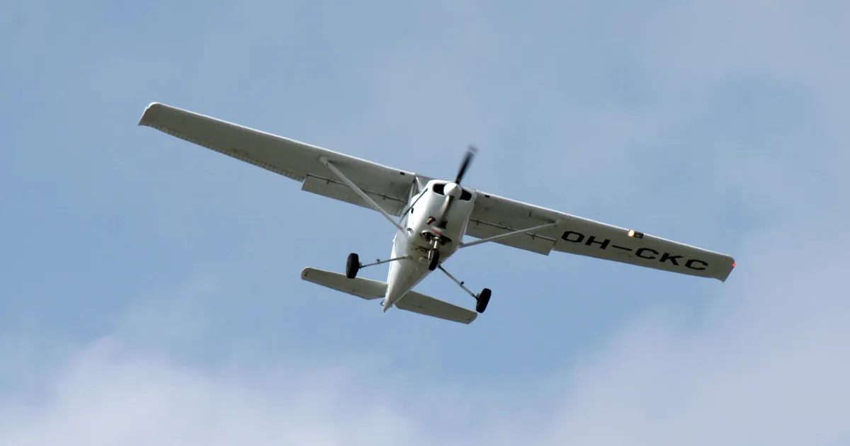
The Cessna Model 150 and F150-Series aircraft are high-wing monoplanes constructed with all-metal, semimonocoque design. They feature a fixed tricycle landing gear and are powered by a four-cylinder, horizontally opposed, air-cooled Continental or Rolls Royce engine. The manual details the structural specifications and operational characteristics of these aircraft.
Ground Handling, Servicing, Lubrication and Inspection
This section outlines procedures for ground handling, including towing, hoisting, and jacking. It emphasizes the importance of proper techniques to avoid damage during ground operations. Additionally, it covers routine servicing tasks such as fuel and oil checks, tire maintenance, and cleaning procedures to ensure the aircraft remains in optimal condition.
Aircraft Specifications
The manual provides detailed specifications for the Cessna 150, including gross weight, fuel capacity, oil capacity, and tire pressures. For instance, the maximum gross weight is 1600 lb, with a standard fuel capacity of 26 gallons. The specifications are crucial for understanding the aircraft's performance and operational limits.
Torque Values
A comprehensive chart of recommended nut torque values is included, specifying torque for various sizes and types of fasteners used in the aircraft. This information is vital for ensuring that components are securely fastened during maintenance.
Inspection Procedures
The manual details inspection procedures necessary for maintaining airworthiness. This includes pre-flight inspections, routine checks during storage, and specific inspections after extended periods of inactivity.
Safety notes
- Caution against turning the nose wheel more than 30 degrees to avoid damage.
- Do not set parking brakes during cold weather when moisture may freeze.
Full document text
150 SERIES 1969 THRU 1976 SERVICE MANUAL 0971 C3-13-RAND-1600-7175 LATEST CHANGED PAGES SUPERSEDE THE SAME PAGES OF PREVIOUS DATE Insert changed pages into basic publilatian. Destroy superseded pages. 1 JULY 1972 CHANGE 3 15 JUNE 1975 INSERT LATEST CHANGED PAGES. DESTROY SUPERSEDED PAGES. LIST OF EFFECTIVE PAGES NOTE: The portion of the text affected by the changes is indicated by a vertical line in the outer margins of the page. Changes to illustrations are indicated by miniature pointing hands. Dates of issue for original and changed pages are: Original. .0 . 1 July 1972 Change .1 1 June 1973 Change .2 1 July 1974 Change .3 15 June 1975 TOTAL NUMBER OF PAGES IN THIS PUBLICATION IS 346, CONSISTING OF THE FOLLOWING- Page Change Page Change Page Change No. No. No. No. No. No. *Title 3 *5-17 3 14-2 thru 14-3 1 *A. 3 5-18 1 14-4 0 i 1 *5-19 thru 5-25 3 15-1 1 *ii . 3 5-26 thru 5-27 0 *15-2 3 iii 0 *5-28. 3 *15-2A . 3 iv Blank . 0 6-1 thru 6-2 0 *15-2B Blank 3 1-1 0 *6-3 3 *15-3 3 *1-2 thru 1-4 3 6-4 0 15-4 thru 15-5 0 1-5 . 2 *6-5 . 3 *15-6 3 1-6 Blank 2 6-6 thru 6-7 0 15-7 thru 15-8 0 2-1 0 6-8 Blank 0 15-9 2 2-2 2 7-1 thru 7-9 1 15-10 thru 15-12 0 2-2A 2 7-10 thru 7-11 2 *15-13 . 3 2-2B Blank 2 7 -12 Blank. 2 15-14 . 2 2-3 1 *8-1 3 15-15 thru 15-17 1 2-4 2 8-2 0 15-18 thru 15-20 0 2-5 . 1 *8-3 thru 8-6 3 15-21 thru 15-22 2 *2-6 thru 2-7 3 *9-1 thru 9-4 3 *16-1 3 2-8 0 *9-4A 3 16-2 1 *2-9 thru 2-11 3 *9-4B Blank 3 16-3 2 2-12 1 *9- 5 thru 9-6 3 16-4 thru 16-5 1 *2-13 thru 2-14 3 10-1 2 16-6 0 2-15 2 *10-2 3 *16-7 3 *2-16 thru 2-17 3 *10-2A . 3 16-8 thru 16-11 0 2-18 thru 2-19 1 *10-2B Blank 3 *16-12 thru 16-14 3 2-20 2 10-3 0 16-15 . 1 2-21 thru 2-24 1 10-4 2 *16-16 3 *2-25 3 10-5 thru 10-6 1 16-16A 1 *2-26 Blank 3 *11-1 thru 11-3 3 16-16B Blank 1 *3-1 3 11-4 thru 11-10 0 16-17 thru 16-19 1 3-2 0 *11-11 thru 11-12 3 16-19A thru 16-19B. 1 *3-3 3 11-13 thru 11-16 0 16-20 thru 16-22 1 3-4 thru 3-5 2 11-17 1 16-23 2 *3-6 thru 3-15 3 11-18 thru 11-21 0 *16-24 . 3 *3-16 Blank 3 11-22 1 16-25 thru 16-26 0 4-1 0 11-22A 1 *16-26A 3 *4-2 3 11-22B Blank 1 *16-26B Blank 3 4-3 2 11-23 . 1 16-27 2 *4-4 thru 4-6 3 11-24 thru 11-25 0 16-28 thru 16-30 0 4-7 2 11-26 Blank 0 *16-31 thru 16-36 3 4-8 Blank 2 *12-1 3 *18-1 thru 18-2 3 *5-1 thru 5-3 3 12-2 0 18-3 thru 18-4 0 5-4 0 12-3 2 18-5 thru 18-6 2 *5-5 thru 5-6 3 12-4 1 *18-7 3 5-7 1 12-5 thru 12-7 2 18-8 thru 18-11. 0 5-8 2 12-8 1 18-12 1 *5-6A thru 5-8B 3 12-9 0 18-13 thru 18-33 0 *5-9 thru 5-11. 3 12-10 Blank 0 18-34 Blank 0 5-12 1 *13-1 3 *19-1 thru 19-2 3 *5-13 3 13-2 1 *20-1 thru 20-61 3 5-14 1 *13-3 thru 13-4 3 *20-62 Blank 3 5-15 thru 5-16 0 14-1 0 Upon receipt of the second and subsequent changes to this book, personnel responsible for maintaining this publication in current status should ascertain that all previous changes have been received and incorporated . • The asterisk indicates pages changed. added or deleted by the current change. A Change 3 TABLE OF CONTENTS SECTION Page 1 GENERAL DESCRIPTION . . . . . . . . . . . ......... 1-1 2 GROUND HANDLING, SERVICING, LUBRICATION AND INSPEC TION 2-1 3 FUSELAGE .... 3-1 4 WINGS AND EMPENNAGE 4-1 5 LANDING GEAR AND BRAKES 5-1 6 AILERON CONTROL SYSTEM 6-1 7 WING FLAP CONTROL SYSTEM 7-1 8 ELEVATOR CONTROL SYSTEM 8-1 9 ELEVATOR TRIM TAB CONTROL SYSTEM 9-1 10 RUDDER CONTROL SYSTEM . 10-1 11 ENGINE .. 11-1 12 FUEL SYSTEM 12-1 13 PROPELLER. 13-1 14 UTILITY SYSTEMS 14-1 •15 INSTRUMENTS AND INSTRUMENT SYSTEMS. 15-1 16 E LEC TRICAL SYSTEMS . . ....... 16-1 17 ELECTRONIC SYSTEMS (DELETED) (See page iii) 18 STRUCTURAL REPAffi 18-1 19 PAINTING .... 19-1 20 WffiING DIAGRAMS 20-1 Change 1 I I I I I CROSS REFERENCE LISTING OF POPULAR NAME VS. MODEL NUMBERS AND SERIALS All aircraft, regardless of manufacturer, are certificated under model number designations. However, popular names are often used for marketing purposes. To provide a consistent method of referring to the various aircraft, model numbers will be used in this publication unless names are required to differentiate between versions of the same basic model. The following table provides a cross reference listing of popular name vs. model numbers. MODEL SERIALS POPULAR NAME YEAR MODEL BEGINNING ENDING 150 STANDARD 1969 150J 15069309 15071128 150 TRAINER, or 1970 150K 15071129 15072003 150 COMMUTER 1971 150L 15072004 15072628 1972 150L 15072629 15073661 1973 150L 15073662 15074850 1974 150L 15074851 15075781 150 STANDARD 1975 150M 15075782 15077005 150 COMMUTER 150 COMMUTER II 150 COMMUTER 1976 150M 15077006 150 COMMUTER II REIMS 150 1969 F150J F15000390 F15000529 REIMS/CESSNA F150 1970 F150K F15000530 F15000658 1971 F150L F15000659 F15000738 1972 F150L F15000739 F15000863 1973 F150L F15000864 F15001013 1974 F150L F15001014 F15001143 REIMS/CESSNA F150 1975 F150M F15001144 F15001248 REIMS/CESSNA F150 COM- 1976 F150M F15001249 MUTER 150 AEROBAT 1970 A150K A1500001 A1500226 1971 A150L A1500227 A1500276 1972 A150L A1500277 A1500339 1973 A150L A1500340 A1500430 1974 A150L A1500431 A1500523 1975 A150M A1500524 A1500609 1976 A150M A1500610 REIMS/CESSNA F150 AEROBAT 1970 FA150K FA1500001 FA1500081 1971 FA150L FA1500082 FA1500120 1972 FA150L FA1500121 FA1500166 1973 FA150L FA1500167 FA1500211 1974 FA150L FA1500212 FA1500261 1975 FA150M FA1500262 FA1500281 1976 FA150M FA1500282 ii Change 3 FOREWORD This manual contains factory-recommended procedures and in- structions for ground handling, servicing, and maintaining Cessna Model 150-Series aircraft. This includes the Models 150, Reims
Show full textShow less
150, Reims/Cessna F150, 150 Aerobat, and Reims/Cessna F150 Aerobat. The Reims versions of the Model 150 is identical to the Model 150 except that it is powered by a 0- 200-A Rolls Royce en- gine. Besides serving as a reference for the experienced mechanic, this book also covers step- by- step procedures for the less experi- enced man. This manual should be kept in a handy place for ready reference. If properly used, it will better enable the mechanic to maintain Cessna 150-Series aircraft and thereby establish a repu- tation for reliable service. The information in this manual is based on data available at the time of publication, and is supplemented and kept current by service letters and service news letters published by Cessna Aircraft Com- pany. These are sent to all Cessna Dealers so that they have the latest authoritative recommendations for servicing Cessna aircraft. Therefore, it is recommended that Cessna owners utilize the know- ledge and experience of the factory-trained Dealer Service Organi- zation. In addition to the information in this Service Manual, a group of vendor publications is available from the Cessna Service Parts Center, which describe complete disassembly, overhaUl, and parts breakdown of some of the various vendor equipment items. A list- ing of the available publications is issued periodically in service letters. Information for Nav-O-Matic Autopilots, Electronic Communi- cations, and Navigation Equipment are not included in this manual. These manuals are available from the Cessna Service Parts Center. iii/(iv blank) This page intentionally left blank. SECTION 1 GENERAL DESCRIPTION TABLE OF CONTENTS GENERAL DESCRIPTION Model 150 and Fl50-Series Description . . . . . Model A150 and FAl50-Series 1-1. GENERAL DESCRIPTION. 1-2. MODEL 150 AND FI50-SERIES. Page 1-1 1-1 1-1 1-1 1-3. DESCRIPTION. Cessna Model 150 and F150- Series aircraft, described in this manual, are high- wing monoplanes of all-metal, semimonocoque con- struction. These aircraft are equipped with a fixed tricycle landing gear. Through 1970 Models, they are equipped with flat spring-steel main landing gear struts and a steerable nose gear. Beginning with 1971 Models, these aircraft are equipped with tubu- lar spring-steel main gear struts and a steerable nose gear. The steerable nose gear is equipped with an air/hydraulic fluid shl .• strut. Two-place seat- ing is standard, and a double-width, fold-up auxiliary rear seat may be installed as optional equipment. Each Model 150 and Fl50-Series aircraft is equipped with a four-cylinder, horizontally opposed, air- cooled Continental or Rolls Royce engine, driving an all-metal, fixed-pitch propeller. These aircraft fea- ture a "wrap around" rear window and a swept-back fin and rudder. 1-4. MODEL A150 and FAI50-SERIES. 1-5. DESCRIPTION. Aerobatic Model A150 and F Al50-Series aircraft are a modification of the cur- rently produced Model 150. Structure has been Description . . . . . Aircraft SpeCifications Stations ... Torque Values . . . . 1-1 1-1 1-1 1-1 "beefed-up" in some areas in order to meet require- ments of the Acrobatic Category, FAR Part 23. In addition to the "beef-up", quick-release cabin doors, two-strap shoulder harnesses, and aerobatic paint design are standard. Only momentary inverted flight is approved, therefore no inverted system is offered, Removable seat and back cushions are provided to allow occupants to use either a seat-pack or back- pack type parachute during aerobatic maneuvers. 1-6. AIRCRAFT SPECIFICATIONS. Leading partic- ulars of these aircraft, with dimensions based on gross weight, are given in figure 1-1. If these di- mensions are used for constructing a hangar or com- puting clearances, remember that such factors as nose gear strut inflation, tire pressures, tire sizes, and load distribution may result in some dimensions that are considerably different from those listed. 1-7. STATIONS. Station diagrams are shown in fig- ures 1-2 and 1-3 to assist in locating equipment when a written description is inadequate or impractical. 1-8. TORQUE VALUES. A chart of recommended nut torque values is shown in figure 1-4. These tor- que values are recommended for all installation pro- cedures contained in this manual, except where other values are stipulated. They are not to be used for checking tightness of installed parts during service. 1-1 I GROSS WEIGHT . . . . FUEL CAPACITY Standard Wing (Total) Standard Wing (Usable) Long-Range Wing (Total) Long-Range Wing (Usable) . OIL CAPACITY Without External Filter . . With External Filter ENGINE MODEL (Refer to Section 11 for Engine Data) PROPELLER (Fixed Pitch) MAIN WHEEL TIRES .... . Pressure ....... . NOSE WHEEL TIRE (Standard) . Pressure ...... . NOSE WHEEL TIRE (Optional) . Pressure . . . . . . . . NOSE GEAR STRUT PRESSURE (Strut Extended) . WHEEL ALIGNMENT (Flat Spring Struts) Camber .......... . Toe-In .......... . WHEEL ALIGNMENT (Tubular Gear) Camber .•. Toe-In AILERON TRA VE L Up .... . Down ... . WING FLAP TRAVEL RUDDER TRAVEL (Measured parallel to water line) Right . . . . . . . . . . . . . . . . .. . Left .................. . RUDDER TRAVEL (Measured perpendicular to hinge line) Right . . . . . Left ..... ELEVATOR TRAVEL Up (Thru 1974) . Up (Beginning with 1975) Down ........ . ELEVATOR TRIM TAB TRAVEL Up ....... . Down .......... . PRINCIPAL DIMENSIONS Wing Span (Conventional Wing Tip) Wing Span (Conical-Camber Wing Tip) Length (With Large Spinner) (Thru 1970) Length (With Small Spinner) (Thru 1970) Length (With Large Spinner) (Beginning with 1971) Length (With Small Spinner) (Beginning with 1971) Fin Height (Maximum with Nose Gear Depressed and Flashing Beacon Installed on Fin (Thru 1974) . . . Fin Height (Maximum with Nose Gear Depressed and Flashing Beacon Installed on Fin) (Beginning with 1975). Track Width (Thru 1970). . . . . Track Width (Beginning with 1971) Tail Span ...... . BATTERY LOCATION ..... . Figure 1-1. Aircraft SpeCifications 1-2 Change 3 1600 lb 26 gal. 22.5 gal. 38 gal. 35 gal. 6 qt 7 qt CONTINENTAL 0-200 Series 69" McCAULEY 6.00 x 6, 4-Ply Rating 21 psi 5.00 x 5, 4-Ply Rating 30 psi 15 x 6.00 x 6, 4-Ply Rating 35 psi 20 psi 4 ° to 6° 0" to .06" 3° to 5° TUBULAR GEAR . 00" to +.16" NON-ADJUSTABLE 20°, +2° _0° 14°, +2° _0° 0° to 40° ±2 ° 20° 30', +0° _2° 20° 30', +0° _2° 23°, +0° _2° 23°, +0° _2° 25°±10 23°, +1° _0° 15 ° ±1 ° 32' 8-1/2" 33' 2" 23' 9" 23' 0" 23' 8-1/2" 23' 0" 8' 0" 8' 6" 6' 6-1/2" 7'7-1/4" 10' 0" Firewall . (Add 2" for optional strobe lights) 0.00 18.50 8.37 36.00 56.69 70.69 " " " " "" " I' II 11 II ~ 95.00 76.44 71. 44 49.69 Figure 1-2. Fuselage Stations 133.31 22.12 31. 75 44.12 102.00 120.00 Figure 1-3. Wing Stations 138.00 173.41 200.37 156.00 174.00 192.00 Change 3 1-3 RECOMMENDED NUT TORQUES THE TORQUE VALUES STATED ARE POUND-INCHES, RELATED ONLY TO STEEL NUTS ON OIL-FREE CADMIUM PLATED THREADS. FINE THREAD SERIES TENSION SHEAR TAP SIZE TORQUE TORQUE STD ALT STD ALT (NOTE 1) (NarE 2) (NarE 3) (NOTE 2) 8-36 12-15 7-9 10-32 20-25 20-28 12-15 12-19 1/4-28 50-70 50-75 30-40 30-48 5/16-24 100-140 100-150 60-85 60-106 3/8-24 160-190 160-260 95-110 95-170 7/16-20 450-500 450-560 270-300 270-390 1/2-20 480-690 480-730 290-410 290-500 9/16-18 800-1000 800-1070 480-600' 480-750 5/8-18 1100-1300 1100-1600 660-780 660-1060 3/4-16 2300-2500 2300-3350 1300-1500 1300-2200 7/8-14 2500-3000 2500-4650 1500-1800 1500-2900 1-14 3700-5500 3700-6650 2200-3300 2200-4400 1-1/8-12 5000-7000 5000-10000 3000-4200 3000-6300 1-1/4-12 9000-11000 9000-16700 5400-6600 5400-10000 COARSE THREAD SERIES (NarE 4) (NarE 5) 8-32 12-15 7-9 10-24 20-25 12-15 1/4-20 40-50 25-30 5/16-18 80-90 48-55 3/8-16 160-185 95-100 7/16-14 235-255 140-155 1/2-13 400-480 240-290 9/16-12 500-700 300-420 5/8-11 700-900 420-540 3/4-10 1150-1600 700-950 7/8-9 2200-3000 1300-1800 1-8 3700-5000 2200-3000 1-1/8-8 5500-6500 3300-4000 1-1/4-8 6500-8000 4000-5000 NOTES 1. Covers AN310, AN315, AN345, AN363, MS20365, MS21042, MS21044, MS21045 and MS21046. 2. When using AN310 or AN320 castellated nuts where alignment between the bolt and cotter pin slots is not reached using normal torque values, use alternate torque values or replace the nut. 3. Covers AN316, AN320, MS20364 and MS21245. 4. Covers AN363, MS20365, MS21042, MS21043, MS21044, MS21045 and MS21046. 5. Covers AN340. I~~~J)~N\ DO NOT REUSE SELF-LOCKING NUTS. The above values are recommended for all installation procedures contained in this manual, except where other values are stipulated. They are not to be used for checking tightness of installed parts during service. Figure 1-4. Torque Values 1-4 Change 3 RECOMMENDED NUT TORQUES THE TORQUE VALUES STATED ARE POUND-INCHES, RELATED IONLY TO STEEL NUTS ON OIL-FREE CADMIUM PLATED THREADS. FINE THREAD SERIES TENSION SHEAR TAP SIZE TORQUE TORQUE STD ALT STD ALT (NOTE 1) (NOTE 2) (NOTE 3) (NOTE 2) 8-36 12-15 7-9 10-32 20-25 20-28 12-15 12-19 1/4-28 50-70 50-75 30-40 30-48 5/16-24 100-140 100-150 60-85 60-106 3/8-24 160-190 160-260 95-110 95-170 7/16-20 450-500 450-560 270-300 270-390 1/2-20 480-690 480-730 290-410 290-500 9/16-18 800-1000 800-1070 480-600 480-750 5/8-18 1100-1300 1100-1600 660-780 660-1060 3/4-16 2300-2500 2300-3350 1300-1500 1300-2200 7/8-14 2500-3000 2500-4&50 1500-1800 1500-2900 1-14 3700-5500 3700-6650 2200-3300 2200-4400 1-1/8-12 5000-7000 5000-10000 3000-4200 3000-6300 1-1/4-12 9000-11000 9000-16700 5400-6600 5400-10000 COARSE THREAD SERIES (NOTE 4) (NOTE 5) 8-32 12-15 7-9 10-24 20-25 12-15 1/4-20 40-50 25-30 5/16-18 80-90 48-55 3/8-16 160-185 95-100 7/16-14 235-255 140-155 1/2-13 400-480 240-290 9/16-12 500-700 300-420 5/8-11 700-900 420-540 3/4-10 1150-1600 700-950 7/8-9 2200-3000 1300-1800 1-8 3700-5000 2200-3000 1-1/8-8 5500-6500 3300-4000 1-1/4-8 6500-8000 4000-5000 NOTES 1. Covers AN310, AN315, AN345, AN363, MS20365, MS21042, MS21044, MS21045 and MS21046. 2. When using AN310 or AN320 castellated nuts where alignment between the bolt and cotter pin slots is not reached using normal torque values, use alternate torque values or replace the nut. 3. Covers AN316, AN320, MS20364 and MS21245. 4. Covers AN363, MS20365, MS21042, MS21043, MS21044, MS21045 and MS21046. 5. Covers AN340. I~AU~I~NI DO NOT REUSE SELF-LOCKING NUTS. The above values are recommended for all installation procedures contained in this manual, except where other values are stipulated. They are not to be used for checking tightness of installed parts during service. Figure 1-4. Torque Values Change 2 1-5/(1-6 blank) This page intentionally left blank. SECTION 2 GROUND HANDLING, SERVICING, LUBRICATION AND INSPECTION TABLE OF CONTENTS GROUND HANDLING. Towing Hoisting. Jacking . Leveling. Parking . Tie-Down Flyable Storage Returning Aircraft to Service Temporary Storage ..... Inspection During Storage . . Returning Aircraft to Service Indefinite Storage. . . . . . Inspection During Storage . . Returning Aircraft to Service SERVICING Fuel Fuel Drains . . . . . . . . Carburetor Drain Plug Inspection Engine Oil ....... . Engine Induction Air Filter . . . . 2-1. GROUND HANDLING. Page 2-1 2-1 2-3 2-3 2-3 2-3 2-3 2-3 2-3 2-3 2-4 2-4 2-4 2-5 2-5 2-6 2-6 2-6 2-6 2-6 2-7 2-2. TOWING. Moving the aircraft by hand is ac- complished by using the wing struts and landing gear struts as push points. A tow bar attached to the nose gear should be used for steering and maneuvering the aircraft on the ground. When no tow bar is available, press down at the horizontal stabilizer front spar ad- jacent to the fuselage to raise the nose wheel off the ground. With the nose wheel clear of the ground, the aircraft can be turned by pivoting it about the main wheels. TOW BAR: PART NUMBER 0501019-1 IS AVAILABLE FROM THE CESSNA SERVICE PARTS CENTER. Vacuum System Filter Battery ...... . Tires ....... . Nose Gear Shock Strut Nose Gear Shimmy Dampener Hydraulic Brake Systems CLEANING ...... . Windshield and Windows. Plastic Trim. . . Painted Surfaces . . Aluminum Surfaces. Engine Compartment Upholstery and Interior Propeller ..... . Wheels ...... . LUBRICATION .... . Tachometer Drive Shaft Wheel Bearings Nose Gear Torque Links Wing Flap Actuator INSPECTION . . . . . . . ICAUTION\ When towing the aircraft, never turn the nose wheel more than 30 degrees either side of center or the nose gear will be damaged. Do not push on control surfaces or outboard em- pennage surfaces. When pushing on the tail- cone, always apply pressure at a bulkhead to avoid buckling the skin. NOTE Use tow bar carefully to avoid scarring finish on speed fairing. Figure 2-1. Tow Bar 2-8 2-8 2-8 2-9 2-9 2-9 2-9 2-9 2-9 2-9 2-13 2-13 2-13 2-13 2-13 2-13 2-13 2-13 2-13 2-13 2-18 2-1 REFER TO SHEET 2 FOR ITEM NUMBERS NOTE Corresponding points on both upper door sills may be used to level the aircraft laterally. Prior to 1971 Models, reference points for leveling the aircraft longitudinally are the top of the tailcone between rear window and vertical fin. Beginning with 1971 Models, reference points for longitudinal leveling of aircraft are two screws on left side of tailcone at zero waterline. These are indicated in illustration by A (Also refer to paragraph 2-5) REFER TO SHEET 2 FOR ITEM NUMBERS o 0 Figure 2-2. Jacking and Leveling (Sheet 1 of 2) 2-2 Change 2 JACKING INFORMATION ITEM NUMBER TYPE AND NUMBER REMARKS CD Block (Jack point not available) 1x4x4 padded with 1/4" rubber CD Jack Any short jack of capable capacity CD Universal tail stand Any tail stand of capable capacity CD Cessna #SE-576 (41-1/2" high) Universal jack stand (FOR USE WITH ITEM 2) CD Cessna #10004-98 Jack point * (SEE CAUTION) Cessna #0441215-1 Jack point # (SEE NOTE 5) Built-in jack pad Part of step bracket t CD #2-170 Basic jack Closed height: 69 1/2 inches; extended #2-70 Slide tube height: 92" (Insert slide tube extension (Use with item 1) into basic jack) 1. Wing jacks are placed under front spar of wing just outboard of wing strut, and must extend far enough to raise wheels off ground, and must be of adequate strength. 2. Attach a suitable stand to the tie-down ring. Be sure tail stand weighs enough to keep tail down and under all conditions that it is strong enough to support any weight that might be placed on it (place shot bags or sand bags on tail stand. In addition, the base of adjustable tail stand is to be filled with concrete for additional weight as a safety factor. 3. Operate jacks evenly until desired height is reached. When using universal jack point (10004-98), flexibility of the gear strut will cause the main wheel to slide inboard as the wheel is raised, tilting the jack. The jack must be lowered for a second operation. Jacking both wheels simultaneously with universal jack points is not recommended. Universal jack point may be used to raise only one main wheel. DO NOT USE brake casting as a jack point. 4. Items (4), (5) and (6) are available from the Cessna Service Parts Center. 5. On tubular gear aircraft, the only fairing requiring removal is the fuselage-to-tube gear fairing. Jack pad is inserted on tube in area between fuselage and upper end of tube fairing, then jack aircraft as required. * Thru Serials 15072003, A15000276, F15000658 and FA1500081. # Serials 15073004 thru 15073284, A15000277 thru A15000324, F15.000659 thru F15000833 and FA1500082 thru FA15000166. t Beginning with Serials 15073285, A15000325, F15000834 and FA15000167. Figure 2-2. Jacking and Leveling (Sheet 2 of 2) Change 2 2-2A/(2-2B blank) This page intentionally left blank. 2-3. HOISTING. The aircraft may be lifted with a hoist of two-ton capacity by using hOisting rings, which are optional equipment, or by means of suit- able slings. The front sling should be hooked to each upper engine mount at the firewall, and the aft sling should be positioned around the fuselage at the first bulkhead forward of the leading edge of the stabilizer. If the optional hoisting rings are used, a minimum cable length of 60 inches for each cable is required to prevent bending of the eyebolt-type hoisting rings. If deSired, a spreader jig may be fabricated to apply vertical force to the eyebolts. 2-4. JACKING. Refer to figure 2-2 for jacking procedures. 2-5. LEVELING. Corresponding pOints on both upper door sills may be used to level the aircraft laterally. Prior to the 1971 models, the reference point for leveling the aircraft longitudinally is the top of the tail cone between the rear window and vertical fin. Beginning with the 1971 models, the reference points for longitudinal leveling of the aircraft are the two screws on the left side of the tailcone at zero waterline. 2-6. PARKING. Parking precautions depend prin- cipally on local conditions. As a general precaution, set parking brake or chock the wheels and install the controls lock. In severe weather and high wind con- ditions, tie down the aircraft as outlined in paragraph 2-7 if a hangar is not available. 2-7. TIE-DOWN. When mooring the aircraft in the open, head into the wind if possible. Secure control surfaces with the internal control lock and set brakes. ICAUTION! Do not set parking brakes during cold weather when accumulated moisture may freeze the brakes or when the brakes are overheated. After completing the preceding, proceed to moor the aircraft as follows: a. Tie ropes, cables, or chains to the wing tie- down fittings located at the upper end of each wing strut. Secure the opposite ends of ropes, cables, or chains to ground anchors. b. Secure a tie-down rope (no chains or cables) to the exposed portion of the engine mount and secure opposite end of rope to a ground anchor. c. Secure the middle of a rope to the tail tie-down ring. Pull each end of rope away at a 45 degree angle and secure to ground anchors at each side of tail. d. Secure control lock on pilot control column. If control lock is not available, tie pilot control wheel back with front seat belt. e. These aircraft are equipped with a spring-loaded steering system which affords protection against nor- mal wind gusts. However, if extremely high wind gusts are antiCipated, additional external locks may be installed. 2-8. FLYABLE STORAGE. Flyable storage is de- fined as a maximum of 30 days non-operational stor- age and/or the first 25 hours of intermittent engine operation. NOTE The aircraft is delivered from Cessna with a Corrosion Preventive Aircraft Engine Oil (MIL-C-6529, Type II, RUST BAN). This engine oil is a blend of aviation grade straight mineral oil and a corrosion pre- ventive compound. This engine oil should be used for the first 50 hours of engine opera- tion. In the event it is necessary to add oil during the first 25 hours of operation, use only aviation grade straight mineral oil of the correct viscosity. • During the 30 day non-operational storage or the first 25 hours of intermittent engine operation, every sev- enth day the propeller shall be rotated through five revolutions, without running the engine. If the air- craft is stored outside, tie-down in accordance with paragraph 2-7. In addition, the pitot tube, static air-. vents, air vents, openings in the engine cowling, and other similar openings shall have protective covers installed to prevent entry of foreign material. After 30 days, aircraft Should be flown for 30 minutes or ground run-up until oil has reached operating temper- ature. 2-9. RETURNING AIRCRAFT TO SERVICE. After flyable storage, returning the aircraft to service is accomplished by performing a thorough pre-flight in- spection. At the end of the first 25 hours of engine operation, drain engine oil, clean oil screens and change external oil filter element. Service engine with correct grade and quantity of engine oil. Refer to figure 2-4 and paragraph 2-21 for correct grade of engine oil. 2-10. TEMPORARY STORAGE. Temporary storage is defined as aircraft in a non-operational status for a maximum of 90 days. The aircraft is constructed of corrosion resistant alclad aluminum, which will last indefinitely under normal conditions if kept clean, however, these alloys are subject to oxidation. The first indication of corrosion on unpainted surfaces is in the form of white deposits or spots. On painted surfaces, the paint is discolored or blistered. Stor- age in a dry hangar is essential to good preservation and should be procured if possible. Varying condi- tions will alter the measures of preservation, but under normal conditions in a dry hangar, and for storage periods not to exceed 90 days, the following methods of treatment are suggested: a. Fill fuel tanks with correct grade of gasoline. b. Clean and wax aircraft thoroughly. c. Clean any oil or grease from tires and coat tires with a tire preservative. Cover tires to pro- tect against grease and oil. d. Either block up fuselage to relieve pressure on tires or rotate wheels every 30 days to change sup- porting points and prevent flat spotting the tires. e. Lubricate all airframe items and seal or cover all openings which could allow moisture and/or dust to enter. Change 1 2-3 I NOTE The aircraft battery serial number is recorded in the aircraft equipment list. To assure ac- curate warranty records, the battery should be re-installed in the same aircraft from which it was removed. If the battery is returned to service in a different aircraft, appropriate record changes must be made and notification sent to the Cessna Claims Departmento f. Remove battery and store in a cool dry place; service the battery periodically and charge as re- quired. NOTE An engine treated in accordance with the fol- lowing may be considered protected against normal atmospheric corrosion for a period not to exceed 90 days. go Disconnect spark plug leads and remove upper and lower spark plugs from each cylinder. NOTE The preservative oil must be Lubricating Oil- Contact and Volatile, Corrosion Inhibited, MIL-L-46002, Grade 1 or equivalent. The following oils are approved for spraying op- erations by Teledyne Continental Motor s, Nucle Oil 105 - Daubert Chemical Co., 4700 So. Central Ave., Chicago, illinois, Petratect VA - Pennsylvania Refining Co., Butler Penn- sylvania. Ferro-Gard 1009G - Ranco Labora- tories, Inc., 3617 Brownsville Rd., Pittsburgh, Pennsyl vania. h. USing a portable pressure sprayer, atomize spray preservative oil through the upper spark plug hole of each cylinder with the piston in a down pOSi- tion. Rotate crankshaft as each pair of cylinders is sprayed. i. After completing step "h, " rotate crankshaft so that no piston is at a top pOSition. If the aircraft is to be stored outside, stop two-bladed propeller so that blades are as near horizontal as possible to pro- vide maximum clearance with passing aircraft. j. Again spray each cylinder without moving the crankshaft to thoroughly cover all interior surfaces of the cylinder above the piston. k. Install spark plugs and connect spark plug leads. 1. Apply preservative oil to the engine interior by spraying approximately two ounces of the preserva- tive oil through the oil filler tube. m. Seal all engine openings exposed to the atmos- phere using suitable plugs or non-hygroscopic tape. Attach a red streamer at each point that a plug or tape is installed. n. If the aircraft is to be stored outSide, perform the procedures outlined in paragraph 2-7. In addi- tion, the pitot tube, static source vents, air vents, openings in the engine cowling and other similar 2-4 Change 2 openings should have protective covers installed to prevent entry of foreign material. o. Attach a warning placard to the propeller to the effect that the propeller shall not be moved while the engine is in storage. 2-11. INSPECTION DURING STORAGE. a. Inspect airframe for corrosion at least once a month and remove dust collections as frequently as possible. Clean and wax as required. b. Inspect the interior of at least one cylinder through the spark plug hole for corrosion at least once a month. NOTE Do not move crankshaft when inspecting in- terior of cylinder for corrosion. c. If at the end of the 90 day period, the aircraft is to be continued in non-operational storage, again per- form the procedural steps fIg thru 0" of paragraph 2-10. 2-12. RETURNING AIRCRAFT TO SERVICE. After temporary storage, use the following procedures to return the aircraft to service. a. Remove aircraft from blocks and check tires for proper inflation. Check for proper nose gear strut inflation. b. Check battery and install. c. Check that oil sump has proper grade and quantity of engine oil. d. Service induction air filter and remove warning placard from propeller. e. Remove materials used to cover openings. f. Remove, clean, and gap spark plugs. g. While spark plugs are removed, rotate propeller several revolutions to clear excess rust preventive oil from cylinders. ho Install spark plugs. Torque spark plugs to 330 ±30 lb-in and connect spark plug leads. i. Check fuel strainer. Remove and clean filter screen if necessary. Check fuel tanks and fuel lines for moisture and sediment, drain enough fuel to elimi- nate moisture and sediment. j. Perform a thorough pre-flight inspection, then start and warm-up engine. 2-13. INDEFINITE STORAGE. Indefinite storage is defined as aircraft in a non-operational status for an indefinite period of time. Engines treated in accor- dance with the following may be considered protected against normal atmosphere corrOSion, provided the procedures outlined in paragraph 2-14 are performed at the intervals speCified. a. Operate engine until oil temperature reaches normal operating range. Drain engine oil sump and reinstall drain plug. b. Fill oil sump to normal operating capacity with corrosion preventive mixture which has been thor- oughly mixed and pre-heated to a minimum of 221°F at the time it is added to the engineo NOTE Corrosion preventive mixture consists of one part compound MIL-C-6529, Type I, mixed with three parts new lubricating oil of the grade recommended for service. Continental Motors Corporation recommends Cosmoline No. 1223, supplied by E. F. Houghton & Co., 305 W. LeHigh Avenue, Philadelphia, Pa. During all spraying operation corrosion mix- ture is pre - heated to 221 ° to 250 ° F . c. Immediately after filling the oil sump with cor- rosion preventive mixture, fly the aircraft for a period of time not to exceed a maximum of 30 min- utes. d. With engine operating at 1200 to 1500 rpm and induction air filter removed, spray corrosion pre- ventive mixture into induction air box, at the rate of one-half gallon per minute, until heavy smoke comes from exhaust stack, then increase the spray until the engine is stopped. ICAUTION\ Injecting corrosion-preventive mixture too fast can cause a hydrostatic lock. e. Do not rotate propeller after completing step "d." f. Remove all spark plugs and spray corrosion- preventive mixture, which has been pre-heated to 221 ° to 250°F, into all spark plug holes to thorough- ly cover interior surfaces of cylinders. g. Install lower spark plug or install solid plugs, and install dehydrator plugs in upper spark plug holes. Be sure that dehydrator plugs are blue in color when installed. h. Cover spark plug lead terminals with shipping plugs (AN4060-1) or other suitable covers. i. With throttle in full open position, place a bag of desiccant in the carburetor intake and seal open- ing with moisture resistant paper and tape. j. Place a bag of desiccant in the exhaust tail- pipe(s) and seal openings with moisture resistant tape. k. Seal cold air inlet to the heater muff with mois- ture resistant tape. 1. Seal engine breather by inserting a protex plug in the breather hose and clamping in place. m. Seal all other engine openings exposed to atmos- phere using suitable plugs or non-hygroscopic tape. NOTE Attach a red streamer to each place plugs or tape is installed. Either attach red streamers outside of the sealed area with tape or to the inside of the sealed area with safety wire to prevent wicking of moisture into the sealed area. n. Drain corrosion-preventive mixture from engine sump and reinstall drain plug. NOTE The corrosion-preventive mixture is harmful to paint and should be wiped from painted sur- faces immediately. o. Attach a warning placard on the throttle control knob, to the effect that the engine contains no lubri- cating oil. Placard the propeller to the effect that it should not be moved while the engine is in storage. p. Prepare airframe for storage as outlined in paragraph 2-10 thru step Iff. " • NOTE As an alternate method of indefinite storage, the aircraft may be serviced in accordance with paragraph 2-10 providing the aircraft is run-up at maximum intervals of 60 days and then reserviced per paragraph 2-10. 2-14. INSPECTION DURING STORAGE. Aircraft in indefinite storage shall be inspected as follows: a. Inspect cylinder protex plugs each 7 days. b. Change protex plugs if their color indicates an unsafe condition. c. If the dehydrator plugs have changed color in one half of the cylinders, all desiccant material in the engine shall be replaced with new material. d. Every 6 months respray the cylinder interiors with corrosion-preventive mixture. NOTE Before spraying, inspect the interior of one cylinder for corrosion through the spark plug hole and remove at least one rocker box cover and inspect the valve mechanism. 2-15. RETURNING AmCRAFT TO SERVICE. After indefinite storage, use the following procedure to return the aircraft to service. a. Remove aircraft from blocks and check tires for correct inflation. Check for correct nose gear strut inflation. b. Check battery and install. c. Remove all materials used to seal and cover openings. d. Remove warning placards posted at throttle and propeller. e. Remove and clean engine oil screen, then re- install and safety. On aircraft that are equipped with an external oil filter, install new filter element. f. Remove oil sump drain plug and drain sump. Install and safety drain plug. NOTE The corrosion-preventive mixture will mix with the engine lubricating oil, so flushing the oil system is not necessary. Draining the oil sump will remove enough of the cor- rosion-preventive mixture. Change 1 2-5 g. Service and install the induction air filter. h. Remove dehydrator plugs and spark plugs or plugs installed in spark plug holes and rotate pro- peller by hand several revolutions to clear corrosion- preventive mixture from cylinders. i. Clean, gap, and install spark plugs. Torque plugs to the value listed in Section 11. j. Check fuel strainer. Remove and clean filter screen. Check fuel tanks and fuel lines for moisture and sediment, and drain enough fuel to eliminate. k. Perform a thorough pre-flight inspection, then start and warm-up engine. I. Thoroughly clean aircraft and flight test air- craft. 2-16. SERVICING. 2 -17. Servicing requirements are shown in figure 2-4. The following paragraphs supplement this figure by adding details not included in the figure. 2-18. FUEL. Fuel tanks should be filled immedi- ately after flight to lessen moisture condensation. Tank capacities are listed in Section 1. The recom- mended fuel grade to be used is given in figure 2-4. 2-19. FUEL DRAINS are located in the fuel tanks, fuel line, fuel strainer, and carburetor. Drain plugs are installed in the fuel tanks, fuel line forward of ON-OFF valve, and carburetor. The strainer drain valve is an integral part of the fuel strainer assembly. The strainer drain is equipped with a control which is located adjacent to the oil dipstick. Access to the control is through the oil dipstick access door. Re- move drain plugs and open strainer drain at the in- tervals specified in figure 2-4. Also, during daily inspection of the fuel strainer, if water is found in the fuel strainer, there is a possibility that the wing tank sumps or fuel line contain water. Therefore, all fuel drain plugs should be removed and all water drained from the system. To activate drain valve for fuel sampling, place cup up to valve and depress valve with rod protruding from cup. See figure 12 -3. 2-20. CARBURETOR DRAIN PLUG INSPECTION. In order to prevent the possibility of thread sealant contamination in the carburetor float chamber, cleaning and inspection of the carburetor should be accomplished at each 100-hour inspection and any- time water in the fuel is suspected. a, With the fuel valve OFF, remove carburetor drain plug and clean off any sealant present on the end of the plug or in the threads on the plug. b, Inspect drain plug hole in the carburetor and re- move any sealant remaining in the hole, c. Turn fuel valve to ON to flush float chamber and drain plug chamber while probing drain plug hole to ascertain that all residue of sealant material is dis- lodged and washed out of the chamber. Flushing operation should last 15 to 30 seconds. d, A second flushing should then be accomplished and the drained fuel retained for inspection to insure that no sealant particles are present. e. Install drain plug as follows: 1. Install drain plug in carburetor 1-1/2 to 2 turns. 2. Apply sealant to drain plug threads (use 2-6 Change 3 NS-40 (RAS-4) or equivalent). I 3, Tighten and safety drain plug. f. Turn fuel valve ON and inspect for evidence of fuel leakage. 2 -21. ENGINE OIL. Check engine lubricating oil with the oil dipstick five to ten minutes after the en- gine has been stopped. Engine oil should be drained while the engine is still hot so that more positive draining is obtained. Refer to the inspection charts for required intervals for oil and filter changes. Change oil every 6 months even though less than the specified hours have accumulated. Reduce these peri- ods for prolonged operation in dusty areas, in cold climate where sludging conditions exist, or where short flights and long idle periods are encountered, which cause sludging conditions. Always change oil and install a new filter element or clean screens whenever oil on dipstick appears dirty. NOTE On aircraft equipped with an oil cooler, drain oil cooler at each oil change period. When oil cooler is drained and after the first engine run-up, check oil with dipstick and add oil as required to bring oil in the sump to the desired leveL Oil capacity is six quarts total with a normal oper- ating capacity of five quarts for flights of less than three hours, For extended flight, fill to the six quart level on the dipstick, DO NOT operate with less than the minimum for flight quantity of four quarts. If the engine is equipped with an external oil filter, an additional quart of oil is required when the filter element is changed. When adding or chang- ing engine oil, use aviation grade oil in accordance with figure 2-4. NOTE New or newly-overhauled engines should be operated on aviation grade straight mineral oil until the first oil change. If an ashless Idispersant oil is used in a new or newly-over- hauled engine, high oil consumption may be experienced. The anti-friction additives in ashless dispersant oils will retard "break- • in" of the piston, rings and cylinder walls. This condition can be avoided by the use of straight mineral oil. The aircraft is delivered from Cessna with a Corrosion Preventive Air- craft Engine Oil (MIL-C -6529, Type IT, RUST BAN). If oil must be added during the first 25 hours, use only aviation grade straight mineral oil (non-detergent) conforming to Specification No. MIL-L-6082. After the first 25 hours of operation, drain engine oil sump and clean both the oil suction strainer and oil pressure screen. If an optional oil filter is installed, change fil- ter element at this time. Refill sump with straight mineral oil (non-detergent) and use until a total of 50 hours have accumulated or oil consumption has stabilized, then change to ashless dispersant oil, conforming with IContinental Motors Specification MHS-24 and revisions and supplements thereto and with current Continental Aircraft Engine Service Bulletins. Ashless dispersant oil, conforming with Continental Motors SpeCification MHS-24 and revisions and sup- plements thereto and with current Continental Air- craft Engine Service Bulletins, must be used at the oil change after 50 hours of operation. When chang- ing engine oil, remove and clean oil screens, or in- stall a new filter element on aircraft equipped with an external oil filter. An oil quick-drain valve may be installed. This valve provides a quick and clean- er method of draining the engine oil. The valve is installed in the oil drain port of the oil sump and al- lows the oil to be drained by inserting a hose over the fitting end and pushing up to lock the valve open, causing the oil to drain through the hose into a con- tainer. To drain the engine oil, proceed as follows: a. Operate engine until oil temperature is a normal operating temperature. b. (With Quick-Drain Valve.) Attach a hose to the quick-drain valve in the oil sump. Push up on quick-drain valve until it locks open, and allow oil to drain through hose into container. c. (Without Quick-Drain Valve.) Remove oil drain plug from oil sump and allow oil to drain into a container. d. After engine oil has drained, close quick- drain valve and remove hose, or install and safety drain plug. e. Remove and clean oil screens, or change external oil filter element. f. On aircraft equipped with an oil cooler, re- move cooler drain plug and drain oil cooler at each oil change. After oil cooler has drained, install and safety drain plug. g. Service engine with correct quantity and grade of engine oil. (See figure 2-4). NOTE When oil cooler is drained or external filter element is changed and after the first engine run-up, check oil with dip- stick and add oil as required to bring oil in the sump to the desired level. 2-22. ENGINE INDUCTION AIR FILTER. The in- duction air filter keeps dust and dirt from entering the induction system. The value of maintaining the air filter in a good clean condition can never be over- stressed. More engine wear is caused through the use of dirty or damaged air filter than is generally believed. The frequency with which the filter should be removed, inspected, and cleaned will be deter- mined primarily by aircraft operating conditions. A good general rule however, is to remove, inspect and clean the filter at least every 50 hours of engine op- erating time and more frequently if warranted by op- erating conditions. Some operators prefer to hold a spare induction air filter at their home base of opera- tion so that a clean filter is always readily available for use. Under extremely dusty conditions, daily servicing of the filter is recommendedo Two types of filters are used. One is a flock-coated, oiled filter and the other is a dry, paper -media filter. NOTE The aircraft is equipped with the flock-coated, oiled filter when it leaves the factory. How- ever, new filters ordered from the Cessna Service Parts Center will be the dry, paper- media filter with an improved element. To service the flock-coated, oiled filter, proceed as follows: a. Remove filter from aircraft. b. Wash filter thoroughly in solvent (Federal Speci- fication P-S-661 or equivalent). Wash with soiled face down in solvent. co Drain and dry filter, then dip flock-coated screen filter in the same grade of oil used in the engine and allow excess oil to drain from the filter. d. Be sure air box is cleaned, inspect filteL If filter is damaged, install a new filter. NOTE A damaged filter may have broken filtering panels or the flock coating may be miSSing from the filtering panels, which will allow unfiltered air to enter the induction system. Any filter that appears doubtful, shall have a new filter installed in its place. e. Install filter at entrance to air box with gasket on aft face of filter frame and with air flow arrow on filter pointed in the correct direction. To service the dry type filter, proceed as follows: a. Remove filter from aircraft. NOTE Use care to prevent damage to filter element when cleaning filter with compressed airo b. Clean filter by blowing with compressed air (not over 100 psi) from direction opposite of normal air flow. Arrows on filter case indicate direction of normal air flow. ICAUTION\ Do not use solvent or cleaning fluids to wash filter. Use only a water and household deter- gent solution when washing the filter. c. After cleaning as outlined in step "b", the filter may be washed, if necessary, in a solution of warm water and a mild household detergent. A cold water solution may be used. Change 3 2-7 NOTE The filter assembly may be cleaned with com- pressed air a maximum of 30 times or it may be washed a maximum of 20 times. A new filter should be installed after using 500 hours of engine operating time or one year, whichever should occur first. However, a new filter should be installed at anytime it is damaged. A damaged filter may have sharp or broken edges in the fil- tering panels which would allow unfiltered air to enter the induction system. Any filter that ap- pears doubtful, shall have a new filter installed in its place. d. After washing, rinse filter with clear water un- til rinse water draining from filter is clear. Allow water to drain from filter and dry with compressed air (not over 100 psi). NOTE The filtering panels of the filter may become distorted when wet, but they will return to their original shape when dry. e. Be sure air box is clean, inspec t filter. If fil- ter is damaged, install a new filter. f. Install filter at entrance to air box with gasket on aft face of filter frame and with air flow arrow on filter frame pointed in the correct direction. 2-23. VACUUM SYSTEM FILTER. The vacuum sys- tem central air filter keeps dust and dirt from enter- ing the vacuum operated instruments. Change central air filter element every 500 hours of operating time and whenever suction gage reading drops below 4.6 inches of mercury. Also, do not operate the vacuum system with the filter removed, or a vacumm line disconnected as particles of dust or other foreign matter may enter the system and damage the gyros. 2-24. BATTERY. Battery servicing involves adding distilled water to maintain the electrolyte level even with the horizontal baffle plate or split ring at the bot- tom of the filler holes, checking cable connections, and neutralizing and cleaning off any spilled electro- lyte or corrosion. Use bicarbonate of soda (baking soda) and clean water to neutralize electrolyte or corrosion. Follow with a thorough flushing with clean water. Do not allow bicarbonate of soda to en- ter battery. Brighten cable and terminal connec- tions with a wire brush, then coat with petroleum jelly before connecting cables, Check the battery every 50 hours (or at least every 30 days), oftener in hot weather. Add only distilled water, not acid or "rejuvenators", to maintain electrolyte level in the battery. Inspect the battery box and surrounding area and clean and remove any evidence of corrosion. Refer to Section 16 for detailed battery removal, in- stallation, and testing. 2-25. TIRES. Maintain tire pressure at the air pressure specified in figure 1-1. When checking tire pressure, examine tires for wear, cuts, bruises, and Slippage. Remove oil, grease and mud from tires with soap and water. Figure 2-3. Tie-Down Details 2-8 NOTE Recommended tire pressures should be main- tained. Especially in cold weather, remember that any drop in temperature of the air inside a tire causes a corresponding drop in air pres- sure. 2-26. NOSE GEAR SHOCK STRUT. The nose gear shock strut requires periodic checking to ascertain that the strut is filled with hydraulic fluid and is in- flated to the correct air pressure. To fill the nose gear strut with hydraulic fluid and inflate with air, proceed as follows: ' a. Remove filler valve cap and depress valve core to completely deflate nose strut. b. Remove filler valve from strut. c. With nose gear strut compressed to its shortest length, fill strut with hydraulic fluid to the bottom of the filler hole. d. Raise nose of aircraft, extend and compress strut several times to expel any entrapped air, then lower nose of aircraft and repeat step "c". e. With strut compressed to its shortest length, install filler valve assembly. f. With nose wheel off ground, inflate strut. Shock strut pressure is listed in figure 1-1. NOTE The nose landing gear shock strut will nor- mally require only a minimum amount of service. Maintain the strut extension pres- sure, as shown in figure 1-1. Lubricate landing gear as shown in figure 2-5. Check the landing gear daily for general cleanli- ness, security of mounting, and for hydrau- lic fluid leakage. Keep machined surfaces wiped free of dirt and dust, using a clean lint-free cloth saturated with MIL-H-5606 hydraulic fluid or kerosene. All surfaces should be wiped free of excessive hydraulic fluid. 2-27. NOSE GEAR SHIMMY DAMPENER. The shimmy dampener should be serviced at least every 150 hours. The shimmy dampener must be filled completely with flUid, free of entrapped air, to serve its purpose. To service the shimmy damp- ener, proceed as follows: a. Remove shimmy dampener from aircraft. b. While holding the dampener in a vertical posi- tion with fitting end pointed downward, pull fitting end of the dampener shaft to its limit of travel. c. While holding dampener in this position, fill dampener through open end of cylinder. d. Push the shaft upward slowly to seal off the fil- ler hole. e. Clean dampener with solvent. Be sure to keep the shaft protruding through the filler hole until dampener is installed on the aircraft. £. Install dampener on aircraft. NOTE Keep shimmy dampener, especially the ex- posed portions of the dampener piston shaft, clean to prevent collection of dust and grit which could cut the seals in the dampener barrel. Keep machined surfaces wiped free of dirt and dust, using a clean lint-free cloth saturated with MIL-H-5606 hydraulic fluid or kerosene. All surfaces should be wiped free of excessive hydraulic fluid. 2-28. HYDRAULIC BRAKE SYSTEMS. Check brake master cylinders and refill with hydraulic fluid as specified in the inspection charts. Bleed the brake system of entrapped air whenever there is a spongy response to the brake pedals. Refer to paragraph 5-58 for filling and bleeding the brake system. 2-29. CLEANING. 2-30. Keeping the aircraft clean is important. Be- sides maintaining the trim appearance of the aircraft, cleaning lessens the possibility of corrosion and makes inspection and maintenance easier. 2-31. WINDSHIELD AND WINDOWS should be cleaned carefully with plenty of fresh water and a mild detergent, using the palm of the hand to feel and dislodge any caked dirt or mud. A sponge, soft cloth, or chamois may be used, but only as a means of carrying water to the plastic. Rinse thoroughly, then dry with a clean moist chamois. Do not rub the plastiC with a dry cloth as this builds up an electro- static charge which attracts dust. Oil and grease may be removed by rubbing lightly with a soft cloth moistened with Stoddard solvent. I~AUTION\ Do not use gasoline, alcohol, benzene, acetone, carbon tetrachloride, fire extinguisher flUid, de-icer flUid, lacquer thinner, or glass window cleaning spray. These solvents will soften and craze the plastic. After washing, the plastic windshield and windows should be cleaned with an aircraft windshield cleaner. Apply the cleaner with soft cloths and rub with mod- erate pressure. Allow the cleaner to dry, then wipe it off with soft flannel cloths. A thin, even coat of wax, polished out by hand with soft flannel cloths, will fill in minor scratches and help prevent further scratching. Do not use a canvas cover on the wind- shield or windows unless freezing rain or sleet is anticipated since the cover may scratch the plastic surface. 2-32. PLASTIC TRIM. The instrument panel, plas- tic trim, and control knobs need only be wiped with a damp cloth. Oil and grease on the control wheel and control knobs can be removed with a cloth moist- ened with Stoddard solvent. Volatile solvents, such as mentioned in paragraph 2-31, must never be used since they soften and craze the plastic. 2-33. PAINTED SURFACES. The painted exterior surfaces of the aircraft, under normal conditions, require a minimum of polishing and buffing. Approxi- mately 15 days are required for acrylic or lacquer paint to cure completely; in most cases, the curing Change 3 2-9 ....... ............ . oil ...... .. ·.........,........ . HYDRAULIC FLUID: SPEC. NO. MIL-H-5606 RECOMMENDED FUEL: i~~Uj)ON\ • Compliance with conditions stated in Continental aircraft engine Service Bulletins M74-6 and M75-2 and sup- plements or revisions thereto, are recommended when using alternate fuel. FUEL: MINIMUM: 80/87 Aviation Grade .ALTERNATES: 1. 100/130 Low Lead Avgas (with lead content limited to a maximum of 2 cc Tetraethyllead per gallon) 2. 100/130 Higher Lead Avgas (with lead content lim- ited to a maximum of 4.6 cc Tetraethyllead per gallon) RECOMMENDED ENGINE OIL: AVIATION GRADE: ABOVE 40°F BELOW 40°F SAE 40 SAE 20 Aviation Grade ashless dispersant oil conforming to Continental Motors SpeCification MHS-24 and all revisions and supplements thereto must be used except as noted in paragraph 2 -21. Refer to Continental Aircraft Engine Service Bulletin M74-l9 and any superseding bulletins, revisions, or supplements thereto for further recommendations. Figure 2 -4. Servic ing (Sheet 1 of 3) 2-10 Change 3 o DAILY 3 FUE L TANK FILLER Service after each flight. Keep full to retard condensation. Refer to paragraph 2 -18 for details. 4 FUE L TANK SUMP DRAINS If quick-drain valves are installed, drain off any water and sediment before first flight of the day. 6 PITOT AND STATIC PORTS Check for obstructions before first flight of the day. 10 FUE L STRAINER Drain off any water and sediment before the first flight of the day. Refer to paragraph 2 -19 for details. 13 INDUCTION AIR FILTER Inspect and service under dusty conditions. Refer to paragraph 2 -22 for details. 16 OIL DIPSTICK 18 15, 17 Check oil on preflight. Add oil as necessary. Refer to paragraph 2-21 for details. OIL FILLER CAP: Whenever oil is added, check that filler cap is tight and oil filler door is secure. o FmST 25 HOURS ENGINE OIL SYSTEM Refill with straight mineral oil, non-detergent, and use until a total of 50 hours have accumulated or oil consumption has stabilized, then change to ashless dispersant oil. o 50HOURS 13 INDUCTION AIR FILTER Clean filter per paragraph 2-22. Replace as required. 14 BATTERY 15, 17 12 7 Check electrolyte level and clean battery compartment each 50 hours or each 30 days. ENGINE OIL SYSTEM Change oil each 50 hours if engine is NOT equipped with external oil filter; if equipped with external oil filter, change filter element each 50 hours and oil at each 100 hours, or every 6 months. SHIMMY DAMPENER Check fluid level and refill as required with hydraulic fluid. Refer to paragraph 2 -27 for details. TIRES Maintain correct tire inflation as listed in figure 1-1. Also refer to paragraph 2-25 for details. Figure 2-4. Servicing (Sheet 2 of 3) Change 3 2-11 I I I o 50 HOURS (Cont) 11 NOSE GEAR SHOCK STRVT Keep strut filled and inflate to correct pressure. Refer to paragraph 2-26 for details. o 100HOURS 5 SHUT-OFF VALVE DRAIN Remove plug and drain off any water or sediment. Also refer to paragraph 2-19. 10 FUEL STRAINER Disassemble and clean strainer bowl and screen. I0 I 200 HOURS VACUUM RELIEF FILTER Change each 1000 hours, or to coincide with engine overhauls. 4 FUEL TANK SUMP DRAINS 9 If quick-drain valves are not installed, remove plugs and drain off any water or sedi- ment. Reinstall plugs and safety. Also refer to paragraph 2-19. BRAKE MASTER CYLINDERS Check fluid level and refill as required with hydraulic fluid. Refer to paragraph 2-28 for details. o 500HOURS 2 VACUUM SYSTEM CENTRAL AIR FILTER Replace every 500 hours. 6. AS REQUIRED 8 GROUND SERVICE RECEPTACLE Connect to 12-volt DC, negative-ground power unit. Refer to Section 11 for details. Figure 2-4. Servicing (Sheet 3 of 3) 2-12 Change 1 period will have been completed prior to delivery of the aircraft. In the event that polishing or buffing is required within the curing period, it is recommended that the work be done by an experienced painter. Generally, the painted surfaces can be kept bright by washing with water and mild soap, followed by a rinse with water and drying with cloths or chamois. Harsh or abraSive soaps or detergents which could cause corrosion or make scratches should never be used. Remove stubborn oil and grease with a cloth moistened with Stoddard solvent. After the curing period, the aircraft may be waxed with a good auto- motive wax. A heavier coating of wax on the leading edges of the wing and tail and on the engine nose cap will help reduce the abrasion encountered in these areas. 1 2-34. ALUMINUM SURFACES. The aluminum sur- faces require a minimum of care, but should never be neglected. The aircraft may be washed with clean water to remove dirt and may be washed with non- alkaline grease solvents to remove oil and/or grease. Household type detergent soap powders are effective cleaners, but should be used cautiously since some of them are strongly alkaline. Many good aluminum cleaners, polishes, and waxes are available from commercial suppliers of aircraft products. 2-35. ENGINE AND ENGINE COMPARTMENT. The engine should be kept clean since dirty cooling fins and baffle plates can cause overheating of the engine. Also, cleaning is essential to minimize any danger of fire and provide for easier inspection of components. The entire engine cowling may be removed to facili- tate engine and interior cowl cleaning. Wash down the engine and components with a suitable solvent, such as Stoddard solvent or equivalent, then dry thor- oughly with compressed air. ICAUTION\ Particular care should be given to electrical equipment before cleaning. Solvent should not be allowed to enter magnetos, starters, alternators, voltage regulators, and the like. Hence, these components should be protected before saturating the engine with solvent. Any fuel, oil, and air openings should be covered before washing the engine with solvent. Caustic cleaning solutions should not be used. After cleaning engine re-lubricate all control arms and moving parts. 2-36. UPHOLSTERY AND INTERIOR. Keeping the upholstery and interior clean prolongs upholstery fab- ric and interior trim life. To clean the interior, pro- ceed as follows: a. Empty all ash trays and refuse containers. b. Brush or vacuum clean the upholstery and carpet to remove dust and dirt. c. Wipe leather and plastic trim with a damp cloth. d. Soiled upholstery fabrics and carpet may be cleaned with a foam-type detergent used according to the manufacturer's instructions. e. Oil spots and stains may be cleaned with house- hold spot removers, used sparingly. Before using any solvent, read the instructions on the container and test it on an obscure place in the fabric to be cleaned. Never saturate the fabric with volatile sol- vent; it may damage the padding and backing material. f. Scrape sticky material from fabric with a dull knife, then spot clean the area. 2-37. PROPELLER. Wash hub and blades with a soft cloth and Stoddard cleaning solvent or equivalent, then dry thoroughly with compressed air. The pro- peller should be wiped occasionally with an oily cloth, then wiped with a dry cloth. In salt water areas this will aSSist in corrosion proofing the propeller. 2 -38. WHEELS. The wheels should be washed periodically and examined for corrosion, chipped paint, and cracks or dents in the wheel halves or in the flanges or hubs. If defects are found remove and repair in accordance with Section 5. Discard cracked wheel halves, flanges or hubs and install new parts. 2-39. LUBRICATION. 2-40. Lubrication requirements are shown in figure 2-5. Before adding grease to grease fittings, wipe dirt from fitting. Lubricate until grease appears around parts being lubricated, and wipe excess grease from parts. The following paragraphs sup- plement figure 2-5 by adding details. 2-41. TACHOMETER DRIVE SHAFT. Refer to Section 15 for details on lubrication of shaft. 2-42. WHEEL BEARINGS. Clean and repack the wheel bearings at the first 100-hour inspection and at each 500-hour inspection thereafter. If more than the usual number of take-offs and landings are made, extensive taxiing is required, or the aircraft is operated in dusty areas or under seacoast condi- tions, cleaning and lubrication of the wheel bearings shall be accomplished at each 100-hour inspection. 2-43. NOSE GEAR TORQUE LINKS. Lubricate nose gear torque links every 50 hours. When operating in dusty conditions, more frequent lubrication is re- quired. 2 -44. WING FLAP AC TUA TOR. a. On aircraft prior to Serials 15072630, F15000739, A15000278 and FA15000133 not modified by Service Kit SK150-37B and SK150-41, proceed as follows: 1. At each 100 hour inspection, inspect wing flap actuator jack screw and ball retainer assembly for lubrication, and lubricate if required. Also, remove, clean and lubricate jack screw whenever actuator slip- page is experienced. If lubrication is required, pro- ceed as follows: a. Gain access to actuator by removing appro- priate inspection plates on lower surface of wing. b. Expose jack screw by operating flaps to full- down position. ' c. Wipe a small amount of lubricant from jack screw with a rag and examine for condition. Lubri- cant should not be dirty, sticky, gummy or frothy in appearance. d. Inspect wiped area on jack screw for presence of hard scale deposit. Previous wiping action will have exposed bare metal if no deposit is present. Change 3 2 -13 e. If any of the preceding conditions exist, clean and relubricate jack screw as outlined in steps "f" thru "r". f. Remove actuator from aircraft as outlined in Section 7. g. Remove all existing lubricant from jack screw and torque tube by running the nut assembly to the end of the jack screw away from the gearbox, and soaking the nut assembly and jack screw 'in Stoddard solvent. NOTE Care must be taken to prevent solvent from entering gearbox. The gearbox lubricant is not affected and should not be disturbed. h. After soaking, clean entire length of jack screw with a wire brush, rinse with solvent and dry with compressed air. NOTE Do not disassemble nut and ball retainer assembly. i. Relubricate jack screw with MIL-G-21164 (Molybdenum Disulfide Grease) as outlined in steps "j" thru "m". j. Rotate nut down screw toward the motor. k. Coat screw and thread end of nut with grease and run nut to full extension. 1. Repeat the process and pack lubricant in the cavity between the nut and ball retainer assembly at the threaded end of the nut. SHOP NOTES: 2-14 Change 3 m. Repeat the process and work nut back and forth several times. n. Remove excess grease. o. Reinstall actuator in aircraft per Section 7. b. On aircraft prior to Serials 15072630, F15000739, A15000278 and F15000133 which have been modified by Service Kit SK150-37B, proceed as follows: 1. At each 100 hour inspection, expose jack screw by operating flaps to full-down position, and inspect wing flap actuator jack screw for proper lubrication. If lubrication is required, proceed as follows: a. Clean jack screw with solvent rag, if neces- sary, and dry with compressed air. b. Relubricate jack screw with MIL-G-21164 (Molybdenum Disulfide Grease) as required. c. On aircraft beginning with Serials 15072630, F15000739, A15000278 and FA15000133 and air- craft modified by SK150-41, clean and lubricate wings flap actuator jack screw each 100 hours as follows: 1. Expose jack screw by operating flaps to full- down position. 2. Clean jack screw threads with solvent rag and dry with compressed air. NOTE It is not necessary to remove actuator from aircraft to clean or lubricate threads. 3. With oil can, apply light coat of No 10 weight non-detergent oil to threads of jack screw. FREQUENCY (HOURS) METHOD OF APPLICATION WHERE NO INTERVAL IS SPECIFIED, LUBRICATE AS REQUIRED AND WHEN ASSEMBLED OR INSTALLED. NOTE HAND ~ GREASE GUN OIL CAN The military specifications listed are not mandatory, but are intended as guides in choosing satisfactory materials. Products of most reputable manufacturers meet or exceed these specifications. LUBRICANTS ...... PG - SS-G-659 .............................. POWDERED GRAPHITE GR - MIL-G-81322 ••••••••••••••••••••••••• GENERAL PURPOSE GREASE ~ SYRINGE (FOR POWDERED GRAPHITE) GH - MIL-G-23827 .......................... AIRCRAFT AND INSTRUMENT GREASE GL - MIL-G-21164 ......................... MOLYBDENUM DISULFIDE GREASE OG - MIL-L-7870 ........................... GENERAL PURPOSE OIL PL - VV-P-236 ............................. PETROLATUM De- GS - MIL-S-8660 ........................... DC4 (DOW CORNING) GP - .......................................... NO. 10-WEIGHT, NON-DETERGENT OIL GR STEERING SYSTEM NEEDLE BEARINGS ~ ALSO REFER TO PARAGRAPH 2-43 ALSO REFER TO PARAGRAPH 2-42 WHEEL BEARINGS Figure 2-5. Lubrication (Sheet 1 of 3) MAIN GEAR Change 2 2-15 BUSHINGS AND OILITE BEARINGS • <tOG) --===±,:zl.?:/~y. <$l BUSHINGS AND OILITE l',,' "'Icf\BEARINGS ,,~, .~ \AI BUSHINGS AND OILITE BEARINGS ELEVATOR TRIM TAB ACTUATOR '*' GR / b'*' AILERON BELLCRANK GL NEEDLE BEARINGS ALSO REFER TO INSPECTION CHART IN THIS SECTION AND TO SECTION 9 OF THIS MANUAL. ; . . '1/ '*' GH CABIN DOOR WINDOW INSERT GROOVES f CONTROL l. WHEEL SHAFT OG UNIVERSALS BATTERY ---PG ALL PIANO HINGES WING FLAP INDICA TOR Figure 2-5. Lubrication (Sheet 2 of 3) 2-16 Change 3 PL NEEDLE BEARINGS *GR OILITE BEARINGS (RUDDER BAR ENDS) \ ({)~ \ \ ALL LINKAGE POINT PIVOTS ®-- RUDDER BARS AND PEDALS REFER TO PARAGRAPH 2-44 ELECTRIC FLAP DRIVE MECHANISM =================================, NOTES================================== Sealed bearings require no lubrication. Do not lubricate roller chains or cables except under seacoast conditions. Wipe with a clean, dry cloth. Lubricate unsealed pulley bearings, rod ends, Oilite bearings, pivot and hinge points, and any other friction point obviously needing lubrication, with general purpose oil every 1000 hours or oftener if required. Paraffin wax rubbed on seat rails will ease sliding the seats fore and aft. Lubricate door latching mechanism with MIL-G-81322A general purpose grease, applied sparingly to friction points, every 1000 hours or oftener, if binding occurs. No lubrication is recommended on the rotary clutch. Figure 2-5. Lubrication (Sheet 3 of 3) Change 3 2-17 I INSPECTION REQUIREMENTS. As required by Federal Aviation Regulations, all civil aircraft of U. S. registry must undergo a complete inspection (annual) each twelve calendar months. In addition to the required ANNUAL inspection, aircraft operated commercially (for hire) must also have a complete aircraft inspection every 100 hours of operation. In lieu of the above requirements, an aircraft may be inspected in accordance with a progressive inspection schedule; which allows the work load to be divided into smaller operations that can be accomplished in shorter time periods. Therefore, the Cessna Aircraft Company recommends PROGRESSIVE CARE for aircraft that are being flown 200 hours or more per year, and the 100 HOUR inspection for all other aircraft. IT INSPECTION CHARTS. The following charts show the recommended intervals at which items are to be inspected. As shown in the charts, there are items to be checked each 50 hours, each 100 hours, each 200 hours, and also Special Inspection items which require servicing or inspection at intervals other than 50, 100 or 200 hours. a. When conducting an inspection at 50 hours, all items marked under EACH 50 HOURS would be inspected, serviced or otherwise accomplished as necessary to insure continuous airworthiness. b. At each 100 hours, the 50 hour items would be accomplished in addition to the items marked under EACH 100 HOURS as necessary to insure continuous airworthiness. c. An inspection conducted at 200 hour intervals would likewise include the 50 hour items and 100 hour items in addition to those at EACH 200 HOURS. d. The numbers appearing in the SPECIAL INSPECTION ITEMS column refer to data listed at the end of the inspection charts. These items should be checked at each inspection interval to insure that applicable servicing and inspection requirements are accomplished at the specified intervals. e. A complete aircraft inspection includes all 50, 100 and 200 hour items plus those Special Inspection Item6 which are due at the time of the inspection. III INSPECTION PROGRAM SELECTION. AS A GUIDE FOR SELECTING THE INSPECTION PROGRAM THAT BEST SUITS THE OPERATION OF THE AIRCRAFT, THE FOLLOWING IS PROVIDED. 1. IF THE AIRCRAFT IS FLOWN LESS THAN 200 HOURS ANNUALLY. 2 -18 Change 1 o. IF FLOWN FOR HIRE An aircraft operating in this category must have a complete aircraft inspection each 100 hours and each 12 calendar months of operation. A complete aircraft inspection consists of all 50, 100, 200 and Special Inspection Items shown in the inspection charts as defined in paragraph II above. b. IF NOT FLOWN FOR HIRE An aircraft operating in this category must have a complete aircraft inspection each 12 calendar months (ANNUAL). A complete aircraft inspection consists of all 50, 100, 200 and Special Inspection Items shown in the inspection charts as defined in paragraph II above. In addition, it is recommended that between annual inspections, all items be inspected at the intervals specified in the inspection charts. 2. IF THE AIRCRAFT IS FLOWN MORE THAN 200 HOURS ANNUAllY. Whether flown for hire or not, it is recommended that aircraft operating in this category be placed on the CESSNA PROGRESSIVE CARE PROGRAM. However, if not placed on Progressive Care, the inspection requirements for aircraft in this category are the same as those defined under paragraph III 1. (a) and (b). Cessna Progressive Care may be utilized as a total concept program which insures that the inspection intervals in the inspection charts are not exceeded. Manuals and forms which are required for conducting Progressive Care in- spections are available from the Cessna Service Parts Center. IV INSPECTION GUIDE LINES. (a) MOVABLE PARTS for: lubrication, servlcmg, security of attachment, binding, excessive wear, safetying, proper operation, proper adjustment, correct travel, cracked fittings, security of hinges, defective bearings, cleanliness, corrosion, deformation, sealing and tension. (b) FLUID LINES AND HOSES for: leaks, cracks, dents, kinks, chafing, proper radius, security, corrosion, deterioration, obstruction and foreign matter. (c) METAL PARTS for: security of attachment, cracks, metal distortion, broken spotwelds, corrOSion, condition of paint and any other apparent damage. (d) WIRING for: security, chafing, burning, defective insulation, loose or broken terminals, heat deterioration and corroded terminals. (e) BOLTS IN CRITICAL AREAS for: correct torque in accordance with torque values given in the chart in Section 1, when installed or when visual inspection indicates the need for a torque check. NOTE Torque values listed in Section 1 are derived from oil-free cadmium-plated threads, and are recommended for all installation procedures contained in this book except where other values are stipulated. They are not to be used for checking tightness of installed parts during service. (f) FILTERS, SCREENS & FLUIDS for: cleanliness, contamination and/or replacement at specified intervals. (g) AIRCRAFT FILE. Miscellaneous data, information and licenses are a part of the aircraft file. Check that the following documents are up-to-date and h accordance with current Federal Aviation Regulations. Most of the items listed are required by the United States Federal Aviation Regulations. Since the regulations of other nations may require other documents and data, owners of exported aircraft should check with their own aviation officials to determine their individual requirements. To be displayed in the aircraft at all times: 1. Aircraft Airworthiness Certificate (FAA Form 8100-2). 2. Aircraft Registration Certificate (FAA Form 8050-3). 3. Aircraft Radio Station License, if transmitter is installed (FCC Form 556). To be carried in the aircraft at all times: 1. Weight and Balance, and associated papers (Latest copy of the Repair and Alteration Form, FAA Form 337, if applicable). 2. Aircraft Equipment List. To be made available upon request: 1. Aircraft Log Book and Engine Log Book. Change 1 2-19 I (h) ENGINE RUN- UP. Before beginning the step- by- step inspection, start, run up and shut down the engine in accordance with instructions in the Owner's Manual. During the run-up, observe the following, making note of any discrepancies or abnormalities: 1. Engine temperatures and pressures. 2. Static rpm. (Also refer to Section 11 of this Manual. ) 3. Magneto drop. (Also refer to Section 11 of this Manual. ) 4. Engine response to changes in power. 5. Any unusual engine noises. 6. Fuel selector and/or shut-off valve; operate engine(s) on each tank (or cell) position and OFF position long enough to ensure shut-off and/or selector valve functions properly. 7. Idling speed and mixture; proper idle cut- off. 8. Alternator and ammeter. 9. Suction gage. 10. Fuel flow indicator. Mter the inspection has been completed, an engine run-up should again be performed to determine that any discrepancies or abnormalities have been corrected. SHOP NOTES: 2 -20 Change 2 IMPORTANT SPECIAL INSPECTION ITEM EACH 200 HOURS READ ALL INSPECTION REQUIRE- MENTS PARAGRAPHS PRIOR TO USING THESE CHARTS. EACH 100 HOURS EACH 50 HOURS PROPELLER 1. Spinner 2. Spinner bulkhead 3. Blades 4. Bolts and/or nuts. 5. Hub ..... . ENGINE COMPARTMENT Check for evidence of oil and fuel leaks, then clean entire engine and compartment, if needed, prior to inspection. 1. Engine oil, screen, filler cap, dipstick, drain plug and external filter element 2. Oil cooler . . . . 3. Induction air filter 4. Induction airbox, air valves, doors and controls 5. Cold and hot air hoses. 6. Engine baffles . . . . 7. Cylinders, rocker box covers and push rod housings 8. Crankcase, oil sump, accessory section and front crankshaft seal 9. Hoses, metal lines and fittings 10. Intake and exhaust systems 11. Ignition harness 12. Spark plugs . . 13. Compression check 14. Crankcase and vacuum system breather lines 15. Electrical wiring . . . . . . . 16. Vacuum pump and oil separator 17. Vacuum relief valve filter (cabin area) 18. Engine controls and linkage . . . . . 19. Engine Shock mounts, mount structure and ground straps 20. Cabin heat valves, doors and controls. . . 21. Starter, solenoid and electrical connections • • • • • • • • • • • • • • • • • Change 1 • • • • • • • • • 2 3 4 5 6 2-21 22. Starter brushes, brush leads and commutator 23. Alternator and electrical connections. . . . 24. Alternator brushes, brush leads and commutator or slip ring 25. Voltage regulator mounting and electrical leads . 26. Magnetos (externally) and electrical connections. 27. Magneto timing 28. Carburetor and drain plug . 29. Firewall 30. Engine cowling. FUEL SYSTEM 1. Fuel strainer, drain valve and control 2. Fuel strainer screen and bowl . . . 3. Fuel tank vents, caps and placards. 4. Fuel tanks, sump drains and fuel line drains 5. Drain fuel and check tank interior, attachment and outlet screens 6. Fuel vent valves . . 7. Fuel vent line drain. 8. Fuel shut-off valve and placards 9. Fuel valve drain plug 10. Engine primer ... LANDING GEAR 1. Main gear wheels and fairings 2. Nose gear wheel, torque links, steering rods, boots and fairing. 3. Wheel bearings. 4. Nose gear strut and shimmy dampener (service as required) 5. Tires ... 6. Brake fluid, lines and hoses, linings, discs, brake assemblies and master cylinders . 7. Parking brake system. 8. Main gear springs 2-22 Change 1 SPECIAL INSPECTION ITEM EACH 200 HOURS EACH 100 HOURS EACH 50 HOURS • • • • • • • • • • • • • • • • • • • • • • • 7 8 5 9 9. Nose steering arm lubrication 10. Torque link lubrication . . . 11. Parking brake and toe brakes - operational check AIRFRAME 1. Aircraft exterior . 2. Aircraft structure 3. Windows, windshield, doors and seals 4. Seat belts and shoulder harnesses 5. Seat stops, seat rails, upholstery, structure and mounting SPECIAL INSPECTION ITEM EACH 200 HOURS EACH 100 HOURS EACH 50 HOURS • • • • • • • •6. Control "Y" bearings, sprockets, pulleys, cables, chains and turnbuckles •7. Control lock, control wheel and control "Y" mechanism •8. Instruments and markings . •9. Gyro s central air filter . . • 10 10. Magnetic compass compensation 5 11. Instrument wiring and plumbing •12. Instrument panel, shockmounts, ground straps, cover, decals and labeling. •13. Defrosting, heating and ventilating systems and controls •14. Cabin upholstery, trim, sunvisors and ash trays •15. Area beneath floor, lines, hoses, wires and control cables •16. Lights, switches, circuit breakers, fuses and spare fuses •17. Exterior lights •18. Pitot and static system s •19. Stall warning system . •20. Radios, racUo controls, avionics and flight instruments •21. Anter..!1a[~ and cables •22. Battery, battery box and battery cables. •23. f~attcr'y" electrolyte . . . . . . 1'1 24. Emergency locator transmitter • 12 Change 1 2 -23 CONTROL SYSTEMS SPECIAL INSPECTION ITEM EACH 200 HOURS EACH 100 HOURS EACH 50 HOURS In addition to the items listed below, always check for correct direction of movement, correct travel and correct cable tension. 1. Cables, terminals, pulleys, pulley brackets, cable guards, turnbuckles and fair leads 2. Chains, terminals, sprockets and chain guards 3. Trim control wheels, indicators, actuator and bungee 4. Travel stops. 5. Decals and labeling. 6. Flap control switch, flap rollers and tracks, flap indicator 7. Flap motor, transmission, limit switches, structure, linkage, bellcranks, etc. 8. Elevator and trim tab hinges, tips and control rods 9. Elevator trim tab actuator lubrication and tab free-play inspection 10. Rudder pedal assemblies and linkage . 11. Skins (external) of control surfaces and tabs 12. Internal structure of control surfaces 13. Balance weight attachment 14. Flap actuator jack screw threads 2 -24 Change 1 • • • • • • • • • • • • 13 14 SPECIAL INSPECTION ITEMS First 25 hours: Refill with straight mineral oil (non-detergent) and use until a total of 50 hours have accumulated or oil consumption has stabilized, then change to ashless dispersant oil. Change oil each 50 hours if engine is NOT equipped with external oil filter; if equipped with external oil filter, change filter element each 50 hours and oil at each 100 hours; or every 6 months. 2 Clean filters per paragraph 2-22. Replace as required. 3 Replace hoses at engine overhaul or after 5 years, whichever comes first. 4 General inspection every 50 hours. Refer to Section 11 for 100 hour inspection. 5 Each 1000 hours, or to coincide with engine overhauls. 6 Each 50 hours for general condition and freedom of movement. These controls are not repairable. Replace as required at each engine overhaul. 7 Each 500 hours. 8 INTERNAL TIMING: These magnetos cannot be overhauled or timed in the field. The coil, capacitor and breaker assembly are non-replaceable. As a good main- tenance practice, and to have the benefit of good ignition at all times, it is recommended that the magnetos be removed at 900 hours of magneto time, and install new exchange magnetos. MAGNETO-TO-ENGINE TIMING: First 50 hours, first 100 hours and each 200 hours thereafter. 9 First 100 hours and each 500 hours thereafter. More often if operated under prevailing wet or dusty conditions. 10 Replace each 500 hours. 11 Check electrolyte level and clean battery compartment each 50 hours or each 30 days. 12 Refer to Section 16 of this Manual. 13 Lubrication is required of the actuator each 1000 hours and/or 3 years, whichever comes first. Refer to figure 2 -5 for grease specification. Refer to Section 9 of this Manual for free-play limits, inspection, re- placement and/or repair. 14 Refer to paragraph 2-44 for detailed instructions for various serial ranges. NOTE A high-time inspection is merely a 100-hour inspection with the addition of an engine overhaul. Continental recommends engine overhaul at 1800 hours for the 0-200-series engine, except as stipulated in Continental aircraft engine Service Bulletin #M74-20 and supplements thereto. At the time of overhaul, engine accessories should be overhauled. Change 3 2-25/(2-26 blank) I I This page intentionally left blank. SECTION 3 FUSELAGE TABLE OF CONTENTS FUSELAGE ••..•• Windshield and Windows Description Cleaning Waxing Repairs Scratches Cracks Windshield . Removal Installation Windows ... Movable . Removal and Installation Wrap-Around Rear . . . . Removal and Installation Overhead ........ . Removal and Installation Cabin Doors. . . . . . . . Removal and Installation Adjustment . . . . Weatherstrip ... Wedge Adjustment . Cabin Door Latches Description Adjustment Lock ..... 3-1. FUSELAGE. 3-2. WINDSHIELD AND WINDOWS. Page 3-1 3-1 3-1 3-1 3-1 3-1 3-1 3-2 3-4 3-4 3-4 3-4 3-4 3-4 3-4 3-4 3-4 3-4 3-4 3-4 3-4 3-4 3-4 3-7 3-7 3-7 3-7 3-3. DESCRIPTION. The windshield and windows are single-piece acrylic plastic panels set in sealing strips and held by formed retaining strips secured to the fuselage with screws and rivets. Presstite No. 579.6 sealing compound used in conjunction with a felt seal is applied to all edges of windshield and windows with exception of wing root area. The wing root fairing has a heavy felt strip which completes the windshield sealing. 3-4. CLEANING. (Refer to Section 2.) 3-5. WAXING. Waxing will fill in minor scratches in clear plastic and help protect the surface from further abrasion. Use a good grade of commercial wax applied in a thin, even coat. Bring wax to a high polish by rubbing lightly with a clean, dry flan- nel cloth. Seats ............. . Pilot and Copilot . . . . . . . Adjustable Back/Stationary Bottom ........ . Reclining Back/Fore-and-Aft Adjustable Bottom . . . . Reclining Back/Fore -and -Aft and Vertically Adjustable Bottom Description . . . . . . Removal and Installation Auxiliary ........ . Description . . . . . . Removal and Installation Repair .... Cabin Upholstery. . Materials and Tools Soundproofing . . . Cabin Headliner . . Removal and Installation Upholstery Side Panels . . . Carpeting ........ . Baggage Compartment Upholstery Safety Provisions. . Cargo Tie-Down . . . . . . Safety Belts . . . . . . . . Shoulder Harness Installation Inertia Reel Harness Rear View Mirror . . . . . . . 3-7 3-7 3-7 3-7 3-713-7 3-7 3-7 3-7 3-7 3-7 3-7 3-7 3-10 I 3-11 3-11 3-15 3-15 3-15 3-15 3-15 3-15 3-15 3-15 3-15 3-6. REPAllS. Damaged window panels and wind- shield may be removed and replaced if damage is extensive. However, certain repairs as prescribed in the following paragraphs can be made successfully without removing damaged part from aircraft. Three types of temporary repairs for cracked plastic are possible. No repairs of any kind are recommended on highly-stressed or compound curves where repair would be likely to affect pilot's field of vision. Curved areas are more difficult to repair than flat areas and any repaired area is both structurally and optically inferior to the original surface. 3-7. SCRATCHES. Scratches on clear plastic sur- faces can be removed by hand-sanding operations followed by buffing and polishing, if steps below are followed carefully. a. Wrap a piece of No. 320 (or finer) sandpaper or abrasive cloth around a rubber pad or wood block. 'Rub surface around scratch with a circular motion, keeping abrasive constantly wet with clean water to prevent scratching surface further. Use minimum Change 3 3-1 WOOD REINFORCEMENT B ALWAYS DRILL END OF CRACK CUSHION OF RUBBER TO RELIEVE STRAIN OR FABRIC SOFT WIRE LACING TEMPORARY REPAIR OF CRACKS CEMENTED FABRIC PATCH SANDING REPAIR Figure 3-1. Repair of Windows and Windshield pressure and cover an area large enough to prevent formation of "bull's-eyes" or other optical distor- tions. ICAUTION\ Do not use a coarse grade of abrasive. No. 320 is of maximum coarseness. b. Continue sanding operation, using progressively finer grade abrasives until scratches disappear. c. When scratches have been removed, wash area thoroughly with clean water to remove all gritty par- ticles. The entire sanded area will be clouded with minute scratches which must be removed to restore transparency. d. Apply fresh tallow or buffing compound to a motor-driven buffing wheel. Hold wheel against plas- tic surface, moving it constantly over damaged area until cloudy appearance disappears. A 2000-foot-per- minute surface speed is recommended to prevent overheating and distortion. (Example: 750 rpm polishing machine with a 10 inch buffing bonnet. ) NOTE Polishing can be accomplished by hand but will require a considerably longer period of time to attain the same result as pro- duced by a buffing wheel. e. When buffing is finished, wash area thoroughly and dry with a soft flannel cloth. Allow surface to cool and inspect area to determine if full transpar- ency has been restored. Apply a thin coat of hard wax and polish surface lightly with a clean flannel 3-2 cloth. NOTE Rubbing plastic surface with a dry cloth will build up an electrostatic charge which attracts dirt particles and may eventually cause scratching of surface. After wax has hardened, dissipate this charge by rub- bing surface with a slightly damp chamois. This will also remove dust particles which have collected while wax is hardening. f. Minute hairline scratches can often be removed by rubbing with commercial automobile body clean- er or fine-grade rubbing compound. Apply with a soft, clean, dry cloth or imitation chamois. 3-8. CRACKS. (Refer to figure 3-1.) a. When a crack appears, drill a hole at end of crack to prevent further spreading. Hole should be approximately 1/8 inch in diameter, depending on length of crack and thickness of material. b. Temporary repairs to flat surfaces can be ac- complished by placing a thin strip of wood over each side of surface and inserting small bolts through wood and plastic. A cushion of sheet rubber or air- craft fabric should be placed between wood and plas- tic on both sides. c. A temporary repair can be made on a curved surface by placing fabric patches over affected areas. Secure patches with aircraft dope, Specification No. MIL-D-5549; or lacquer, Specification No. MIL-L- 7178. Lacquer thinner, Specification No. MIL-T- 6094 can also be used to secure patch. Detail A BEGINNING WITH AIRCRAFT SERIALS 15073143, A1500318, F15000819 AND FA1500162 1. Fuselage Skin 2. Felt Seal 3. Inner Retainer 4. VVindshield ~ 5. Outer Retainer If==d=\~s~'\L \f ~-3 7. 8. 9. 10. II. Detail B 4 B Detail F Overhead Cabin VVindow Rear VVindow External Centerstrip Doubler Cover Detail C 5 4 2 Detail 0 4 6 Detail E • NOTE 6. Cabin Top Skin .. 12. Sealer ApplyPresstite No. 579. 6 sealer to all edges of windshield and Windows under outer retainer (5). Figure 3-2. VVindshield and Rear VVindow Change 3 3-3 lacing material. This type of repair is used as a temporary measure ONLY, and as soon as facilities are available, panel should be replaced. 3-9. WINDSHIELD. (Refer to figure 3-2.) 3-10. REMOVAL. a. Drill out rivets securing front retainer strip. b. Remove wing fairings over windshield edges. NOTE Remove and tape compass clear of work area. Do not disconnect electrical wiring. c. Pull windshield straight forward, out of side and top retainers. Remove top retainer if necessary. 3-11. INSTALLATION. a. Apply felt strip and sealing compound or sealing tape to all edges of windshield to prevent leaks. b. Reverse steps in preceding paragraph for instal- lation. c. When installing a new windshield, check fit and carefully file or grind away excess plastiC. d. Use care not to crack windshield when installing. If not previously removed, top retainer may be re- moved if necessary. Starting at upper corner and gradually working windshield into position is recom- mended. NOTE Screws and self-locking nuts may be used instead of rivets which fasten front retaining strip to cowl deck. If at least No. 6 screws are used, no loss of strength will result. 3-12. WINDOWS. 3-13. MOVABLE. (Refer to figure 3-3.) Movable Windows, hinged at the top are installed in the cabin doors. 3-14. REMOVAL AND INSTALLATION. a. Disconnect window stop (4). b. Remove pins from window hinges (8). c. Reverse preceding steps for installation. To remove frame from plastiC panel, drill out blind rivets at frame splice, When replacing plastic panel in frame, ensure sealing strip and an adequate coating of Presstite No. 579.6 sealing compound is I used around all edges of panel. Refer to Section 19 before painting the inside of the window frame. 3-15. WRAP-AROUND REAR. (Refer to figure 3-2.) The rear window is a one-piece acrylic plastic panel set in sealing strips and held in place by retaining strips. 3-16. REMOVAL AND INSTALLATION. a. Remove upholstery as necessary to expose re- tainer strips inside cabin. b. Remove external centerstrip (9). c. Drill out rivets to remove outer retainer (5). 3-4 Change 2 d. Remove window by lifting aft edge and pulling window aft. If difficulty is encountered, rivets se- curing inner retainers (3) may also be drilled out and retainers loosened or removed as necessary. e. Reverse preceding steps for installation. Apply sealing strips and an adequate coating of sealing compound to prevent leaks. When installing a new window, use care not to crack panel and file or grind away excess plastic. 3-17. OVERHEAD. (Refer to figure 3-2.) Overhead cabin windows, located in the cabin top, may be in- stalled. These windows are one-piece acrylic plastiC panels set in sealing strips and held in place by re- taining strips. 3-18. REMOVAL AND INSTALLATION. a. Remove headliner and trim panels. b. Drill out rivets as necessary to remove retainer strips. c. Reverse preceding steps for installation. Apply sealing strips and an adequate coating of sealing compound to prevent leaks. When installing a new window, use care not to crack panel and file or grind away excess plastic. 3-19. CABIN DOORS. (Refer to figure 3-3.) 3-20. REMOVAL AND INSTALLATION. On models except A150-Series, removal of cabin doors is accom- plished by removing the screws which attach the hinges or by removing the hinge pins. If the perma- nent hinge pins are removed from door hinges, they may be replaced by clevis pins secured with cotter pins or new pins may be installed and "spin-bradded. " On A150-Series, the hinge pins are of the jettisonable type, which may be removed by pulling the emergency door release. On all 150-Series aircraft, when fit- ting a new door, some trimming and reforming of the door skin and door edges may be necessary to achieve a good fit. 3-21. ADJUSTMENT. Cabin doors should be ad- justed so skin fairs with fuselage skin. Slots at latch plate permit re-positioning of striker plate. Depth of latch engagement may be changed by adding or removing washers or shims between striker plate and doorpost. 3-22. WEATHERSTRIP. A weatherstrip is cement- ed around all edges of door. New weatherstrip may be applied after mating surfaces of weatherstrip and door are clean, dry and free from oil or grease. Apply a thin, even coat of adhesive to ea~h surf.ac~ and allow to dry until tacky before pressmg stnp m place. Minnesota Minning and Manufacturing Co. No. EC880 cement is recommended. 3-23. WEDGE ADJUSTMENT. Wedges at upper forward edge of door aid in preventing air leaks at this point. They engage as door is closed. Sev- eral attaching holes are located in wedges and holes which gives best results should be selected. NOTE Condition of cabin door hinges should be inspected at 1500 hours to prevent hinge failure. 2 A ."-.--_-19 1_---20 21 A150-SERIES ONLY ROTATED 180 0 Detail B NOTE Detail A Cabin door release handle pull, should be a maximum of 45 lbs. 7 Figure 3-3. Cabin Door and Movable Window 26 Detail 0 REFER TO FIGURE 3-4 l. 2. 3. 4. 5. 6. 7. 8. 9. 10. ll. 12. 13. 14. 15. 16. 17. 18. 19. 20. 2l. 22. 23. 24. 25. 26. 27. c 14 Detail C Door Pull Ash Tray Wedge Window Stop Spring Trim Panel Cabin Door Window Hinge Frame Lock Assembly Roll Pin Latch Spring Latch Handle Cam Striker Plate Hinge Pin Handle Assembly Grommet Hinge Pin (Removable) Cable Guard Cable Clip Screw Nylon Decorative Seal Door Pan Movable Window ~xtruded Rubber Seal Change 2 3-5 ~ ~ * BEGINNING WITH SERIALS 15077001, 1• ..... '2 A1500615 AND SOME LATER MODEL ,» FRENCH AmCRAFT /-1 ~;~~'I ~ A '-=--'" r '~l=-." I ,:.c::~_0" ~y1_ .L;~~;"·- ~ 3. <.~ ~.i/ 14 NOTE * BEGINNING WITH AmCRAFT SERIALS 15073049, A1500309, F15000819 AND FA1500162 NOTE 13 Inside handle lock is used on right door only . .. NOTE New inside handle lock with dual detent at 15074080, A1500336, F15000904 AND FA1500192 . ... 1. Inside Handle 8. 2. Draw Bar 9. 3. Mounting Plate ~ 10. 4. Spacer 11. 5. Rotary Clutch 12. 6. Nutplate 13. 7. Roll Pin 14. Bolt Pivot Pin Housing Outside Handle Escutcheon Spring Washer Inside Lock Figure 3-4. Cabin Door Latch 3-6 Change 3 ----11 3-24. CABIN DOOR LATCHES. (Refer to figure 3-4. ) 3-25. DESCRIPTION. The cabin door latch utilizes a rotary clutch for positive bolt engagement. As door is closed, teeth on underside of bolt engage gear teeth on clutch. The clutch gear rotates in one direc- tion only and holds door closed. Flush-mounted out- '"' side and inside door handles are used to actuate door latches. 3-26. ADJUSTMENT. Adjustment of latch or clutch cover is afforded by oversize and/or slotted holes. This adjustment ensures sufficient gear-to-bolt en- gagement and proper alignment. NOTE Lubricate door latch per Section 2. No lu- brication is recommended for rotary clutch. 3-27. LOCK. In addition to an interior lock, a cylin- der and key type lock is installed on left door. If lo.ck is to be replaced, the new one may be modi- fied to accept original key. This is desirable, as the same key is used for ignition switch and cabin door lock. After removing old lock from door, pro- ceed as follows: a. Remove lock cylinder from new housing. b. Insert original key into new cylinder and file off any protruding tumblers flush with cylinder. Without removing key, check that cylinder rotates freely in hOusing. c. Install lock assembly in door and check lock operation with door open. d. Destroy new key and disregard code number on cylinder. 3-28. SEATS. (Refer to figure 3-5 and 3-6.) 3-29. PILOT AND COPILOT. A. ADJUSTABLE BACK/STATIONARY BOT- TOM. B. RECLINING BACK/FORE-AND-AFT ADJUSTABLE BOTTOM. I C. RECLINING BACK/FORE AND AFT AND VERTICALLY ADJUSTABLE BOTTOM. 3-30. DESCRIPTION. The standard pilot and co- pilot seat is comprised of an adjustable double-width seat back and two stationary single-width seat bot- toms thru 1972 models. Beginning with 1973 models the standard and optional seats are individual seats for the pilot and copilot positions. The seats adjust fore and aft on seat rails and the backs are two position adjustable. Beginning with 1976 Models, optional pilot and copilot seats feature a fore and aft adjustment plus a 3 position vertical adjustment. NOTE The vertically adjustable seat is spring loaded to the high position and is adjusted upward with no weight on the seat. Stops are provided to limit the travel on fore and aft adjustable seats. 3-31. REMOVAL AND INSTALLATION. (Standard seat thru 1972 models). a. Unlatch top of seat back, release spring-l.oaded pins at bottom of seat back and remove from aircraft. b. Pivot seat bottoms forward and lift up to free pins from cabin floor. (Standard and optional seats beginning with 1973). c. Remove seat stops from rails. d. Slide seat fore-and-aft to disengage seat rollers from rails and lift seat out. e. Reverse preceding steps for installation. En- sure all seat stops are reinstalled. IWARNING' It is extremely important that seat stops are installed, since acceleration and de- celeration could possibly permit seat to become disengaged from seat rails and create a hazardous situation, e