Cessna Information Manual
Reims-Cessna F406 Caravan II · Normal Procedures
Overview
This document is the Cessna Information Manual for the Model 406, originally issued on July 1, 1986. It serves as a comprehensive guide for pilots operating the Cessna 406, providing essential information on the aircraft's systems, performance, limitations, and procedures. The manual is structured into multiple sections, covering everything from general specifications to emergency procedures, ensuring that pilots have access to critical data necessary for safe operation. The manual is not intended as a training guide but rather as a reference for experienced pilots familiar with the aircraft's operation and regulations.
- Maximum Takeoff Weight: 9360 pounds
- Maximum Landing Weight: 9360 pounds
- Maximum Cruise Power at 15,000 feet: 216 KTAS
- Total Fuel Capacity: 481.5 U.S. gallons
- Maximum Flap Extended Speed: 200 knots
Document
Source
Originally published by www.aeroelectric.com. Sprinkle hosts a reference copy with an added summary, specifications and searchable full text.
Document details
- Type
- Normal Procedures
- Year
- 1986
- Pages
- 692
- File size
- 24 MB
- Publisher
- www.aeroelectric.com
Specifications & performance
Extracted from this document.
Specifications
- Range (nm)
- 1,281
- Engine (hp)
- 500
- Height (ft)
- 13.93
- Propeller
- Constant speed, full and auto feathering, reversible and hydraulically actuated
- Engine model
- PTOA-112
- Max speed (kt)
- 244
- Cruise speed (kt)
- 236
- Empty weight (lb)
- 5,033
- Fuel capacity (gal)
- 475
- Rate of climb (fpm)
- 996
- Max takeoff weight (lb)
- 9,360
Weight & balance
- Useful load (lb)
- 4,402
- Max ramp weight (lb)
- 9,435
- Basic empty weight (lb)
- 5,033
- Max landing weight (lb)
- 9,360
- Max takeoff weight (lb)
- 9,360
Common. Rarer than 4% of the aircraft models we track.
Most owners only have the POH. Here's the essential set for the Reims-Cessna F406 Caravan II.
- Pilot's Operating Handbook / AFM
- Checklist
- Maintenance Manual
- Parts Catalog (IPC)
- Systems & Wiring
- Service Bulletins
- Type Certificate (TCDS)
Free — save the F406 Caravan II to your watchlist and track it in one place.
More Reims-Cessna F406 Caravan IImanuals & documents
- AAIB Bulletin: 7/2021 G-RVLWOther Documents
- AAIB Bulletin: 2/2017 G-FIND EW/G2016/09/19Other Documents
- Type Acceptance ReportOther Documents
- CAR PART II - CAR 66 AIRCRAFT MAINTENANCE ENGINEER LICENSINGTraining Manual
- KOTZEBUE AIRPORT RELOCATIONOther Documents
- AAIB Bulletin: 7/2006 G-TWIG EW/C2004/10/04Other Documents
- AeroShell Turbine Oil 560Specifications
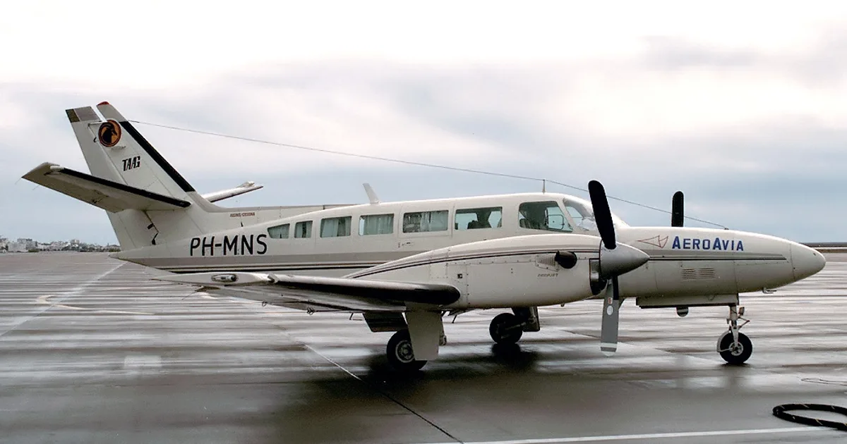
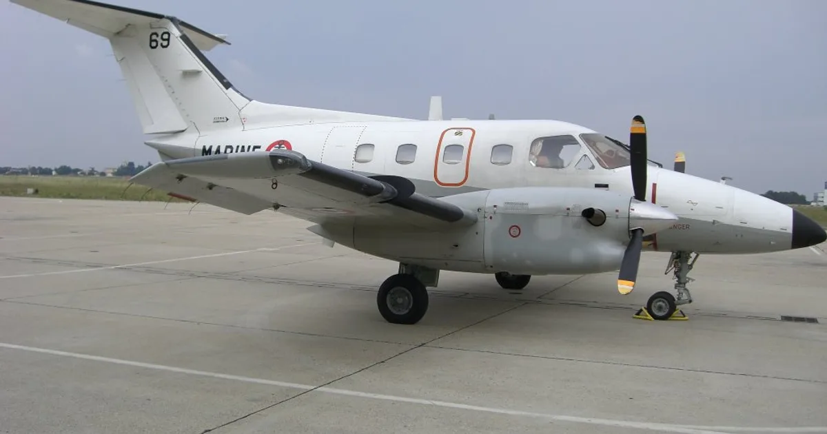
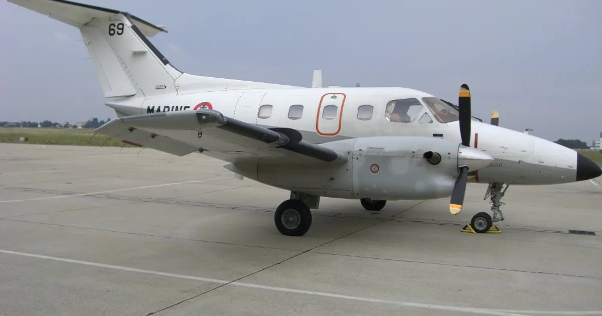
If you fly the Reims-Cessna F406 Caravan II, you may also be researching these.


In this document
General
The General section provides an overview of the Cessna 406, including specifications such as engine details, fuel capacity, and weight limitations. It outlines the aircraft's dimensions, including a maximum height of 13.93 feet and a total wing area of 252.74 square feet. The section also includes information on the engines, which are Pratt and Whitney Canada Inc. models, and the propellers used.
Performance
This section details the performance capabilities of the Cessna 406, including maximum takeoff weight of 9360 pounds and maximum cruise power at 15,000 feet yielding 216 KTAS. It also covers range and endurance, with maximum range at 20,000 feet being 1281 nautical miles.
Limitations
The Limitations section outlines critical operational limits, including airspeed limitations for various configurations, weight limits, and center-of-gravity limits. For instance, the maximum flap extended speed is 200 knots, and the maximum gear operating speed is 180 knots.
Emergency Procedures
This section provides guidelines for handling emergencies, including engine failure and other critical situations. It emphasizes the importance of recognizing engine failure at V1 and the procedures to follow to ensure safety.
Weight and Balance
This section discusses the weight and balance considerations for the Cessna 406, including maximum ramp weight of 9435 pounds and maximum zero fuel weight of 8500 pounds. It provides details on loading configurations and the implications for flight safety.
Safety notes
- Aviation gasoline is restricted to emergency use only.
- Ensure the airplane is within operating limitations as outlined in the manual.
Full document text
ZIuessnal Information Manual A Memb€r ol GAMA Cessna Aircraft Company Model406 THIS MANUAL INCORPORATES INFORMATION ISSUED THRU REVISION 2 TO THE PILOT'S OPERATING HANDBOOK AND FAA APPROVED AIBPLANE FLIGHT MANUAL DATED 1 JULY 1986. COPYRIGHT O !995 C€ssna Aircraft Company Wichita, Kansas USA Original lssue - 1 Julv 1986 Dt624-13 INTRODUCTION CONTENTS SECTION CONTENTS MODEL 406 2 LIMITATIONS....... 3 EMERGENCY PROCEDURES ... " 4 NORMAL PROCEDURES ..... 5 PERFORMANCE .. 6 WEIGHT AND BALANCE ? DESCRIPTION OF THE AIRPLANE AND ITS SYSTEMS 8 HANDLING,SERVICEANDMAINTENANCE . 1 GENERAL 9 SUPPLEMENTS .. ALPHABETICAL INDEX .. " . Index-1 2-L 3-1 4-l o-r 6-1 7-l 8-1 9-1 Contents Original lssue - 1 JulY 1986 SECTION I GENERAL TABLE OF CONTENTS Page THREE-VIEW DRAWING ..,.....7-2 INTRODUCTION ........1-3 ENGINES .......1.4 PROPELLERS .......... l-4 FUEL.. ........1-5 - oIL . ....'.....1-6=r L.raxluuM cERTIFICATED wEIGHTS .... 1-6 STANDARD AIRPLANE WEIGHTS ....,.. 1-8 CABIN, BAGGAGE AND ENTRY DIMENSIONS . . . . . . , . , . . . 1-9 SPECIFIC LOADINGS ...1-11 SYMBOLS, ABBREVIATIONS AND TERMINOLOGY ....... 1.11 General Airspeed Terminology and Symbols ....... 1-11 Meteorological Terminology .....1-13 Power Terminology .... .......1-14 Engine Controls and Instruments Terminology '.... 1-15 Airplane Performance and Flight Planning Terminology . . . . 1-16 Weight and Balance Terminology ... .....1-1? MODEL 406 SECTION 1 GENERAL Originat tssue - 1 July 1986 1-1 SECTION 1 GENERAL 1. MODEL 406 13.15'* NORMAL PROPELLER TIP TO GROUND CLEARANCE IS 0.85 TOTAL WING AREA INCLUOING NACELLES AND FUSELAGE WITHIN THE WING PLANFORM IS 252.74 SQUABE I\,IINIMUM TURNING DISTANCE IS 63.39 FEET. REFER TO FIGURE 7-t1 FOR ADOITION INFORMATION. * l\,iAxll\,lUl\,1 HEIGHT OF AIRPLANE WITH NOSE GEAR DEPRESSED IS I3.93 FEET. 12.4e'J Figure l.-1 THRED-VIEW DRAWING Original lssue NOTICE AT THE TIME OF ISSUANCE, THIS INFOR. MATION MANUAL WAS AN EXACT DUPLI. CATE OF THE OFFICIAL PILOT'S OPERAT. ING HANDBOOK AND FAA APPROVED AIRPLANE FLIGHT MANUAL AND IS TO BE USED FOR GENERAL PURPOSES ONLY. IT wILL .|GI U KEPT CURRENT AND, THEREFORE, CANNOT BE USED AS A SUBSTITUTE FOR THE OFFICIAL PILOT'S OPERATING HANDBOOK AND FAA APPROVED AIRPLANE FLIGHT MANUAL INTENDED FOR OPERATION OF THE AIR. PLANE.. CESSNA AIRCRAFT COMPANY ORIGINAL ISSUE - 1 JULY 1986 INTRODUCTION PERFORI,IANCE AND SPECIFICATIONS MODEL 406 PERFORMANCE AND SPECIFICATIONS WXIGHT: Meximum Rimo weisht . .. .. . .... 9435 Pounds Malisrum Takebff w;ishr . . 9360 Pounds Miximurn Landine weiel't . .. . . 9360 Pounds Miiimum zero friet w;rshi With zerc wing Locker Payload 8500 Pound8 SPEED At 8300 Pounds - - Manimurn Cruise Power at 15,000 Feet . .. . . .. .. 216 KTAS RANGE For 4?5 Gallons Usable At 6 7 Pounds per Galon (3183 pounds) Msximum Cruise Power - -A-10,000 Feet ......1027 Nauticall{ileg 236 KTAS At 20,000 Feet . . .. 1281 NauticalJvlihr 244 KTAS Maximum Raose Power - --If io,000 f""t ......... ... -... u87 Nauti-,lviler 180 KTAS At 20,000 Feet ..... 1652 Neulical Miles 8.54 Hours 194 KTAS . ... . 1851 Feet Per Minutr . . 996 Feet Per Minut€ . ... Above 30,000 Eeet I otal LANDING ST 1f9l . : :. : :. : . :. : .. : :. :. :. bii,. i;J;d; p".'.uS"l"'FlS rit ir. ... . ::::::,idi.s81fi"::ii*t"J"Ltw;i:i er Eneine) . . 9 2 quartg ...:..:., .., PRATT and WHITNEY CANADA INC. urbine enclnes. flat rated to 500 shaft hoBepower at 1900 propeller RPM sp"i,], r,ii ;r;i ai,t ii"idi,iii'!, ii"*iii,r", ir,.i,i-br,i i"ir, i:zb r#10515-2 Itanee dats includes allowances for start, taxi, tskeoff, (iu,u, desc€nt and 45 '.l1?.- rr; reserve at tFe particular cruisp power and altitude. Speeds shown sre ai mid-cmbe weigbt. The above oerformance fiqures are bssed on lhe indicst€d weights strndqd atomslh€ric conditions, level hard surfaie dry runways and no wind. They are cal.ulatecl values denved fmm flighi uesls conduced by'the Ce;na Aireraft Cop. -,1 urder carefiilv- dorumenled conaitiois a"d wiu vary with individual airplanes anti -numerow factors allecting flight p€dormance. 1 June 1988 INTRODUCTION This handbook consists of 9 sections and an alphabetical index as shown on the Contents page. This handbook includes the material required to be turnished to the pilot by FAR Part 23 and SFAR 41. It also c-ontgins supplemental data. supplied.b.y Ces^sna Aircraft Company. Specific information can be rapidly found by referring to the Con-tenis page tor the appropriate section. then referring to the Table Of Contents 9rl ,ths ,{irs!-pqge of the appropriate section, or by the use of the Arpnaoelrcal rnoex. IIOTE This hand.book includes the rnaterial reouired to be furnished to the pilot by the Federal Auiation Regulations and additionil inlormation prouid.ed by Cessna Aircraft Company and constiiutes the FAA Approued Airplane Flight ManuaL This handbook is not intended to be a zuide for basic flieht instruc- tion or a training rnanual and should not be used as one. lt is not a substitute. for alequate _and competent flight instruction, knowledge of current airworthiness directives, applicable federal air regulations or advisory circulars. . Assuring the airworthiness of the airplane is the responsibility of the airplane owner. Determining if the airplane is safe for nisha is the responsibility of the pilot in command. The pilot is also responsible for staying within _operating limitations as outlin;d by instrument markings, placar&. and- this Pilot's Operating Handbook and FAA Approved Air- plane Flight Manual. Section 1 of this handbook presents basic airplane data and general information which will be of value to the nilot. MODEL 406 SECTION 1 GENERAL 1-3 Original lssue SECTION 1 GENERAL MODEL 406 ENGINES Number of Engines: 2 Manufacturer: Pratt and Whitney Canada Inc. Encine Model Nu-mber: PTOA-112 Engine Type: Free T\rbine, Reverse Flow Z-Shafb. Compressor Stages and TVpes: 3 axial stages, - I centrifugal stage. -Combustion Chamber TYPe: Annular Turbine Stages and Type: 1 stage compression'
Show full textShow less
1 stage Power Horsepower: Flat rated at 500 shaft horsePower' Takeoff and Max Continuous: 500 shaft horsepower' Maximum Climb and Cruise: 500 shaft horsepower' PROPELLERS Number of Propellers: 2 PropellerManufacturer: McCauleyAccessoryDivision Propeller Model Number: 9910535-2 Number of Blades: 3 Propeller Diameter: 7.?5 Feet -\ Propelier Tlpe: Constant speed, full and,auto leathennq' reversrDle ano hYdraulicallY actuated. Propel-terBladeAngle: (At-30-Inch,StaLion) a) I eathered 6D.D uegrees b) Low Pitch 18.5 Degrees c) Full Reverse -13.5 Degrees 1-4 Original lssue MODEL 406 .AVIATION GASOLINE IS RESTRICTED TO EMERGENCY USE AND SHALL NOI: BE USED FOR MORE THAN 150 HOURS IN ONE OVERHAUL PERIOD. .A MIXTURE OF ONE PAR'T AVIATION GASOLINE AND THREE PARTS OF JET A. JET A.1, OR JP-s MAY BE USED FOR EMERGENCY PURPOSES FOR A MAXI. MUM OF 450 HOURS PER OVERHAUL PE. RIOD, .AUXILIABY BOOST PUMP MUST BE ON WHEN USING AVIATION GASOLINE. otE Fuel used. mLlst contain an anti-icinp additiue in compliance with MIL-l-27686E. Refdr to Section 8 for add.itionaL inforrnation. Total fuel capacity (U.S. gallons): 481.5 Usable tuel (U.S. gallons): 475.0 Orioinal lssue sEcTtoN 1 GENERAL * Aviation gasoline (all grades) is approved for emergency use only. Refer to Section z foi limidation - reouirements anif Se;tion 8 for fuel servicing information. A record oT total aviation gasoline used must be recorded in Airplane Engine Maintenance Record. NATO equivalents of the above fuels may be used. FUEL FUEL GRADE (2} FUEL SPECIFICATIONS MINIIiIUM FUEL TEI''PERATURE FOR TAKEOFF . 'c (1) SPECtFtC WEIGHT . POUNDS PER U.S. GALLON AT 60.F COLOR JET A JET A-1 JET 8 JP,1 JP.4 JP-5 JP-8 *AVrATroN (3) GASOLINE {ALL GRADES) ASTM-01655 ASTM.D1655 ASTTV-Dt655 MtL-L-56t6 MIL-T-5624 MtL-T-5624 MtL-T-831334 MIL-G-5572 AND ASTM.D91O -54 -54 -54 -54 6.7 6.7 6.8 6.7 6.0 COLORLESS COLORLESS COLORLESS COLORLESS COLORLESS COLORLESS COLORLESS 80/87 RED, lOO GREEN, lOOLL BLUE t-c sEcTtoN 1 GENERAL MODEL 406 otL Refer to Section 8 for list of approved oils and specifrcations. Total Oil Capacity (Per Engine): 9.2 U.S. Quarhs Drain and Refill Quantity (Fer Engine): Approximately 8.4 U.S' Qua*s including oil filter' Oil Quantity O*"iiitr" Iianee: Fill Lo within 2 quarts of MAX HOT or MAX - COLD (as approprilte) on dipstick' Quart markings indicate U.S. buart's low if oif is hot. For example, a dipstick reading of 3 indicates the system ,is within 2 ou-att" of MAX if oil is cold and within 3 quarts of MAX it ttre oil is hot. NOTE To obtain an accurate oil leuel reading, lt is recommended. the oil leuel be cheched' uithin 10 minutes after engine shutdown while the oil is hot (MAX HOT marhing) or prior to the firs-t- ttisht of th.e duv while - the 6iI is cold (MAX 'C1LD mdrkinil: II rnore than 10 minutes has ela.psed. since engine shutdown, and engine is stiil uarm, perforrn an engine dry motoring run before checking oil leueL. MAXIMUM CERTIFICATED WEIGHTS Maximum Ramp Weight: 9435 Pounds Maximum Takeoff Weight: 9360 Pounds Maximum Landing Weight 9360 Pounds Maximum Zero Fuel Weisht With Zero Wing Locker Payload: 8500 Pounds Maximum Weights a. Left and Right Wing Lockers - 200 pounds in Basgase each. Co-o"u?i""nt" b. Avionics Bav - 250 pounds less installed (Staridard and optional equipment. RBfer to the loading. b"iionit t"r"rior piacard in ih6 airplane avionics baggage bay. Pii"enee. c. Nose Bay - 350 pbunds less installed optional Configrirations): equipment. Refer to the loading placard in the - airPlane nose baggage baY' 1-6 1 June 1988 MODEL 406 SECTION 1 GENERAL d. Aft Cabin (Bay A) Refer to Figure 1-3 - 400 pounds (200 pounds per side). Maximum floor loading is 75 pounds per square foot. e. Aft Cabin (Bav B) Refer to Figure 1-3 - 100 pounds (50 pounds per side). Maximurn floor loading is 75 pounds per squzue foot. Maximum Weights a. Left and Right Wing Lockers - 200 pounds in Baggage each. Compartments b. Avionics Bay - 250 pounds less installed op- (Cargo Interior tional equipment. Refer to the loading placard Configuration): in the airplane avionics baggage bay. c. Nose Bay - 350 pounds less insta.lled optional equipment. Refer to the loading placard in the airplane nose baggage bay. d. Maximum carso load in anv 24-inch leneth of cabin floor is -600 pounds per bay in th! five cargo bays (Cargo A,B,C,D, & E). If the cargo has a smooth, reasonable flat lower surface, load densities of up to 200 pounds per square foot may be loaded in the cargo bays. Use pallets or beams to distribute the loads over all seat rails if adjacent cargo bays are loaded at a rate of over 75 pounds per square foot. e. Aft Cabin (Bay A) - 400 pounds (200 pounds per side). Marimun floor loading is 75 pounds per square foot. f. Aft C:abin (Bay B) - 100 pounds (50 pounds per side). Maxirnum floor loading is 75 pounds Der souare foot. g. ilefer- to Section ?, Cargo loading, for add! tional information. STANDARD AIRPLANE WEIGHTS Standard Empty Weight: (Standard interior) Basic Empty Weight: (Ootional interior with 8 seat configuration and standard avionics) Basic Empty Weight: (Optional interior with 9 seat configuration and standard avionics) Basic Empty Weight: (Optional interior with 10 seat configuration and standard avionics) Original lssue 5033 Pounds 5136 Pounds 5160 Pounds 5185 Pounds 'l-7 SECTION 1 GENERAL MODEL 406 Basic Emptv Weisht: 5050 Pounds rOotional-interior with 11 seat configuration and standard avionics) Basic Emptv Weight: 5067 Pounds (28 inch spacing) (Ontional-interior with 12 seat 5061 Pounds (31 inch spacing) co;figuration and standard avionics) Basic Empty Weight: 5092 Pounds (Ootional interior with 14 seat ioifiguration and standard avionics) Basic Empty Weight: 4892 Pounds (Cargo interior) Maximum Useful Load: 4402 Pounds (Standard interior)* Maximum Useful Load: 4299 Pounds (Ontional interior with 8 seat coifiguration and stsndard avionics)* Maximum Usefirl Load: 4275 Pounds (Ortional interior with 9 seat ioifiguration and standard avionics)* Maximum Useful Load: 4250 Pounds (Optional intBrior with 10 seat confrzuration and standard avionics)* Maximum Useful Load: 4385 Pounds (Optional interior with 11 seat confi guration and standard avionics)* Maximum Useful Load: 4368 Pounds (28 inch spacing) (Ontional interior with 12 seat 43?4 Pounds (31 inch spacing) configuration and standard avionics)* Maximum Useful Load: 4343 Pounds (Optional interior with 14 seat ioirfi4rration and standard avionics)* Maximum Useful Load: 4543 Pounds (Cargo interior)* *Based On Maximum RamP Weight. 1-8 Original lssue MODEL 406 AND DOOR NOSE AAGGAGE PASSENGEB INTEBIOR PASSENGER INTERIOR SECTION 1 GENERAL BAY BAY AB r*r_r 43.4 40.0" 60852002 60851002 60866036 1-9 :ll' ,_r -l r-'-i !l*o pi'" ,;n 49.0" VIONICS AAY NOSE AAGGAGE WHEEL WELL VIONICS BAY AND DOOR 224.9" PASSENGER INTERIOR . Ifgufe l-2 (Sheet 1 of 2) CABIN. BAGGAGE AND ENTRY DIMENSIONS 1 June 1987 sEcTroN 1 GENERAL MODEL 406 CABGO INTERIOR r60.72"- --------rf*='=FrrI 28.3'l I ll ) L__l_L_==g, BAGGAGE AND CARGO COMPARTMENT VOLUME . CUBIC FEET AVIONICS BAY NOSE wrNG LOCKER EACH (STD) AFT CABIN (BAY A AND B) cABrN (CARGO A,B,C,D AND E) 11.0 15.0 10.55 31.7 201.0 608520o2 608s10q2 6085100r Figure l-2 (Sheet 2 of 2) CABIN. BAGG:AGE AND ENTRY DIMENSIONS 50.6"(47.7' AT FLOOR) BAY BAY 56.0" (51.4"AT FLOOR) (AT FLOOR) AND DOOR 1 -10 Original lssue MODEL 406 SPECIFIC LOADINGS Wing Loading: Power Loading: IAS 37.03 pounds per square foot. 9.36 pounds per horsepower. Calibrated Airspeed means indicated speed of an air- plane corrected for position and instrument error. Calibrated airspeed is equal to true airspeed in stan- dard atmosphere at sea level. Acceleration due to gravity. Ground Speed is the speed of an airplane relative to the ground. Indicated Airspeed is the speed of an airplane as shown in the airsDeed indicator when corrected for instrument error. iAS values published in this Hand- book assume zero instrument error. Calibrated Airspeed expressed in knots. Indicated Airspeed expressed in knots. True Airspeed expressed in knots. Mach Number is the ratio of true airspeed to the speed of sound. Distance expressed in Nautical Miles. True Airsneed is the airsneed of an aimlane relative to uadisfiirbed air which' is the CAS corrected for altitude, temperatue and compressibility. Takeoff Decision Speed is the speed at which an engine failure or other cause is recognized, the dis- tance to continue the takeoff to 50 feet or bring the airplane to a stop will not exceed the scheduled field length distance. The first action required to stop or continued is assumed to have been initiated by Vr. Takeoff Safety Speed is the speed at 50 feet above the runway surface as demonstrated in flight during takeoff with one enghe inoperative. SECTION 1 GENERAL SYMBOLS, ABBREVIATIONS AND TERMINOLOGY GENERAL AIRSPEED TERMINOLOGY AND SYMBOLS CAS G GS KCAS KIAS KTAS M NM TAS Original lssue 1-11 Vrn V"" SECTION 1 GENERAL V"" VLo V"co V,ro/M"o MODEL 406 Maneuvering Speed is the maximum speed at which application of full available aerodynamic control will not overctress the airplane. Critical Ensine Failure Speed is the speed at which the ensine was failed during certification flight test- ins to ?etermine accelerateil stop and accelerated go distances. Maximum Flap Extended Speed is the highest speed permissible with wing flaps in a prescribed extended position. Maximum Landins Gear Extended Speed is the maximum speed aiwhich an airplane can be safely flown with the landing gear extended. Maximum Landins Gear Operating Speed is the maximum speed ai which the landing gear can be safely exteniied or retracted. Air Minirnurr Control Speed is the rninirnum flight speed at which the airplane is directionally and lat- eiallv controllable as determined in accordance with Fedeial Aviation Regulations. Airplane certfication conditions include one engine becoming- inoperative and feathered; not more than a 5-degree bank toward the ooerative encine; takeoff power on operative en- gine: ianding geir up; flaps in ta.keoff position; and most cntlcal cent€r-ol-gTavl[y. Maximum Operatins Limit Speed is the speed limit that may n;t be aeliberat€ly exceeded in normal flight oplrations. V is expresied in knots and M in Mach Number. Rotation Speed is the speed at which rotation is initiated duiine taleoff to attain the V, clinb speed at or before a Leight of 50 feet above runway surface has been reached. Stalline Speed or the minimum steady flight speed at which Ihe-aimlane is controllable. Stalline Speed or the minimum steady flight speed at which -th6 airplane is controllable in the landing confizuration. vR vs Vso 1-12 Original lssue MODEL 406 VssB vx Vts" V"s. - ISA OAT SECT'ON 1 GENERAL Intentional One Engine Inoperative Speed is a mini- mum soeed. selected bv the manufacturer, for inten- Lionally rendering one engine inoperative, in flight, for pilot training. Best Anele-of-Climb Speed is the airspeed which delivers ihe greatest gain of altitude in the short€st possible horizontal distance. One Encine Inoperative Best Angle-of-Climb Speed is the a-irspeed which delivers the $eatest gain of altitude in the shortest possible horizontal distance Best Rate-of-Climb Speed is the airspeed which de- livers the greatest gain in altitude in the shortesi possible time. One Ensine Inoperative Best Rate-of-Climb Speed is the airspeed which delivers the greatest gain in al- titude in the shortest possible time. METEOROLOGICAL TERMINOLOGY 'c "F Indicated Pressure Altitude IOAT Temperature expressed in degrees Celsius. Temperature expressed in degrees Faluenheit' The number actuallv read from an altimeter when the barometric subsiale has been set to 29.92 inches of mercury (1013.2 millibars). Indicated OuLside Air Temperature is the tempera- ture indicated on the pilot's outside air temperature indicator. The indication is not adjusted for instru- ment error or temperature compressibility effects. Int€rnational Standard Atmosphere in which: (1) The air is a dry perfect gas; (2) The temperature at sea level is 15 degrees Celsius; (3) The pressure at sea level is 29.92 inches Hg. ( 1013-.2 millibars); (4) The rcmoerature sradient from sea level to the ' altitude irt ,rhich-the temperature is -56.6 de- grees Celsius. is -1.98 degrees Celsius per 1000 Ieei. Outside Air Temperature is the free air static t€m- Derature, obtained either from inflight t€mperature indications or ground meteorological sources adjusted for instrumentirror and compressibility effects. Original lssue 1-13 SECTION 1 GENERAL Pressure Altitude MODEL 406 Altitude neasured from staldard sea-level pressure (29.92 inches Hg.) by a pressure or barometric altim- eter. It is the indicated pressure altitude corrected for position and instrument error. In this handbook, altimeter instrument erroni are assumed to be zero. Actual atmospheric pressure at freld elevation. An error in the indication of temperature caused by airflow over the temperature probe. The error varies, depending on altitude and abspeed. The wind velocities recorded as variables on the charts of this handbook are to be understood as the headvind or tailwind components of the reported wrn0s. Station Pressure Temperature Compressibility Effects Wind POWER TERMINOLOGY Auto Feather Critical Altitude Cruising Climb Power ITT Flameout Flat Rated Flight Idle Power Gas Generator RPM (Ns) Ground Idle Power A systen designed to automatically reduce drag of an inoperative engine by moving the propeller to feath- er. The maximum altitude at which in standard tem- perature it is possible to maintain a specified power. The power recommended to operate the airplane in a cmise climb (a continuous gradual clinb) profile. Interturbine Temperature. Unintentional loss of combustion chamber flame dur- ing operation. Constant horsepower over a specific altitude range. The power required to run an engine, in flight, at the lowest speed that will ensure satisfactory engine op- eration and airplane handling characteristics. Indicates the percent of gas generator rpm based on a figure of 100 percent at 37,500 rpm. The power required to run an engine on the ground, as slowly as possible, yet sufficient to ensure satisfac- tory engine, engine accessory, and airplane operation with a minimum of thrust. 1-14 Original lssue MODEL 406 Hot Start Maximum Continuous Power Maximum Cruise Power Power T\rrbine RPM (Nf) ^ Propeller RPM (Ne). RPM Reverse Thrust SHP Takeoff Power Torque Windmill Beta Mode Fuel Control Lever Gas Generator Governor ITT Gage ENGINE CONTROLS AND INSTRUMENTS TERMINOLOGY .EETL"$I An engine start, or attempted start, which results in ITT exceeding 1090 degrees Celsius. The oower developed at the maximum continuous torqui limit, ITT jimit: or Ng limit. This is equiv- alent to takeoff power. The power developed at the maximurn cruise torque limit, ITT limit or Ng limit. Indicates the percent of power turbine speed based on a figure of 100 percent at 33,000 rpm and a propeller speed (No) of 1900 rpm. Indicates propeller speed in rpm. Revolutions Per Minute. The thrust produced when the propeller blades are rotated past flat pitch into the Beta iange. Shaft horsepower means the power delivered at the propeller shaft. The maximum power permissible for takeoff. A measurement that is proportional to the power output of the engine. Propeller rotation from airstream inputs. Ensine operational mode in which propeller blade pitih is cbntrolled by the cockpit power lever. May be used during ground operations only. Cockpit Control lever which sets the fuel control in eithei "RUN" or "CUTOFF". Regulates the gas generator to the speed selected by the cockpit power lever. Interturbine temperature gage displaying air tem- perature between the cornpressor turbine and power turbine. Original lssue 1-15 MODEL 406 Flyweight operated fuel met€ring device, housed in the propeller governor. lt prevents engine overspeed in the event of a malfunction of the propeller gov- ernor. Regulates the RPM of the propeller by increasing or decreasing the propeller pitch through a pitch change mechanism in the propeller hub. Power Control Cockpit lever used to set gas generator Bpeed. During Lever Beta node the power lever controls propeller blade angle and speed. Propeller Lever Cockpit lever used to set propeller RPM. A gearbor mounted governor which dumps propeller oil pressure to prevent engine danage should the propeller governor fail. Indicates the speed of the gas generator (Ng) or propeller (Np). Torque Meter The instrument that indicates the torque output of tt)e englne gear Dox. AIRPLANE PERFORMANCE AND FLIGHT PLANNING TERMINOLOGY Accelerate-Go The distance required to accelerate an airplane to Vt Distance and assuming pilot recognizes an engine failure at Vt, continues takeoff on the remaining engine to a height of 50 feet. Accelerate-Stop The distance required to accelerate an airplane to V1 Distance and assuming pilot recognizes an engine failure at Vr, brings the airplane to a stop. SECTION 1 GENEBAL Overspeed Governor Propeller Governor Fropeller Overspeed Governor Tachometer Aerobatic Maneuver An intentional maneuver involving an abrupt change of an airplane's attitude, an abnornal attitude, or abnormal acceleration, not necessary for normal flieht. Balked Landing A balked landing is. an aborted landing.(i.e., all en- gines go-around in the landing configuration). Balked Landing The minimum speed at which a transition to a Transition balked landing climb should be attempted (from Speed 5O-foot obstacle height). 1-1 6 Original lssue Climb Gradient The demonstrated ratio of the change in height dur- ing a portion of a climb to the horizontal distance traversed in the same time interval. Demonstrated The demonstrated crosswind velocity is the velocity Crosswind of the crosswind component for which adequate con- Velocity trol of the airplane iiuring takeoff and landing was actually demonstrated during certification tests. The value ihown is not considered to be limiting. This value is not an aerodynamic limit for the airplane. Maneuverins Maneuvering fuel is the usable fuel as shown in Fuel - Section 2 foi all airplane confrgurations, provided the roaximum side slip duration is not exceeded. MODEL 406 Maximum Effective Braking Arm Basic Empty Weight C.G. Arm C.G. Limits Jack Point MAC SECTION 1 GENERAL The horizontal distance from the reference datum to the center-of-gravlty (C.G.) of an item. Standard empty weight plus installed optional equip- menf,. The maximum anount of braking pressure that can be applied to the toe brakes without locking the wheels. MEA Minimum enroute IFR altitude. Route Secment A part of a route' Each end of that part is identified - bvi (1) a geographical location; or (2) a point at wiich a d"frniie ridio frr can be established' WEIGHT AND BALANCE TERMINOLOGY Center-of-Grav- The point at which an airplane would balance if itv suspended. Its distance from the reference daturr is - fouird by dividing the total moment by the total weight of the airPlane The arm obtained by adding the airplane's individual moments and dividGg the sum by the total weight. The ertreme center-of-sravitv locations within which the airplane must be oplratcil at a given weight. One of the three points on the airplane designed to rest on a jack. The Mean Aerodvnamic Chord of a wing is the chord of an imaginary airfoil which throughout the flight range will f,ave the same force vectors as those of the wing. Original lssue 1-17 SECTION 1 GENERAL Maximum Landing Weight Maximum Ramp Weight Maximum Takeoff Weight Maximum Zero Fuel Weight Moment Payload Reference Datum Residual Fuel Standard Empty Weight Station Tare Unusable Fuel Usable Fuel Useful Load MODEL 406 Maximum weight approved for the landing touch- oown. Maximum weieht aDDroved for sround maneuver. (It includes weighl of siirt, taxi anil run-up fuel.) Maximum weight approved for the start of the takeoff run. Maximum weight exclusive of usable fuel. The product of the weight of an item multiplied by its arm. (Moment divided by a constant is used to simplifu balance calculations by reducing the number of digits.) Weight of occupants, cargo and baggage. An imaeinarv vertical nlane from which a.ll horizon- tal distinces-are measuied for balance purposes. The undrainable fuel remaining when the airplane is defueled in a specfic attitude by the normal means and procedures specified for draining the tanks. Weight of a standard airplane including unusable fuel, full operating fluide and full oil. A location along the airplane fuselage given in termg of distance from the reference datum. Tare is the weight of the chocks, blocks, stands, etc. used when weighing an airplane, and is included in the scale readings. Tare is deducted from the scale reading to obtai; the actual (net) airplane weight. Fuel remainins after fuel runout tests have been completed in iccordance with governmental regula- tions. Fuel available for flight planning. Difference between ramp weight and the basic empty weight. 1-18 Original lssue MODEL 406 SECTION 2 LIMITATIONS sEcTloN 2 LIMITATIONS TABLE OF CONTENTS AIRSPEED LIMITATIONS AIRSPEED INDICATOR MARKINGS POWERPLANT LIMITATIONS POWERPLANT INSTRUMENT MARKINGS MISCELLANEOUS INSTRUMENT MARKINGS WEIGHT LIMITS . CENTER-OF-GRAVITY LIMITS MANEUVER LIMITS . FLIGHT LOAD FACTOR LIMITS FLIGHT CREW LIMITS KINDS OF OPERATIONAL EQUIPMENT LIMITS ' FUEL LIMITATIONS . . MAXIMUM OPERATING ALTITUDE LIMIT . OUTSIDE AIR TEMPERATURE LIMITS MAXIMUM PASSENGER SEATING LIMITS . PLACARDS INTRODUCTION 2-6 2-6 Page 2-4 2- 10 2-tl 2-77 2-73 2-t3 2-13 2-13 2-76 2-16 2-76 2-r7 2-18 2-1 (2-2 btank) SFAF 41 Original lssue - 1 JulY 1986 MODEL 406 SECTION 2 LIMITATIONS INTRODUCTION Section 2 presents the operating limitations, the significance of such limitations, instrument markings, iolor coding and basic placards neces- sarv for the safe operation oi ihe airplane,- its powerplants' standard svsiems and standaid equipment. The li.rnitations included in this sec- tion and Section 9 are aiprbved by the Federal Aviation Administration. Observance of these opeiating limitations is required by Federal Aviation Regulations. Oneration in countries other than the United States may require observance of other limitations, procedures or performance data in ap- plicable supplements. NOTE oRefer to Sectinn I for arnended linitations for airplanes equipped with specific optianal sys' terns. OThe airspeed.s listed in the Airspeed, Limita- tions chari (Figure 2-1) and Airspeed Indicator Marhings charl (Fieurb 28) are'based on Air- speed, Calibration d'ata shoun in Section 5. 2-3 Original lssue AIRSPEED LIMITATIONS Airspeed limitations and their operational significance are shown in Figure 2-1. SECTION 2 LIMITATIONS 2-4 MODEL 406 cAs tAs REMARKS MANEUVEFING SPEED 9360 POUNDS AT SEA LEVEL IREFER TO FIGURE 2'2) v; {KNoTS) 163 162 DO NOT MAKE ABRUPT CONTROL MOVEMENTS ABOVE THIS SPEED. MAXII\,!UM FLAP EXTENDED SPEED T.O, AND APPR POSITIONS LAND POSITIONS VFE (KNOTS) 200 r80 200 180 DO NOT EXCEED THIS SPEED WITH THE GIVEN FLAP SETTING. MAXIMUM GEAR OPERATING Vse (KNOTS) 180 180 OO NOT EXIENO OR RETRACT LANDING GEAR ABOVE THIS SPEED. MAXIi/tUM GEAR EXTENDED VLE (KNOTS) 180 180 DO NOT EXCEED THIS SPEED WITH LANDING GEAR EXTENDED. AIR I\.4INI[4UM CONTROL SPEED WITH WING FLAPS - T.O. Vucr(KNOTS) NOTE Buffet can be encountered os hieh as 95 KIAS uith airplane at matimum taieofl weight and the wing flaps in the UP Do$ition. FLaps UP 'taheof[ is noi approved. 91 90 THIS IS THE MINII\4UM FLIGHT SPEED AT WHICH THE AIRPLANE IS CONTROLLABLE WITH ONE ENGINE INOPERATIVE AND A 5 DEGREES BANK TOWARDS THE OPERATIVE ENGINE. MAXIMUM OPERATING LIMIT SPEED VMO {KNOTS) rlrMo (MACH NUMBER) 230 0.52 229 0.52 DO NOT EXCEEO THIS SPEED OR MACH NUMBER IN ANY OPERATION. AS INDICATED BY BABEER POLE IRED AND WHITE NEEDLE). ON AIRSPEED INDICATOR, Figure 2-1 AIRSPEED LIMITATIONS Original lssue MODEL 406 CON0lTl0NSl 1. Landino qear - UP 2. Wing l6pis - UP 120 EXAMPLE: Weioht - 9000 Pounds Altitlde - 10.000 Feet SECTION 2 LlirtlTATIONS P rs ru o f tF 't0 140 160 SPEED (VA) - KIAS 180 Maximum Maneuvering Spe€d - 162 KIAS Ficure 2-2 MAXIMUM MANEUVERING SPEEDS Original lssue z-a WEIGHT - POUNOS sEcTloN 2 LIMITATIONS MODEL 406 AIRSPEED INDICATOR MARKINGS Airspeed indicator marking and their color significance are shown in Figure 2-3. POWERPLANT LIMITATIONS Number of Engines: 2 Engine Manufacturer: Pratt and Whitney Canada Inc. Engine Model Number: PT6A-112 Engine Operating Limits: Refer to Figure 2-4. Starting Cycle Limitations: a, External Power Or Battery Start - 30 seconds On 60 seconds Off, - 30 seconds On 60 seconds Ofi - 30 seconds On 30 minutes Off. Repeat the above cvcle as required. Minimum Engine Torque For Takeoffi Refer to Fizure 5-10 for minimum value for which takeoff oerformance can be obtained. 1-O MARKING IAS VALUE' OR RANGE SIGNIFICANCE RED RADIAL 90 KNOTS AIR MINIMUM CONTROL SPEED WITH WING FLAPS IN THE T.O. POS|T|ON. WHITE ARC WIDE NARROW 75 TO 180 75 TO 94.5 94.5 TO 180 OPEBATING SPEED RANGE WITH WING FLAPS IN LAND POSITION. LOWEB LIMIT IS MAXIMUI\,i WEIGHT STALLING SPEED IN LANDING CONFIGURATION. UPPEF LII/IT IS MAXIMUM SPEED PERMISSIBLE WTH FLAPS IN LAND POStTtON. THE TRANSITION POINT FFOM WIDE TO NARROW ARC IS THE STALL SPEED WITH WING FLAPS IN UP POSITION. BLUE ARC 104 TO 108 KNOTS OPERATING SPEED RANGE WITH ONE ENGINE INOPERATIVE EEST RATE.OF.CLIMB SPEED, STANDARD DAY CONDITIONS AND MAXIMUM GROSS WEIGHT. LOWER LIMIT IS SPEED AT 15,OOO FEET, UPPER LIMIT IS SPEED AT SEA LEVEL, RED AND WHITE BARBER POLE 229 KNOTS 0.52 MACH MAXIMUM OPERATING SPEED. BARBER POLE INOICATES 229 KIAS UNTIL REACHING APPROXIMATELY 22,OOO FEET. ABOVE THIS ALTITUDE, IT WILL INDICATE CONSTANT 0,52 MACH. Figure 2-3. AIRSPEED INDICATOR MARKINGS Original lssue MODEL 406 SECTION 2 LIMITATIONS (l I Maximum permissible sustained torque is 1477 foot-pounde. Ne must be set so as not to exceed engine operating limitations. Refer to PLAC- ARDS this section for maximum torque table. (2) For every 10 degrees Celsius (18 degrees Fahrenheit) below -30 degrees Celsius (-22 degrees Fahrenheit) ambient lempemture, reduce maxbnum allowable N" by ).2 percent. (3) Normal oil pressure is 80 to 100 PSIG at gas generator speeds above 27,000 RPM (72 percent) with oil temperature between 60 to 70 degrees Celsius (140 to 158 degrees Fahrenheit). Oil pressures below 80 PSIG are un- desirable and should be tolerated only for ihe completion of the flight, preferably at reduced power setting. Oil pressures below normal should be ieporred as an engine riiscrepancy a-nd shoutd be conected before next flight. Oil pressures below 40 PSIG are unsafe and require that either the etrgine be ihut down or a landing be made as soon as pbssible using the minimum power required to sustain flight. (4) If maximum torque is used, \ must be set so aB not to exceed engine operating limitations. (5) Reverse powe! ooeration is limit€d to one minute. 1 c, Th""" uutues are time limited to two seconds. (?) For increased oil service life, an oil temperature between 74 to 80 degrees Celsius (165 to 176 degrees Fahrenheit) is recommended. A minimum oil temperature of 55 degrees Celsius (130 degrees Fahrenheit) is recommended for fuel heater operation at takeoff power. (8) Maximum cluige power limits vary with altitude and temperature. For ' maximum cruise power limits lefer 6 MAXIMUM CRUISE POWER trbleo in Section 5. l{OtE 100 percent Ns (2) is 37,500 RPM Figur€ 2-4 ENGINE OPERATING LIMITS 2-7 POWEN SETTING ENGINE OPESATING LIMITS iraxtmuM GAS GENERATOR RPM irf PROPELLER RPM Np otL PRESSURE PSIG (3) olL TEMPERATURE (7) FT.LBS 0) ITT'C TAKEOFF AND MAXIMUM CONTINUOUS 1382 725 101.6 1900 80 to 100 10 to 99 MAXIMUM CLIMB/ cRUrsE (8) 1382 't477\4) 695 '| 01.6 1900 1 600 {4) 80 to 100 10 to 99 685 40 MtN. 40 to 99 (s) 1382 725 101.6 1815 80 to 100 0t099 ACCELERATTON (6) 1900 825 102.6 2090 0to99 STARTING 1090 (6) 40 Mlr,l. Original lssue * Aviation easoline (all srades) is approved for emergency use only. A record of total aviation gaioline used must be recorded in the Airplane Engine Maintenance Record. (l) Minimum sLarting t€mperature is thal given or the mini-- mum allowable oil temperature. -40 degrees Celsius (-40 degrees Fahrenheit) whichever is warmer. (2) Refer to Section 8 for fuel servicing information. SECTION 2 LIMITATIONS 2-8 MODEL 406 .AVIATION GASOLINE IS RESTRICI| ED TO EMERGENCY USE AND SHALL NOT BE USED FOR MORE THAN 150 HOURS IN ONE OVERHAUL PERIOD. .A MIXTURE OF ONE PART AVIATION GASOLINE AND THREE PARTS OF JET A, JET A-1. JP-1. or JP-\ MAY BE USED FOR EMERGENCY PUiPOSES FON A MAXI- MUM OF 450 HOURS PER OVERHAUL PE- RIOD. .AUXILIARY BOOST PUMP MUST BE ON WHEN USING AVIATION GASOLINE. (3) When using aviation gasoline the maximum fuel and am-' bient tempirature foi takeoff is 32 degrees Celsius (90 degrees Fahrenheit). a. NATO equivalents of the above fuels may be used. b. Fuel used must contain anti-icing fuel additive in compliance with MIL-I-276868. Fuel Specification and Approved Fuel Additives: GRADE (2) FUEL SPECIFICATIONS MINIMUM FUEL TEMPERATURE FOR TAKEOFF . 'c (1) SPECtFtC WEIGHT - POUNDS PER U.S. GALLON AT 600F COLOR JET A JET A.1 JET B JP.1 JP.4 Jt,-5 JP-8 *AVrATroN (3) GASOLINE (ALL GRADES) ASTM.D1655 ASTM-D1655 ASTM.D1655 MtL-L-56t6 l?t lL-T-5624 MtL-T-5624 M tL-T-831 33A MI1.G.5572 AND ASTM.D91O -31 -31 -54 -54 -54 -31 -31 -54 6.5 6.8 6.7 6.0 COLORLESS COLORLESS COLORLESS COLORLESS COLOBLESS COLORLESS COLORLESS 80/87 RED, 1OO GREEN, l OOLL BLUE Original lssue MODEL 406 Fuel Additive: The fuel used compliance with during refueling. SECTION 2 LIMITATIONS in the aimlane must have an anti-icine additive in MIL-I-2?6'86E, incorporated or added into the fuel JP.4 AND JP-, FUELS PER M1L.7,5624 AND JP,8 FUEL PER MIL-T-831334 CON- I:AIN THE CORRECT PREMIXED qUANTI- TY OF AN APPROVED TYPE OF ANTI- ICING FUEL ADDITIVE AND NO ADDI- TIONAL ANTI-ICE COMPOUNDS SHOULD BE ADDED. Ethylene glycol monomethyl ether (EGME) compound in compliance with MIL-I-27686E. if added. must be carefullv mired with the fuel in the tank in concentrations not to exceed 0.ls'percent by volume. The minimum EGME concentration within the fuel tank is 0.035 percent bv volume.The minimum EGME concentration for fuel beine added to th-e fuel tank is 0.060 percent by volume. REFER TO SECTION 8 FOR PROPER HANDLING AND SEBVICING OF EGME. MIXING OF THE EGME COMPOUND WITH THE FUEL IS EXTREMELY IMPONTANT BECAUSE CONCENTRATION /N 'XC'SS . OF THAT BECOMMENDED (0.15 PERCENT BY VOLUME MAXIMUM) WILL RESULT IN DETRIMENTAL EFFECTS TO THE FUEL I:ANKS, SUCTI AS DETERIORATION OF PROTECTIVE PRIMER AND SEALANTS AND DAMAGE TO O-RINGS AND SEA'S IN THE FUEL SYSTEM AND ENGINE COMPO. NEN?S. USE ONLY BLENDING EqUIP- MENT THAT IS RECOMMENDED BY THE MANUFAC'| UREN TO OBTAIN PROPER PROPORTIONING. z-Y Original lssue SECTION 2 LIMITATIONS MODEL 406 Preflight Checks: a. The overspeed governor check shall be performed: before the fusi flisht of the dav, if there is an indication of malfunction, after erigine control syst€m maintenance, or if adjustment has been made. b. Autofeather shall be checked before each flight and must be operative for takeoff. Oil Specification: a. Refer to Section 8 for list of approved oils and specifications. b. When addine oil, service the engines with the type and brand which is currently being used in the engines. Do not mir tJpes or brands of oils. c. Tvpe II oils in compliance with Pratt and Whitney Canada Inc, Soicification PWA 521. d. Oi conforming to Pratt and Whitney Canada- Inc., Service Bulletin Numb.-er 12001 and all revisions or supplements there- to, must be used. Propellers: a. Number of Propellers: 2 b. Manufacturer: McCauley Accessory Division of Cessna Aircraft Company. Cessna Part Number: 9910535-2 Number of Blades: 3 Diameter: 7.?5 Feet Maximum Operating Speed: 1900 RPM Blade Angle: (At 30-Inch Station) (1) Feathered 85.5 degrees (2) Low Pitch 18.5 degrees (3) Full Reverse -13.5 degrees h Flight operation with power levers retarded below FLIGHT IDLE are prohibited. POWERPLANT INSTRUMENT MARKINGS Torque Indicators: a. 1382 Foot-Pounds Maximum Takeoff And Climb Torque At 1900 RPM (Yellow Radial) b. 0 to 1477 Foot-Pounds (Green Arc) c. 14?? Foot-Pounds Maximum Cruise Torque At 1600 RPM (Red Radial) ITT Indicators: 725 degrees Celsius (Red Line) 0 degrees to 695 degrees Celsius (Green Arc) 695 degrees to 1090 degrees Celsius (Yellow Arc) 1090 degrees Celsius (Red Triangle) Original lssue d. f. a. b. c. d. 2-'10 MODEL 406 SECTION 2 LIMITATIONS Gas Generator RPM Indicators: a. 101.6 percent RPM (Red Line) b. 52 percent to 101.6 percent RPM (Green Arc) Propeller RPM Indicators: a. 1900 RPl"{ (Red Line) b. 1600 to 1900 RPM (Green Arc) Oil Pressure Indicators: a. 40 and 100 PSI (Red Radial) b. 40 to 80 PSI (Yellow Arc) c. 80 to 100 PSI (Green Arc) Oil Temperature Indicators: a. -40 degrees and *99 degrees Celsius (Red Radial) b. *10 degrees to i-99 degrees Celsius (Green Arc) c. -40 degrees to + 10 degrees Celsius (Yellow Arc) MISCELLANEOUS INSTRUMENT MARKINGS Instrument Air: a. Red Line: 2.25 PSI b. Green Lrc: 2.25 to 2.75 PSI Oxygen Pressure: a. Yellow Arc: 0 to 300 PSI b. Green Arc: 1550 to 1850 PSI c. Red Line: 2000 PSI Propeller Deice Ammeter; a. Individual indicators will be marked LEFT or RIGHT. b. White arc operating range will be marked with the high end of the scale marked with HI. c. A normal operating green arc will be provided between the HI and LOW ends of the white arc operating range. ^ wErcHT LrMlrs Maximum Ramp Weight: 9435 Pounds Maximum Takeoff Weight: The takeoff weight is limited by the most restrictive of the follow- | ing requirements: a. Maximum Takeoff Weight: 9360 Pounds. b. Maximum takeoff weight to achieve takeoff climb requirements from Figure 5- 11. c. Maximum takeoff weight as permitted by field length from Fizure 5-12. 2-11 1 June 1987 d. Maximum takeoff weight as permitted by the demonstrated brake energy limits from Figure 5-13. Maximum Landing Weight: The landing weight is limited by the most restrictive of the follow- ing requirements: a. Maximum Landing Weight: 9360 Pounds. b. Landing field length required from Figure 5-35. lMarimum Zcro Fuel Weight with Zero Wing I Locker Payload: 8500 Pounds Maximurn Weights In Baggage Compartments: (Standard and Optional Passenger Interior Confrgurations) Left and Right Wing Lockers - 200 pounds each. Avionics Bay - 250 pounds less installed optional equipment. Nose Bay - 350 pounds less installed optional equipnent. Aft Cabin (Bay A) - 400 pounds (200 Pounds Per Side)' Maxi- - mum floor loading is 75 pounds per square foot. Aft Cabin (Bay B) - 100 pounds (50 Pounds Per Side). Maxi- mum floor loading is 75 pounds per square foot. Maximum Weights in Baggage Compartments (Cargo Interior) Left and Right Wing Lockers - 200 pountls each. Avionics Bay - 250 pounds less installed optional equipment. Nose Bay - 350 pounds Iess installed optional equipment. Maximum cargo load in any 24-inch length of cabiq flo-or is 600 oounds ner balv in the five careo bavs (Careo A, B, C, D and E). If the carlo has a smoothl reasonable -fXat lower surface, load densities -of up to 200 pounds per square foot -may be loaded in the cargo bays. Use pallets oi beams to dbtribute the Ioads over all seit raiis if adjicent cargo bays are loaded at a rate of over 75 pounds per square foot. Aft Cabin (Bay A) - 400 pounds (200 Pounds Per Side)' Mari- mum floor loading is ?5 pounds per square foot. f. Aft Cabin (Bay B) - 100 pounds (50 Pounds Per Side). Maxr mum floor loading is ?5 pounds per square foot. SECTION 2 LIMITATIONS 2-12 a. b. d. MODEL 406 a. b. c. d. 1 June 1988 MODEL 406 SECTION 2 LIMITATIONS CENTER.OF-GRAVITY LIMITS (GEAR EXTENDED) a. Aft Limit 180.28 inches aft of reference datum (32.00% MAC) at 9435 pounds or less. b. Forward Limit:172.42 inches aft of reference tlatum (19.58% MAC) at 9360 pounds or less and 166.99 inches aft of reference datum (11.00% MAC) at 6500 pounds or less with straight line variation be- tween these points. c. Refer to Section 6 for loading schedule. The reference datum is 100 inches forward of the aft face of the fuselage bulkhead forward of the rudder Dedals. The mean aerodttmamic chord (MAC) is 63.245 inchei in length. The leadin! edge of the MAC is 160.04 inches aft of the reference datun. MANEUVER LIMITS This is a normal category airplane. Aerobatic maneuven, including spins, are prohibited. FLIGHT LOAD FACTOR LIMITS Inflight: a. Wing Flaps - UP: -1.44 to +3.6 G at Maximum Gross Weight. b. Wing Flaps - TAKEOFF thru LAND positions, 0.0 to *2.0 G at Maximum Gross Weisht. FLIGHT CREW LIMITS Minimum flight crew is one pilot with the required equipment in- stalled and operational. .\ KTNDS OF OPERATIONAL EQUIPMENT LlMlrS This aimlane is equipped for day VFR, night \rFR, and day and night IFR operaiions. Th6 irirerating limitations -placard reflects the limits applicable at the time of Airworthiness Certilicate issuance. The following equipment lists identify the systems and equipment upon which type certification for each kind of operation was predicated. These system-s- and equipment items must be installed and operable for the pariicular kind 6f -operation indicated unless an FAA Approv,ed Minihum Equipment Liit is in effect. The pilot is responsible for determining fhe airworthiness of his airplane Tor each flilht and for assuring compliance with current operating regulations. The number in ( ) indicates more than one required per airplane. 2-1il Original lssue DAY VFR: 1. Pilot Instruments a. Airspeed Indicator (Sensitive) *b. Altimeter Indicator c. Magnetic Direction Indicator 2. Annunciators (Lights) a. Oil Pressure (2) b. Wing Overheat (2) c. Fuel Pressuie Low (2) d. Auxiliary Boost Pump On (2) e. Battery Overheat f. Hydraulic Pressure On g. Autofeather Arm (2) h. Air Duct Overheat i. Landing Gear Position Indicator j. Fuel Filter Bypass (2) k. Inertial Seperator (2) l. Fuel Transfer Pump (2) 3. Engine Instruments a. Torque Indicator (2) b. Propeller Tachometer (2) c. ITT Indicator (2) d. Gas Generator Tachometer (Nr) (2) e. Oil Pressure Gage (2) f. Oil Temperature Gage (2) 4. Miscellaneous Indicators a. Fuel Quantity Gage (2) b. Voltmeter c. Ammeter {2) d. Outside Air Temperature Gage 5. Systerns a. Auxiliary Boost Pump (2) b. Firewall Shutoff (2) c. Generator (2) d. Inertial Separator (2) e. Stall Warning f. Aileron Trim g. Rudder Trim * When a servoed altimeter is installed a functioning pneumatic altimeter is also required. SECTION 2 LIMITATIONS 2-14 MODEL 406 Original lssue MODEL 406 SECTION 2 LIMITATIONS h. Elevator Trim (Manual Only) i. Engine Ignition (2) j. Engine Fire Detection (2) k. Hydraulic Pumps(2) l. Flap m. Overspeed Governor (2) n. Autofeather (2) 6. Miscellaneous Items a. Seat Belts (Each Occupant) b. Shoulder Harnesses (Front Seat(s)) c. Pilot's Operating Handbook and FAA Approved Airplane Flight Manual d. Pilot's Abbreviated Checklist (Single Pilot Operation Only) e. Headset and Boom Mountcd Microphone (Single Pilot Opera- tion Only) f. Exit Sign (3) NIGHTVFR: 1. All Equipment Required for DAY VTR 2. Instrument Lights (As Required) 3. Navigation Lights (3) 4. Strobe Lights (2) IFR: 1. All Equipment Required for DAY \rFR 2. All Equiprrent Required for NIGHT VFR (If a Night Flisht) 3. Pilot's Instruments a. Attitude Indicator (Gyro Stabilized) b. Directional Indicator (Gyro Stabilized) c. Turn and Bank Indicator d. Clock 4. Copilot's Instruments a. Altimeter (Sensitive) b. Vertical Speed Indicator (VSI) c. Attitude Indicator (ADI) d. Airspeed Indicator e. Directional Gyro (DG) 5. Radios a. Communication Iladio b. Navigation Radio (As Required) 6. Miscellaneous Indicator a. Instrument Air Pressure Gage. 2-15 Original lssue sEcroN 2 LIMITATIONS MODEL 406 2-16 FUEL LIMITATIONS (Refet to Figure 2'5) Maneuvering Fuel: a. Due to possible fuel starvation, maximu4 side -slip duration - iime is one minute when the L or R XFER PUMP FAIL light is illuminated. The airplane is considered in a side slip any time the turn and banh'ball" is more than one-half ball out of the center (coordinated flight) position. Unusable- fuel quantity increases when more severe side slip is maintained' FUEL TABLE TOTAL FUEL CAPACITY (u.s. GALLONS) USASTT FUEL (u.s. GALLOT{S) 481.5 475.0 Figure 2-6 Fuel Balance; a. Maximurn fuel imbalance is 300 pounds. Unusable Fuel: a. Unusable fuel is 3.25 gallons per side. MAXIMUM OPERATING ALTITUDE LIMIT Maxirnum Operating Altitude is 30,000 Feet. OUTSIDE AIR TEMPERATURE LIMITS Cold Day: a. -54 degrees Celsius C65 degrees Fahreaheit) - from Sea Level to - 25,300"feet, then straight -lined to 30,000-feet at --6-3- de4:ees Ceisius (-8i degrees Fairenheit) Refer to S,e-ction 5, ISA Con- version and Operating Temperatwe Limits Charts. Hot Day: u. +Sa.O degtees Celsius (*12? degrees Fahrenheit) for ground operations t0 5000 feet. b. ISA +3?.0 degrees Celsius (i99 degreee Fahrenheit) for all ground operations from 5000 feet to 14,000 feet. c. is.q +gz.o degrees Celsius (*99 degreqs Fahrenheit) for all flight operations from sea level to 30,000 feet. Original lssue MODEL 406 sEcTtoN 2 LIMITATIONS MAXIMUM PASSENGER SEATING LIMITS The two forward seats are pilot seats. A maximum of 12 passenger seats may be installed aft of the pilot seats. Refer to Section 6 for seat locations. Original lssue SECTION 2 LTMITATIONS PLACARDS On Instrument Panel. On Left Side Panel MODEL 406 PARKING BRAKE PULL TO SET "l-\ --T- PARI(ING BRAI(E Tt) APPIY. DEPRESS RUDDER PEDALS. UNLt)CK T-HANOLE, PULL OUT AND RETOCK' T() RELTASE. UNLOCK T.HANDLE. PUSH IN AND,. .- -_- -NELOCT. OO N(]T OEPRESS RUI)OER PEDALS. On Instrument Panel Near Landing Gear Selector Switches: On Landing Gear Indicator Lights: 00116001 Original lssue 2-18 EXTD GEAR --J-I G EAR R AND t) KIAS UP V DN MAX OPE SPEEO I8 HORN DISABLE MODEL 406 On Emergency Gear Control Cover. sEcTtoN 2 LIMITATIONS 00116001 2-19 Adjacent to Wing Flap Position Control. Airplanes -0001 thru -0010 On Environmental Control Panel. Airplanes -0011 and On EMER GEAR EXTEND r 6tAi strtcr ? GTAS SYS C/B PLJII 3 T HAN!TT FLAPS 200KTS 18 O KTS 200 (TS APPB L LAND I r80 KTS o,li;- CABIN LIEAT ---lili; r,,,r, .N NF^,rf, WAqVt q 80lH /'"\ ,\l t1 / ,r/ | n'o * I4ANUAL coorrR oir -f orr I- CABIN AIR L orrhost c0c(Ptr PULL RAM Ar8 + + PIJLL CAB]N PUSH PULL FF tSH AIN 1 June 1987 On Left and Right Emergency Exit Window Trim. On Right Wall Forward of Emergency Exit and On Left Ernergency Exit Window Trim. SECTION 2 LIMITATIONS Left Exit 2-20 MODEL 406 ct-osE Right Exit AFT FACING ERECT FOR SEAT BACK MUST 8E TAKEOFF & LANOING atr\ Emergency Exits. Internal: ll J/ On OPTN EXIT Near Cabin Door Exterior: CLOSE tI I I I OPEN TO OPEN DOOR ROTATE HAN DI-E OOWN DTPT()Y U PPIR OOOR RO]A] E SIII- TEVER LJP STANo Cl-tAR Ar'10 oEPLoY L0WER 000R TO CLOSE OOOR sT0w i0wER 000R R0TATE S -r r-tvtR 00wN T0 r0cK STOW UPP ER DOO R ROTATE HANOI-T UP TO TOCK STOW HANOI.E 00116001 Original lssue MODEL 406 Near Cabin Door. Internal; Near Left and Right Emergency Exits. Exterior: Near Crew Door. Erterior: LOCK OPTN/ SECTION 2 LIMITATIONS EXIT OP€N t I I I ctosE II I I 00t 16001 ^MffiNear Cargo Door. Erterior: Original lssue SECTION 2 LIMITATIONS Near Crew Door. Internal: MODEL 406 Near Cargo Door. Internal; -!\ r'lI cl,osEo DO()R ()PERATION T0 0PEN' SLIDE BUTTON FWo+& ROTATE } HANDLE 'TO CL(]SE' fiRlilE ) 00116001 Original lssue 2-22 MODEL 406 On Horizontal Part of Lower Baggage Shelf. On Horizontal Part of Upper Baggage Shelf. -r On Cover of Extemal Power Recentacle. SECTION 2 LIMITATIONS (rc11600r 2-23 EXTERNAI POWER 28 VoLTS 0.C. N0MTNAL 8()() AMP STARTING CAPACITY MIN. O() N()T EXCEEO IT(]O AMPS Original lssue l0 0PtN + l,0cx A oFF A LlI.rf f-Lle r,?;"r / \ riftir-l li;i/i f--- --"U3sl -t- FUtr c6ossttto ---J T! 0Pll{ + t0cK SECTION 2 LIMITATIONS On Control Pedestal. On Pilot's Sunvisor (Forward Side). On Pilot's Sunvisor (Aft Side). Near Propeller Synchrophaser Control' (]PERATI(]NAL LIMITS TI']I {A8KII\IGS AI\ID PLACAROS INSTALLED IN THIS AIRPIAIIIE COiITAIN opiiririre rruiilttotts wttcH MUST sE coMPtlto wllli '/Ytlt obiirlititic iili ainpLltt ttt Tflt i/oRMAL cATtcoRY olhtq oftn rNG iirv:iiaTions vi{ici Musr Bt coMPtrto wtrt wxttl 0PtnATlN6 THIS ii#iniiiii iiii-ribnl,t-rL crtlconv rru cottrt*tt0 tr ut 'ptror s fiiiniiiie i*liitsb'ox ar,to tu rppnovto lnnmt tLtcttt r,uluat " - iriis- inpiaii ri lprnovtD fon oay ilrcHr vfn coNolTlolls lT Is npgnowo ron olr.ucur ttn c0it0ln0 s allo tllctlls lNT0 lclN8 hirir'orrrolrs it irt rnoptn tourPMtttl rs tttsTAtlE0 ANo oPERATlot'lat NO ACBOEATIC MAITTUVERS, INCLUOING SPII'IS, APPROVEI] MAXIMUM 0PtnAllN6 Alrlruot - ' -.-. ..--'--- 30'000 FttT riCriiilrLiiuri,r counor Sptt0.,-, ....-. ...- -.-.' 90 l(lAs iiiiiiiiriu einCoprmrm sptE0-,,,, --- ..-- r80 KlAs i,rliiMuu eiln urtmto srElo- --.-.-' ....'-' ..- " ]80 xlas unxim'u iLlp urtmro spE$ r 0 & APPR -...''- 200 KlAs ir,ialiir'iur,,t rinp ixrtmto sPttD LArto' ..- - ' -- - 180 KAs ulltuvtntle srtto - "" .----'.-' - ..--' 162 KIAS MODEL 406 PROP SYNC/PHASE /'*0" \ l+l P+', **{, 00116001 Original lssue 2-24 MODEL 406 To Right of Pilot's Altimeter. Near Propeller Control Levers. I]O NOT REVERSE WITH PRO PS FEATH EREt) Airyrlanes -000t thru -0010 Aileron Trim Indicator. D() NOT ATTEMPT REVERSE WITH PRt)PTLLERS FEATHERED Airplanes -0011 and On sEcroN 2 LIMITATIONS L ROLL II R I Rudder Trim Indicator. lllevator Trim Indicator. I 0 [iHr|r| - Inside Left, Nose Baggage Door on Hydraulic Reservoir. MAX FULL -ADD- 00116001 2-25 '1 June .1987 sEcroN 2 LIMITATIONS On Inner Side of Oil Filler Door: MODEL 406 On Inside of Nacelle Baggage Door (Left and Right) MAX BAGGAGE 2O(] LBS Near Main Tank Filler CaP. On Executive Top and Writing Desk Top. ENGINE OIL CAPACITY 9.2 US OUARTS SEE PITOTS OPERATING HANOBOOK FOR APPROVTO OItS. ENTER OIT BRAND ANO TYPt lN ENGINE t0G 800K. 5eoorsr ?s TABLE MUST BE STOWED DURING TAKE-OFF AND LANDING On Stowage Drawer l-zo DURING TAKEOFF & LANDING DRAWER MUST BE IN STOWED POSITION 00116001 Original lssue lEr:-a6ue!t37.s Us ol1 us€Aatl tHi,,'j'':t#ffi MODEL 406 Inside Nose Baggage Doors. Inside l,eft Nose Baggage Door. - Inside Avionics BaY Door. sEcTtoN 2 LIMITATIONS mrr00oi EXTERNAL HYD. RESERVOIR FILL MtL-H-5606 ilr-Axriluil BAGGAGII-, trAx cAPACITY 250 LBS LESS OPIIONAL EQUIP, Original lssue SECTION 2 LIMITATIONS MODEL 406 On Left Side Tailcone Forward of Rudder Hinge Line. UNL()CI( UNTOCK BEF()RE TAXI & FLIGHT \o to cx On Instrument Panel Near Oxygen Control (If Installed). USE BLUE OXYGEN CONNECTOR ()NLY 0 X Y G E N P U L I 2-28 00116001 Original lssue MODEL 406 EMERGENcY t*3"t8JLTtS sEcfloN 3 EMERGENCY PROCEDURES TABLE OF CONTENTS INTRODUCTION AIRSPEEDS FOR EMERGENCY OPERATIONS . ... . EMERGENCY PROCEDURES ABBREVIATED CHECKLIST Page .t-o 3-5 Emergencies .....:. -ENGINE FAILURE Engine Failure Before V, (Speed Below 98 KIAS) Engine Failure After Vr (Speed Above 98 KIAS) . Decision to Abort Takeoff Engine Failure in Flight (Speed Below Vr,ace) . . Engine Failure in Flight (Speed Above Vr"rca) . . Both Engines Fail in Flight Engine Securing Procedure AIRSTART Starter Assist No Starter Assist . . SMOKE AND FIRE Engine Fire During Ground Operations (Sufficient Runway Remaining to Stop) . . Cabin Fire During Ground Operations Inflight Wing or Engine Fire . . . Inflight Cabin Electrical Fire or Smoke Smoke Removal EMERGENCY DESCENT Preferred Procedure In Turbulent Atmospheric Conditions GLIDE . LANDING EMERGENCIES Precautionary or Forced Landing With Power - . Landing Without Power . . Landing With Flat Main Gear Tire Landing With Flat Nose Gear Tire Landing With Defective Main Gear .t-t) .J_O rt-O 3-7 3-8 3-8 3-8 3-8 3-9 3-10 3-10 3-10 3-10 3- 11 3-11 3-L2 3-12 3-L2 3-r2 3-13 3-13 3-14 Original lssue - 1 July 1986 3-1 SECTION 3 EMERGENCY PROCEDURES MODEL 406 3-27 3-27 TABLE OF CONTENTS (CONTINUED) Page Landing With Defective Nose Gear .......3-15 Landing With Power, Landing Gear Retracted ...... 3-15 Landing With Wing Flaps Retracted ....'.3-15 Engine Inoperative Landing .....3-16 Engine Inoperative Go-Around (Speed Above 101 KIAS) . . . . . 3-16 Ditching .....3-16 SYSTEM EMERGENCIES .......3-17 Propeller Synchrophaser Failure . ........ 3-17 Fuel System Emergency Procedures ......3-17 Electrical System Emergency Procedures ....... .. 3-18 Hydraulic Systems Emergencies ... ....'.3-20 Environmental Systems Emergencies . . '..3-21 Oxygen System Failure.. .......3-22 Ice Protection Systems Emergencies .... . . .. 3-22 Avionics Bus Failure . .........3-23 Emergency Exits .. .'..3-23 Emergency LocatorTransmitter Rescue Procedures . ...... .. 3-24 Encoding Altimeter Failure (Warning Flag Showing) '...... ' 3-24 Transponder Procedures For Emergency Situations ..... .. 3-24 Total Loss of Communications ... .....3-25 Electric Elevator Trim Runaway .''......3-25 SPINS . .......3-26 AMPLIFIED EMERGENCY PROCEDURES AIRSPEEDS FOREMERGENCY OPERATIONS .... .. . ., ., Maneuvering Speed (Ve) Maximum Gliding Distance Speed .. . ...3-27 Air Minimum Control Speed (Vvco) . ..'..3-28 One Engine Inoperative Best Rate-of-Climb Speed (Vysc) . . . . . 3-28 Takeoff Decision Speed (Vr) ....' 3-28 Takeoff Safety Speed (Vr) ......3-28 3-2 1 June 1987 MODEL 406 TABLE OF CONTENTS (CONTINUED) Emergencies ENGINE FAILURE Engine Failure Before V, (Speed Below 98 KIAS) Engine Failure After V1 (Speed Above 98 KIAS) . Decision to Abort Takeoff Engine Failure in Flight (Speed Below Vr,rce) . . Engine Failure in Flight (Speed Above V"co) . . Both Engines Fail In Flight Engine Securing Procedure --\AIRSTART Starter Assist (Preferred Procedure) No Starter Assist . . SMOKE AND FIRE Engine Fire During Ground Operations (Sufficient Runway Remaining To Stop) Cabin Fire During Ground Operations Inflight Wing or Engine Fire . . , Inflight Cabin Electrical Fire or Smoke Smoke Removal Supplementary Information Concerning Airplane Fires EMERGENCY DESCENT Preferred Procedure In T\rrbulent Atmospheric Conditions GLIDE . LANDING EMERGENCIES Precautionary or Forced Landing With Power . . Landing Without Power . . Landing With Flat Main Gear Tire -\ Landing With Flat Nose Gear Tire Landing With Defective Main Gear Landing With Defective Nose Gear Landing With Power, Landing Gear Retracted Landing With Wing Flaps Retracted Engine Inoperalive Landing Engine Inoperative Go-Around (Speed Above 101 KIAS) . . . . . Ditchins SECTION 3 EMERGENCY PROCEDURES Page 3-29 3-29 3-29 3-30 3-30 3-32 3-33 3-34 3-35 3-35 3-36 3-38 3-38 3-38 3-38 3-39 3-40 3-40 3-41 3-41 3-41 3-42 3-43 3-43 3-43 3-44 3-45 3-45 3-46 siel 3-47 3-48 3-49 1 June 1987 3-3 sEcTloN 3 EMERGENCY PROCEDURES MODEL 406 TABLE OF CONTENTS (CONTINUED) SYSTEM EMERGENCIES Engine Emergency Procedures Propeller Syrrchrophaser Failure . . Fuel System EmergencY Procedures Electrical System Emergency Procedures Hydraulic SystemEmergencies .... Environmental System Emergencres Oxygen Systen Failure .... lce Protection Emergencies . .' . . . Page 3-49 3-49 3-49 3-49 3-52 3-54 3-57 3-58 3-59 3-62 3-62 3-62 3-62 3-63 3-64 Avionics Bus Failure Emergency Exits . . Cabi;Do;r, Crew Door or Emergency Exit Not Secured Light Illuminated (Door Not Locked) . Total Loss of Communications ...... Electric Elevator Trim RunawaY . . 3-61 3-61 .t-ol Nose Baggage Door OPen on Takeoff Emergency Locator Transnitter Rescue Procedures Encoding Altimeter Failure (Warning Flag Showing) Transponder Procedures For Emergency Situations SPINS . """' 3-64 rMencnNcv INF0RMATI0N ' 3-65 (3-66 blank) 3-4 Original lssue - 1 JulY 1986 INTRODUCTION Section 3 describes the recommended procedures for emergency situ- ations. The first part of this section provides emergency procedural action required in an abbreviated checklist form. Amplification of the abbreviated checklist is presented in the second part of this section. I{OTE Refer to Section 9 for amended operating limita- tions, operating proced,ures, performance data and. other necessary information for airpLanes equipped with specific options. ^AIRSPEEDS FOR EMERGENCY OPERATIONS MODEL 406 SECTION 3 EMERGENCY PROCEDURES Conditions: 1. Takeoff Weight - 9360 Pounds. 2. Landing Weight - 9360 Pounds. 3. Standard Day, Sea Level. 4. Wing Flaps - T.O. Position Unless Otherwise Noted. 5- Landins Gesr - UP. (1) Maneuvering Speed With Wing Flaps UP (VA) . . . . . . 162 KIAS (2) Maxinum Gliding Distance Speed With Wing Flaps Up . . 125 KIAS (3) Air Minimum Control Speed (Vr,nce) . ......90KIAS (4) One Engine Inoperative Best Rate-of-Climb Speed With Wing Flaps UP (VysJ At Sea Level 108 KIAS (5) One Engine Inoperative Best Rate-of-Climb Speed With Wing Flaps UP (VysE) At 15,000 Feet . . . . . . 104 KIAS (6) Takeoff Decision Speed With Landing Gear Down (Vr) 98 KIAS (7) Takeoff Safety Speed (VJ 102 KIAS 3-5 Original lssue SECTION 3 EMERGENCY PBOCEDURES {ABBREVIATEDPBOCEDURES) MODEL 406 EMERGENCY PROCEDURES ABBREVIATED CHECKLIST I{OTE This Abbreuiated Emergency Procedures Chec' hlist ts included as a suppkment to the Am- nlified Emerpencv Procedures CheckList. The 'Alibreuiated -Emi rgency Procedures Chechlist should not be used until the flight crew has become familiar with the airplane and systerns. AII Amplified Emergency procedure item.s must be accimitish.ed reg-ardlbsi of which ch.ecklist is used. Procedures in the Abbreviated Checklist portion of this section shown in bold face type are inmediate-action items and should be comnitted to memory. EMERGENCIES Engine Failure ENGINE FAILURE BEFORE V1 (Speed Below 98 KIAS) l Power Levers - GROUND IDLE. 2. Brakes and Noe€wheel Steering - AS REQUIRED. If Airplane Cannot be Stopped in Remaining Runway: 3. Fuel Control Levers - CUTOFF, 4. Battery and Generators - OFF. ENGINE FAILURE AFTER Vl (Speed Above 98 KIAS) 1. Aileron end Rudder - AS REQUIRED to rraintain straight ahead flight (3 to 4 degrees bank with l/2 ball slip into operative en- gine). 2. Power - MONITOR. 3. Landing Gear - UP when rate-of-climb is positive. 4. Propeller - VERIFY feathered' 5. Airspeed - MAINTAIN Vz to 4OO feet minimum, then in- crease to fO8 KIAS. 6. Wing Flaps - UP. ?. Trim Tabs - ADJUST. J-O Original lssue MODEL 406 (neenevtnrEDpRocEDUREs) EMERGENcYt"o%t8JlT.3 After Reaching 1000 Feet Above Ground Level: 8. Inoperative Engine - SECURE. DECISION TO ABORT TAKEOFF 1. Landing Gear - CIIDCK DOWN. Gear <Iown lights on. 2. Power Levers - FLIGHT IDLE. 3. Power Levers - GROUND IDLE after touchdown. 4. Brakes, Propeller Reverse and Nosewheel Steering - AS REQUIRED. If Airplane Cannot be Stopped in Remaining Runway ^. 5. Fuel Control Levers - CUTOFF. 6. Battery and Generators - OFF. ENGINE FAILURE lN FLIGHT (Speed Below V cA) 1, Power Levers - RETARD to stop turn. 2. Aileron and Rudder - AS REQUIRED toward operative en- gine to maintain straight-ahead. flight. 3. Pitch Attitude - LOWER NOSE to accelerate above 9O KIAS. 4. Accomplish procedures for Engine Failure in Flight (Speed above Vuce)' ENGINE FAILURE lN FLIGHT (Speed above Vri61) 1. Inoperative Engine - DETERMINE. Idle engine same aa idle foot; also, torque, ITT and N" will be low. 2. Inoperative Engine Power Lever - RETARD' ,\ 3, Inoperative Engine Propeller - FEATHER. 4. Operative Engine - ADJUST. 5. Lanrling Gear - UP. 6. Airspeed - lOa KIAS minimum. 7. Wing Flaps - UP. 8. If airstart is warranted, refer to AIRSTART procedures. 9. If airstart is not warranted, refer to ENGINE SECURING proce- dures. Original lssue sEcloN 3 EMERGENCY PROCEDURES (ABBREVIATED PROCEOURES) MODEL 406 BOTH ENGINES FAIL IN FLIGHT If Insufficient Altitude Exists to Permit Airstarts: 1. Refer to LANDING WITIIOUT POWER procedures. If Sufficient Altitude Exists to Permit Airstarts: 1. Propellers - DO NOT FEATHER if airstart is attempted. 2. Airstarts - ATTEMPT, refer to AIRSTART-STARTER ASSIST proceoures. 3. If Airstarts Fail: a. Propellers - FEATHER. b. Airspeed - 125 KIAS (refer to Figure 3-1 Maximum Glide)' c. Refer to LANDING WITHOUT POWER procedures. ENGINE SECURING PROCEDURE 1. Autofeather - OFF. 2. Power Lever - FLIGIIT IDLE. 3. Propeller Control Lever ' FEATHER. 4. Fuel Control Lever - CUTOFF. 5. Fuel Crossfeed Selector - OFF if fire hazard erists' 6. Fuel Auxiliary Boost Pump - OFF if lire hazard exists' 7. Cowl Flap - CLOSED. 8. Propeller SynchroPhaser - OFF. 9. Generator - OFF. 10. Electrical Load - REDUCE if necessary and MONITOR' AIRSTART STARTER ASSIST 1. Electrical Load - REDUCE. 2. Air Conditioner - OFF. 3. Windshield Anti-Ice - OFF. 4. Autofeather - OFF. 5. Power Lever - One inch forward of FLIGHT IDLE. 6. Propeller Control Lever - Forward of FEATHER' 7. Fuel Control Lever - CUTOFF. 8. Fuel Quantity - CHECK. 9. Fuel Crossfeed Selector - OFF. 10. Fuel Auxiliary Boost PumP - ON. 11. Inoperative Engine Generator - OFF. 12. Operative Engine - REDUCE ITT to 650 degrees if practical' J-O Original lssue MODEL 406 lnaanevtrrED 'RocEDURES) EMERGENc' *333Jll?t3 13. Airspeed - 100 KIAS minimum. 14. Altitude - 20,000 feet maximum. 15. Stert Switch - START; Check ignition light on. 16. Fuel Control Lever - RUN above 12 percent \ 17. ITT and Ng - MONITOR (1090 degrees Celsius maximum). 18. Start Switch - OFF (N.52 percent or above). 19. Fuel Auxiliary Boost Pump - OFF MOMENTARILY, then NOR- MAL. 20. Propeller Control Lever - AS DESIRED. 21. Power Lever - AS DESIRED. 22. Generator - ON. --. 23. Electrical Equipment - AS REQUIRED. NO STARTER ASSIST 1. Autofeather - OFF. 2. Power Lever - One inch forward of FLIGHT IDLE. 3. Propeller Control Lever - Forward of FEATHER. 4. Fuel Control Lever - CUTOFF. 5. Fuel Quantity - CHECK. 6. Fuel Crossfeed Selector - OFF. 7. Fuel Auxiliary Boost Pump - ON. 8. Inoperative Engine Generator - OFF. 9. Ignition Switch - ON, check light on. 10. Airspeed - 100 KIAS minimum (140 KIAS if propeller is feather- ed). 11. Altitude - 20,000 feet maximum (15,000 feet if propeller is feather- ed). 12. Fuel Control Lever - RUN (after N. Stabilizes). 13. IT'T and Ns - MONITOR (1090 degrees Celsius maximum). 14. Ignition Switch - NORMAL (Ns 52 percent or above). . 15. Propeller Control Levers - AS DESIRED. 16. Power Lever - AS DESIRED. 17. Generator - ON. 18. Electrical Equipment - AS REQUIRED. 19. Fuel Auxiliary Boost Pump - OFF momentarily, then NORMAL. Original lssue 3-9 SECTION 3 er"rericiruivpnoceounes (ABBREVTATEDeRocEDURES) MODEL406 SMOKE AND FIRE ENGINE FIRE DURING GROUND OPERATIONS (Sutticient Runway Remaining to Stop) 1. Power Levers - GROUND IDLE. 2. Brakes - AS REQUIRED. 3. Fuel Control Levers - CUTOFF. 4, Fuel Crossfeed Selector - OFF. 5. Illuminated Fire Warning Licht PJSHT# O1ffiot""rlnr,*-ffffifa fuel shutoff valves and ARM frre bottle (if installed). 6. Illuminated Fire Extinguisher Armed Light - PUSH (if insta ed)' ?. Emergency Assistance - REQUEST (if warranted). 8. Battery Switch - OFF. 9. As Soon As Practical - EVACUATE. CABIN FIRE DURING GROUND OPERATIONS l. Power Levers - GROUND IDLE. 2. Brakes - AS REQUIRED' 3. Fuel Control Levers - CUTOFF' 4. Emergency Assist€nce - REQUEST (if warranted). 5. Battery Switch - OFF. 6. Portable Fire Extinguisher - USE as required. 7. As Soon As Practical - EVACUATE. INFLIGHT WING OR ENGINE FIRE l. Power Lever Affected Engine - FLIGIIT IDLE. 2. Propeller Control Lever Affected Engine - FEATI{FR. ^' 3. Fuel Control Lever Affected Engine - CUTOFF. 4. Fuel Auxiliary Boost Pump Affected Engine - OFF. 5. Illuminated Fire Warning Light - PUSH to disable the gen- erator. close the bleed air firewall and fuel ghutoff vslves and ARM fire bot- tle (if inetalled). 6. Illuminated Fire Bottle Light - PUSH (if ingtalled). 7. Fuel Crossfeed Selector - OFF. 8. Engine Securing Procedure - COMPLETE. 9. As Soon As Practical - LAND and EVACUATE' 3-10 Original lssue sEcT|oN 3 MODEL406 (eaenEvrnrEDpRooEDURES) ETTERGENcYPRocEDURES INFLIGHT CABIN ELECTRICAL FIRE OR SMOKE If Source Is Known: 1, Oxygen - Use as required (If installed). 2. Faulty Equipment - OFF. 3, Fire - EXTINGUISH. 4. Smoke Removal Procedure - INITIATE if warranted. 5. As Soon As Practical - LAND. If Source of Fire or Smoke is Unlnown: l. Oxygen - USE as required (if installed). 2. Nonessential Equipment - OFF. ^ 3. Smoke Removal Procedure - IMTIATE if warranted. 4. If fire or smoke ceases, land as soon as practical. 5. If fire or snoke persists: a. Fuel Crossfeed Selector - OFF. b. Battery and Generators - OFF. c. Fire - EXTINGUISH. 6. If fire or smoke still persists, land as soon as possible. 7. If fire or smoke decreases and if possible, maintain VFR and land ag soon as practical. 8. If unable to maintain VFR: a. Circuit Breakers - PULL. b. Battery - ON. c. Generators - ON one at a time. d. Essential Circuit Breakers - PUSH one at a time; then, pause to check for evidence of smoke. e. Faulty Equipment - OFF. f. Fire - EXTINGUISH. g. Unaffected Essential Equipment - AS REQUIRED. 9. As Soon As Practical - LAND SMOKE REMOVAL 1. Source of Smoke - IDENTIFY and ELIMINATE. 2. Cabin Divider Curtain - OPEN (If installed). 3. Use Of Supplemental Oxygen - AS REQUIR.ED (If installed). 4- If Source of Smoke Cannot Be Eliminated: a. EMERGENCY DESCENT - INITIATE (as required). b. Cabin Air Control - PULL RAM AIR control knob, PUSH knob if intensity of smoke increases. 5. As Soon As Practical - LAND. Original lssue 3-11 SECTION 3 EMERGENCY PROCEDURES (ABBREVIATED PROCEDURES) MODEL 406 EMERGENCY DESCENT PREFERRED PROCEDURE 1. Power Levers - FLIGHT IDLE. 2. Propeller Control Levers - FORWARD. 3. Wing Flaps - UP. 4, Landing Gear - UP. 6. Airspeed - 229 KIAS/0.62 Mach' IN TURBULENT ATMOSPHERIC CONDITIONS 1. Power Levers - FLIGHT IDLE. 2. Propeller Control Levers - FORWARD. 3. Wing Flape - APPR Below 2OO KIAS. 4. Landing Gear - DOWN. 5. Wing Flaps - LAND Below 180 KIAS. 6. Airspeed - 180 KIAS. GLIDE 1. Wing Flaps - UP. 2. Landing Gear - UP. 3. Propellers - FEATHERED. 4. Cowl Flaps - CLOSED. 5. Best Glide Speed - 125 KIAS. LANDING EMERGENCIES PRECAUTIONARY OR FORCED LANDING WITH POWER 1. Landing Sit€ - CHECK. Fly over 120 KIAS and APPR flaps. 2. Landing Gear - DOWN or UP (at pilot's discretion). 3. Cabin Heat Source Select - OFF. 4. Nonessential EquiPment - OFF. 5. Fuel Crossfeed Selector - OFF. 6. F\el Auxiliary Boost Pumps - OFF. 7. Emergency Exit Windows - OPEN if passenger is available. 8. Wing Flaps - LAND. 9. Landing - INITIATE (in nose high attitude). a. Fuel Control Levers - CUTOFF after touchdown. b. Battery - OFF. Original lssue MODEL 406 (neenevrnrEo pRocEDUREs) EMERGENc' t.353Jl;T.3 LANDING WITHOUT POWER 1. Flaps - Approach (When Landing Site is Assured). a. Fuel Control Levers - CUTOFF. b. Wing Flaps - APPR. c. Starter Switch - MOTOR. OFF after wing flaps reach the APPR position. 2. Engine Securing Procedure - COMPLETE. 3. Nonessential Equipment - OFF. 4. Fuel Crossfeed Selector - OFF. 5. Landing Gear - DOWN (The pilot may elect to land gear up depending on terrain). a. Landing Gear Switch - DOWN. b. LDG GEAR System Circuit Breaker - PULL. c. Emergency Gear Extension T-Handle - PULL below 130 KIAS, within gliding distance of field. 6. Battery Switch - OFF (Day). 7. Emergency Exit Windows - OPEN if passenger is available. 8. Approach - 110 KIAS with APPR FLAPS (125 KIAS with 0"flans). 9. Landing - INITIATE (in nose high attitude). LANDING WITH FLAT MAIN GEAR TIRE If a blowout occurs during takeoff and the takeoff is continued, proceed as follows: 1. Landing Gear - LEAVE DOWN. 2. Fuel Crossfeed selector - AS REQUIRED to burn off fuel from the tank over the defective tire. Do not exceed 300 pounds asymmetric fuel loading. 3. Fuel Crossfeed Selector - OFF. ,\ 4. If a crosswind landing is required, select a nrnway with a crosswind from the side opposite the defective tire. 5. Before Landing Checklist - COMPLETE. 6. In approach, align airplane with edge of runway opposite the defec- tive tire, allowing room for a mild turn in the landing roll. 7. Land slightly wing-low on the side of inflated tire and lower nosewheel for positive steering. 8. Use full aileron in landing roll to lighten load on defective tire. 9. Apply brakes on the inflated tire to minimize landing roll and to maintain directional control. 10. Stop airplane to avoid further damage unless runway must be cleared for other traffic. 1 June 1987 .t-to sEcTloN 3 EMEBGENCY PROCEDURES {ABBREVIATED PROCEDURES) MODEL 406 LANDING WITH FLAT NOSE GEAR TIRE If a blowout occurs during takeoff and the takeoff is continued, proceed as follows: 1. Landing Gear - LEAVE DOWN. 2. Passengers and Baggage - MOVE AFT. 3. Approach - 110 KIAS with APPR wing flaps. 4. Landing Attitude - NOSE HIGH with power. 5. Nosewheel - HOLD OFF during Ianding roll. 6. Brakes - MINIMUM during landing roll. 7. Power Levers - FLIGHT IDLE. 8. Control Wheel - FULL AFT until airplane stops. 9. Taxiing - MINIMIZE to prevent further damage. LANDING WITH DEFECTIVE MAIN GEAR 1. Fuel Crossfeed Selector - AS REQUIRED to burn off tuel from the tank over eear. Do not exceed 300 pounds -lsYmmetrii fuel loading. 2. Fuel Crossfeed Selector - OFF. 3. Select headwind or crosswind opposite defective gear. 4. Before Landing Checklist - COMPLETE. 5. Align airplane near the edge of runway opposite the defective landing gear. 6. Battery Switch - OFF (daY). ?. Land wing low toward operative landing gear. Lower nosewheel immediately for positive steering. 8. Start a moderate ground loop into defective landing gear. 9. Fuel Control Levers - CUTOFF. 10. Use full aileron in landing roll to lighten the load on the defective gear. It. Apply, brakes only on the operative landing gear to hold desired rate o[ turn and sborten landlng roll. 12. Fuel Auxiliary Boost Pumps - OFF. ls-r + 1 June 1987 MODEL 406 lneenevrnrED pRocEDuRES) EMERGENcy e"353JLR3 LANDING WITH DEFECTIVE NOSE GEAR 1. Passengers and Baggage - MOVE AFT. 2. Landing Gear - DOWN. 3. Approach - 110 KIAS with APPR wing flaps. 4. Battery Switch - OFF. 5. Landing Attitude - NOSE HIGH with power. 6. Fuel Control Levers - CUTOFF. 7. Nosewheel - HOLD OFF during landing roll. LANDING WITH POWER, LANDING GEAR RETRACTED 1. Cabin Heat Source Select Knob - OFF. 2. Nonessential Equipment - OFF. 3. Fuel Crossfeed Selector - OFF. 4. Fuel Auxiliary Boost Pumps - OFF. 5. Emergency Exit Windows - OPEN if passenger is available. 6. Approach - 110 KIAS with APPR wing flaps. 7. Wing Flaps - LAND when landing is assured. 8. Landing - INITIATE (in nose high attitude). LANDING WITH WING FLAPS RETRACTED 1. Propeller Control Levers - FORWARD. 2. Fuel Crossfeed Selector - OFF. 3. Approach Speed - 125 KIAS. 4. Landing Gear - DOWN. 1 June 1987 3-15 SECTION 3 EMERGENCY PROCEDURES (ABBREVIATED PROCEDURES) MODEL 406 ENGINE INOPERATIVE LANDING 1. Fuel Balance - CHECK within limits. 2. Fuel Crossfeed Selector - OFF' 3. Passenger Advisory Lights - AS REQUIRED. 4. Cowl Flaps - AS REQUIRID. 5. Altimeter - SET. 6. Seat Belts and Shoulder Hamess - SECURE' ?. Propeller Control Lever - FORWARD. 8. Autofeather - OFF. 9. Wing FIaPs - T.O. 10. Approach at 110 KIAS. 11. Landing Gear - DOWN within gliding distance of field. .12. Rudder Trim - CENTER as power is reduced. 13. Wing Flaps - LAND when landing is assured' 14. Decrease speed below 100 KIAS only when landing is assued' 15. Air Minimurr Control Speed - 90 KIAS. 16. Power Lever - GROUND IDLE after touchdown. 17. Nosewheel - LOWER GENTLY. 18. Brakes. Propeller Reverse and Nosewheel Steering - AS REQUIRED. ENGINE INOPERATIVE GO-AROUND (Speed above 101 KIAS) 1. Power Lever - ADVANCE to takeoff ,power- -while main' taining straiSht-ahead fligh!. Mailtain 3 to 4 degr-eeg bank with U2 ball elip into oper' ative engine. 2. Wing Flaps - T.O. 3. Positive Rate-of-Climb - ESTABLISH at 1O2 KIAS' 4. Landing Gear - UP. 6. Climb to Clear Obstacles ' 1O2 KIAS. 6. Airspeed - ACCELERATE to 1O8 KIAS. 7. Wing FlaPs - UP. 8. Trim Tabs - ADJUST. 9. Cowl Flaps - AS R"EQUIR.ED' DITCHING 1. Landing Gear - UP. 2. Approach - HEADWIND if high winds. - PARALLEL to SWELLS if light wind and heavv swells. 3. Wing Flaps - LAND. 3-16 Original lssue MODEL 406 lneensvrrrED pRooEDURES) EMERGENcy r"o""tFJL?.S 4. Power - AS REQUIRED (300 feet per minute rate-of-descent). 5. Airspeed - 100 KIAS. 6. Attitude - DESCENT ATTITUDE throush touchdown. Do not flare. SYSTEM EMERGENCIES PROPELLER SYNCHROPHASER FAILURE l. Propeller Synchrophaser - OFF. . FUEL SYSTEM EMERGENCY PROCEDURES Main Fuel Eiector and Fuel Auxiliary Boost Pump Failure (L or R FUEL PRESS LOW Light llluminated) 1. Fuel Crosefeed Selector - OFF. 2. Fuel Auxiliary Boost Pump - ON. 3. Fuel Auxiliary Boost Circuit Breaker - CHECK. Reset as requted. 4. If FUEL PRESS LOW light rernains illuminated: a. Affected Fuel Auxiliary Boost Pump - OFF. b. If FUEL PRESS LOW lisht soes out, refer to ATIXILIARY BOOST PUMP FAILURE procidure. 5. If FUEL PRESS LOW light still remains i uminated (confirmed dual failure): a. Maintain coordinated flight. b. Do not exceed a 10 degrees pitch attitude. c. Unusable fuel in the affectcd side is 150 pounds ir level at- titudes and 300 pounds in nose up or down attitude up to + 10 oegTees. WHEN CROSSFEEDING FROM OPPOSITE TANK, FUEL IMBALANCE WILL IN- CREASE RAPIDLY DUE TO THE 5OO-8OO POUND PER HOUR RATE OF ?R/TNSFER BETWEEN TANKS. d. Crossfeed from opposite tank and/or suction feed as required to maximize fuel availabilitv and control fuel balance. Descend as required to provide stabie fuel flow indication on affected en- gine when suction feeding. Crossfeed is unavailable from af- fected tank. e. As Soon As Practical - LAND. Original lssue 3-17 SECTION 3 EMERGENCY PROCEDURES (ABBREVIATED PROCEDURES) MODEL 406 Fuel Transter Eiector Pump Failure (L or R XFER PUMP FAIL Light llluminated with fuel quantity greater than 35 pounds) 1. Fuel Crossfeed Selector - OFF (If applicable). 2. Fuel Auxilary Boost PumP - ON. 3. Fuel Auxilary Boost Circuit Breaker - CHECK' Reset as required' 4. If condition not rectified: a. Maintain coordinated flight. b. Maintain pitch attitude within t15 degrees. c. Unusable fuel in the affected tank increases 20 pounds' Fuel Auxiliary Boost Pump Failute (L or R AUX PUMP ON and L or R FUEL PRESS LOW light illuminated or L or R AUx PUMP ON Light goes out when fuel auxiliary boost pump should be operating) 1. Fuel Crossfeed Selector - OFF. 2. Affected Fuel Auxilary Boost Pump - ON' 3. Affected Fuel Auxilary Boost Circuit Breaker ' :"1":rS Reset as 4. If proper operation not restored: a. Affected Fuel Auxitiary Boost Pump - OFF' b. Check L or R FUEL PRESS LOW Light - OFF' 5. If using Aviation Gasoline - Maintain 18,000 feet altitude or below if feasible. 6. If corresponding XFER PUMP FAIL Light-becones lluminated" ?i,"iJt" "iJtiiifrttelv z3o pounds per tankl - Rcfer to TRANSFER EJECTOR PUMP FAILURE procedure' ELECTRICAL SYSTEM EMERGENCY PROCEDURES Generator Failure Light llluminated (L or R GEN OFF) 1. Electrical load - DECREASE as required to prevent discharge of the batterY. 2. GEN CONTROL Circuit Breakers - CHECK' Rcset as required' 3. Affected Generator - RESET then ON. 4. If Normal Generator Operation Does Not Occur: a. Affected Generator - OFF. 3-18 Original lssue MODEL 406 leaenevrerED 'RocEDURES) EMERGENcv rr353J|l?13 Engine Start Light Remains llluminated After Engine St?t (L or R START) 1. Battery Switch - OFF. 2. Auxiliary Power Unit - DISCONNECT (If connected). 3. Fuel Control Lever - CUTOFF. 4. Engine Shutdown - COMPLETE. Battery Overheat Light llluminated (BATT O'HEAT) If Light Illuminates Continuously: 1. Battery Switch - OFF. 2. Left Ammeter - CHECK while holding BATT/L GEN switch in ^ BATT position. a. If anmeter shows zero indication: (f) Light should extinguish. b. If anmeter shows up scale indication: (1) Generators - OFF. (2) All Electrical Systern Switches - OFT. (3) After 5 minutes: (a) Either Generator - ON. (b) I*ft Ammeter - CHECK while holding BATT/I, GEN switch in BAT'T position. 1) If ammeter shows up scale indication: a) Generator - OFF. 2) If ammeter shows zero indication: a) Generators - ON. b) Reinstate electrical syst€ms as required. c) Monitor overheat lights. 3. As Soon As Practical - LAND. If Light Begins Flashing: 1. Battery Switch - CHECK OFF. 2. Generators - OFF. 3. All Electrical Systems Switches - OFF. 4. After 5 Minutes: a. Either Generator - ON. b. Left Ammeter - CHECK while holding BATT/L GEN switch in BATT position. (1) If ammeter shows up scale indication: (a) Generator - OFF. (2) If ammeter shows zero indication: (a) Generators - ON. (b) Reinstate electrical systems as required. (c) Monitor overheat lights. 5. As Soon As Practical - LAND. Original lssue g-19 Pnffiir$t pRocEDURES (ABBREVTATED PRocEDURES) MODEL 406 Inverter Failure Light llluminated (AC FAIL) 1. If Optional Dual Inverter Installed: a. Inverter Switch - Select other inverter' HYDRAULIC SYSTEMS EMERGENCIES Hydraulic Pressure Light llluminated Aftel Wing Flaps or linOing Gear Retraction or Extension (HYD PRESS ON) 1. AirsPeed - 130 KIAS or less' 2. LDG GEAR and FLAP CONTROL " 5ii"ti"Ci."'"t'Et"ii..t - -CvciE to determine which svstem is causing the malfunction. 3. Landing Gear and/or Wing Flap -switch RAPIDLY RECYCLE' ;. i{ itch; Fails to go out and Wing Flaps are Causing the Maltunc- t10n: -".--Wi"g Flaps Switch - MOVE slightly away from selected posi- 11()n. b. If Light Rernains Illuminated: (l) Wing Flaps Switch - SELECT desired position' (2) FLAP CONTROL SYstem '-' bi."oit -St"aL". - piiii "fttt wing flaps reach desired posi- 5. If Light Fails to go Out and Landing Gear is Causing the Maltunc- tion: a. Landing Gear Switch - RAPIDLY RECYCLE' b. If Light Remains Illuminated: (1) iandine Gear Switch - SELECT desired position' (2) LDG GEAR SYstem '-' ci.*i[ g."ul"i -'-iUl,l "tt"t landing gear reaches desired posrf,]on. 6. Before Landing - RESET applicable circuit breaker' Landing Gear Down And Locked Light llluminated With Geal Handle UP And HYd Press Light Out 1. Perform "LANDING GEAR WILL NOT EXTEND HYDRAULI- CALLY" Procedure in this section' 3-20 Original lssue MODEL 406 lnaenevrrrEDpRocEDuRES) EMERGEN.vt"ot"tEJL?.S Landing Gear Will Not Extend Hydraulically 1 Ainpeed - 130 KIAS or less. 2. Landing Gear Switch - DOWN. 3. LDG GEAR Systems Circuit Breaker - PULL. 4. Emergency Gear Extension T-Handle - PULL. 5. Gear Down Lights - ON; Unlocked Light - OFF. 6. If Main Gear Does Not Lock Down - YAW AIRPLANE. Airloads will lock main eear down if up locks have reliased. 7. Gear Warning Horn - CHECK. 8. As Soon As Practical - LAND. Landing Gear Will Not Retract Hydraulically 1. Landing Gear Switch - DOWN. 2. Gear Down Lights - ON; Unlocked Light - OFT'. 3. Gear Warning Horn - CHECK. 4. As Soon As Practical - LAND. ENVIRONMENTAL SYSTEMS EMERGENC]ES Wing Overheat Light llluminated (L or R WING O'HEAT) 1. Audibly verifu bleed air flow is terminated. 2. If Doubt Exists Regarding Bleed Air Termination: a. Cabin Heat Auto/Manual Control - MANUAL. b. Cabin Manual Temperature Switrh - WARMER for 10 sec- onos. c. Cabin Heat Source Selector - SELECT the affected engine monentarily. No heat indicates the bleed air flow has been terminated. 3. If WING O'HEAT Light Does Not Go Out In TVo Minutes: a. Affected Engine - SECURE (refer to Engine Securing Proce- ourer. b. Operative Engine - ADJUST. c. Trim Tabs - ADJUST to maintain bank toward operative en- glne. d. Electrical Load - DECREASE if required to prevent batt€ry discharge. e, Fuel Crossfeed Selector Selector - AS REQUIRED to maintain fuel balance. Do not crossfeed if fire hazard exists. f. As Soon As Practical - LAND. 3-21 Original lssue :i?tJ3i^futpRocEDUREs (ABBREVTATEDPRocEouBES) MODEL406 Air Duct Overheat Light llluminated (AlR DUCT O'HEAT) 1. Tenperature Control Knob - MANUAL (Full counterclockwise)' 2. Manual Warmer/Cooler Switch - COOLER for approximately 15 seconog. 3. Ram Air Control - PUSH' 4. Cockpit/Cabin Air Control - PULL' 5. Cabin Air Defrost Knob - PULL. 6. If AIR DUCT O'IIEAT light does not go out in two minutes: a. Cabin Heat Source Select Switch - OFF' b. As Soon As Practical - LAND' Bleed Air Contamination 1. Cabin Heat Source Select - OFF' 2. Ram Air Knob - Pull to Clear Cockpit' i. d"Ui" Heat Source Select - LH then RH (tn isolate source)' 4. If air contanination continues: a. If supplementary oxygen ie available: (1) Oxygen Knob - PULL ON' (2) Assure each occupant is using oxygen' b. Srnoke Renoval Checklist - COMPLETE' OXYGEN SYSTEM FAILURE OF INSTALLED) 1. Maintain altitude below 10'000 feet' ICE PROTECTION SYSTEMS EMERGENCIES Inadvertent lcing Encounter 1. Ignition Switches - ON. z. Engine Inertial Separator Switches - BYPASS' 3. Pitot/Static Heat Switches - ON' 4. Stall Heat Switches - ON. 5. Propeller Deice Switches - ON. o. Igpition Switches - OFF after 5 minutes operation' ?. Leave icing conditions as soon as possible' 3-22 Original lssue MODEL 406 asenev^rED pRooEDURES) EMERGEN.v t*3"tiJlHS Engine Inertial Separator System Failure 1 lnertial Separator - BYPASS (monitor Inertial Separator lights) 2. Check proper operation by noting torque drop and slight rise in IT'T. 3. If Inertial Separator fails in the NORMAL Mode - T\:rr,r.. ignition switches ON, and leave icing condruona as soon as posslDle. Pitot/Static System Failure 1. Pitot/Static Heat Switches - CHECK ON. 2. Pilot's and Copilot's Instruments - DETERMINE which instru- ments are functioning nornally. 3. Complete flight on the operative instruments. Propeller Oeice Failure 1. Propeller Control Lever - EXERCISE then return to CRUISE. 2. Propeller Ammeter - CHECK for proper operation by periodic fluc- tuations within the green arc. 3. If ammeter reading is below the green arc, indicating the propeller blades may not be deicing uniformly: a. Propeller Deice Switch - OFF for affected propeller. 4. Leave icing conditions a8 soon as possible. Boot Operation With One Engine Inoperative. l. Power Lever - SET (above 65 percent \ dwing deice boot ac- tuation. AVIONICS BUS FAILURE 1. Applicable Avionics Bus Svititch Breaker - RESET after 3 minut€s. 2. If Switch Brealer Trips Again - OFF. 3. Determine which Avionics Systems are inoperative. EMERGENCY EXITS Emergency Exit Window Opening 1. Emergency Release Handle - ROTATE FORWARD. 2. Emergency Erit Window - PUSH OUT and UP until the uplock brace holds the window open. Original lssue 3-23 sEcTtoN 3 EMERGENCY PROCEDURES (ABBREVIATED PROCEDURES) MODEL 406 Cabin Door, Crew Door or Emergency Exit Not Secured Light illuminared (DooR NoT LOCKED) 1. Airspeed - Reduce As Required. 2. Passenger Advisory Lights - As fuquired. 3. As Soon As Practical - LAND. EMERGENCY LOCATOR TRANSMITTER RESCUE PROCEDURES Before Landing 1. VHF COM - SET 121.5 MHz or known ATC frequency and trans- mit May Day calls for aggistance if time permits. After Landing 1. Plug Bution - REMOVE (located on side of tailcone). 2. Emergency Locator Transmitt€r Switrh - ON. After Rescue 1. Emergency Locator Transmitter Switch - OFF. ENCODING ALTIMETER FAILURE (Wahing Flag Showing) Encoding Altimetcr Failure (Waming Flag Showing) 1. ALT Circuit Breaker - CHECK IN. 2. If warning flag is still showing, use the standby barometric altim- eter. TRANSPONDER PROCEDURES FOR EMERGENCY SITUATIONS Energency Signal Transmission 1. Function Switch - ON' 2. Reply-Code Selector Switches - SELECT Code ?700. Loss-of-Communications Signal Transmission 1. Function Switch - ON. 2. Renl'.'-Code Selector S*^ititt"" - SELECT Code ?700; WAIT 1 minute, THEN SELECT Code ?600; WAIT f5 minutes. Repeat procedures at same intervals for remainder of flight. Hijacked Signal Transmission 1. Function Switch - ON. 2. Reply-Code Selector Switches - SELECT Code 7500. 3-24 Original lssue MODEL 406 rneenEvrerEDpRocEDURES) sEcTloN 3 EMERGENCY PROCEDURES TOTAL LOSS OF COMMUNICATIONS In the event that the audio panel or a microphone malfunctions such that COM operation cannot be performed on COM 1, COM 2 or COM 3, proceed as follows: 1. Employ an altemate microphone. If the Problem Continues: 2. Function Selector Switch - EMER COM. Speaker operation will be inoperative in all modes. 3. Employ headsets. 4. Set the desired frequency on COM 1 and proceed with communica- tion on that COM only. 5. Set receiver selector switches to HDST for receivers to be non- itored (NAV, MKR, ADF or DME). A reduction in. normal am- plitude will be experienced while operating in errergency mode. If Communications Cannot Be Re-established 6. Refer to Transponder Procedures for Energency Situations. 7. Cornply with ATC proceduree for loss of comnunications. ELECTRIC ELEVATOR TRIM RUNAWAY l. Control Wheel - OVERPOWER as required. 2. AP/TRIM Disconnect Switch - DISCONNECT immediatelv. 3. Manual Elevator Trim - AS REQUIRED. otE After thz electric trim has been disconrncted and the emergency is ouer, pulL th,e electrir trirn (ELEV TRIAb c[rcuit brether' Do not attempt to Llse the electric eleuator trin system' untiL ground maintenance has been completed. Original lssue 3-25 sEcTloN 3 EMERGENCY PROCEDURES (ABBREVIATEDPROCEDURES) MODEL 406 SPINS Intentional spins are not permitted in this airplane. Should a spin occur the following recovery procedures should be employed: l. Power Levers - FLIGIIT IDLE. 2. Ailerons - NEUTRALIZE. 3. Rudiler - HOLD FULL RUDDER opposite the direction of rotation. 4. Control Wheel - FORWARD BRISKLY, U2 turn of spin after applylng full rudder. 6. Inboard Engine - INCREASE POWER to slow rotation. (If Necessary). After rotation has etopped: 6, Rudder - NEUTRALIZE. 7. Inboard Engine (If used) - DECREASE POWER to equaliz€ ensines. 8. Control Wheel - PULL to recover from resultant dive. Ap- ply smooth steady control pressure. 3-26 Original lssue AMPLIFIED EMERGENCY PROCEDURES NOTE A complete hnowhdge of the procedures set t'orth in this section wilL enabLe the pilnt to cope uLIn DATLOUS efiLergencrcs tlult can oe encoun- tered; howeuer, thh does not dirninish the fort thd the prirnary responsibility of the pilot b to maintain control at all times. Good judgment and. precise attion are essentiaL and can only be deuebped, throu4h frequ.ent practi.ce of einer- gency and simuLoted engine inoperatiDe proce- \urds. The nilat must lisue a thorouah knoul- edge of all irnergency proced.ures so tlhat in thz euent of an emergency, reaction will be precise and done with confidence. This is required so the pilnt can cope uith the dernands of an emer- Sency sttturtaon. AIRSPEEDS FOR EMERGENCY OPERATIONS The most critical time for an engine failure in a multi-engine airplane is during a two or three second period late in the takeoff run while the airplane is accelerating to Vt. A detailed knowledge of recommended one engine inoperative airspeeds is essential for safe operation of the air- plane. The airspeed indicator is marked with a red radial at the air mini- mum contrbl speed and a blue arc at the one engine inoperative best rate-of-climb speed to facilitat€ instant recognition. The following para- gr.aphs present a. detailed discussion of the problems associated with arrprane emergencles. MANEUVERING SPEED (V^) Maneuvering speed becomes important when the airplane is approach- ing maximum operating limit speed. Maneuvering speed of 162 KIAS at gr6ss weight is ihe maiimum sieed at which app'iicition of full available aerodynamic control will not overstress the airplane structure. MAXIMUM GLIDING DISTANCE SPEED In the event of both engines-failure condition, maximum gliding dis- tance can be obtained by feathering both propellerr, and rnaintaining approximately 125 KIAS with landing gear and wing flaps up at the weight of 9360 pounds, refer to Figure 3-1. MODEL 406 SECTION 3 EMERGENCY PROCEDURES Original lssue 3-27 AtR M|N|MUM CONTROL SPEED (Vilca) The multi-ensine airplane must reach the air minimum control speed nf -gO- XnS beiore fuli control deflections can count€ract the adverse i"ttitig "tJ v"*i"g tendencies associat€d with -one engine inoperative and full n"ower operation on the other engine with wing flaps-in T'O' posi- iion.'fnl" sdeed is indicated by a red iadial on the airspeed indicator' ftotE Buffet con be encountered os high-"as q5. KIAS, uith airplane at maximunt takeofl weLEht and the uind flnps in thc UP Position. ONE ENGINE INOPERATIVE BEST RATE.OF-CLIMB SPEED (Vvst) The one ennne inoperative best rat€-of-climb speed. becomes ,impor- tant when theri are no obstacles ahead on takeofl' or when rt rs dlnlcull t"'*"irii"iri "i gain altitude in one-engine emergencies' The one engine t"ii"?iilii'r*f .iL:o}-"ii-l speed is- 108 KIAs- with wing flaps^ and i;ei;;-;;;t G ai sea level. Thi speed is indicated bv a blue arc 104 to f08 KI-AS on the airspeed indicator' The variations of wing flaps up, one engine - inop-erative best rate- of-climb speed with altitude are shown in Sectron b' lor one- engrne iri.Jilii"J u-*t "tititu p"*oi-u""", the wings should be banked 3 to 4 degiees toward the operative engine. TAKEOFF DECISION SPEED (V1) The taleoff decision speed is the airspeed-on tle ground at which' as . r""rftii ""ein" Gitui"'ot other reasoni, a decision is made to continue iili"iiriiini; itte takeoff. At speeds below V, the takeoff is. discontin- ued. At speeds above V1 the takeoff is continued aa one engrne rnop-er- ;il'i;ff;ff:"v;1.-ge'KiAs u"a is the same speed as Vr for this airplane. TAKEOFF SAFETY SPEED (V,) The takeoff safety speed is the speed at 50 feet above the runway "".i""" *'J"rno"iliir"d' duting takeoir with one engine inoperative with ;i^#n"* in-lh" TO. po.itionl fh" on" engine inop-erative takeoff climb *ii"i".1i-"iitt t""ai"g'e"* up are also speiified at this speed' v, is 102 KIAS. SECTION 3 EMERGENCY PROCEDURES (AMPLIFIED PROCEDURES) MODEL 406 3-28 Original lssue MODEL 406 (nr,,rpr-rrreoeRocEDUFES) sEcTroN 3 EMERGENCY PROCEDUBES EMERGENCIES Engine Failure ENGINE FAILURE BEFORE V1 (Speed Below 98 KIAS) l. Power Levers - GROUND IDLE, 2. Brakes and Nosewheel Steering - AS REQUIRED. 11r NAC-ESSAR Y, CAUTIOUSLY APPLY RE- YERS/NG AS REQUIRED ON THE OPERAT- ING ENGINE. TO MAIN'IAIN DINECTION- AL CONTROL, THE REVERSE THRUST IS COUNTERAC'IED BY OPPOSITE BRAKE AND RUDDER. IF RUNWAY BRAKING AC. TION IS LESS THAN NORMAL DUE TO LOOSE GRAVEL, SOD SURFACE, SNOW, ICE OR RAIN. CAREFUL MODULATION OF POWER WILL BE REQUIRED TO MAIN. TAIN DIRECTIONAL CONTROL. If Airplane Cannot be Stopped in Remaining Runway: 3. Fuel Control Levers - CUTOFF. 4. Battery and Generators - OFF. 1{OTE The distance required for the airplnne to be accelerated frorn'a standing slarl to yr on the ground, and to decelerate tb a stop with heavy brakins. is presented in the Accelerate Stop Dis- hnce eha* in Section 5 for various combina- tions of conditions. Original lssue 3-29 SECTION 3 EMERGENCY PROCEDURES (AMPLIFIED PROCEDURES) MODEL 406 ENGINE FAILURE AFTER Vl (Speed above 98 KIAS) 1. Aileron and Rutlder - AS REQUIRED to maintain straight ahead flight (3 to 4 degrees bank with U2 ball slip into operative en- gine). NOTE Uncoordinated fLight in bank greater than 5 degrees will decrease the u,sable fuel. 2. Power - MONITOR. 3. Landing Gear - UP when rate-of-climb is positive. 4. Propeller - VERIFY feathered. DO NOT RDDUCE EITHEN ENGINE'S POWER LEVER BELOW TAKEOFF SI"T- TING. TO DO SO WILL INACTIVATE THE AUTOFEATHEN FEATURE. 5. Airspeed - MAINTAIN Vz to 4OO feet minimum, then in- crease to 108 KIAS. 6. Wing Flaps - UP. 7. Trim Tabs - ADJUST. After Reaching 1000 Feet Above Ground Level: 8. Inoperative Engine - SECURE. Refer to Engine Securing Proce- oure. DECISION TO ABORT TAKEOFF l Landing Gear - CHECK DOWN. Gear Down Lights On. 2. Power Levers - FLIGIIT IDLE. DO NOT RETARD POWER LEVERS BE- LOW FLIGHT IDLE WHILE AIRBORNE, 3. Power Levera - GROUND IDLE after touchdown. 4. Brakes, Propeller Reverse and Nosewheel Steering - AS REQUIRED. J-OU Original lssue IF NECESSARY, CAUTIOUSLY LP?LI_i.a: iNNSN,IC AS REQUIRED ON THE OPEIIAT. iNe rvemn. To MAINTAIN DIRECTIoN- At cowrnor, rHE REuERSq rytRIlQT -{q. CouNrnnecrn'D BY oPPosIrP qIAKF Aun Einnm. IF RUNwAY BRAKIIIG AC ilott ts ,Ess ?;IAN NoRMAI DU-P--Tq 4^ Lbbst cnnvtL, soD suRFAcE' F-t!qV' ICn on nerN, :AREFUL MoDULATIoN PF -p-ownn wILL BE REQUIRED To MAIN- TAIN DIRECTION AL CONTROL. To malie an intelligent decision in this type of emerg€ncy'.one, must consider the field length, field elevation, air- temperature' headwrnd' iil""o-n'"ile-ltf ;a obiiniction height. The- limitations. of one engine ;it;';";f;'il;;;-"tto*" in Section"5 should be revies'ed before takeoff' Xi-*ir"iiii"it,ip *J- ""."tdi"t" gq distances are predicated on the^pilot ;;;;i;;*"ff ";site failure at" Vr' If the airp.lane has.alreadv lefl the il;;;;f,;;; "'."tg"*v o""ut", it is normillv considered prudent to ;;;ii;'"" ii; t"t<eon i"teti" the d;teriorating nature of the emergencv indicates that continued flight may become rmposslble' If a decision is made to land, the pilot sholld rglize (l).the airplane mav be as much as 12 knots below the sale l (J' I lap- settrng approacn ;;d ;A iij ttt"t the total distance -to complete the maneuver wrll gi""tty """""d published accelerate stop distance At sea level, standard day, witlr ze-ro wind and 93^60 pounds weight' tr'"'ii.ii"""' i i l""J"."L #'gii'ii1nS-. L".a- "]:9n is 4228'feet' while lhe ;;;i;;;;;;;t",i'dishnce required to takeoff -and. climb^ ovei a 5o-foot ^ iili""r""iil";-; d;;; i"lG; "i ea 414s. is 3865 reet. rhis total ;i."fi;; ;;;; ";- "64;[ can be reduced slishtlv .under more favorable ;;;ei;i;";';i *"i+t, t""a;;ita, oi obstructidn.lieight Still hieher field "i"?.:ti""" *iff "",i." 'ttt" *gin"' faltore tateoff- distance to lengt-hen until ii,;' -rtltia; 'i'- -*"&;d-;#;;';;;;sstui tat'eor is impr.obible unless ;ii; ;i;;;;d ';"4-t Jisht "uou" the runwav at.ensne railure are sreat "'ii,ri'r,"i.- ,tni; " .tlghr ae""t"iutio" and.aititude. loss while the airplane i.-ili"" "1""""a up fo"r an engine inoperative climb' MODEL 406 (nrapr-rrteoPRooEDUREs) SECTION 3 EMERGENCY PROCEDURES If airplane cannot be stopped in remaining runway' 5. Fuel Control Levers - CUTOFF. 6. Battery and Generators - OFF. Original lssue 3-31 SECTION 3 EMERGENCY PROCEDURES (AMPLIFIED PROCEDURES} MODEL 406 During a one engine inoperative takeoff over an obstacle, one con- dition presents an appreciable advantage; this is headwind. A decrease of approximately 5 percent in ground distance required to clear a 50-foot obstacle can be eained for each 10 knots of headwind. Excessive speed above one engind inoperative best rate-of-climb speed at engine failuie is not nearly as advantageous as one might expect since deceleration is rapid and ground distaice is used up qriickly it higher speeds while the airplane is being cleaned up for climb. However, the extra speed is important for controllability. The following facts should be used as a guide at the time of engine failure during takeoff: (1) altitude is more valuable to safety a-fter taleoff than is airspeed in ercess of the one engine inoperative best rate- of-climb spe6d since ercess airspeed is lost huch mbre rapidly than is alt itude; (2) climb or continued level flight at moderate altitude is improbable with the landing gear extended and the propeller winrtmil- ling (3) in no case should the airspeed be allowed to fall below the intentional one engine inoperative speed, even though altitude is lost, since this speed dill always providi a better chanle of climb, or a smaller altitude loss, than any lesser speed; and (4) if the requirement for an immediate climb is not present, allow the airplane tn accelerat€ to , the one engine inoperative best rate-of-climb speed with wing flaps up as this is the optimum clirnb speed and will always provide the best chance of climb or least altitude loss. THE PROPELLER ON THE INOPER. ATIVE ENGINE MUST BE FEATHER. ED, LANDING GEAR NETRACTED AND WING FLAPS UP OR CONTINUED FLIGHT MAY BE IMPOSSIBLE. One engine inoperative procedures should be practiced to better pre- pare the pilot for actual encine inoperative emergencies. The nilot should be very fbmiliar with the location- of all controls neceasary io complete an emirgency shutdown and the securing procedure. Practice procedures are in Section 4. ENGINE FAILURE lN FLIGHT (Speed Below Vrrc ) 1, Power Levers - RETARD to stop turn. xotE Autofeather will be inactiuated. if engine still hos oLL Dressure- 3-32 Original lssue 2. Aileron and Rudder - AS REQUIRED toward operative en- gine td maintain straight-ahead flight. NORMALLY, THE BANK ANGLE RE. OUIRED WILL BE 5 DEGREES OR Ltss; nownvER, INcREASE THE BANK ANGLE AS REQUIRED TO MAI NTAI N STRAIGHT- AH EAD F LIGHT. 3. Pitch Attitude - LOWER NOSE to accelerate above 9O XIAS. 4. Accomplish procedures for Engine Failure in Flight (Speed above Vuce). ENGINE FAILURE lN FLIGHT (Speed above VHca) 1. Inoperative Engine - DETERMINE.