TROUBLESHOOTING REFERENCE GUIDE - AeroForce
CESSNA TURBO 210L · V Speeds Reference
Overview
This document serves as a troubleshooting reference guide specifically for the turbocharger systems used in the Cessna 414 aircraft. It provides detailed information on the turbocharger components, including controllers, valves, and their operational characteristics. The guide is intended for use by owners, operators, and maintenance personnel to ensure the safe and effective operation of the turbocharging system. It emphasizes the importance of proper maintenance and monitoring to prevent failures that could lead to serious operational issues. The document includes troubleshooting procedures and a comprehensive index of turbocharger systems listed by aircraft, making it a valuable resource for anyone involved in the maintenance or operation of the Cessna 414.
- The turbocharger system is critical for maintaining manifold pressure during flight.
- Proper maintenance of turbocharger components is essential to prevent failures.
- The troubleshooting guide includes procedures for diagnosing common turbocharger issues.
Document
Source
Originally published by aeroforce.aero. Sprinkle hosts a reference copy with an added summary, specifications and searchable full text.
Document details
- Type
- V Speeds Reference
- Year
- 2014
- Pages
- 148
- File size
- 1.7 MB
- Publisher
- aeroforce.aero
Common. One of the most common aircraft types we track.
Full essential library on file for the CESSNA TURBO 210L.
CESSNA TURBO 210L for sale now


Free — save the 210L to your watchlist and track it in one place.
More CESSNA TURBO 210Lmanuals & documents
See all 37 →- HARTZELL PROPELLER SERVICE BULLETIN INDEX - April 15, 2026Service Bulletins
- Cessna T210M, N761JU No & Type of Engines - GOV.UKOther Documents
- TURBO STATIONAIR HD - CessnaPerformance Data
- Alert Service Bulletin No. 210 Turbocharger Turbine Housing InspectionService Bulletins
- Cessna Turbo 210L Service BulletinService Bulletins
- FAA AD 2023-09-09 correction (with AMOC) - CASASupplemental Type Certificate
- OWNER/OPERATOR INFORMATION MANUALParts Catalog
- Service Bulletin: SB-001 Rev BService Bulletins
- Weight and Balance - Cessna 210N / Sn 210-63828Weight And Balance
- WINGS - MODEL 210 CARRY-THRU SPAR ONE-TIME EDDY CURRENT INSPECTIONService Bulletins
- Type Acceptance Report TAR 4/21B/25 – Cessna 210 SeriesType Certificate
- Savvy-Cessna-210-prebuy-checklist.pdfChecklist
If you fly the CESSNA TURBO 210L, you may also be researching these.


In this document
Turbocharger System Description
The turbocharger system in the Cessna 414 is designed to maintain a desired manifold pressure at various throttle settings, regardless of ambient conditions. It consists of a turbocharger, bypass valve, and controllers that regulate exhaust gas flow to optimize performance. Proper operation and maintenance of these components are critical for ensuring safety and efficiency during flight.
Turbo Systems Listed by Aircraft
This section provides a comprehensive list of turbocharger systems applicable to various aircraft, including the Cessna 414. It details the specific turbocharger models, engine types, and the corresponding control systems used, allowing maintenance personnel to identify the correct components for troubleshooting and repairs.
Troubleshooting Procedures
The troubleshooting section outlines systematic procedures for diagnosing issues within the turbocharger system. It includes a sequence of operations to follow when symptoms arise, such as low manifold pressure or engine overboost, and provides guidance on pre-troubleshooting inspections to identify potential problems before they escalate.
Safety notes
- Failure of turbocharger components can lead to unplanned landings or severe consequences.
- Abnormal operating conditions should be investigated promptly to prevent serious failures.
Full document text
TROUBLESHOOTING REFERENCE GUIDE A Aiirrc crra afftt T Tu urrb bo oc ch ha arrg ge errs s,, V Va allv ve es s a an nd d C Co on nttrro olls s Copyright © 2014 AAiirrccrraafftt TTuurrbboocchhaarrggeerrss,, VVaallvveess && CCoonnttrroollss TTrroouubblleesshhoooottiinngg RReeffeerreennccee GGuuiiddee W Wa arrn niin ng g: Owners and Operators that fly must recognize that there are inherent risks involved in this activity, whether for business or pleasure. Every precaution in maintenance and training must be taken to minimize these risks as it is unlikely that they can be eliminated entirely. The turbocharger valves and controls listed herein are critical components of the aircraft. Any failure may result in an unplanned landing or even more severe consequences. Turbocharger controllers, bypass valves, and pressure relief valves are subject to wear based on conditions that may make the same unit life vary from airplane to airplane and condition to condition. These components are principally used with propeller driven airplanes that subject them to constant vibration stresses from engine operation as well. Each of the turbocharger valves and controls certified, must demonstrate adequate margins of safety before they are considered as safe to operate on an airplane or rotorcraft. Even when every precaution is taken in the design and manufacture of these components, failures may still occur. It is essential that the controllers, bypass valves, and pressure relief valves be properly operated per the flight manual and maintained according to recommended service procedures. The overall turbocharger system must be observed closely to detect any potential problems before they have a chance to become serious. Any abnormal or unusual operating reports should be investigated and repairs effected, as it may be a warning of impending failure. The turbocharging system provides power to your airplane for virtually all phases of flight. Without the proper care and maintenance the effectiveness and safety cannot be assured. This Guide helps advise owners, operators and mechanics of necessary information about your turbocharging system to assure safe and long lasting operation. Please assure you give it your undivided attention. Thank you for choosing Hartzell Engine Technologies LLC components. Maintained properly, it will give you safe and reliable service for many years to come. Sincerely, Hartzell Engine Technologies Product Support AAiirrccrraafftt TTuurrbboocchhaarrggeerrss,, VVaallvveess && CCoonnttrroollss TTrroouubblleesshhoooottiinngg RReeffeerreennccee GGuuiiddee Copyright © 2014 Hartzell Engine Technologies LLC All rights reserved. No part of this publication may be reproduced, stored in a retrieval system, or transmitted, in any form or by any means, electronic, mechanical, photocopying, recording, or otherwise, without the prior written permission of Hartzell Engine Technologies LLC. ii AAiirrccrraafftt TTuurrbboocchhaarrggeerrss,, VVaallvveess && CCoonnttrroollss TTrroouubblleesshhoooottiinngg RReeffeerreennccee GGuuiiddee The material contained herein pertains solely to Hartzell Engine Technologies LLC (HET) turbochargers, relief valves, turbocharger controllers and exhaust bypass valves (wastegates)* manufactured by HET: 2900 Selma Highway, Montgomery, Alabama, 36108 U.S.A. This material is applicable to HET products only. The systems guide and troubleshooting information presented are for use only to aid properly qualified persons in the maintenance of the equipment covered in this publication and in no way whatsoever replaces or changes the appropriate airframe or engine manufacturer’s service publications. Airframe and engine applications listed for HET products are furnished solely as a helpful reference, and are based on information available to HET at the time of publication. Actual HET products applications must conform to aircraft equipment lists published by the airframe and/or engine manufacturers under all applicable Federal Aviation Administration regulations. HET makes no representation or warranty as to the accuracy and correctness of the airframe and engine applications listed for HET products. HET reserves the right to make changes in this publication at any time, without notice. Foreword..................................... Within the context of this document, the terms "exhaust bypass valve," "bypass valve," and "wastegate" are used interchangeably. The equipment covered in this publication includes turbochargers, which are high- technology devices operating at high temperatures with their rotating parts spinning at very high speeds. Persons attempting maintenance of any sort must be qualified legally and technically to service such equipment on aircraft and must observe and satisfy the critical tolerances and necessary high standards of workmanship that are required. For information on the products and material herein, contact: Hartzell Engine Technologies LLC 2900 Selma Highway Montgomery, AL 36108 USA +1.334.386.5400 • +1.334.386.5410 Fax http://www.hartzellenginetech.com NOTICE OF WARRANTY: The warranty applicable to retail purchasers of products manufactured or overhauled by HET is available from the seller/ dealer. Consult your purchase documents or your dealer for specific terms and limitations of any Hartzell Engine Technologies warranty which may be NOTE: NOTE: ii ii AAiirrccrraafftt TTuurrbboocchhaarrggeerrss,, VVaallvveess && CCoonnttrroollss TTrroouubblleesshhoooottiinngg RReeffeerreennccee GGuuiiddee applicable. HET’s limited warranty to the non-retailer direct purchaser from HET may, but does not necessarily, provide specific legal rights to the retail purchaser. When applicable, HET warranty is in addition to any warranties provided by the manufacturer of engines, equipment or vehicles incorporating products, or distributors of products. Warranty claims
Show full textShow less
must be submitted through the selling dealer. Contact your dealer for details of the procedure*. Unless otherwise expressly provided in writing (1) the remedy for defects in materials and workmanship under any applicable HET warranty is limited to repair or replacement of the product by HET, (2) in no event shall Hartzell Engine Technologies LLC be liable for incidental or consequential damages, and (3) HET specifically disclaims any implied warranty of merchantability or fitness for a particular purpose. TP20-0128, as referenced in this text, refers to the AID/Garrett “Overhaul Manual for Aircraft System Turbochargers;” and CF601000-0000 refers to the "RAJAY Overhaul Manual – Aircraft Valves and Controls." These manuals have been superseded by HET “Overhaul Manual for Aircraft System Turbochargers” P/N 400600-0000 or for “Overhaul Manual for Valves & Controls” P/N 400999-0000. * This statement does not in any way supercede the Hartzell Engine Technologies LLC limited warranty policy currently in effect. The limited warranty policy may be obtained from HET upon request or online at http://www.hartzellenginetech.com. NOTE: ii ii ii AAiirrccrraafftt TTuurrbboocchhaarrggeerrss,, VVaallvveess && CCoonnttrroollss TTrroouubblleesshhoooottiinngg RReeffeerreennccee GGuuiiddee ii vv AAiirrccrraafftt TTuurrbboocchhaarrggeerrss,, VVaallvveess && CCoonnttrroollss TTrroouubblleesshhoooottiinngg RReeffeerreennccee GGuuiiddee This page intentionally left blank. Chapter 1 - Introduction . . . . . . . . . . . . . . . . . . . . . . . . . . . Page • Turbocharger System Description . . . . . . . . . . . . . . . . . . . .3 Chapter 2 - Turbo Systems Listed by Aircraft . . . . . . . . . . . Page • Turbocharger Systems Listed By Aircraft . . . . . . . . . . . . . .9 Chapter 3 - Turbo Systems Listed by Type . . . . . . . . . . . . . Page • Fixed Absolute Pressure System . . . . . . . . . . . . . . . . . . . .15 Installation Features . . . . . . . . . . . . . . . . . . . . . . . . . . . .15 Component Operation . . . . . . . . . . . . . . . . . . . . . . . . . .15 • Fixed Absolute Pressure/Pressure Ratio System . . . . . . . .19 Installation Features . . . . . . . . . . . . . . . . . . . . . . . . . . . .19 Component Operation . . . . . . . . . . . . . . . . . . . . . . . . . .19 • Dual Absolute/Rate Control System . . . . . . . . . . . . . . . . . .23 Installation Features . . . . . . . . . . . . . . . . . . . . . . . . . . . .23 Component Operation . . . . . . . . . . . . . . . . . . . . . . . . . .23 • Dual Absolute/Rate Control System with Pressure Ratio Control . . . . . . . . . . . . . . . . . . . . . . . .27 Installation Features . . . . . . . . . . . . . . . . . . . . . . . . . . . .27 Component Operation . . . . . . . . . . . . . . . . . . . . . . . . . .27 • Dual Absolute/Pressure Ratio Control System . . . . . . . . . .31 Installation Features . . . . . . . . . . . . . . . . . . . . . . . . . . . .31 Component Operation . . . . . . . . . . . . . . . . . . . . . . . . . .31 • Density Control System (Fixed Wing) . . . . . . . . . . . . . . . .35 Installation Features . . . . . . . . . . . . . . . . . . . . . . . . . . . .35 Component Operation . . . . . . . . . . . . . . . . . . . . . . . . . .35 Table of Contents..................................... vv AAiirrccrraafftt TTuurrbboocchhaarrggeerrss,, VVaallvveess && CCoonnttrroollss TTrroouubblleesshhoooottiinngg RReeffeerreennccee GGuuiiddee vv ii AAiirrccrraafftt TTuurrbboocchhaarrggeerrss,, VVaallvveess && CCoonnttrroollss TTrroouubblleesshhoooottiinngg RReeffeerreennccee GGuuiiddee • Density Control System (Rotary Wing) . . . . . . . . . . . . . . .39 Installation Features . . . . . . . . . . . . . . . . . . . . . . . . . . . .39 Component Operation . . . . . . . . . . . . . . . . . . . . . . . . . .39 • Variable Absolute Pressure System (Single Engine, Without Cover) . . . . . . . . . . . . . . . . . . . . .43 Installation Features . . . . . . . . . . . . . . . . . . . . . . . . . . . .43 Component Operation . . . . . . . . . . . . . . . . . . . . . . . . . .43 • Variable Absolute Pressure System (Twin Engine, Without Cover) . . . . . . . . . . . . . . . . . . . . . .47 Installation Features . . . . . . . . . . . . . . . . . . . . . . . . . . . .47 Component Operation . . . . . . . . . . . . . . . . . . . . . . . . . .47 • Variable Absolute Pressure System (With Cover) . . . . . . .53 Installation Features . . . . . . . . . . . . . . . . . . . . . . . . . . . .53 Component Operation . . . . . . . . . . . . . . . . . . . . . . . . . .53 • Variable Absolute Pressure System (With Rate Control) . . . . . . . . . . . . . . . . . . . . . . . . . . . . . .57 Installation Features . . . . . . . . . . . . . . . . . . . . . . . . . . . .57 Component Operation . . . . . . . . . . . . . . . . . . . . . . . . . .57 • Variable Absolute Pressure System (With Poppet-Type Wastegate) . . . . . . . . . . . . . . . . . . . . . .61 Installation Features . . . . . . . . . . . . . . . . . . . . . . . . . . . .61 Component Operation . . . . . . . . . . . . . . . . . . . . . . . . . .61 • Sloped Control System . . . . . . . . . . . . . . . . . . . . . . . . . . . .65 Installation Features . . . . . . . . . . . . . . . . . . . . . . . . . . . .65 Component Operation . . . . . . . . . . . . . . . . . . . . . . . . . .65 • Pressure Relief Valve Control System . . . . . . . . . . . . . . . .69 Installation Features . . . . . . . . . . . . . . . . . . . . . . . . . . . .69 Component Operation . . . . . . . . . . . . . . . . . . . . . . . . . .69 • Manual Wastegate Control System (With Pressure Relief Valve) . . . . . . . . . . . . . . . . . . . . . . .73 Installation Features . . . . . . . . . . . . . . . . . . . . . . . . . . . .73 Component Operation . . . . . . . . . . . . . . . . . . . . . . . . . .73 vv ii ii AAiirrccrraafftt TTuurrbboocchhaarrggeerrss,, VVaallvveess && CCoonnttrroollss TTrroouubblleesshhoooottiinngg RReeffeerreennccee GGuuiiddee Chapter 4 - Introduction to Troubleshooting . . . . . . . . . . . Page • Troubleshooting Procedures . . . . . . . . . . . . . . . . . . . . . . . .80 • Sequence of Operations . . . . . . . . . . . . . . . . . . . . . . . . . . .80 • Listing Engine Troubles . . . . . . . . . . . . . . . . . . . . . . . . . . .82 • Pre-Troubleshooting Inspection . . . . . . . . . . . . . . . . . . . . .82 • Troubleshooting Engine Symptoms . . . . . . . . . . . . . . . . . .89 Manifold Pressure Low Or Fluctuating, or Aircraft Cannot Reach Critical Altitude . . . . . . . .92 Oil Leakage . . . . . . . . . . . . . . . . . . . . . . . . . . . . . . . . . .93 Engine Overboosts . . . . . . . . . . . . . . . . . . . . . . . . . . . . .96 Cabin Loses Pressure At Altitude and Partial Power . . . . . . . . . . . . . . . . . . . . . . . . . . . .97 • Troubleshooting Turbocharger Systems . . . . . . . . . . . . . . .99 Turbocharger Output Low or Operates Sluggishly . . . . . . . . . . . . . . . . . . . . . . . . . . . . . . . . .99 Turbocharger Rotating Assembly Binding or Dragging . . . . . . . . . . . . . . . . . . . . . . . . . . . . . . .102 Turbocharger Shaft Bearings, Journals or Bearings Bores Worn . . . . . . . . . . . . . . . . . . . . .105 Turbocharger Seal Leakage at Compressor End . . . . .108 Turbocharger Seal Leakage at Turbine End . . . . . . . . .110 Troubleshooting Valve and Controller Systems . . . . . . . .113 Pressure Relief Valve Does Not Open . . . . . . . . . . . . .113 Pressure Relief Valve Opens at Too Low A Pressure . . . . . . . . . . . . . . . . . . . . . . . . . . . . . . . .115 Exhaust Bypass Valve Does Not Close Or Operate Sluggishly . . . . . . . . . . . . . . . . . . . . . . . . .115 Exhaust Bypass Valve Does Not Open . . . . . . . . . . . .118 Controller Does Not Close Oil Flow or Operates Sluggishly . . . . . . . . . . . . . . . . . . . . . . . . .120 Controller Does Not Open Oil Flow . . . . . . . . . . . . . .123 vv iiiiii AAiirrccrraafftt TTuurrbboocchhaarrggeerrss,, VVaallvveess && CCoonnttrroollss TTrroouubblleesshhoooottiinngg RReeffeerreennccee GGuuiiddee This page intentionally left blank. ii xx AAiirrccrraafftt TTuurrbboocchhaarrggeerrss,, VVaallvveess && CCoonnttrroollss TTrroouubblleesshhoooottiinngg RReeffeerreennccee GGuuiiddee List of Illustrations..................................... Figure 1: Aircraft Turbocharger System Schematic . . . . . . . . . . . . . . . . . . . . . . . . . . . . . . . .4 Figure 2: Fixed Absolute Pressure System Schematic . . . . . . . . . . . . . . . . . . . . . . . . . . . . . . .17 Figure 3: Fixed Absolute Pressure/Pressure Ratio System Schematic . . . . . . . . . . . . . . . . . . . . . . . . .20 Figure 4: Dual Absolute/Rate Control System Schematic . . . . . . . . . . . . . . . . . . . . . . . . . . . . . . .24 Figure 5: Dual Absolute/Rate Control System (With Pressure Ratio Control) Schematic . . . . . .29 Figure 6: Dual Absolute/Pressure Ratio Control System Schematic . . . . . . . . . . . . . . . . . . . . . . . . .33 Figure 7: Density Control System (Fixed Wing) Schematic . . . . . . . . . . . . . . . . . . . . . . . . . . . . . . .36 Figure 8: Density Control System (Rotary Wing) Schematic . . . . . . . . . . . . . . . . . . . . . . . . . . . . . . .40 Figure 9: Variable Absolute Pressure System (Single Engine, Without Cover) Schematic . . . . . . . . . . . . . . . . . . . . . . . . . . . . . . .45 Figure 10: Variable Absolute Pressure System (Twin Engine, Without Cover) Schematic . . . . . .49 Figure 11: Variable Absolute Pressure System (With Cover) Schematic . . . . . . . . . . . . . . . . . . . .54 Figure 12: Variable Absolute Pressure System (With Rate Control) Schematic . . . . . . . . . . . . . .58 xx AAiirrccrraafftt TTuurrbboocchhaarrggeerrss,, VVaallvveess && CCoonnttrroollss TTrroouubblleesshhoooottiinngg RReeffeerreennccee GGuuiiddee Figure 13: Variable Absolute Pressure System (With Poppet-Type Wastegate) Schematic . . . . . . . . . . . . . . . . . . . . . . . . . . . . . . .62 Figure 14: Sloped Control System Schematic . . . . . . . . . . . .66 Figure 15: Pressure Relief Valve Control System Schematic . . . . . . . . . . . . . . . . . . . . . . . . . . . . . . .70 Figure 16: Manual Wastegate Control System (With Pressure Relief Valve) Schematic . . . . . . .74 Figure 17: Troubleshooting - Manifold Pressure Low or Fluctuating or Aircraft Cannot Reach Critical Altitude . . . . . . . . . . . . . . . . . . . . .91 Figure 18: Troubleshooting - Oil Leakage . . . . . . . . . . . . . . .94 Figure 19: Troubleshooting - Engine Overboosts . . . . . . . . .98 Figure 20: Troubleshooting - Cabin Loses Pressure At Altitude and Partial Power . . . . . . . . . . . . . . .98 Figure 21: Troubleshooting - Turbocharger Output Low or Operates Sluggishly . . . . . . . . . . . . . . . .101 Figure 22: Troubleshooting - Turbocharger Rotating Assembly Binding or Dragging . . . . . . . . . . . . .103 Figure 23: Troubleshooting - Turbocharger Shaft Bearings, Journals or Bearing Bores Worn . . . . . . . . . . . . . . . . . . . . . . . . . . . . . . . . . .106 Figure 24: Troubleshooting - Turbocharger Seal Leakage at Compressor End . . . . . . . . . . . . . . . .109 Figure 25: Turbocharger Seal Leakage At Turbine End . . . . . . . . . . . . . . . . . . . . . . . . . . . . . . . . . . .112 Figure 26: Troubleshooting - Pressure Relief Valve Does Not Open . . . . . . . . . . . . . . . . . . . . . . . . . .114 Figure 27: Troubleshooting - Pressure Relief Valve Opens At Too Low A Pressure . . . . . . . . . . . . . .114 Figure 28: Troubleshooting - Exhaust Bypass Valve Does Not Close Oil Flow or Operates Sluggishly . . . . . . . . . . . . . . . . . . . . . . . . . . . . . .117 Figure 29: Troubleshooting - Exhaust Bypass Valve Does Not Open . . . . . . . . . . . . . . . . . . . . . . . . . .119 xx ii AAiirrccrraafftt TTuurrbboocchhaarrggeerrss,, VVaallvveess && CCoonnttrroollss TTrroouubblleesshhoooottiinngg RReeffeerreennccee GGuuiiddee Figure 30: Troubleshooting - Controller Does Not Close Or Operates Sluggishly . . . . . . . . . . . . . .121 Figure 31: Troubleshooting - Controller Does Not Open Oil Flow . . . . . . . . . . . . . . . . . . . . . . . . . .125 xx ii ii AAiirrccrraafftt TTuurrbboocchhaarrggeerrss,, VVaallvveess && CCoonnttrroollss TTrroouubblleesshhoooottiinngg RReeffeerreennccee GGuuiiddee This page intentionally left blank. xxii iiii AAiirrccrraafftt TTuurrbboocchhaarrggeerrss,, VVaallvveess && CCoonnttrroollss TTrroouubblleesshhoooottiinngg RReeffeerreennccee GGuuiiddee List of Tables..................................... Table 1: Turbocharger Systems Listed by Aircraft . . . . . . . .9 Table 2: Fixed Absolute Pressure System Applications . . . . . . . . . . . . . . . . . . . . . . . . . . . . .18 Table 3: Fixed Absolute Pressure / Pressure Ratio System Applications . . . . . . . . . . . . . . . . . . . . . . .21 Table 4: Dual Absolute / Rate Control System Applications . . . . . . . . . . . . . . . . . . . . . . . . . . . . .25 Table 5: Dual Absolute / Rate Control System With Pressure Ratio Control Applications . . . . . .30 Table 6: Dual Absolute / Pressure Ratio Control System Applications . . . . . . . . . . . . . . . . . . . . . . .34 Table 7: Density Control System (Fixed Wing) Applications . . . . . . . . . . . . . . . . . . . . . . . . . . . . .37 Table 8: Density Control System (Rotary Wing) Applications . . . . . . . . . . . . . . . . . . . . . . . . . . . . .41 Table 9: Variable Absolute Pressure System (Single Engine, Without Cover) Applications . . . . . . . . . . . . . . . . . . . . . . . . . . . . .46 Table 10: Variable absolute Pressure System (Twin Engine, Without Cover) Applications . . . . . . . . . . . . . . . . . . . . . . . . . . . . .50 Table 11: Variable Absolute Pressure System (With Cover) Applications . . . . . . . . . . . . . . . . . .55 Table 12: Variable Absolute Pressure System with Rate Control Application . . . . . . . . . . . . . . .59 xx ii vv AAiirrccrraafftt TTuurrbboocchhaarrggeerrss,, VVaallvveess && CCoonnttrroollss TTrroouubblleesshhoooottiinngg RReeffeerreennccee GGuuiiddee Table 13: Variable Absolute Pressure System With Poppet-Type Wastegate Applications . . . . . . . . . . . . . . . . . . . . . . . . . . . . .63 Table 14: Sloped Control System Applications . . . . . . . . . .67 Table 15: Pressure Relief Valve Control System Applications . . . . . . . . . . . . . . . . . . . . . . . . . . . . .71 Table 16: Manual Wastegate Control System With Pressure Relief Valve Applications . . . . . . . . . . .75 Table 17: Summary of Pre-Troubleshooting Inspection . . . . . . . . . . . . . . . . . . . . . . . . . . . . . . .84 Table 18: Troubleshooting Procedure Notes . . . . . . . . . . . .90 11 AAiirrccrraafftt TTuurrbboocchhaarrggeerrss,, VVaallvveess && CCoonnttrroollss TTrroouubblleesshhoooottiinngg RReeffeerreennccee GGuuiiddee Introduction . . . . . . . . . . . . . . . . . . . . . . . . . . . . . . . . . . . . .Page • Turbocharger System Description . . . . . . . . . . . . . . . . . . . .3 Introduction 1..................................... 22 AAiirrccrraafftt TTuurrbboocchhaarrggeerrss,, VVaallvveess && CCoonnttrroollss TTrroouubblleesshhoooottiinngg RReeffeerreennccee GGuuiiddee This page intentionally left blank. 33 AAiirrccrraafftt TTuurrbboocchhaarrggeerrss,, VVaallvveess && CCoonnttrroollss TTrroouubblleesshhoooottiinngg RReeffeerreennccee GGuuiiddee This publication comprises two parts. The first section is an aircraft turbocharger system guide consisting of a reference index listing turbocharger aircraft by manufacturer, engine number and the type(s) of control fitted to the engine. The page number for the proper descriptive section follows each listing. These segments describe each type of system in detail, including controller functions, then lists aircraft by manufacturer plus engine, turbocharger, wastegate and controller part numbers by Hartzell Engine Technologies LLC (HET) and airframe or engine manufacturer designations. The second section provides a complete troubleshooting guide with truth tables for preliminary system diagnosis. TURBOCHARGER SYSTEM DESCRIPTION: The function of an aircraft turbocharger system is to maintain a desired manifold pressure at a given throttle setting, regardless of varying conditions of ambient air temperature and pressure. With few exceptions, the aircraft system comprises a turbocharger, a bypass valve, and one or more controllers. In most cases, a Introduction 1..................................... 44 AAiirrccrraafftt TTuurrbboocchhaarrggeerrss,, VVaallvveess && CCoonnttrroollss TTrroouubblleesshhoooottiinngg RReeffeerreennccee GGuuiiddee direct-acting absolute pressure relief valve is also incorporated as a fail-safe feature in the event of total control failure or to avert any tendency towards cold- start overboost. In the accompanying schematic diagram (Figure 1) of a simplified aircraft turbocharger system, the flow of exhaust gasses, compressed air, and pressurized engine oil can be clearly seen. Although this system features only one controller, coupled with a butterfly-type exhaust bypass valve plus an absolute pressure relief valve, it is typical of common aircraft systems. Figure 1 - Aircraft Turbochargers System Schematic 55 AAiirrccrraafftt TTuurrbboocchhaarrggeerrss,, VVaallvveess && CCoonnttrroollss TTrroouubblleesshhoooottiinngg RReeffeerreennccee GGuuiiddee Controllers may be found in multiples, or combined in a common housing; but, as they operate in parallel (though in response to differing stimuli), their actions on the system remain the same as if only one controller were fitted. The turbocharger compressor discharge pressure (upstream of the throttle) is regulated by controlling the flow of exhaust gases through the turbocharger turbine. The exhaust gas flow is modulated by diverting excess gas through an exhaust bypass valve of either a poppet- type, mounted directly on the turbocharger turbine housing, or a butterfly design mounted on a diversion duct that bypasses the turbine inlet. Both types are actuated by pressurized engine oil that first flows into the bypass valve actuator via a restricting orifice or capillary tube, then out of the actuator into one or more controllers. Ultimately, the now depressurized oil returns to the engine oil sump. Regardless of the type of controller used, when the controller (within its parameters) senses insufficient compressor discharge pressure, a poppet valve in the controller moves towards a closed position, thereby raising the oil pressure in the upstream, actuator side, closing the bypass valve and forcing more exhaust gas through the turbocharger turbine. This raises the turbine/compressor shaft speed, and consequently the compressor discharge pressure. When the controller senses excessive compressor discharge pressure, the opposite action occurs. The controller poppet opens, reducing upstream oil pressure, and permitting springs in the actuator cylinder to open 66 AAiirrccrraafftt TTuurrbboocchhaarrggeerrss,, VVaallvveess && CCoonnttrroollss TTrroouubblleesshhoooottiinngg RReeffeerreennccee GGuuiiddee the bypass valve. Exhaust gases then bypass the turbine; turbine/compressor shaft speed is reduced and the compressor discharge pressure drops. 77 AAiirrccrraafftt TTuurrbboocchhaarrggeerrss,, VVaallvveess && CCoonnttrroollss TTrroouubblleesshhoooottiinngg RReeffeerreennccee GGuuiiddee Turbo Systems Listed by Aircraft . . . . . . . . . . . . . . . . . . . . Page • Turbocharger Systems Listed By Aircraft . . . . . . . . . . . . . .9 Turbo Systems Listed By Aircraft 2..................................... 88 AAiirrccrraafftt TTuurrbboocchhaarrggeerrss,, VVaallvveess && CCoonnttrroollss TTrroouubblleesshhoooottiinngg RReeffeerreennccee GGuuiiddee This page intentionally left blank. 99 AAiirrccrraafftt TTuurrbboocchhaarrggeerrss,, VVaallvveess && CCoonnttrroollss TTrroouubblleesshhoooottiinngg RReeffeerreennccee GGuuiiddee Use this section to determine which type of system the aircraft has by turning to the indicated page of chapter 3. Table 1 - Turbocharger Systems Listed by Aircraft Turbo Systems Listed By Aircraft 2..................................... Aero Fab Lake 250 Renegade TIO-540-AA1AD 3 3 3 35/37 Aerospatiale, Trinidad TC TIO-540-AB1AD 3 3 3 35/38 Bellanca IO-540-G1E5, K1E5 3 69/71 Bell Helicopter 47G3B ’61-’62 TV0-435-A1A 3 3 39/41 Bell Helicopter 47G3B ’63-’67 TV0-435-B1A/B,D1A/B 3 3 39/41 Bell Helicopter 47G3B ’68-’71 TV0-435-G1A 3 3 39/41 Bell Helicopter 47G3B ’72-’73 TV0-435-F1A 3 3 39/41 Cessna TR182 Turbo Skylane (T182) 0-540-L3C5D 3 3 73/75 Cessna T182T Turbo Skylane TIO-540-AK1A 3 3 3 65/67 Cessna 185 Skywagon ’66-’68 TSIO-520-C 3 3 3 23/25 Cessna 185 Skywagon ’70-’76 TSIO-520-G 3 3 3 15/18 Cessna T188 Ag Husky TSIO-520-T 3 69/71 Cessna 206 Stationair ’69-’76 TSIO-520-C 3 3 3 15/18 Cessna 206 Stationair ’77-Up TSIO-520-M 3 3 3 15/18 Cessna T-206 Stationair TIO-540-AJ1A 3 3 3 65/67 Cessna T210 F-H Centurion ’66-’68 TSIO-520-C 3 3 3 23/25 Cessna T210 J-L Centurion ’69-’76 TSIO-520-H 3 3 3 15/18 Cessna T210 M-N Centurion ’77-’84 TSIO-520-R 3 3 3 15/18 Cessna T210R Centurion ’85-Up TSIO-520-CE 3 3 3 7 3 43/46 Cessna T303 Crusader L/TSIO-520-AE 3 3 3 65/67 Cessna 320-1,A Skyknight ’62-’63 TSIO-470-B 3 3 15/18 Cessna 320B Skyknight ’64 TSIO-470-C 3 3 15/18 Cessna 320C Skyknight ’65 TSIO-470-D 3 3 15/18 Cessna 320D Skyknight ’66 TSIO-520-B 3 3 3 3 27/30 Pressure Relief Valve Exhaust Bypass (Butterfly) Exhaust Bypass (Poppet) Fixed Abs. Press. Variable Abs. Press. Sloped Press. Ratio Density Differential Press. Dual Abs./Abs. Press. Ratio Rate Dual Abs./ Press./Rate Sonic Venturi Intercooler Page No. / Table Page No. VALVES CONTROLLERS AIRCRAFT ENGINE 7 Venturi Dumps Overboard Manual Wastegate 11 00 AAiirrccrraafftt TTuurrbboocchhaarrggeerrss,, VVaallvveess && CCoonnttrroollss TTrroouubblleesshhoooottiinngg RReeffeerreennccee GGuuiiddee Pressure Relief Valve Exhaust Bypass (Butterfly) Exhaust Bypass (Poppet) Fixed Abs. Press. Variable Abs. Press. Sloped Press. Ratio Density Differential Press. Dual Abs./Abs. Press. Ratio Rate Dual Abs./ Press./Rate Sonic Venturi Intercooler Page No. / Table Page No. VALVES CONTROLLERS AIRCRAFT ENGINE Manual Wastegate Cessna 320E-F Skyknight ’67-’68 TSIO-520-B 3 3 3 3 27/30 Cessna 337 Skymaster ’67-’71 TSIO-360-A,B 3 3 3 3 57/59 Cessna P210 ’78-’81 TSIO-520-P 3 3 3 3 15/18 Cessna P210N Centurion ’82-'84 TSIO-520-AF 3 3 3 3 65/67 Cessna P210R Centurion ’85-Up TSIO-520-CE 3 3 3 3 3 43/46 Cessna 310 Turbo ’69 TSIO-520-B 3 3 3 19/21 Cessna 310 Turbo ’70-’72 TSIO-520-B 3 3 3 15/18 Cessna 310 Turbo ’73-Up TSIO-520-B 3 3 3 31/34 Cessna 335 Turbo ’80-Up TSIO-520-E 3 3 3 31/34 Cessna RT337G Reims/Skymaster TSIO-360-D 3 3 3 47/50 Cessna T337 Skymaster TSIO-360-JB 3 3 3 53/55 Cessna T337 Skymaster ’78-’80 TSIO-360-H 3 3 3 53/55 Cessna T337G Skymaster ’73-’77 TSIO-360-C, F, R 3 3 3 3 47/50 Cessna 340 Turbo ’73-’75 TSIO-520-K 3 3 3 3 31/34 Cessna 340 Turbo ’76-Up TSIO-520-NB, N 3 3 3 3 47/50 Cessna 401 Turbo ’67-’68 TSIO-520-E 3 3 3 3 27/30 Cessna 401A Turbo ’69 TSIO-520-E 3 3 3 19/21 Cessna 401B Turbo ’70-’72 TSIO-520-E 3 3 3 31/34 Cessna 401/402 Turbo ’67-’68 TSIO-520-E 3 3 3 3 27/30 Cessna 402A Turbo ’69 TSIO-520-E 3 3 3 19/21 Cessna 402B Turbo ’70-’78 TSIO-520-E 3 3 3 31/34 Cessna 402C Turbo ’79-Up TSIO-520-VB 3 3 3 47/50 Cessna 404 Titan ’77-Up GTSIO-520-M 3 3 3 47/50 Cessna 411 Turbo ’65-’66 GTSIO-520-C 3 3 3 27/30 Cessna 411A Turbo ’67-’68 GTSIO-520-C 3 3 3 27/30 Cessna 414 Turbo ’70-’75 TSIO-520-J 3 3 3 3 3 47/50 Cessna 414 Turbo ’76-’77 TSIO-520-N 3 3 3 3 3 47/51 Cessna 414A Turbo ’78-Up TSIO-520-N 3 3 3 3 3 47/51 Cessna 414 Riley STC IO-720-B 3 3 3 47/51 Cessna 421A Turbo ’68-’69 GTSIO-520-D 3 3 3 3 3 47/51 Cessna 421B Turbo ’70-’75 GTSIO-520-H 3 3 3 3 3 47/51 Cessna 421C Turbo ’76-Up GTSIO-520-L, N 3 3 3 3 3 47/51 Enstrom Shark HIO-360 3 69/71 Hiller Helicopter UH12L(4) ’65-’66 TIVO-540-A2A 3 3 39/41 Lake, 250 Renegade TIO-540-AA1AD 3 3 3 35/37 Lancair IV & IVP TSIO-550-B, E 3 3 3 3 3 65/67 Mooney 231 ’79-Up TSIO-360-GB, LB 3 69/71 Mooney 252 '85-Up TSIO-360-MB 3 3 3 3 43/46 Mooney Encore TSIO-360-SB 3 3 3 3 47/51 Mooney M-20M TLS TIO-540-AF1A 3 3 3 3 35/37 Mooney M-20M TLS Bravo TIO-540-AF1B 3 3 3 3 35/37 Mooney Mustang M22 TIO-541-A1A 3 3 3 43/46 Page Various R7555 3 69/71 Piper Arrow TSIO-360-F 3 69/71 Piper Aztec A/B '60-64 O-540-A1,B5,D5 3 3 15/18 Piper Aztec C/D '66-69 IO-540-C4B5, J4A5 3 3 15/18 Piper Aztec E/F '70-Up TIO-541-C1A 3 3 3 35/37 11 11 AAiirrccrraafftt TTuurrbboocchhaarrggeerrss,, VVaallvveess && CCoonnttrroollss TTrroouubblleesshhoooottiinngg RReeffeerreennccee GGuuiiddee Pressure Relief Valve Exhaust Bypass (Butterfly) Exhaust Bypass (Poppet) Fixed Abs. Press. Variable Abs. Press. Sloped Press. Ratio Density Differential Press. Dual Abs./Abs. Press. Ratio Rate Dual Abs./ Press./Rate Sonic Venturi Intercooler Page No. / Table Page No. VALVES CONTROLLERS AIRCRAFT ENGINE 7 Venturi Dumps Overboard Manual Wastegate Piper Chieftain '73-Up L/TIO-540-J2BD 3 3 3 35/37 Piper Dakota TSIO-360-F 3 69/71 Piper Lance (Saratoga) TIO-540-S1AD 3 3 73/75 Piper Malibu TSIO-520-BE 3 3 3 3 3 65/67 Piper Malibu Conversion TSIO-550-C 3 3 3 3 3 65/67 Piper Malibu Mirage TIO-540-AE2A 3 3 3 47/51 Piper Mojave TIO-540-V2AD 3 3 3 3 3 47/52 Piper Navajo 310 '67-Up TIO-540-A1A,A1B,A2B,A2C 3 3 3 35/37 Piper Navajo C/R '75-Up L/TIO-540-F2BD 3 3 3 35/38 Piper Pressurized Navajo '70-77 TIGO-541-E 3 3 3 3 47/52 Piper Saratoga TC TIO-540-AH1A 3 3 3 65/67 Piper Seneca II L/TSIO-360-E,EB 3 69/71 Piper Seneca III,IV L/TSIO-360-KB 3 69/71 Piper Seneca V L/TSIO-360-RB 3 3 3 3 47/52 Raytheon Baron 56TC TIO-541-E1B4 3 3 47/50 Raytheon Baron ’76-’78 TSIO-520-L 3 3 3 7 3 61/63 Raytheon Baron ’79-Up TSIO-520-WB 3 3 3 7 3 61/63 Raytheon Bonanza A/B36TC TSIO-520-U 3 3 3 53/55 Raytheon Bonanza V35 TSIO-520-D 3 3 53/55 Raytheon Duke ’69-’72 TIO-541-E1A4 3 3 3 3 47/50 Raytheon Duke ’73-Up TIO-541-E1C4 3 3 3 3 47/50 Raytheon Press. Baron ’76-’78 TSIO-520-L 3 3 3 3 3 61/63 Raytheon Press. Baron ’79-Up TSIO-520-WB 3 3 3 3 3 61/63 Raytheon Turbo Bonanza TSIO-520-UB 3 3 3 47/50 Rockwell Commander 114 TC TIO-540-AG1A 3 3 3 35/38 Rockwell Commander 685 GTSIO-520-K 3 3 3 3 3 61/63 Rockwell Commander 700 TIO-540-R2AD 3 3 3 47/52 Socata Trinidad TC TB-21/TC TIO-540-AB1AD 3 3 3 35/38 11 22 AAiirrccrraafftt TTuurrbboocchhaarrggeerrss,, VVaallvveess && CCoonnttrroollss TTrroouubblleesshhoooottiinngg RReeffeerreennccee GGuuiiddee This page intentionally left blank. 11 33 AAiirrccrraafftt TTuurrbboocchhaarrggeerrss,, VVaallvveess && CCoonnttrroollss TTrroouubblleesshhoooottiinngg RReeffeerreennccee GGuuiiddee Turbo Systems Listed by Type . . . . . . . . . . . . . . . . . . . . . . Page • Fixed Absolute Pressure System . . . . . . . . . . . . . . . . . . . .15 Installation Features . . . . . . . . . . . . . . . . . . . . . . . . . . . .15 Component Operation . . . . . . . . . . . . . . . . . . . . . . . . . .15 • Fixed Absolute Pressure/Pressure Ratio System . . . . . . . .19 Installation Features . . . . . . . . . . . . . . . . . . . . . . . . . . . .19 Component Operation . . . . . . . . . . . . . . . . . . . . . . . . . .19 • Dual Absolute/Rate Control System . . . . . . . . . . . . . . . . . .23 Installation Features . . . . . . . . . . . . . . . . . . . . . . . . . . . .23 Component Operation . . . . . . . . . . . . . . . . . . . . . . . . . .23 • Dual Absolute/Rate Control System with Pressure Ratio Control . . . . . . . . . . . . . . . . . . . . . . . .27 Installation Features . . . . . . . . . . . . . . . . . . . . . . . . . . . .27 Component Operation . . . . . . . . . . . . . . . . . . . . . . . . . .27 • Dual Absolute/Pressure Ratio Control System . . . . . . . . . .31 Installation Features . . . . . . . . . . . . . . . . . . . . . . . . . . . .31 Component Operation . . . . . . . . . . . . . . . . . . . . . . . . . .31 • Density Control System (Fixed Wing) . . . . . . . . . . . . . . . .35 Installation Features . . . . . . . . . . . . . . . . . . . . . . . . . . . .35 Component Operation . . . . . . . . . . . . . . . . . . . . . . . . . .35 • Density Control System (Rotary Wing) . . . . . . . . . . . . . . .39 Installation Features . . . . . . . . . . . . . . . . . . . . . . . . . . . .39 Component Operation . . . . . . . . . . . . . . . . . . . . . . . . . .39 Turbo Systems Listed by Type 3..................................... 11 44 AAiirrccrraafftt TTuurrbboocchhaarrggeerrss,, VVaallvveess && CCoonnttrroollss TTrroouubblleesshhoooottiinngg RReeffeerreennccee GGuuiiddee • Variable Absolute Pressure System (Single Engine, Without Cover) . . . . . . . . . . . . . . . . . . . . .43 Installation Features . . . . . . . . . . . . . . . . . . . . . . . . . . . .43 Component Operation . . . . . . . . . . . . . . . . . . . . . . . . . .43 • Variable Absolute Pressure System (Twin Engine, Without Cover) . . . . . . . . . . . . . . . . . . . . . .47 Installation Features . . . . . . . . . . . . . . . . . . . . . . . . . . . .47 Component Operation . . . . . . . . . . . . . . . . . . . . . . . . . .47 • Variable Absolute Pressure System (With Cover) . . . . . . .53 Installation Features . . . . . . . . . . . . . . . . . . . . . . . . . . . .53 Component Operation . . . . . . . . . . . . . . . . . . . . . . . . . .53 • Variable Absolute Pressure System (With Rate Control) . . . . . . . . . . . . . . . . . . . . . . . . . . . . . .57 Installation Features . . . . . . . . . . . . . . . . . . . . . . . . . . . .57 Component Operation . . . . . . . . . . . . . . . . . . . . . . . . . .57 • Variable Absolute Pressure System (With Poppet-Type Wastegate) . . . . . . . . . . . . . . . . . . . . . .61 Installation Features . . . . . . . . . . . . . . . . . . . . . . . . . . . .61 Component Operation . . . . . . . . . . . . . . . . . . . . . . . . . .61 • Sloped Control System . . . . . . . . . . . . . . . . . . . . . . . . . . . .65 Installation Features . . . . . . . . . . . . . . . . . . . . . . . . . . . .65 Component Operation . . . . . . . . . . . . . . . . . . . . . . . . . .65 • Pressure Relief Valve Control System . . . . . . . . . . . . . . . .69 Installation Features . . . . . . . . . . . . . . . . . . . . . . . . . . . .69 Component Operation . . . . . . . . . . . . . . . . . . . . . . . . . .69 • Manual Wastegate Control System (With Pressure Relief Valve) . . . . . . . . . . . . . . . . . . . . . . .73 Installation Features . . . . . . . . . . . . . . . . . . . . . . . . . . . .73 Component Operation . . . . . . . . . . . . . . . . . . . . . . . . . .73 11 55 AAiirrccrraafftt TTuurrbboocchhaarrggeerrss,, VVaallvveess && CCoonnttrroollss TTrroouubblleesshhoooottiinngg RReeffeerreennccee GGuuiiddee FIXED ABSOLUTE PRESSURE SYSTEM: Installation Features: 1970-72 Cessna T310: Turbocharger mounted above engine oil level. Scavenged oil return. 1978-81 Cessna P210; and 1969-84 Cessna T206, T207, T210: Turbocharger below engine oil level. Check valves in inlet oil line and scavenge return line. Cessna Skyknight: Turbocharger high-mounted with scavenge pump. Wastegate butterfly furnished by Cessna. Piper Aztec A/B: Separate oil system with on-off switch. Piper Aztec C/D: Low mounted turbochargers with scavenge pump, inlet check valve, and oil-out accumulator. Component Operation: The fixed absolute pressure controller hydraulically regulates the wastegate opening for high engine power Turbo Systems Listed by Type 3..................................... 11 66 AAiirrccrraafftt TTuurrbboocchhaarrggeerrss,, VVaallvveess && CCoonnttrroollss TTrroouubblleesshhoooottiinngg RReeffeerreennccee GGuuiiddee settings from sea level to altitude. The controller senses deck pressure, compares it to a reference absolute pressure, and adjusts the wastegate butterfly (controlling turbocharger speed) to maintain sea-level horsepower at varying altitudes. If fitted, a pressure relief valve, set slightly in excess of maximum deck pressure, is provided to prevent damaging overboost in the event of a system malfunction. A sonic venturi, if fitted, is incorporated to provide a constant source of compressed air to the cabin pressurization system. On Piper Aztec C models only, a transfer valve is used to allow sensing of manifold pressure rather than deck pressure at near to full-throttle settings for climb and cruise power. This permits lower turbocharger speeds, less back-pressure, more power and economy. NOTE: 11 77 AAiirrccrraafftt TTuurrbboocchhaarrggeerrss,, VVaallvveess && CCoonnttrroollss TTrroouubblleesshhoooottiinngg RReeffeerreennccee GGuuiiddee Figure 2 - Fixed Absolute Pressure System Schematic 11 88 AAiirrccrraafftt TTuurrbboocchhaarrggeerrss,, VVaallvveess && CCoonnttrroollss TTrroouubblleesshhoooottiinngg RReeffeerreennccee GGuuiiddee Aircraft Engine Turbocharger L-Wastegate R-Wastegate Controller PRV Venturi Cessna ’78-’81 TSIO-520-P 465680-4 470908-20 Not Used 470688-8 470944-3 Customer Press. P210 C295001-0202 C165006-0114 C165004-0503 C482002-0107 Supplied Cessna ’69-’76 TSIO-520-H 406610-5 470908-11 Not Used 470688-5 470930-1 Not Used T210 C295001-0101 C165006-0105 C165004-0501 C482002-0101 Cessna ’77-Up TSIO-520-R 406610-5 470908-11 Not Used 470688-7 470944-12 Not Used T210 C295001-0101 C165006-0105 C165004-0502 C482002-0108 Cessna ’70-’76 TSIO-520-G 406610-5 470908-11 Not Used 470688-5 470930-4 Not Used T207 C295001-0101 C165006-0105 C165004-0501 C482002-0103 Cessna ’69-’76 TSIO-520-C 406610-5 470908-11 Not Used 470688-5 470930-1 Not Used T206 C295001-0101 C165006-0105 C165004-0501 C482002-0101 Cessna ’77-Up TSIO-520-M 406610-5 470908-11 Not Used 470688-7 470944-12 Not Used T206, T207 C295001-0101 C165006-0105 C165004-0502 C482002-0108 Cessna ’70-’72 TSIO-520-B 406610-9025 470780-14 470780-13 470688-5 470930-1 Not Used Turbo. 310 632729-11 5050154-14 5050154-13 C165004-0501 C482002-0101 Cessna ’62-’65 TSIO-470- 404350-1 470618 Same As 470616 None None 320 Skyknight B, C, D 629844-1 0851598-2 Left Engine 0851597-2 Piper ’60-’64 0-540-A, 406330-1 470656-4 Same As 470688-3 None None Aztec A, B B5, D5 Left Engine Piper ’66-’69 IO-540-C4B5, 406610-3 470656-1 Same As 470688-4 None None Aztec C, D JA45 Left Engine Table 2 - Fixed Absolute Pressure System Applications System Specifics: 11 99 AAiirrccrraafftt TTuurrbboocchhaarrggeerrss,, VVaallvveess && CCoonnttrroollss TTrroouubblleesshhoooottiinngg RReeffeerreennccee GGuuiiddee FIXED ABSOLUTE PRESSURE / PRESSURE RATIO SYSTEM: Installation Features: 1969 Cessna Turbocharger 310, 401A, 402A: Turbocharger mounted above crankcase oil level. Scavenged oil return. Component Operation: The fixed absolute pressure controller hydraulically regulates the wastegate opening for high engine power settings from sea-level to altitude. The controller senses deck pressure, compares it to a reference absolute pressure, and adjusts the wastegate butterfly (controlling turbocharger speed) to maintain sea-level horsepower at varying altitudes. The pressure ratio controller is designed to override the fixed absolute pressure controller during high-altitude cruising to prevent turbocharger overspeed and lower the part-throttle critical power point of the engine. The controller senses deck and ambient pressures and compares them to a referenced absolute pressure. When the ratio of outlet to ambient pressure exceeds a preset proportion, the controller opens the wastegate and lowers turbocharger output. 22 00 AAiirrccrraafftt TTuurrbboocchhaarrggeerrss,, VVaallvveess && CCoonnttrroollss TTrroouubblleesshhoooottiinngg RReeffeerreennccee GGuuiiddee Figure 3 - Fixed Absolute Pressure / Pressure Ratio System Schematic 22 11 AAiirrccrraafftt TTuurrbboocchhaarrggeerrss,, VVaallvveess && CCoonnttrroollss TTrroouubblleesshhoooottiinngg RReeffeerreennccee GGuuiiddee Table 3 - Fixed Absolute Pressure / Pressure Ratio System Applications System Specifics: Aircraft Engine Turbocharger L-Wastegate R-Wastegate Controller 2nd Controller Cessna ’69 TSIO-520-B 406610-9025 470780-14 470780-13 470688-5 470822-1 Turbo. 310 632729-11 5050154-14 5050154-13 C165004-0501 C165004-0401 Cessna ’69 TSIO-520-E 406610-9025 470780-15 470780-16 470688-5 470822-1 401A/402A 632729-11 5050154-15 5050154-16 C165004-0501 C165004-0401 22 22 AAiirrccrraafftt TTuurrbboocchhaarrggeerrss,, VVaallvveess && CCoonnttrroollss TTrroouubblleesshhoooottiinngg RReeffeerreennccee GGuuiiddee This page intentionally left blank. 22 33 AAiirrccrraafftt TTuurrbboocchhaarrggeerrss,, VVaallvveess && CCoonnttrroollss TTrroouubblleesshhoooottiinngg RReeffeerreennccee GGuuiiddee DUAL ABSOLUTE / RATE CONTROL SYSTEM: Installation Features: 1966-68 Cessna T206, T210: Low mounted turbochargers. Scavenged oil system with check valves on inlet and scavenge return lines. Component Operation: The rate/absolute dual controller performs the functions of both the rate controller and the absolute pressure controller. Components serving the separate functions are housed in a common body and capillary assembly with shared sensing and hydraulic ports. The fixed absolute pressure controller portion of the dual controller hydraulically regulates the wastegate opening for high engine power settings from sea-level to altitude. The controller senses deck pressure, compares it to a reference absolute pressure, and adjusts the wastegate butterfly (controlling turbocharger speed) to maintain sea-level horsepower at varying altitudes. The rate controller portion of the dual controller senses deck pressure and acts to prevent excessive increase in the turbocharger discharge air pressure. Thus, when a too rapid throttle advance causes an excessive rate of change in deck pressure, the controller overrides the absolute pressure controls and opens the wastegate butterfly and slows the compressor, lowering deck pressure and preventing overboost. 22 44 AAiirrccrraafftt TTuurrbboocchhaarrggeerrss,, VVaallvveess && CCoonnttrroollss TTrroouubblleesshhoooottiinngg RReeffeerreennccee GGuuiiddee If fitted, a pressure relief valve, set slightly in excess of maximum deck pressure, is provided to prevent damaging overboost in the event of a system malfunction. Figure 4 - Dual Absolute / Rate Control System Schematic 22 55 AAiirrccrraafftt TTuurrbboocchhaarrggeerrss,, VVaallvveess && CCoonnttrroollss TTrroouubblleesshhoooottiinngg RReeffeerreennccee GGuuiiddee Aircraft Engine Turbocharger Wastegate Controller PRV Cessna TSIO-520-C 406610-5 470908-11 470782-3 470930-1 ’66-’68 T206 A-C C295001-0101 C165006-0105 C165004-0101 C482002-0101 Cessna TSIO-520-C 406610-5 470908-11 470782-3 470930-1 ’66-’68 T210 C295001-0101 C165006-0105 C165004-0101 C482002-0101 Table 4 - Dual Absolute / Rate Control System Applications System Specifics: 22 66 AAiirrccrraafftt TTuurrbboocchhaarrggeerrss,, VVaallvveess && CCoonnttrroollss TTrroouubblleesshhoooottiinngg RReeffeerreennccee GGuuiiddee This page intentionally left blank. 22 77 AAiirrccrraafftt TTuurrbboocchhaarrggeerrss,, VVaallvveess && CCoonnttrroollss TTrroouubblleesshhoooottiinngg RReeffeerreennccee GGuuiiddee DUAL ABSOLUTE / RATE CONTROL SYSTEM WITH PRESSURE RATIO CONTROL: Installation Features: 1965-66 Cessna 411; 1967-68 Cessna 401, 402, 411A; and 1966-68 Cessna 320: High mounted turbochargers with scavenged oil system. Component Operation: The rate/absolute dual controller performs the functions of both the rate controller and the absolute pressure controller. Components serving the separate functions are housed in a common body and capillary assembly with shared sensing and hydraulic ports. The fixed absolute pressure controller portion of the dual controller hydraulically regulates the wastegate opening for high engine power settings from sea-level to altitude. The controller senses deck pressure, compares it to a reference absolute pressure and adjusts the wastegate butterfly (controlling turbocharger speed) to maintain sea-level horsepower at varying altitudes. The rate controller portion of the dual controller senses deck pressure and acts to prevent excessive increase in the turbocharger discharge air pressure. Thus, when a too rapid throttle advance causes an extreme rate of change in deck pressure, the controller overrides the 22 88 AAiirrccrraafftt TTuurrbboocchhaarrggeerrss,, VVaallvveess && CCoonnttrroollss TTrroouubblleesshhoooottiinngg RReeffeerreennccee GGuuiiddee fixed absolute pressure controller and opens the wastegate butterfly and slows the compressor, lowering deck pressure and preventing overboost. The pressure ratio controller is designed to override the fixed absolute pressure controller during high-altitude cruising to prevent turbocharger overspeed and lower the part throttle critical point of the engine. The controller senses deck and ambient pressures and compares them to a referenced absolute pressure. When the ratio of outlet to ambient pressures exceeds a pre-set proportion, the controller opens the wastegate and lowers turbocharger output. If fitted, a pressure relief valve, set slightly in excess of maximum deck pressure, is provided to prevent damaging overboost in the event of a system malfunction. 22 99 AAiirrccrraafftt TTuurrbboocchhaarrggeerrss,, VVaallvveess && CCoonnttrroollss TTrroouubblleesshhoooottiinngg RReeffeerreennccee GGuuiiddee Figure 5 - Dual Absolute / Rate Control System With Pressure Ratio Control Schematic 33 00 AAiirrccrraafftt TTuurrbboocchhaarrggeerrss,, VVaallvveess && CCoonnttrroollss TTrroouubblleesshhoooottiinngg RReeffeerreennccee GGuuiiddee Aircraft Engine Turbocharger L-Wastegate R-Wastegate Controller 2nd Controller PRV Cessna GTSIO-520-C 404360-4 470780-13 470780-14 470782-3 470822-1 None 411/411A ’65-’68 630374-4 5050154-13 5050154-14 C165004-0101 C165004-0401 Cessna ’66-’68 TSIO-520-B 406610-9025 470780-14 470780-13 470782-3 470822-1 470930-1 320 D-F Skyknight 632729-11 5050154-14 5050152-13 C165004-0101 C165004-0401 C482002-0101 Cessna TSIO-520-E 406610-9025 470780-15 470780-16 470782-3 470822-1 470930-4 401/402 ’67-’68 632729-11 5050154-15 5050152-16 C165004-0101 C165004-0401 C482002-0103 Table 5 - Dual Absolute / Rate Control System With Pressure Ratio Control Applications System Specifics: 33 11 AAiirrccrraafftt TTuurrbboocchhaarrggeerrss,, VVaallvveess && CCoonnttrroollss TTrroouubblleesshhoooottiinngg RReeffeerreennccee GGuuiiddee DUAL ABSOLUTE / PRESSURE RATIO CONTROL SYSTEM: Installation Features: 1973-’75 Cessna T310; 1980-Up Cessna 335; 1973-75 Cessna Turbo 340; 1970-72 Cessna 401B; and 1970- 78 Cessna 402B: Turbochargers mounted above engine oil level. Scavenged oil system. Component Operation: The ratio/absolute dual controller performs the functions of both the pressure ratio controller and the absolute pressure controller. Components serving the separate functions are housed in a common body assembly, with shared pressure sensing and hydraulic ports. The fixed absolute pressure controller portion of the dual controller hydraulically regulates the wastegate opening for high engine power settings from sea-level to altitude. The controller senses deck pressure, compares it to a reference absolute pressure and adjusts the wastegate butterfly (controlling turbocharger speed) to maintain sea-level horsepower at varying altitudes. The pressure ratio controller portion of the dual controller is designed to override the fixed absolute pressure controller during high altitude cruising to prevent turbocharger overspeed and lower the part 33 22 AAiirrccrraafftt TTuurrbboocchhaarrggeerrss,, VVaallvveess && CCoonnttrroollss TTrroouubblleesshhoooottiinngg RReeffeerreennccee GGuuiiddee throttle critical point of the engine. The controller senses the deck and ambient pressures and compares them to a referenced absolute pressure. When the ratio of outlet to ambient pressure exceeds a preset proportion, the controller opens the wastegate and lowers turbocharger output. If fitted, a pressure relief valve, set slightly in excess of maximum deck pressure, is provided to prevent damaging overboost in the event of a system malfunction. 33 33 AAiirrccrraafftt TTuurrbboocchhaarrggeerrss,, VVaallvveess && CCoonnttrroollss TTrroouubblleesshhoooottiinngg RReeffeerreennccee GGuuiiddee Figure 6 - Dual Absolute / Pressure Ratio Control System Schematic 33 44 AAiirrccrraafftt TTuurrbboocchhaarrggeerrss,, VVaallvveess && CCoonnttrroollss TTrroouubblleesshhoooottiinngg RReeffeerreennccee GGuuiiddee Aircraft Engine Turbocharger L-Wastegate R-Wastegate Controller PRV Cessna ’73-75 TSIO-520-B 406610-9025 470780-14 470780-13 470948-1 470930-1 Turbo. 310 P-Q 632729-11 5050154-14 5050154-13 C165002-0102 C482002-9010 Cessna ’80-Up TSIO-520-E 406610-9025 470780-15 470780-16 470948-1 470930-4 335 632729-11 5050154-15 5050154-16 C165002-0102 C482002-0103 Cessna ’73-’75 TSIO-520-K 470810-1 470908-6 470908-6 470934-1 470930-17 340 635630 C165006-0104 C165006-0104 C165002-0101 637583-17 Cessna ’70-'78 TSIO-520-E 406610-9025 470780-15 470780-16 470948-1 470930-4 401B/402B 632729-11 5050154-15 5050154-16 C165002-0102 C482002-0103 Table 6 - Dual Absolute / Pressure Ratio Control System Applications System Specifics: 33 55 AAiirrccrraafftt TTuurrbboocchhaarrggeerrss,, VVaallvveess && CCoonnttrroollss TTrroouubblleesshhoooottiinngg RReeffeerreennccee GGuuiiddee DENSITY CONTROL SYSTEM (FIXED WING): Installation Features: Piper Aztec; Aerospatiale Trinidad TC; Lake 250 Renegade: Turbocharger mounted below engine oil level. Scavenged oil system with oil inlet check valve and oil out accumulator. Piper Navajo and Chieftain: High mounted turbochargers with gravity drain oil system. Component Operation: The density controller senses both the temperature and pressure (therefore density) of the compressor discharge. When density of the air reaches a pre-set level, the density controller modulates the wastegate, raising or lowering the compressor output pressure to the proper level for wide-open throttle operation. The differential controller is designed to keep deck pressure from exceeding manifold pressure by more than a specified amount during part throttle operation. When deck pressure exceeds manifold pressure by more than a pre-determined value, the controller opens the wastegate, reducing turbocharger output. If fitted, a pressure-relief valve, set slightly in excess of maximum deck pressure, is provided to prevent damaging overboost in the event of a system malfunction. 33 66 AAiirrccrraafftt TTuurrbboocchhaarrggeerrss,, VVaallvveess && CCoonnttrroollss TTrroouubblleesshhoooottiinngg RReeffeerreennccee GGuuiiddee Figure 7 - Density Control System (Fixed Wing) Schematic 33 77 AAiirrccrraafftt TTuurrbboocchhaarrggeerrss,, VVaallvveess && CCoonnttrroollss TTrroouubblleesshhoooottiinngg RReeffeerreennccee GGuuiiddee Aircraft Engine Turbocharger Wastegate Controller 2nd Controller Intercooler Aerospatiale TIO-540-AB1AD 406610-31 470954-5 470884-4 470912-3 Trinidad TC LW-19330 LW-18861 LW-10682 LW-19193 Aztec E-F TIO-540-C1A 406610-21 470818-3 470884-4 470886-2 ‘70-Up LW-12950 LW-12778 LW-10682 LW-10098 Chieftain TIO-540-J2BD 409170-1 470818-3 470884-10 470886-2 ‘73-Up LW-12463 LW-12778 LW-16840 LW-10098 Lake 250 TIO-540-AA1AD 406610-32 470954-5 470884-4 470886-2 Renegade LW-19174 LW-18861 LW-10682 LW-10098 Mooney M-20M TIO-540-AF1A 466011-2 470954-5 470884-4 470886-2 42K19837 TLS 46C19836 LW-18661 LW-10682 LW-10098 Mooney M-20M TIO-540-AF1B 466011-2 470954-5 470884-4 470886-2 42K19837 TLS Bravo 46C19836 LW-18661 LW-10682 LW-10098 Navajo TIO-540-A1A, A2A 406610-20 470818-3 470654-1 470912-1 ‘67-’71 LW-12689 LW-12778 75992 LW-10644 Navajo TIO-540-A1B, A2B 406610-20 470818-3 470884-2 470912-1 ‘67-’71 LW-12689 LW-12778 78451 LW-10644 Table 7 - Density Control System (Fixed Wing) Applications System Specifics: 33 88 AAiirrccrraafftt TTuurrbboocchhaarrggeerrss,, VVaallvveess && CCoonnttrroollss TTrroouubblleesshhoooottiinngg RReeffeerreennccee GGuuiiddee Aircraft Engine Turbocharger Wastegate Controller 2nd Controller Intercooler Navajo TIO-540-A2C 406610-20 470818-3 470884-5 470912-1 ‘71-Up LW-12689 LW-12778 LW-12067 LW-10644 Navajo C/R TIO-540-F2BD 406610-20 470818-10 470884-8 470912-1 ‘75-Up LW-12689 LW-14283 LW-11801 LW-10644 Rockwell TIO-540-AG1A 466011-2 470954-5 470884-4 470886-4 Commander 114TC 46C19836 LW-18661 LW-10682 48B21935 Socata Trinidad TC TIO-540-AB1AD 406610-31 470954-5 470884-4 470912-3 TB-21 TC LW-19330 LW-18661 LW-10682 LW-19193 Table 7 - Density Control System (Fixed Wing) Applications (Cont.) System Specifics: 33 99 AAiirrccrraafftt TTuurrbboocchhaarrggeerrss,, VVaallvveess && CCoonnttrroollss TTrroouubblleesshhoooottiinngg RReeffeerreennccee GGuuiiddee DENSITY CONTROL SYSTEM (ROTARY WING): Installation Features: 1961-75 Bell 47G3B Helicopter; Hiller SL-4 Helicopter: Dry-sump, vertical-mount engine. Scavenged oil system with check valves in oil inlet and outlet lines. Controllers use hydraulic system oil rather than engine oil. Component Operation: The density controller senses both the temperature and pressure (therefore density) of the compressor discharge. When density of the air reaches a pre-set level, the density controller modulates the wastegate, raising or lowering the compressor output pressure to the proper level for wide-open throttle operation. 44 00 AAiirrccrraafftt TTuurrbboocchhaarrggeerrss,, VVaallvveess && CCoonnttrroollss TTrroouubblleesshhoooottiinngg RReeffeerreennccee GGuuiiddee Figure 8 - Density Control System (Rotary Wing) Schematic 44 11 AAiirrccrraafftt TTuurrbboocchhaarrggeerrss,, VVaallvveess && CCoonnttrroollss TTrroouubblleesshhoooottiinngg RReeffeerreennccee GGuuiiddee Aircraft Engine Turbocharger Wastegate Controller Bell TVO435A1A 404460-2 470622 470620 47G3B ’61-’62 77692 73785 73784 Bell TVO435B1A/B1B 404460-2 470622-1 470620-1 47G3B ’63-’67 77692 74422 74423-1 Bell TVO435D1A/D1B 406610-15 470818-1 470620-2 47G3B ’63-’67 LW13112 76649-1 74423-2 Bell TVO435G1A 406610-15 470818-1 470620-3 47G3B ’68-’71 LW13112 LW12778 74423-3 Bell TVO435F1A 406610-15 470818-1 470620-3 47G3B ’72-’73 LW13112 76649-1 74423-3 Hiller TIVO540A2A 404830-1 470656 470654 UH12L(4) 73895 73897 73898 Table 8 - Density Control System (Rotary Wing) Applications System Specifics: 44 22 AAiirrccrraafftt TTuurrbboocchhaarrggeerrss,, VVaallvveess && CCoonnttrroollss TTrroouubblleesshhoooottiinngg RReeffeerreennccee GGuuiiddee This page intentionally left blank. 44 33 AAiirrccrraafftt TTuurrbboocchhaarrggeerrss,, VVaallvveess && CCoonnttrroollss TTrroouubblleesshhoooottiinngg RReeffeerreennccee GGuuiiddee VARIABLE ABSOLUTE PRESSURE SYSTEM (SINGLE ENGINE, WITHOUT COVER): Installation Features: 1967-70 Mooney Mustang: Turbocharge mounted above engine oil level. Return oil gravity drained. 1985-Up Cessna T210R; P210R; and Mooney 252: Low-mounted turbocharger. Scavenge oil system with check valve in oil return line. Component Operation: The variable absolute pressure controller (direct- sensing, without cover) works much like the non- variable absolute pressure controller in that it senses deck pressure, compares it to a reference absolute pressure, and adjusts the wastegate butterfly (controlling turbocharger speed) to maintain sea-level horsepower at varying altitudes. It differs from the non- variable version, however, in that it is directly linked to the engine throttle, and through a system of cams and followers, adjusts itself to varying power settings, achieving the optimum deck pressure for a given throttle movement. A pressure relief valve, set slightly in excess of maximum deck pressure, is provided to prevent damaging overboost in the event of a system malfunction. 44 44 AAiirrccrraafftt TTuurrbboocchhaarrggeerrss,, VVaallvveess && CCoonnttrroollss TTrroouubblleesshhoooottiinngg RReeffeerreennccee GGuuiiddee A sonic venturi, if installed, is incorporated to provide a constant source of compressed air to the cabin pressurization system. In the Cessna T210R, this air is bled overboard. An intercooler is incorporated in the Cessna T210R, P210R and Mooney 252 to cool compressor discharge air and increase cylinder charge density. 44 55 AAiirrccrraafftt TTuurrbboocchhaarrggeerrss,, VVaallvveess && CCoonnttrroollss TTrroouubblleesshhoooottiinngg RReeffeerreennccee GGuuiiddee Figure 9 - Variable Absolute Pressure System (Single Engine, Without Cover) Schematic 44 66 AAiirrccrraafftt TTuurrbboocchhaarrggeerrss,, VVaallvveess && CCoonnttrroollss TTrroouubblleesshhoooottiinngg RReeffeerreennccee GGuuiiddee Aircraft Engine Turbocharger Wastegate Controller PRV Venturi Intercooler Cessna ’85-Up TSIO520CE 465448-4 481064-4 481008-26 470944-15 Customer 491910-2 P210R/T210R C295001-0203 C165006-0115 C165004-0605 C482003-0110 Supplied (Same) Mooney ’67-70 TIO541A1A 406110-5 470872-1 481008-9 Not Used 470824 Not Used Mustang M22 LW11968 77676 LW14299 75994 Mooney ’85-Up TSIO360MB 466642-1 470842-7 481008-28 481066-3 Not Used 492110-2 252 649151-1 649006-7 640655-28 643511-3 649012 Table 9 - Variable Absolute Pressure System (Single Engine, Without Cover) Applications System Specifics: 44 77 AAiirrccrraafftt TTuurrbboocchhaarrggeerrss,, VVaallvveess && CCoonnttrroollss TTrroouubblleesshhoooottiinngg RReeffeerreennccee GGuuiiddee VARIABLE ABSOLUTE PRESSURE SYSTEM (TWIN ENGINE, WITHOUT COVER): Installation Features: All Lycoming Engine Systems (Except Piper Mojave): High-mounted turbochargers with gravity drain oil systems. All Continental Engine Systems (Except Cessna Skymaster): High-mounted turbochargers with scavenge oil systems. Cessna Skymaster: Low-mounted turbochargers with scavenged oil systems and oil inlet and outlet check valves. Piper Mojave: High-mounted turbochargers with intercooler. Scavenged oil system. Rockwell Commander 700 Component Operation: The variable absolute pressure controller (direct- sensing, without cover) works much like the non- variable absolute pressure controller in that it senses deck pressure, compares it to a reference absolute pressure, and adjusts the wastegate butterfly (controlling turbocharger speed) to maintain sea-level horsepower at varying altitudes. It differs from the non- variable version, however, in that it is directly linked to the engine throttle, and through a system of cams and followers, adjusts itself to varying power settings, 44 88 AAiirrccrraafftt TTuurrbboocchhaarrggeerrss,, VVaallvveess && CCoonnttrroollss TTrroouubblleesshhoooottiinngg RReeffeerreennccee GGuuiiddee achieving the optimum deck pressure for a given throttle movement. A pressure relief valve, set slightly in excess of maximum deck pressure, is provided to prevent damaging overboost in the event of a system malfunction. A sonic venturi, if installed, is incorporated to provide a constant source of compressed air to the cabin pressurization system. An intercooler, if fitted, is added to cool the compressor outflow and increase cylinder charge air density. 44 99 AAiirrccrraafftt TTuurrbboocchhaarrggeerrss,, VVaallvveess && CCoonnttrroollss TTrroouubblleesshhoooottiinngg RReeffeerreennccee GGuuiiddee Figure 10 - Variable Absolute Pressure System (Twin Engine, Without Cover) Schematic 55 00 AAiirrccrraafftt TTuurrbboocchhaarrggeerrss,, VVaallvveess && CCoonnttrroollss TTrroouubblleesshhoooottiinngg RReeffeerreennccee GGuuiiddee Table 10 - Variable absolute Pressure System (Twin Engine, Without Cover) Applications System Specifics: * Left or Front Engine. ** Right or Rear Engine. Aircraft Engine Turbocharger WG (L / F)* WG (R / R)** Controller PRV Venturi Intercooler Beech ’69-’72 TIO-541-E1A4 406110-7 470864-1 470864-1 481008-8 470944-7 470868-1 Not Used Duke LW-13309 77551 77551 LW-14297 LW-14445-2 77796 Beech ’73-Up TIO-541-E1C4 470540-3 470818-5 470818-5 481008-8 470944-7 470868-1 Not Used Duke LW-13310 LW-10759 LW-10759 LW-14297 LW-14445-2 77796 Beech Baron TIO-541-E1B4 406110-7 470864-1 470864-1 481008-8 None None Not Used 56TC LW-13309 77551 77551 LW-14297 Cessna RT337G TSIO-360-D 406970-1 470842-3 470842-4 481008-17 470944-12 Not Used Not Used Reims Skymaster C295001-0102 C165006-0303 C165006-0304 C165004-0603 C482002-0108 Cessna ’73-’80 TSIO-360-C/F/R 406610-18/22 470842-3 470842-4 481008-17 470944-3 Customer Not Used Skymstr., Press. C295001-0103 C165006-0303 C165006-0304 C165004-0603 C482002-0107 Supplied T337G C295001-0108 Cessna ’77-Up GTSIO-520-M 465930-2 470908-15 470908-15 470836-19 470930-5 Not Used Not Used Titan (404) 641672-2 C165006-0109 C165006-0109 633388-11 C482002-0104 Cessna ’76-Up TSIO-520-NB, N 407810-1 470908-12 470908-13 470836-18 470944-15 Customer Not Used 340A 635630 C165006-0106 C165006-0107 633388-10 C482002-0110 Supplied Cessna ’79-Up TSIO-520-VB 406610-28 470908-13 470908-13 470836-21 470944-15 Not Used Not Used 402C 632729-12 C165006-0107 C165006-0107 C165004-0604 C482002-0110 Cessna ’70-’75 TSIO-520-J 407810-1 470908-12 470908-13 470836-1 470930-6 Customer Customer 414 635630 C165006-0106 C165006-0107 633388-3 C482002-0105 Supplied Supplied 55 11 AAiirrccrraafftt TTuurrbboocchhaarrggeerrss,, VVaallvveess && CCoonnttrroollss TTrroouubblleesshhoooottiinngg RReeffeerreennccee GGuuiiddee Table 10 - Variable absolute Pressure System (Twin Engine, Without Cover) Applications (Cont’) System Specifics: * Left or Front Engine. ** Right or Rear Engine. Aircraft Engine Turbocharger WG (L / F)* WG (R / R)** Controller PRV Venturi Intercooler Cessna ’76-Up TSIO-520-N 407810-1 470908-12 470908-13 470836-18 470944-15 Customer Customer 414 635630 C165006-0106 C165006-0107 633388-10 C482002-0110 Supplied Supplied Cessna ’78-Up TSIO-520-N 407810-1 470908-12 470908-13 470836-20 470944-15 Customer Customer 414A 635630 C165006-0106 C165006-0107 642247 C482002-0110 Supplied Supplied Cessna IO-720-B 406610-27 470908-18 470908-18 470794-1 470860-3 Customer Customer Riley 414 STC Supplied Supplied Cessna ’68-’69 GTSIO-520-D 406990-4 470830-10 470830-20 470836-3 470930-5 Customer Customer 421A 633274-4 C165006-0401 C165006-0402 633388-9 C482002-0104 Supplied Supplied Cessna ’70-’75 GTSIO-520-H 408610-1 470830-10 470830-20 470836-3 470930-5 Customer Customer 421B 637374-1 C165006-0401 C165006-0402 633388-9 C482002-0104 Supplied Supplied Cessna ’76-Up GTSIO-520-L, N C465930-3 481064-1 481064-1 470836-3 481040-1 Customer Customer 421C 641672-3 C165006-0113 C165006-0113 633388-9 C482002-0111 Supplied Supplied Mooney Encore TSIO-360-SB 466642-1 470842-7 481008-28 481066-3 Not Used Not Used 649151-1 649006-7 649362-1 643511-3 Piper TIO-540-AE2A 466642-5 (2) 470954-7 481008-33 470944-7 Customer Customer Malibu Mirage 46C19839 47E21296 48E21383 LW-14445-2 Supplied Supplied 55 22 AAiirrccrraafftt TTuurrbboocchhaarrggeerrss,, VVaallvveess && CCoonnttrroollss TTrroouubblleesshhoooottiinngg RReeffeerreennccee GGuuiiddee Table 10 - Variable absolute Pressure System (Twin Engine, Without Cover) Applications (Cont’) System Specifics: * Left or Front Engine. ** Right or Rear Engine. Aircraft Engine Turbocharger WG (L / F)* WG (R / R)** Controller PRV Venturi Intercooler Piper TIO-540-V2AD 465680-5 470954-5 470954-5 481008-25 470944-10 Customer 491670-2 Mojave LW-18470 LW-18861 LW-18861 LW-18518 LW-14445-4 Supplied LW-18822 Piper ’70-’77 TIGO-541-E 407800-3 470818-5 470818-5 481008-10 470944-11 Customer Not Used PR Navajo LW-13234 LW-10759 LW-10759 LW-14298 LW-14445-3 Supplied Piper L/TSIO-360-RB 466642-2 470842-8 470842-8 470836-19 481066-3 Not Used Not Used Seneca V 649151-2 649006-8 649006-8 649362-3 643511-3 Rockwell 700 TIO-540-R2AD 465680-1 470954-1 470954-1 481008-20 470944-22 Not Used Not Used Commander LW-13897 LW-12960 LW-12960 LW-16060 LW-14445-6 55 33 AAiirrccrraafftt TTuurrbboocchhaarrggeerrss,, VVaallvveess && CCoonnttrroollss TTrroouubblleesshhoooottiinngg RReeffeerreennccee GGuuiiddee VARIABLE ABSOLUTE PRESSURE SYSTEM (WITH COVER): Installation Features: Beechcraft (Raytheon) Bonanza; Cessna Skymaster: Turbochargers mounted below engine oil level. Scavenged oil system with oil inlet and outlet check valves. Component Operation: The variable absolute pressure controller (remote sensing with cover) works much like the non-variable pressure controller in that it senses deck pressure, compares it to a reference absolute pressure, and adjusts the wastegate butterfly (controlling turbocharger speed) to maintain sea-level horsepower at varying altitudes. It differs from the non-variable version, however, in that it is directly linked to the engine throttle, and through a system of cams and followers, adjusts itself to varying power settings, achieving the optimum deck pressure for a given throttle movement. A pressure relief valve (when used), set slightly in excess of maximum deck pressure, is provided to prevent damaging overboost in the event of a system malfunction. 55 44 AAiirrccrraafftt TTuurrbboocchhaarrggeerrss,, VVaallvveess && CCoonnttrroollss TTrroouubblleesshhoooottiinngg RReeffeerreennccee GGuuiiddee Figure 11 - Variable Absolute Pressure System (With Cover) Schematic 55 55 AAiirrccrraafftt TTuurrbboocchhaarrggeerrss,, VVaallvveess && CCoonnttrroollss TTrroouubblleesshhoooottiinngg RReeffeerreennccee GGuuiiddee Table 11 - Variable Absolute Pressure System (With Cover) Applications System Specifics: * Left or Front Engine. ** Right or Rear Engine. Aircraft Engine Turbocharger WG (L / F*) WG (R / R**) Controller PRV Beech Bonanza TSIO-520-U 406610-29 470908-17 Not Used 481012-6 470944-26 A36TC, B36TC 632729-13 636188-17 642628-6 639319-26 Beech V35 TSIO-520-D 406610-1 470818-2 Not Used 481012-2 Not Used Bonanza 632729-1 Beech Turbo TSIO-520-UB 406610-29 470908-17 Not Used 481012-6 470944-26 Bonanza 632729-13 636188-17 642722-1 639319-26 Cessna T337 TSIO-360-JB 465292-5 470842-3 470842-4 481012-5 470944-3 Skymaster C295001-0305 C165006-0303 C165006-0304 C165004-0204 C482002-0107 Cessna ’78-’80 TSIO-360-H 465292-1 470842-3 470842-4 481012-3 470944-19 Skymaster C295001-0301 C165006-0303 C165006-0304 C165004-0202 C482002-0112 This page intentionally left blank. 55 66 AAiirrccrraafftt TTuurrbboocchhaarrggeerrss,, VVaallvveess && CCoonnttrroollss TTrroouubblleesshhoooottiinngg RReeffeerreennccee GGuuiiddee VARIABLE ABSOLUTE CONTROL SYSTEM WITH RATE CONTROL: Installation Features: Cessna 337: Low-mounted turbochargers with scavenged oil system. Oil inlet and outlet check valves. Component Operation: The variable absolute pressure controller (direct sensing, without cover) works much like the non-variable absolute pressure controller in that it senses deck pressure, compares it to a reference absolute pressure, and adjusts the wastegate butterfly (controlling turbocharger speed) to maintain sea-level horsepower at varying altitudes. It differs from the non-variable version, however, in that it is directly linked to the engine throttle, and through a system of cams and followers, adjusts itself to varying power settings, achieving the optimum deck pressure for a given throttle movement. The rate controller senses deck pressure and acts to prevent excessive increase in the turbocharger discharge air pressure. Thus, when a too-rapid throttle advance causes an extreme rate of change in deck pressure, the controller overrides the fixed absolute pressure controller and opens the wastegate butterfly and slows the compressor, lowering deck pressure and preventing overboost. 55 77 AAiirrccrraafftt TTuurrbboocchhaarrggeerrss,, VVaallvveess && CCoonnttrroollss TTrroouubblleesshhoooottiinngg RReeffeerreennccee GGuuiiddee 55 88 AAiirrccrraafftt TTuurrbboocchhaarrggeerrss,, VVaallvveess && CCoonnttrroollss TTrroouubblleesshhoooottiinngg RReeffeerreennccee GGuuiiddee A pressure relief valve, set slightly in excess of maximum deck pressure, is provided to prevent damaging overboost in the event of a system malfunction. Figure 12 - Variable Absolute Pressure System With Rate Control Schematic 55 99 AAiirrccrraafftt TTuurrbboocchhaarrggeerrss,, VVaallvveess && CCoonnttrroollss TTrroouubblleesshhoooottiinngg RReeffeerreennccee GGuuiiddee Aircraft Engine Turbocharger WG (L / F)* WG (R / R)** Controller 2nd Controller PRV Cessna '67-'71 TSIO360A/360B 406970-1 470842-3 470842-4 481012-1 470838-1 470930-2 337 C295001-0102 C165006-0303 C165006-0304 C165004-0203 C165004-0301 C482002-0102 Table 12 - Variable Absolute Pressure System with Rate Control Application System Specifics: * Left or Front Engine. ** Right or Rear Engine. 66 00 AAiirrccrraafftt TTuurrbboocchhaarrggeerrss,, VVaallvveess && CCoonnttrroollss TTrroouubblleesshhoooottiinngg RReeffeerreennccee GGuuiiddee This page intentionally left blank. 66 11 AAiirrccrraafftt TTuurrbboocchhaarrggeerrss,, VVaallvveess && CCoonnttrroollss TTrroouubblleesshhoooottiinngg RReeffeerreennccee GGuuiiddee VARIABLE ABSOLUTE PRESSURE SYSTEM WITH POPPET-TYPE WASTEGATE: Installation Features: 1976-Up Beechcraft (Raytheon) Baron: High-mounted turbochargers with scavenged oil system. Rockwell Commander 685 Component Operation: The variable absolute pressure controller (direct sensing, without cover) works much like the non- variable pressure controller in that it senses deck pressure, compares it to a reference absolute pressure, and adjusts the wastegate butterfly (controlling turbocharger speed) to maintain sea-level horsepower at varying altitudes. It differs from the non-variable version, however, in that it is directly linked to the engine throttle, and through a system of cams and followers, adjusts itself to varying power settings, achieving the optimum deck pressure for a given throttle movement. A pressure relief valve, set slightly in excess of maximum deck pressure, is provided to prevent damaging overboost in the event of a system malfunction. A sonic venturi, if fitted, is incorporated to provide a constant source of compressed air to the cabin pressurization system. 66 22 AAiirrccrraafftt TTuurrbboocchhaarrggeerrss,, VVaallvveess && CCoonnttrroollss TTrroouubblleesshhoooottiinngg RReeffeerreennccee GGuuiiddee Figure 13 - Variable Absolute Pressure System With Poppet-Type Wastegate Schematic 66 33 AAiirrccrraafftt TTuurrbboocchhaarrggeerrss,, VVaallvveess && CCoonnttrroollss TTrroouubblleesshhoooottiinngg RReeffeerreennccee GGuuiiddee Aircraft Engine Turbocharger Wastegate Controller Turbo W/O WG PRV Venturi Beech ’76-’78 TSIO-520-L 409680-1 470892-2 481008-2 409680-11 470944-9 Customer Baron 640327-1 635381-2 640655-2 640327-11 639319-9 Supplied* Beech ’76-’78 TSIO-520-L 409680-1 470892-2 481008-2 409680-11 470944-9 Customer Press. Baron 640327-1 635381-2 640655-2 640327-11 639319-9 Supplied Beech ’79-Up TSIO-520-WB 409680-1 470892-2 481008-22 409680-11 470944-34 Customer Baron 640327-1 635381-2 640655-22 640327-11 639319-34 Supplied* Beech ’79-Up TSIO-520-WB 409680-1 470892-2 481008-22 409680-11 470944-34 Customer Press. Baron 640327-1 635381-2 640655-22 640327-11 639319-34 Supplied Rockwell GTSIO-520-F, K 408590-2 470892-1 481008-4 408590-12 470944-1 Not Used Commander 685 635034-2 635381-1 640655-4 635034-12 639319-1 Table 13 - Variable Absolute Pressure System With Poppet-Type Wastegate Applications System Specifics: * Venturi Dumps Overboard. 66 44 AAiirrccrraafftt TTuurrbboocchhaarrggeerrss,, VVaallvveess && CCoonnttrroollss TTrroouubblleesshhoooottiinngg RReeffeerreennccee GGuuiiddee This page intentionally left blank. 66 55 AAiirrccrraafftt TTuurrbboocchhaarrggeerrss,, VVaallvveess && CCoonnttrroollss TTrroouubblleesshhoooottiinngg RReeffeerreennccee GGuuiiddee SLOPED CONTROL SYSTEM: Installation Features: Cessna T182T, T206, T303 and 1982-’84 Cessna P210: Low-mounted turbochargers with scavenged oil system. Lancair IV & IVP: Twin Turbocharger Piper Malibu & Malibu Conversion: Twin low- mounted turbochargers with scavenged oil system. Piper Saratoga TC Component Operation: The sloped controller is designed to maintain the rated deck pressure at wide open throttle, and to maintain a reduced deck pressure at part-throttle settings. The controller senses both deck and manifold pressure and monitors the differential between them. If either the deck pressure or differential pressure rises above pre- determined values for a given throttle setting, the controller opens the exhaust bypass valve, thus lowering compressor speed and output. A pressure relief valve, set slightly in excess of maximum deck pressure, is installed to prevent damaging overboost in the event of a system malfunction. A sonic venturi, if installed, is incorporated to provide a constant source of compressed air to the cabin pressurization system. 66 66 AAiirrccrraafftt TTuurrbboocchhaarrggeerrss,, VVaallvveess && CCoonnttrroollss TTrroouubblleesshhoooottiinngg RReeffeerreennccee GGuuiiddee Figure 14 - Sloped Control System Schematic 66 77 AAiirrccrraafftt TTuurrbboocchhaarrggeerrss,, VVaallvveess && CCoonnttrroollss TTrroouubblleesshhoooottiinngg RReeffeerreennccee GGuuiiddee Table 14 - Sloped Control System Applications System Specifics: * R & L refers to turbocharger location on Piper Malibu engine. Aircraft Engine L-Turbo* R-Turb* Wastegate Controller PRV Sonic Venturi Intercooler Cessna L/TSIO-520-AE 406610-30 N/A 470954-3 481058-1 470944-20 Crusader C295001-0501 C165006-0601 C165004-0701 C482002-0113 Cessna ’82-’84 TSIO-520-AF 465680-4 N/A 470908-20 481058-2 470944-12 Centurion P210 C295001-0202 C165006-0114 C165004-0702 C482002-0108 Cessna T-206 TIO-540-AJ1A 466881-1 N/A 470954-5 481058-5 470944-30 Stationair 46P22250 LW-18661 48B22314 LW-14445-11 Lancair IV & IVP TSIO-550-B (2) 466304-3 N/A 470908-17 481058-4 470944-34 Customer (2) 646462 646667 636188-17 646318-4 639319-34 Supplied Lancair IV & IVP TSIO-550-E (2) 466304-3 N/A 481064-1 481058-4 470944-26 Customer (2) 646462 646667 646317 646318-4 639319-26 Supplied Piper Malibu TSIO-520-BE 466304-2 466304-1 481064-2 481058-3 470944-9 Customer Customer 646316 646315 646317 646318 639319-9 Supplied Supplied Piper Malibu TSIO-550-C (2) 466304-3 N/A 481064-1 481058-4 470944-26 Customer (2) 646462 Conversion 646677 646317 646318-4 639319-26 Supplied Piper Saratoga TC TIO-540-AH1A 466011-2 N/A 470954-9 481058-7 470944-40 PA-32-301T 46C19836 47J22459 48B22488 LW-14445-12 Cessna Turbo. TIO-540-AK1A 466642-6 N/A 470954-1 Skylane 46C22924 LW-12960 48B22970 LW-14445-10 N/A 66 88 AAiirrccrraafftt TTuurrbboocchhaarrggeerrss,, VVaallvveess && CCoonnttrroollss TTrroouubblleesshhoooottiinngg RReeffeerreennccee GGuuiiddee This page intentionally left blank. 66 99 AAiirrccrraafftt TTuurrbboocchhaarrggeerrss,, VVaallvveess && CCoonnttrroollss TTrroouubblleesshhoooottiinngg RReeffeerreennccee GGuuiiddee PRESSURE RELIEF VALVE CONTROL SYSTEM: Installation Features: Enstrom; Mooney 231; Piper Arrow, Dakota and Seneca: Engine fitted with Hartzell Engine Technologies (HET) turbocharger and HET pressure relief valve only. Cessna Ag Husky; Page: Engine fitted with Hartzell Engine Technologies turbocharger and HET pressure relief valve only. Component Operation: Continuous management of throttle required to maintain manifold pressure during climb and descent. Pressure relief valve, set slightly in excess of maximum manifold pressure, is provided to prevent damaging overboost in event of pilot error. 77 00 AAiirrccrraafftt TTuurrbboocchhaarrggeerrss,, VVaallvveess && CCoonnttrroollss TTrroouubblleesshhoooottiinngg RReeffeerreennccee GGuuiiddee Figure 15 - Pressure Relief Valve Control System Schematic 77 11 AAiirrccrraafftt TTuurrbboocchhaarrggeerrss,, VVaallvveess && CCoonnttrroollss TTrroouubblleesshhoooottiinngg RReeffeerreennccee GGuuiiddee Table 15 - Pressure Relief Valve Control System Applications System Specifics: Aircraft Engine Turbocharger PRV Bellanca IO-540-G1E5, K1E5 CF600572 470930-16 3DT5FF10J2 7110067 Cessna AG Husky TSIO-520-T 465292-4 70944-24 642518-4 639319-24 Enstrom HIO-360 600700 470944-18 Shark 3BT5EE10J2 Mooney IO-360-A3B6D CF600573 470944-25 201 Mooney TSIO-360-GB CF600573 481028-2 231 646396 641404-2 Mooney TSIO-360-LB CF600573 481066-3 231 646396 643511-3 Page R755S/(M) 480250-4 470944-2 4885-1 4884-1 Piper Arrow / Dakota TSIO-360-F CF600573 481028-1 646396 641404-1 Piper Seneca II L/TSIO-360-E/EB CF600573 481028-1 646396 641404-1 Piper Seneca III L/TSIO-360-KB CF600573 481066-1 646396 643511-1 77 22 AAiirrccrraafftt TTuurrbboocchhaarrggeerrss,, VVaallvveess && CCoonnttrroollss TTrroouubblleesshhoooottiinngg RReeffeerreennccee GGuuiiddee This page intentionally left blank. 77 33 AAiirrccrraafftt TTuurrbboocchhaarrggeerrss,, VVaallvveess && CCoonnttrroollss TTrroouubblleesshhoooottiinngg RReeffeerreennccee GGuuiiddee MANUAL WASTEGATE CONTROL SYSTEM WITH PRESSURE RELIEF VALVE: Installation Features: Cessna Turbo Skylane: Low-mounted turbocharger with scavenged oil system. Manual, throttle-linked wastegate. Piper Lance and Saratoga: Low-mounted turbocharger with scavenged oil system. Manual, throttle-linked wastegate. Component Operation: Wastegate directly and/or proportionately linked to throttle. Requires continuous throttle management to maintain desired manifold pressure during climb and descent. A pressure relief valve, set slightly in excess of maximum manifold pressure, is installed to prevent damaging overboost in the event of system malfunction. 77 44 AAiirrccrraafftt TTuurrbboocchhaarrggeerrss,, VVaallvveess && CCoonnttrroollss TTrroouubblleesshhoooottiinngg RReeffeerreennccee GGuuiiddee Figure 16 - Manual Wastegate Control System With Pressure Relief Valve Schematic 77 55 AAiirrccrraafftt TTuurrbboocchhaarrggeerrss,, VVaallvveess && CCoonnttrroollss TTrroouubblleesshhoooottiinngg RReeffeerreennccee GGuuiiddee Table 16 - Manual Wastegate Control System With Pressure Relief Valve Applications System Specifics: Aircraft Engine Turbocharger Wastegate PRV Cessna Turbo. 0-540-L3C5D 465292-2 481044-2 470944-20 Skylane C295001-0304 C165006-0502 C482002-0113 Piper Lance; TIO-540-SIAD 406610-26 Textron Lycoming 470944-29 Saratoga LW15749 LW14445-10 77 66 AAiirrccrraafftt TTuurrbboocchhaarrggeerrss,, VVaallvveess && CCoonnttrroollss TTrroouubblleesshhoooottiinngg RReeffeerreennccee GGuuiiddee This page intentionally left blank. Chapter 4 - Introduction to Troubleshooting . . . . . . . . . . . .Page • Troubleshooting Procedures . . . . . . . . . . . . . . . . . . . . . . . .80 • Sequence of Operations . . . . . . . . . . . . . . . . . . . . . . . . . . .80 • Listing Engine Troubles . . . . . . . . . . . . . . . . . . . . . . . . . . .82 • Pre-Troubleshooting Inspection . . . . . . . . . . . . . . . . . . . . .82 • Troubleshooting Engine Symptoms . . . . . . . . . . . . . . . . . .89 Manifold Pressure Low Or Fluctuating, or Aircraft Cannot Reach Critical Altitude . . . . . . . .92 Oil Leakage . . . . . . . . . . . . . . . . . . . . . . . . . . . . . . . . . .93 Engine Overboosts . . . . . . . . . . . . . . . . . . . . . . . . . . . . .96 Cabin Loses Pressure At Altitude and Partial Power . . . . . . . . . . . . . . . . . . . . . . . . . . . .97 • Troubleshooting Turbocharger Systems . . . . . . . . . . . . . . .99 Turbocharger Output Low or Operates Sluggishly . . . . . . . . . . . . . . . . . . . . . . . . . . . . . . . . .99 Turbocharger Rotating Assembly Binding or Dragging . . . . . . . . . . . . . . . . . . . . . . . . . . . . . . .102 Turbocharger Shaft Bearings, Journals or Bearings Bores Worn . . . . . . . . . . . . . . . . . . . . .105 Turbocharger Seal Leakage at Compressor End . . . . .108 Turbocharger Seal Leakage at Turbine End . . . . . . . . .110 Troubleshooting Valve and Controller Systems . . . . . . . .113 Pressure Relief Valve Does Not Open . . . . . . . . . . . . .113 Pressure Relief Valve Opens at Too Low A Pressure . . . . . . . . . . . . . . . . . . . . . . . . . . . . . . . .115 Introduction To Troubleshooting 4..................................... 77 77 AAiirrccrraafftt TTuurrbboocchhaarrggeerrss,, VVaallvveess && CCoonnttrroollss TTrroouubblleesshhoooottiinngg RReeffeerreennccee GGuuiiddee 77 88 AAiirrccrraafftt TTuurrbboocchhaarrggeerrss,, VVaallvveess && CCoonnttrroollss TTrroouubblleesshhoooottiinngg RReeffeerreennccee GGuuiiddee Exhaust Bypass Valve Does Not Close Or Operate Sluggishly . . . . . . . . . . . . . . . . . . . . . . . . .115 Exhaust Bypass Valve Does Not Open . . . . . . . . . . . .118 Controller Does Not Close Oil Flow or Operates Sluggishly . . . . . . . . . . . . . . . . . . . . . . . . .120 Controller Does Not Open Oil Flow . . . . . . . . . . . . . .123 77 99 AAiirrccrraafftt TTuurrbboocchhaarrggeerrss,, VVaallvveess && CCoonnttrroollss TTrroouubblleesshhoooottiinngg RReeffeerreennccee GGuuiiddee Too often, in the event of malfunction of a turbocharged engine, the turbocharger is immediately assumed to be at fault, and is replaced. Frequently the replacement unit soon fails, finally prompting an investigation into the real cause of the initial failure. Such a sequence of events is both frustrating and expensive. Hartzell Engine Technologies’ (HET) stringent quality controls make it highly unlikely that a turbocharger could leave the factory incorrectly assembled, or not up to specifications. A “bad” turbocharger would operate badly almost from the moment of installation. But a turbocharger which has operated successfully for a period of time, and then fails, almost invariably fails due to a deficiency in the operation of the associated engine systems. Years of actual experience with service failures demonstrate the major cause of turbocharger failures to be faulty lubrication systems. Abnormal wear in the bearings or seals results from abrasives in the oil, or an insufficient supply of oil. Other systems, such as fuel and ignition, can also play a part in causing engine troubles in which turbocharger system malfunction is originally suspected. The overall objective of troubleshooting is to find the cause of trouble and take corrective action to prevent a recurrence. This objective must be kept in mind even Introduction To Troubleshooting 4..................................... while determining whether anything is actually wrong with the turbocharger system components, and just what is wrong, to enable repairs. Even perfectly operational turbocharger system components cannot compensate for incorrect engine operating procedures, for deficiencies in the engine oil supply, oil drain, ignition, air induction, fuel, or exhaust systems, or for damaged engine internal components. CAUTION: Turbochargers operate at high speed and high temperatures. Caution should be used at all times when operating turbochargers to avoid injury and damage by keeping fingers and foreign objects away from openings and avoiding contact with its hot surfaces and other hot connecting parts. TROUBLESHOOTING PROCEDURES: An important rule of turbocharger system troubleshooting is to try to find the cause of engine malfunctions before removing or disassembling the turbocharger system components: i.e., to leave the evidence intact. For instance, if there are loose connections permitting leakage from the compressor, this can be discovered only if the connections are checked for looseness before they are removed. SEQUENCE OF OPERATIONS: The sequence of operations for troubleshooting, prescribed in this manual, can be summarized as follows: ! 88 00 AAiirrccrraafftt TTuurrbboocchhaarrggeerrss,, VVaallvveess && CCoonnttrroollss TTrroouubblleesshhoooottiinngg RReeffeerreennccee GGuuiiddee 88 11 AAiirrccrraafftt TTuurrbboocchhaarrggeerrss,, VVaallvveess && CCoonnttrroollss TTrroouubblleesshhoooottiinngg RReeffeerreennccee GGuuiiddee a. List the engine trouble which seems to be related to turbocharger-supplied air, and if applicable, the specific flight conditions in which the malfunctions occurred, such as altitude, engine rpm, manifold pressure, and fuel flow. b. Carry out the systematic “Pre-Troubleshooting Inspection,” below, which may correct the trouble without further troubleshooting. c. If the trouble persists, consult the text and/or the troubleshooting chart for the specific engine trouble, narrow down the possible causes, and apply the specified remedy or remedies. d. If the “remedy” of the chart in step c, above, is to consult the troubleshooting chart for a specific turbocharger system component condition, proceed to that chart and continue to trace the cause(s) and apply the remedy or remedies. For instance, troubleshooting the “Manifold Pressure Low” trouble may eliminate other possible causes except “Turbocharger Output Low or Operates Sluggishly.” Following the troubleshooting procedure for this trouble may acquit the turbocharger itself of any deficiency but lead to the conclusion that the “Exhaust Bypass Valve Fails to Close or Operates Sluggishly,” and lead the troubleshooting mechanic to the troubleshooting chart for that component malfunction. The troubleshooting chart for bypass valve failure to close may lead to the discovery of a clogged inlet port orifice, or it may conclude that the command to close never reaches the bypass valve from the controller. In this hypothetical case, the 88 22 AAiirrccrraafftt TTuurrbboocchhaarrggeerrss,, VVaallvveess && CCoonnttrroollss TTrroouubblleesshhoooottiinngg RReeffeerreennccee GGuuiiddee “Controller Fails to Close Oil Flow” troubleshooting chart may help discover a leak in a sensing line to the controller, or foreign particles in the oil in the controller, holding open an internal poppet valve. Simple flushing of the controller may be the only remedy required, except for finding the source of the foreign particles. LISTING ENGINE TROUBLES: The following is a list of engine troubles, or symptoms of malfunctions, related to the supplying of air to the engine by the turbocharger. For each symptom there is a troubleshooting chart and a written troubleshooting procedure. For example: a. Manifold pressure low or fluctuating, or aircraft cannot reach critical altitude. b. Oil leakage into engine intake air or exhaust. c. Engine overboosts. d. Cabin loses pressure at altitude and partial power. PRE-TROUBLESHOOTING INSPECTION: The pre-troubleshooting inspection described below, and summarized in Table 17, constitutes a thorough visual inspection capable of detecting and eliminating many possible causes of malfunctions for which troubleshooting would otherwise be necessary. Examine 88 33 AAiirrccrraafftt TTuurrbboocchhaarrggeerrss,, VVaallvveess && CCoonnttrroollss TTrroouubblleesshhoooottiinngg RReeffeerreennccee GGuuiiddee each disconnected, removed, or replacement part prior to reinstallation for cleanliness, and to prevent the entry of damaging foreign matter into the system. Consult engine manufacturer maintenance publications for procedures which use an outside source of air pressure, and soap solution, to detect leaks in the air induction system and exhaust system. a. With the engine shut down, externally inspect all components of the air induction system for loose connections, cuts, cracks, punctures, and corrosion or other evidence of deterioration that could permit air leakage and the ingestion of damaging foreign matter. The components include the engine air cleaner, ducting from the air cleaner to the turbocharger compressor inlet, ducting from the compressor outlet to the engine intake manifold, and the intake manifold. Tighten loose connections and repair or replace parts, as needed, per engine manufacturer maintenance publications. b. Inspect the air cleaner for a clogged element, and service per manufacturer instructions. c. Check the engine crankcase breather for restrictions to air flow, and remove any restriction. d. Inspect the exhaust system for leakage, especially at the exhaust manifold connection to the turbocharger turbine inlet and at the engine exhaust manifold gasket. Tighten connections as needed, and replace damaged components in accordance with the engine manufacturer maintenance publications. NOTE: 88 44 AAiirrccrraafftt TTuurrbboocchhaarrggeerrss,, VVaallvveess && CCoonnttrroollss TTrroouubblleesshhoooottiinngg RReeffeerreennccee GGuuiiddee Table 17 - Summary of Pre-Troubleshooting Inspection System / Location: Problem to be Found & Corrected: Air induction system Air leaks, loose connections, damage, deterioration. Engine air cleaner Clogging. Crankcase breather Restriction. Exhaust system Leaks, especially at exhaust manifold connections to turbocharger and to engine (gasket). Turbocharger oil Oil leaks, loose connections, bad gaskets, fittings, check valves. Bypass valve and Leaks, vibrations. controller oil lines, sensing lines, and their brackets Bypass valve actuator Oil leakage due to twisted or damaged piston packing due to cylinder scoring or dirt. Controller a. Oil leakage past seal of internal poppet. b. Air leaks at any place in signal lines. c. Oil pressure variations. Exterior of bypass Accumulated debris on cooling fins of valve or controller poppet-type bypass valve, or on linkage of butterfly-type, or on any external controller linkage. Turbocharger With engine running, shrill whine above normal whine - shut engine down and check turbocharger bearing clearance. Compressor wheel or Indication of seal leakage, wheel damage or turbine wheel rubbing, binding or dragging. (For any of these defects, check turbocharger bearing clearance and troubleshoot as applicable. For foreign object damage, also clean and repair air system or exhaust system.) 88 55 AAiirrccrraafftt TTuurrbboocchhaarrggeerrss,, VVaallvveess && CCoonnttrroollss TTrroouubblleesshhoooottiinngg RReeffeerreennccee GGuuiiddee Exhaust gas leakage may be indicated by streaks of exhaust deposits at joints, and by inside scorching of nacelle. e. Check for oil leakage at the connections to the turbocharger oil inlet and drain ports, and tighten connections or replace gaskets, fittings, etc., as needed. Inspect for faulty check valves which can allow oil to drain into the turbocharger center housing after shutdown, leading to turbocharger seal leakage. f. Check the oil supply and drain lines to and from the exhaust bypass valve and controller(s), and any air pressure sensing lines, for leakage or vibration. Tighten connections and mounting bracket attachments as needed. Also look for damage which might cause restriction, and repair or replace as needed. g. Check the oil drain line from the actuator drain port of the exhaust bypass valve for more than slight leakage, or constant leakage. Temporarily disconnect the line if necessary. If there is such leakage, disassemble the actuator and check for cylinder wall scoring. If there is no scoring, replace the actuator piston packing in accordance with the engine manufacturer’s instructions for the specific valve. If there is scoring, overhaul or replace the exhaust bypass valve. h. Check for oil leakage from the controller(s), past the seal of the controller internal poppet. Significant leakage is cause for overhaul or replacement of a controller. Such leakage may be detected at a NOTE: 88 66 AAiirrccrraafftt TTuurrbboocchhaarrggeerrss,, VVaallvveess && CCoonnttrroollss TTrroouubblleesshhoooottiinngg RReeffeerreennccee GGuuiiddee compressor outlet sensing line to the controller, at a low-pressure sensing port, or for a duct-mounted controller without a cover, by removing the controller and inspecting the bellows area. i. If the turbocharger system includes an absolute pressure relief valve, use a noncaustic cleaning solvent and compressed air to remove any accumulation of debris which may tend to restrict bellows or valve motion. Check the bolts and O-Ring on the mounting flange and tighten or replace as needed. j. Use a noncaustic cleaning solvent and compressed air to remove any accumulated debris from the cooling fins of a poppet-type exhaust bypass valve, or from the linkage of a butterfly-type exhaust bypass valve. Clean the debris from any controller external linkage, but without solvent, to avoid loss of lubricant from self-lubricating bearings. WARNING: Operation of the turbocharger without all normally installed inlet ducts and filters connected can result in injury to personnel and damage to equipment from foreign objects entering the turbocharger. CAUTION: Operation of the engine at any speed faster than idle immediately after start- up can result in “oil lag” failure of turbocharger bearings, especially in cold weather or after a prolonged non-operative period. ! ! 88 77 AAiirrccrraafftt TTuurrbboocchhaarrggeerrss,, VVaallvveess && CCoonnttrroollss TTrroouubblleesshhoooottiinngg RReeffeerreennccee GGuuiiddee k. If feasible, operate the engine at a low partial-power setting and listen for unusual turbocharger noises. If a shrill whine is heard above the normal turbine whine, indicating imminent turbocharger bearing failure, shut down immediately. For such a turbocharger, perform the “Bearing Clearance Inspection” found in Chapter 2 of the latest revision of the HET Aircraft Turbocharger Overhaul Manual P/N 400600-0000. If the turbocharger fails to pass
What's in the CESSNA TURBO 210L TCDS
A Type Certificate Data Sheet (TCDS) is the FAA's record of what an aircraft type was approved as. It is the source of truth for weights, seating, fuel and the rules the design was certified against. Expand any line to see what it means.
240 CESSNA TURBO 210L parts for sale
See all →

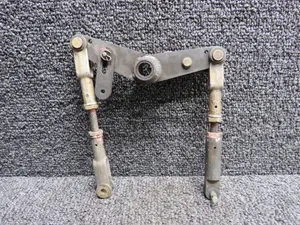
Parts listed for sale by vetted eBay sellers — confirmed on eBay at checkout.