SB-032118-B - SERVICE BULLETIN
ICON A5 · Service Bulletins
Overview
This service bulletin provides instructions for correcting an interference issue between the aileron bellcrank and aileron socket on the ICON A5 aircraft. It outlines the required actions, parts needed, and compliance timeline for affected aircraft.
- Applies to ICON A5 aircraft with specific serial numbers.
- Corrects interference between the aileron bellcrank and socket.
- Requires replacement of the wing inboard roll bellcrank if interference is found.
- No action needed if no interference is detected.
- Compliance is required within 100 hours of service or at the next maintenance event.
- Includes a parts list and installation instructions.
- Warranty reimbursement available for labor upon completion.
- Supersedes previous service bulletin SB-090817 Rev B.
Summary written by AI from the source document. Check the original before relying on it. See which parts of Sprinkle are written by AI.
Reference only, not for flight. Use the current approved manual for your aircraft. See terms, section 5.
Document
Source
Copy found at iconaircraft.com. Sprinkle hosts a reference copy with an added summary, specifications and searchable full text.
Document details
- Type ·
- Service Bulletins
- Year ·
- 2018
- File size ·
- 584 KB
- Copy found at ·
- iconaircraft.com
- Language ·
- en
What is the SB-032118-B - SERVICE BULLETIN?
The SB-032118-B - SERVICE BULLETIN is a service bulletins for the ICON A5, dated 2018.
What year was the SB-032118-B - SERVICE BULLETIN published?
The SB-032118-B - SERVICE BULLETIN — the ICON A5 service bulletins on file — is dated 2018.
Common. More common than 84% of the aircraft models we track.
Most owners only have the POH. Here's the essential set for the ICON A5.
- Pilot's Operating Handbook / AFM
- Checklist
- Maintenance Manual
- Parts Catalog (IPC)
- Systems & Wiring
- Service Bulletins on file
- Type Certificate (TCDS)
ICON A5 for sale now
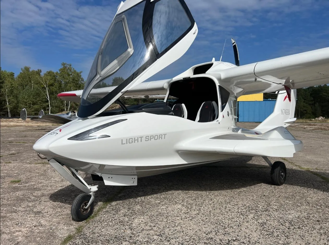
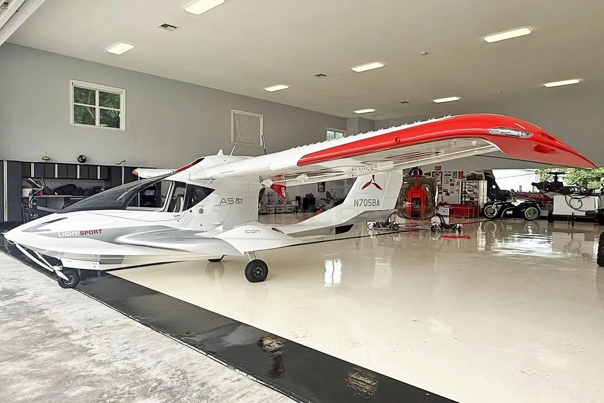
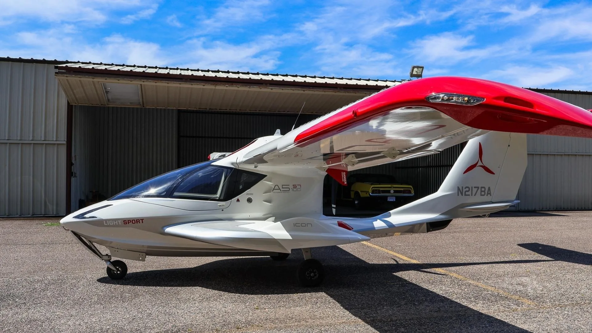
Free — save the A5 to your watchlist and track it in one place.
More ICON A5manuals & documents
Related documents
- SB-051818-C - SERVICE BULLETINICON A5 · Service Bulletins
- SERVICE BULLETIN - SB-122722-BICON A5 · Service Bulletins
- SERVICE BULLETIN - SB-011118 REV AICON AIRCRAFT A5 · Service Bulletins
- SERVICE BULLETIN SB-032420-CICON AIRCRAFT A5 · Service Bulletins
- SERVICE BULLETIN - ICON AircraftICON AIRCRAFT A5 · Service Bulletins
If you fly the ICON A5, you may also be researching these.

In this document
Required Action
Replace the wing inboard roll bellcrank if interference is detected; otherwise, no action is necessary.
Purpose
To provide instructions for installing a new design wing inboard roll bellcrank to eliminate interference.
Parts List
Includes specific part numbers and descriptions for components needed for the installation.
Installation Instructions
Step-by-step guide on how to replace the bellcrank and ensure proper rigging.
Verification
Instructions for checking aileron rigging angles and ensuring no interference remains.
Warranty
Details on how to submit invoices for warranty reimbursement for labor.
Summary written by AI from the source document. Check the original before relying on it. See which parts of Sprinkle are written by AI.
Safety notes
- Ensure the rigging pin does not interfere with the spar during unfolding.
- Contact ICON for assistance if the bearing does not smoothly rotate after installation.
- Verify that the inboard pushrod rod end bearing does not contact the roll cable terminal.
Summary written by AI from the source document. Check the original before relying on it. See which parts of Sprinkle are written by AI.
Full document text
2141 ICON Way, Vacaville, CA 95688 ‐ Tel: 707.564.4000 – www.iconaircraft.com SERVICE BULLETIN SB‐032118 REV B Confidentiality Note: The information contained in this document is confidential. Any dissemination, distribution, or copy of this document, in whole or in part, is strictly prohibited without prior written authorization by ICON Aircraft Inc. DATE ISSUED: 4/23/2018 DATE EFFECTIVE: 4/23/2018 SUPERSEDES NOTICE: When complied with, SB-090817 Rev B SB-032118 Rev A SUBJECT: Aileron bellcrank to aileron socket interference correction AIRCRAFT AFFECTED: MODEL: ICON A5 S/N: 00001-00020, 00022-00025, 00028, 00030-00032 REQUIRED ACTION: 1) If the interference condition detailed in SB-090817 rev B occurs on either wing, then replace the wing inboard roll bellcrank on both wings with new design bellcrank. 2) If the interference condition detailed in SB-090817 rev B does not occur on either wing, no maintenance action is necessary. TIME OF COMPLIANCE: At or before the next service intervention or regularly scheduled maintenance event, but not to exceed the next one hundred (100) hours’ time-in-service from the effective date above. PURPOSE: ICON is committed to designing, manufacturing, delivering, and supporting a high quality Light Sport Aircraft, providing a level of safety well beyond expectations. This Service Bulletin is to provide instructions on how to install a new design wing inboard roll bellcrank to eliminate an interference condition between the roll socket and the roll bellcrank rod end detailed in SB-090817 rev B. Not all aircraft have this condition, so it is important to inspect each aircraft for applicability. This service bulletin, when complied with, supersedes SB-090817 rev B and eliminates the reoccurring inspections of the bellcrank to roll socket interface. WARRANTY: ICON Certified Service Providers: Please submit an invoice for warranty reimbursement for labor on completion of this service bulletin. Please reference service bulletin number SB-032118. 1. 4-man hours of labor removal, installation, and rigging check. 2141 ICON Way, Vacaville, CA 95688 ‐ Tel: 707.564.4000 – www.iconaircraft.com SERVICE BULLETIN SB‐032118 REV B ICA009718-C PAGE 2 of 8 PARTS LIST: Part Number Part Description Quantity 98410A110 RETAINING RING, EXTERNAL BERYLLIUM COPPER 2 MS27640-3A BEARING, BALL, AFR AFB, HD, .190X.625X.245 2 MS27644-3 BEARING, BALL, AFR AFB, DBL ROW HD, .190X.777X.495 2 ICA009410 PIN, BELLCRANK, ROLL, WING FOLD 2 ICA012439 BELLCRANK, ROLL, WING FOLD, LH 1 ICA012440 BELLCRANK, ROLL, WING FOLD, RH 1 LOCTITE 603 RETAINING COMPOUND, CYLINDRICAL BONDING A/N LOCTITE 7471 ACTIVATOR FOR LOCTITE A/N Instructions: Special tools, fixtures, or test equipment: 1. Bearing press 2. Two - 0.1875” rigging pins PREPARATION: 1. Inspect the aircraft in accordance with SB-090817 rev B. If an interference condition is occurring, follow the steps below to correct it. If an interference condition is not occurring this service bulletin does not apply to that aircraft. 2. It is permissible to disassemble the aircraft as required to permit accessibility, inspection, adjustment, maintenance, and repair in accordance with the latest release of the Aircraft Maintenance Manual, ICA000833. 3. Fold the wings or slide them back from center wing and place them on padded work stand. 4. On each wing, remove the inboard aileron pushrod by disconnecting it from the inboard and outboard roll bellcranks. See Figure 1 and Figure 2. Retain hardware for reinstallation. 5. Remove the inboard roll bellcrank by disconnecting it from the inboard wing rib. Retain hardware for reinstallation. 2141 ICON Way, Vacaville, CA 95688 ‐ Tel: 707.564.4000 – www.iconaircraft.com SERVICE BULLETIN SB‐032118 REV B ICA009718-C PAGE 3 of 8 NAS1149C0363R MS21043-3 AN23-17 INBOARD ROLL BELLCRANK INBOARD ROLL PUSHROD WEIGHT-SAVING POCKETS FORWARD Figure 1: Inboard Roll Bellcrank and Pushrod Attachment. LH Wing Shown. 2141 ICON Way, Vacaville, CA 95688 ‐ Tel: 707.564.4000 – www.iconaircraft.com SERVICE BULLETIN SB‐032118 REV B ICA009718-C PAGE 4 of 8 AN3C10A NAS1149C0332R OUTBOARD ROLL BELLCRANK INBOARD ROLL PUSHROD MS21043-3 RIGGING PIN LOCATION Figure 2: Outboard Bellcrank and Pushrod Attachment. LH Wing Shown. 2141 ICON Way, Vacaville, CA 95688 ‐ Tel: 707.564.4000 – www.iconaircraft.com SERVICE BULLETIN SB‐032118 REV B ICA009718-C PAGE 5 of 8 INSTALLATION: 1. Assemble the inboard roll bellcrank components as shown in Figure 3 (if not already assembled from ICON). It is permissible to re-use hardware from the previously removed bellcrank except the 98410A110 clip. The MS27644-3 bearing will require a press fit. Once press fit into the bellcrank, ensure the bearing smoothly rotates. If it does not smoothly rotate contact ICON for further assistance. 2. Reinstall the inboard roll bellcrank using the retained hardware. Tighten bellcrank AN23-17 bolt to 19inlb. See Figure 1. 3. Adjust the length of the inboard push rods to 85.575” center of rod end to center of rod end by adjusting the pushrod rod ends equally, then tighten the jamb nut to 60 in-lb. Ensure that both rod ends have enough thread protrusion by visually inspecting for threads through the witness holes on the rod ends. Note: The provide push rod length provided is intended as a starting point for the rigging process, the outboard rod end and will likely need to be adjusted slightly in a step 6 below if the rigging pin cannot be easily inserted. Figure 3: Inboard Roll Bellcrank. LH Side Shown. 2141 ICON Way, Vacaville, CA 95688 ‐ Tel: 707.564.4000 – www.iconaircraft.com SERVICE BULLETIN SB‐032118 REV B ICA009718-C PAGE 6 of 8 4. Install the inboard roll pushrod using the retained hardware. It may be helpful to temporarily install the push rod on the outboard bellcrank to facilitate adjustment should it be needed in step 6. See Figure 1 and Figure 2.
Show full textShow less
5. With the wing still folded install a 0.1875” rig pin in the roll socket on the center wing as shown in Figure 4, insert it from the spar socket forward so that the wing can be inserted and locked. CAUTION: Take care to ensure that the rigging pin won’t interfere with spar during unfolding. If unsure have a helper watch this area during the unfolding process to ensure the spar will not contact the rigging pin. Figure 4: Roll socket rig pin installation 2141 ICON Way, Vacaville, CA 95688 ‐ Tel: 707.564.4000 – www.iconaircraft.com SERVICE BULLETIN SB‐032118 REV B ICA009718-C PAGE 7 of 8 6. Unfold the wing and lock it in place. Attempt to install the outboard bellcrank 0.1875” rig pin as shown in Figure 5. If it cannot be installed easily, adjust the inboard pushrod outboard rod end to allow it to install easily. Once finished retorque the jamb nut to 60 in-lb. Figure 5: Out board roll bell crank rig pin installation and adjustment. 7. Torque the bolt hardware securing the push rod rod ends to the bellcranks to 20 in-lb. 8. Unfold the wing and remove both rig pins. 9. Repeat steps 1-8 for the opposite wing. VERIFICATION: 1. Using the procedure and aileron rigging angles in the latest maintenance manual check the aileron neutral, up, and down rigging angles are correct. Record the values below. If found out of rig, contact ICON Customer support for assistance. 2. Verify that the inboard pushrod rod end bearing is not contacting the roll cable terminal in the roll cable socket. a. Obtain modeling clay or suitable formable material and form to an approximate ½ in diameter sphere/ball. 2141 ICON Way, Vacaville, CA 95688 ‐ Tel: 707.564.4000 – www.iconaircraft.com SERVICE BULLETIN SB‐032118 REV B ICA009718-C PAGE 8 of 8 b. Place that ball on the end of the inboard push tube inboard rod end. c. Unfold the wing and insert it into the center wing and lock it in accordance with the Pilot operating handbook. d. Unlock and fold the wing e. Visually verify that there is some amount of clay between the roll socket cable rod end and the inboard push rod inboard rod end. If there is still an interference present report the interference back to ICON Aircraft. MAKE THE FOLLOWING LOGBOOK ENTRY: “Service Bulletin (insert subject bulletin number) has been complied with and installation is reported to ICON Aircraft Customer Owner Support and Service”. If you need assistance relocating your A5 to your home base or temporary storage arrangements, please contact ICON Aircraft and ask for Customer Service and Support. If you are no longer in possession of this aircraft, please forward this information to the present owner/operator and notify ICON Aircraft, Owners Center at: ICON Aircraft 2141 ICON Way Vacaville, CA 95688 (855) FLY-ICON or (707) 564-4000 support@iconaircraft.com Please include the aircraft registration number, serial number, your name, and if known the contact information of the new owner/operator. 2141 ICON Way, Vacaville, CA 95688 ‐ Tel: 707.564.4000 – www.iconaircraft.com SERVICE BULLETIN SB‐032118 REV B Confidentiality Note: The information contained in this document is confidential. Any dissemination, distribution, or copy of this document, in whole or in part, is strictly prohibited without prior written authorization by ICON Aircraft Inc. SERVICE BULLETIN APPROVAL Bret Davenport Flight Sciences Manager 4/23/2018 NAME TITLE DATE NAME TITLE DATE NAME TITLE DATE