SERVICE BULLETIN - SB-122722-B
ICON A5 · Service Bulletins
Overview
This service bulletin (SB-122722-B) addresses an issue with the torque value of the jam nut on the nose landing gear (NLG) actuator rod end for the ICON A5 aircraft. It provides instructions for verifying and adjusting the torque to ensure safety and proper function.
- Applies to ICON A5 aircraft with specific serial numbers.
- Focuses on the NLG actuator rod end torque.
- Proper torque range is 95-110 in-lbs.
- No action required if previous bulletin revision A was completed.
- Compliance is required at the next service intervention.
- Instructions include disassembly and reassembly steps.
- Certification can be performed by A&P mechanics or certified repair stations.
- Includes specific torque values for various components.
Summary written by AI from the source document. Check the original before relying on it. See which parts of Sprinkle are written by AI.
Reference only, not for flight. Use the current approved manual for your aircraft. See terms, section 5.
Document
Source
Copy found at iconaircraft.com. Sprinkle hosts a reference copy with an added summary, specifications and searchable full text.
Document details
- Type ·
- Service Bulletins
- Year ·
- 2025
- File size ·
- 726 KB
- Copy found at ·
- iconaircraft.com
- Language ·
- en
Specifications & performance
Extracted from this document.
Specifications
- Fwd hose clamp torque in (lb) ·
- not specified
- Limit switch nut torque in (lb) ·
- 14 or 20
- Actuator hardware torque in (lb) ·
- 53
- Nlg actuator torque range in (lb) ·
- 95-110
What is the SERVICE BULLETIN - SB-122722-B?
The SERVICE BULLETIN - SB-122722-B is a service bulletins for the ICON A5, dated 2025.
What year was the SERVICE BULLETIN - SB-122722-B published?
The SERVICE BULLETIN - SB-122722-B — the ICON A5 service bulletins on file — is dated 2025.
Common. More common than 84% of the aircraft models we track.
Most owners only have the POH. Here's the essential set for the ICON A5.
- Pilot's Operating Handbook / AFM
- Checklist
- Maintenance Manual
- Parts Catalog (IPC)
- Systems & Wiring
- Service Bulletins on file
- Type Certificate (TCDS)
ICON A5 for sale now
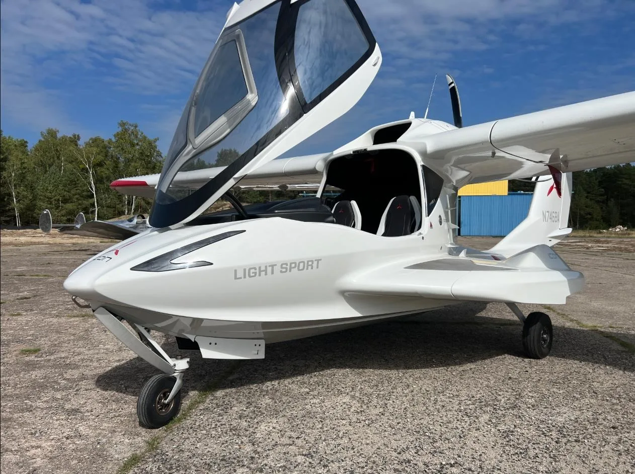
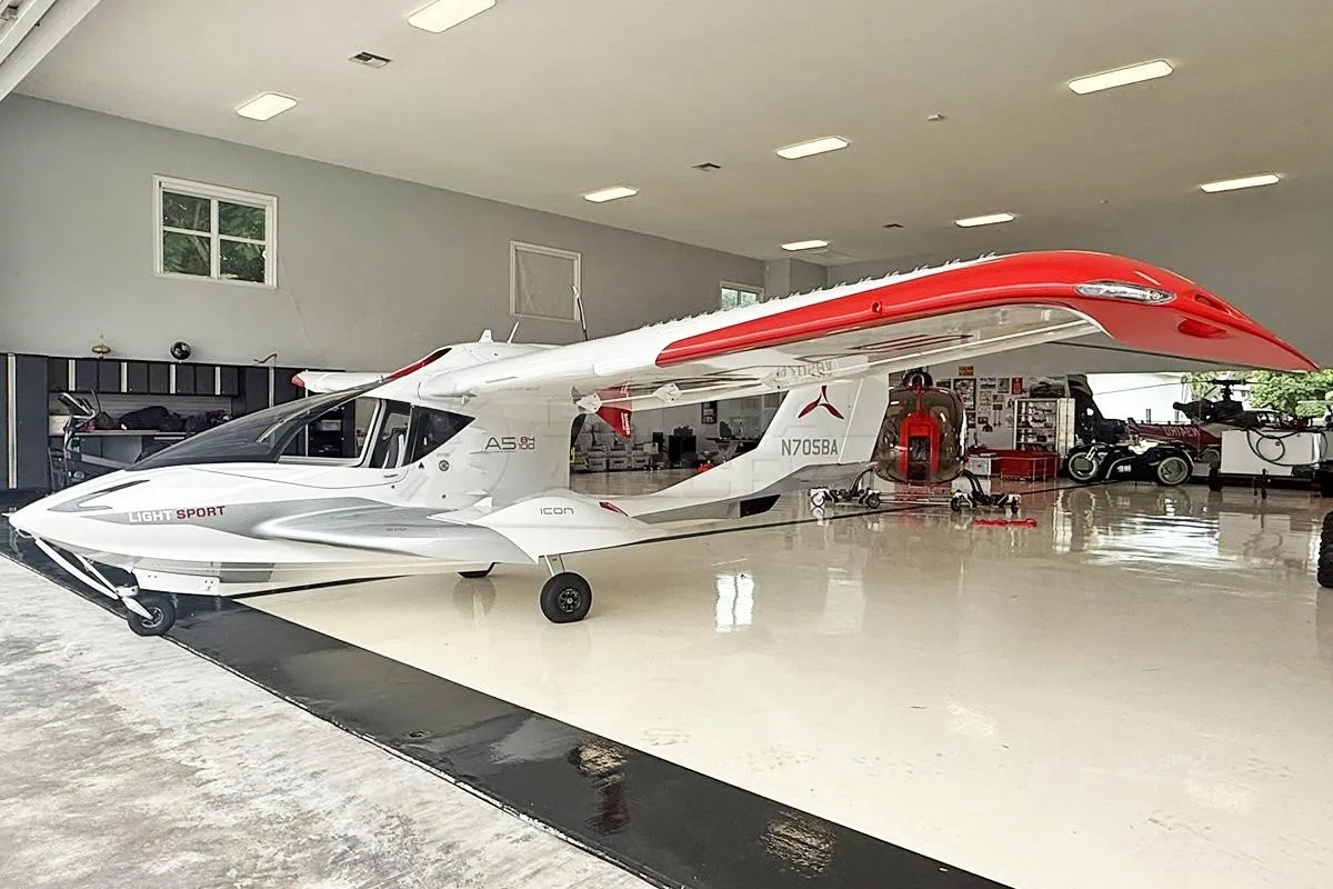
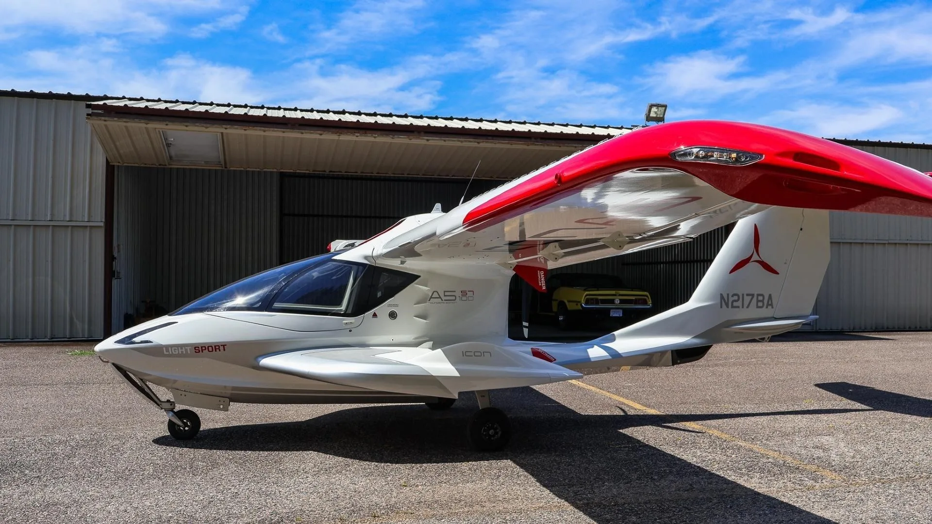
Free — save the A5 to your watchlist and track it in one place.
More ICON A5manuals & documents
Related documents
- SERVICE BULLETIN SB-032420-CICON AIRCRAFT A5 · Service Bulletins
- SB-032118-B - SERVICE BULLETINICON A5 · Service Bulletins
- SB-051818-C - SERVICE BULLETINICON A5 · Service Bulletins
- SERVICE BULLETIN - SB-011118 REV AICON AIRCRAFT A5 · Service Bulletins
- SERVICE BULLETIN - ICON AircraftICON A5 · Service Bulletins
If you fly the ICON A5, you may also be researching these.

In this document
Purpose
The bulletin identifies an issue with the torque value of the NLG jam nut and provides inspection and adjustment instructions.
Required Action
Verify the current torque level of the jam nut on the NLG actuator rod end and apply proper torque if necessary.
Instructions
Detailed steps for inspection and adjustment of the NLG actuator, including safety precautions.
Revision History
Details the changes made from revision A to B, including added steps and clarifications.
Assemblies and Parts
Lists required parts and materials for the inspection and adjustment process.
Compliance
Specifies that compliance is required at the next service intervention.
Summary written by AI from the source document. Check the original before relying on it. See which parts of Sprinkle are written by AI.
Safety notes
- Do not allow the aircraft to tip back during inspection.
- Failure to remove the limit switch assembly may cause damage.
- Ensure proper torque is applied to avoid malfunction.
- Use threadlocker as specified to secure components.
Summary written by AI from the source document. Check the original before relying on it. See which parts of Sprinkle are written by AI.
Full document text
2141 ICON Way, Vacaville, CA 95688 ‐ Tel: 707.564.4000 – www.iconaircraft.com SERVICE BULLETIN SB-122722-B FORM ICA009718-E PAGE 1 of 6 ID NUMBER & REVISION: SB-122722-B SUBJECT: NLG Actuator Rod End Torque RELEASE DATE: 31 October 2025 EFFECTIVE DATE: 27 December 2022 SUPERSEDES NOTICE: SB-122722-A AIRCRAFT AFFECTED: MAKE & MODEL: ICON A5 SERIAL NUMBERS: 00004 – 00015, 00017 – 00024, 00026 – 00074, 00076 – 00137, 00139, 00141 – 00142, 00144 – 00145, 00148 – 00150, 00152 – 00159, 00161, 00163, 00166 REQUIRED ACTION: Verify the current torque level of the jam nut on the rod end of the nose landing gear (NLG) actuator. If proper torque not present, apply proper torque. Note: If Service Bulletin revision A was completed, no further action is required. Note: If the NLG actuator was replaced after the Effective Date of this Service Bulletin, no further action is required. TIME OF COMPLIANCE: At the next service intervention REVISION HISTORY: A Initial Release B Add steps 3 and 13 to disconnect limit switches prior to releasing leg. Add notes to Required Action to clarify effectivity. LEVEL OF CERTIFICATION REQUIRED (any level checked can perform task): ☐ Pilot/Owner ☒ A & P ☐ LSA Repairman – Inspection ☒ Certified Repair Station ☒ LSA Repairman – Maintenance ☒ Manufacturer PURPOSE: ICON Aircraft has identified an issue with the torque value of the Nose Landing Gear (NLG) jam nut on the rod end of the NLG actuator. ICON discovered that the jam nut may have been under torqued during manufacturing. This Service Bulletin provides inspection and adjustment instructions to correct the issue. ASSEMBLIES AND PARTS: PART NUMBER DESCRIPTION QUANTITY ALTERNATE PART NUMBER DESCRIPTION ICA012080 INSPECTORS LACQUER, ANTI SABOTAGE, YELLOW A/N S73HW2-100-043 RETAINING RING, CRES, .438X.025 1 ICA012078 LUBRICANT, GENERAL PURPOSE A/N 2141 ICON Way, Vacaville, CA 95688 ‐ Tel: 707.564.4000 – www.iconaircraft.com SERVICE BULLETIN SB-122722-B FORM ICA009718-E PAGE 2 of 6 MOLYKOTE G-4700 LUBRICANT, MOLY-LITHIUM SYNTHETIC GREASE, BLACK A/N LOCTITE 222 THREADLOCKER, ACRYLIC, REMOVABLE LOW STR, PURPLE A/N INSTRUCTIONS: It is permissible to disassemble the aircraft as required to permit accessibility, inspection, adjustment, maintenance, and repair in accordance with the latest release of the Aircraft Maintenance Manual. Inspection and Repair 1. Raise the nose of the aircraft so that the nose gear is clear of the ground. a. Place foam blocks underneath the cockpit, aft of the NLG doors. CAUTION: Do not allow the aircraft to tip back, causing the tail of the aircraft to strike the ground 2. Remove the MLG fuse. 3. For aircraft with mechanical limit switches, loosen the two nuts securing the limit switch bracket assembly to the studs. Remove the switch and bracket assembly. CAUTION: Failure to remove the switch assembly prior to releasing the NLG leg may result in damage to the limit switch arms. Figure 7 Mechanical Limit Switches 4. Remove screw retaining NLG Door as shown in Figure 1. Retain removed hardware for reinstallation. 2141 ICON Way, Vacaville, CA 95688 ‐ Tel: 707.564.4000 – www.iconaircraft.com SERVICE BULLETIN SB-122722-B FORM ICA009718-E PAGE 3 of 6 Figure 1 Remove Forward NLG Door 5. Release NLG leg from NLG drag link by removing NLG wrist pin and retaining ring, see Figure 2 for reference. Discard retaining ring, retain pin for reinstallation. Figure 2 Release NLG Leg 6. Retract Actuator enough to get access to Actuator Boot FWD hose clamp, see Figure 3. a. Remove FWD hose clamp, retain for reinstallation. NLG leg (Reference) Screw Loctite 222 Bushing Washer Post FW Retaining ring Wrist Pin, NLG MOLYKOTE G-4700 Bellcrank Drag Link 2141 ICON Way, Vacaville, CA 95688 ‐ Tel: 707.564.4000 – www.iconaircraft.com SERVICE BULLETIN SB-122722-B FORM ICA009718-E PAGE 4 of 6 Figure 3 FWD Hose Clamp and Actuator Rod End 7. Slide boot (see Figure 3) back to expose NLG actuator rod end. 8. Remove FWD Actuator Bolt to validate Torque at FWD actuator Rod End, see Figure 4 for reference a. Make note not to remove the bushing. b. Verify and note the torque level on the jam nut. Figure 4 FWD Actuator Bolt Install 9. If the torque level of the jam nut is outside the allowable range (95-110 in-lbs) then: a. Bottom the rod end onto the thrust tube. See Figure 5. b. Torque the jam nut to 95-110 in-lbs. SECTION VIEW BOTTOM VIEW FWD Bellcrank FWD hose clamp FWD actuator Rod End NLG Actuator Boot Bushing MOLYKOTE G-4700 FWD Actuator Bolt Apply Torque stripe on threads Washer 2141 ICON Way, Vacaville, CA 95688 ‐ Tel: 707.564.4000 – www.iconaircraft.com SERVICE BULLETIN SB-122722-B FORM ICA009718-E PAGE 5 of 6 Figure 5 NLG Actuator Rod End Jam Nut 10. Reinstall actuator boot using retained FWD hose clamp. a. Position the forward end of the boot on the rod end as close to the rod as possible and secure the FWD hose clamp. Note orientation of the clamp seen in Figure 4. b. Torque the FWD hose clamp until there is a rise in torque then ¼ turn more. Verify NLG boot is not twisted as shown in Figure 6. Figure 6 NLG Boot Installation 11. Reinstall hardware securing actuator to bellcrank. a. Verify bushing is installed. b. Torque hardware to 53 in-lbs, see Figure 4. 12. Apply Molykote to the wrist pin and re-install through the NLG leg and NLG drag link as shown in Figure 2. a. Secure the wrist pin using 1x new S73HW2-100-043 retaining ring. Jam Nut 2141 ICON Way, Vacaville, CA 95688 ‐ Tel: 707.564.4000 – www.iconaircraft.com SERVICE BULLETIN SB-122722-B FORM ICA009718-E PAGE 6 of 6 13. If applicable, reinstall limit switch bracket assembly (Figure 7): a. Using isopropyl alcohol, clean surfaces where lubricant will be applied. b. Apply ICA012078 Tef-Gel to the threads of the studs. c. Install limit switch assembly onto studs with 2x NAS1149CN832R washers and 2x MS21043-08 nuts torqued to 14 in-lb (for 8-32 studs), or with 2x NAS1149C0332R
Show full textShow less
washers and 2x MS21043-3 nuts torqued to 20 in-lb (for 10-32 studs). 14. Verify NLG Actuator rig for the down position in accordance with applicable Maintenance Manual Section. a. For ASN 00001 – 00020: 100419, Nose Landing Gear (NLG) Rigging and Check, Landing Gear Down. b. For ASN 00021+: 100429, Nose Landing Gear (NLG) Rigging and Check, Landing Gear Down. 15. Verify NLG Actuator rig for the up position in accordance with ICON Aircraft maintenance manual section 100430, Nose Landing Gear (NLG) Rigging and Check, Landing Gear Up. 16. Reinstall NLG door using retained hardware, see Figure 1. a. Using Isopropyl alcohol, clean the threads of the screw where threadlocker will be applied. b. Apply Loctite 222 threadlocker to the threads of the screw. c. Deflect spring until it rests in the upper door edge. i. The spring will press the door against the NLG leg. d. Install the door to the NLG leg as shown using specified hardware. i. Ensure that no edge of the spring rests on the door. e. Install and torque the screw to 8 +/- 2 in-lb. 17. Reinstall the MLG fuse. 18. In accordance with the ICON Aircraft maintenance manual, reinstall items that were removed from the aircraft. Make the following logbook entry: “I hereby certify the inspection and repair has been completed in accordance with Service Bulletin (SB- 122722-B, NLG Actuator End Torque) and all the referenced documents. Potentially unclear procedures have been clarified with ICON Aircraft (ref. FAA Exemption 10829D)”. For aircraft registered outside the U.S., omit “(ref. FAA Exemption 10829D)”. If you have questions, comments, or concerns about this Service Bulletin and/or if you are no longer owner/operator of this aircraft, please forward this information to the present owner/operator and notify ICON Aircraft at: ICON Aircraft 2141 ICON Way, Suite 100 Vacaville, CA 95688 (707) 564-4000 support@iconaircraft.com Please include the aircraft registration number, serial number, your name, and if known the contact information of the new owner/operator.