Airworthiness Directives
Piper J-4 Cub Coupe · Airworthiness Directives
Overview
This document outlines airworthiness directives applicable to the Piper J-4 Cub Coupe, detailing necessary modifications and inspections to ensure the aircraft's safety and compliance with federal regulations. It serves as a critical reference for aircraft owners and operators, emphasizing the importance of maintaining airworthiness standards. The directives are mandatory and must be adhered to in order to keep the aircraft in a condition for safe operation. The document also discusses the process for issuing these directives, compliance requirements, and the role of the Civil Aeronautics Administration (CAA) in overseeing aircraft safety.
- Airworthiness directives are mandatory for the Piper J-4 Cub Coupe to ensure safety.
- Compliance with these directives is essential to maintain the aircraft's airworthiness.
- Inspection intervals and modification requirements are specified in the directives.
- Manufacturer's service bulletins provide additional guidance but are not mandatory.
- Aviation Safety agents are responsible for verifying compliance with airworthiness directives.
Document
Source
Originally published by archives.federalregister.gov. Sprinkle hosts a reference copy with an added summary, specifications and searchable full text.
Document details
- Type
- Airworthiness Directives
- Year
- 1950
- Pages
- 68
- File size
- 13 MB
- Publisher
- archives.federalregister.gov
Most owners only have the POH. Here's the essential set for the Piper J-4 Cub Coupe.
- Pilot's Operating Handbook / AFM
- Checklist
- Maintenance Manual
- Parts Catalog (IPC)
- Systems & Wiring
- Service Bulletins
- Type Certificate (TCDS)
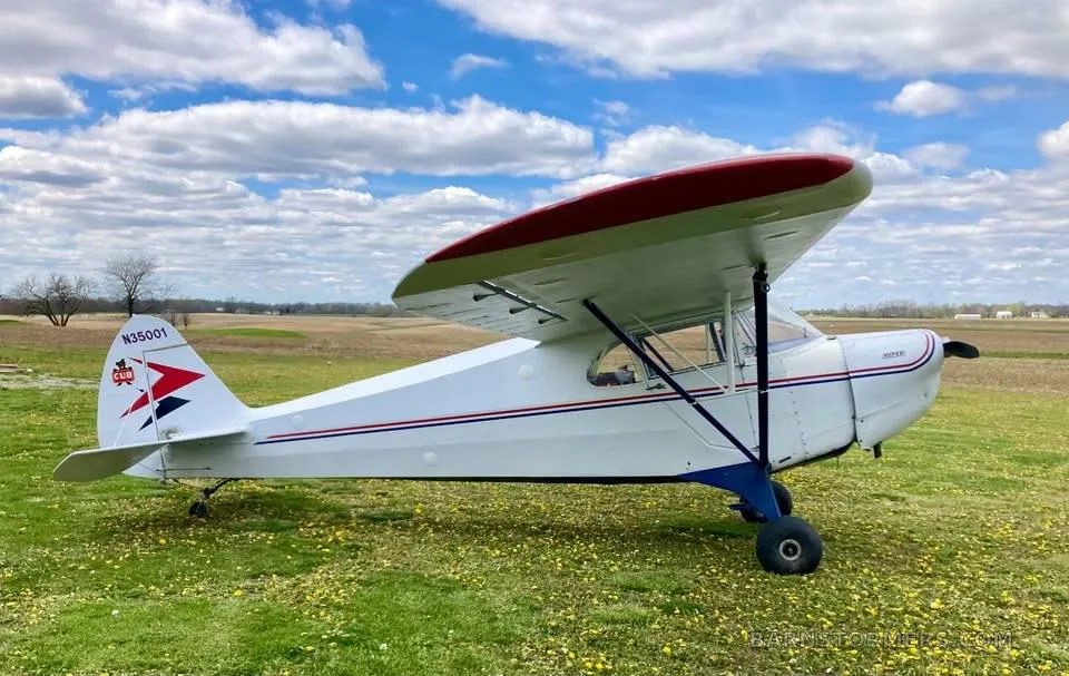
Piper J-4 Cub Coupe for sale now
Free — save the J-4 Cub Coupe to your watchlist and track it in one place.
More Piper J-4 Cub Coupemanuals & documents
- Vintage Airplane - January 1993Other Documents
- Restoration of the Piper J-4AWeight And Balance
- Parts Catalog for Piper J-4 Cub CoupeParts Catalog
- LUFTDYKTIGHETSPABUDService Bulletins
- Normal Procedures for the Piper J-4 Cub CoupeNormal Procedures
- Sensenich Fixed Pitch Wood Propellers Installation List for Type Certified AircraftFlight Manual
- Weight & Balance for the Piper J-4 Cub CoupeWeight And Balance
If you fly the Piper J-4 Cub Coupe, you may also be researching these.



In this document
Introduction to Airworthiness Directives
The introduction explains the purpose of airworthiness directives, which are mandatory modifications required to remedy defects affecting aircraft safety. It describes the authority of the CAA to issue these directives and the process involved in their creation and publication.
Compliance Requirements
This section outlines the obligations of aircraft owners and operators to comply with airworthiness directives. It specifies that failure to comply renders the aircraft unairworthy and details the consequences of non-compliance.
Inspection Intervals and Modifications
The document provides guidelines on inspection intervals and the necessary modifications to be made to the aircraft. It emphasizes that these modifications are essential for maintaining airworthiness and outlines how compliance dates are determined.
Manufacturer's Service Bulletins
This section discusses the role of manufacturer's service bulletins in relation to airworthiness directives. It clarifies that while compliance with service bulletins is not mandatory, they provide valuable information for operators regarding necessary changes.
Determination of Compliance
The document explains how compliance with airworthiness directives is verified by Aviation Safety agents. It emphasizes the importance of maintaining accurate records of compliance in the aircraft's logbook.
Safety notes
- Failure to comply with airworthiness directives can result in the aircraft being deemed unairworthy.
- Modifications must be completed by the specified compliance dates to ensure safety.
Full document text
3870 employment opportunities, the Commis sion shall: (a ) Keep currently advised of em ployment and housing opportunities in the United States, its territories and- possessions; (b) Consider and process assurances to promote effective resettlement in areas and locations where housing and employment opportunities are available; (c) Seek the advice and guidance of State Commissions or Committees on Displaced Persons and other public agencies and private agencies regarding the acceptability of assurances as to suitability of employment, housing, proper care and public charge repre sentations; (d) Establish and maintain working relationships with State Commissions or Committees on Displaced Persons, other appropriate public agencies and private agencies for the purpose of orderly and effective resettlement, throughout the United States, its territories and posses sions, of persons who immigrate under those provisions of the act which the Commission administers; (e) Disseminate among persons se lected by the Commission, through ori entation courses, lectures, films, and other appropriate means, facts and data concerning the history, customs, tradi tions, and geography of the United States, better to enable such persons to understand the obligations they assume under the act and to become adjusted to life in the United States, and seek the cooperation of public and private agen cies to achieve this objective. £710.5 Reports "by certain immigrants. Every eligible displaced person, except an eligible displaced person who shall have derived his status because of being the spouse or an unmarried dependent child under twenty-one years of age of an eligible displaced person, and eligible displaced orphans and orphans as de fined in section 2 (f ) of the act, who shall be admitted to the United States shall report in such form as may be approved or required by the Commission, on the first day of January and on the first day of July of each year until he shall have made four reports to the Commission. The report shall set forth the employ ment, place of employment, and resi dence of the person reporting and of the members of his family, and shall furnish such other information as the Commis sion may require. If the term of the Commission expires before the four re ports have been submitted, the remain ing number of the required reports shall be submitted to the Attorney General. If a person who is required to submit such report enters the United States within 60 days prior to either the first day of January or the first day of July, the first report need not be made until the next date on which a report is re quired to be made. This order shall become effective on the date of its publication in the F ederal R egister. Compliance with the provi sions of section 4 (a ) of the Administra tive Procedure Act (60 Stat. 238; 5 U. S. C. 1003) as to notice of proposed rule making is found to be contrary to the public interest because Public Law 774, 80th Congress (62 Stat. 1009), as RULES AND REGULATIONS amended by the act of June 16, 1950, which is implemented by these regula tions became effective on June 16, 1950, and the execution of functions of the Displaced Persons Commission under that statute would be unduly impeded by such notice. For the same reason it is found that the provisions of section 4 (c) of the Administrative Procedure Act providing for delayed effective date are inapplicable. H a r r y N. R o sen field , Acting Chairman, Displaced Persons Commission. [F. R. Doc. 50-5325; Filed, June 16, 1850; 1:18 p. m.] TITLE 32— NATIONAL DEFENSE Chapter VII— Department of the Air Force Subchapter G— Personnel P art 885— A p p o in t m e n t of S econd L ie u t e n a n ts F r o m D is t in g u is h e d M il it a r y G raduates, A ir F orce R eserve O f f i cers’ T r a in in g Corps Regulations contained in §§ 885.1 to 885.8, inclusive (14 F. R. 6130), are hereby revised. Pursuant to the authority conferred by sections 207 (f) and 203 (e) of the N a tional Security Act (61 Stat. 503, 504; 5 U. S. C. Sup. 626 ( f ), 626c ( e ) ), Trans fer Order 2, October 1, 1947 (12 F. R. 6736), and cited laws, the following regulation is hereby prescribed: Sec. 885.1 Purpose. 835.2 Command responsibility. 885.3 Distinguished military student. 885.4 Distinguished military graduate. 885.5 Eligibility. 885.6 Application. 885.7 Field processing. 885.8 Processing by Headquarters United States Air Force. 885.9 Notification of nonselection. 885.10 Tender of appointments. Au t h o r it y : §§ 885.1 to £85.10 issued under secs. 502, 506, 61 Stat. 883, 890; 10 U. S. C. Sup. 506, 506c. D erivation: AFR 36-15. § 885.1 Purpose. The regulations in this part prescribe the procedure where by distinguished military graduates of the Air Force Reserve Officers’ Training Corps may be commissioned as second lieutenants in the Regular Air Force. § 885.2 Command responsibility— (a ) Air Force commanders. Air Force com manders responsible for the implemen tation of the regulations in this part in their respective areas are: (1) The commanders of the numbered air forces of the Continental Air Com mand in the Zone of Interior. (2) The senior Air Force commander in each oversea command. (b) Professors. Professors of air science and tactics are responsible to the appropriate Air Force commander for the administration of this program. § 885.3 Distinguished military stu dent— (a ) Definition. A person desig nated by the professor of air science and tactics who: (1) Has completed or has been cred ited with Air Science I and Air Science H in accordance with existing regulations and has completed, or is scheduled to complete, within 15 day's, one year of the advanced course, Air Force Reserve O f ficers’ Training Corps. (2) Has an academic standing among the upper third of the students within his Air Force Reserve Officers’ Training Corps class pursuing the same special ized option and, unless a graduate stu dent, has an academic standing among
Show full textShow less
the upper half of all students in the in stitution pursuing the same academic > major and scheduled to graduate the same school year. (3) Possesses outstanding qualities of military leadership, high moral charac ter, and definite aptitude for the mili tary service. (4) Has distinguished himself by demonstrated leadership through his ac complishments while participating in recognized campus activities. (b ) Time of designation. The profes sor of air science and tactics will desig nate the distinguished military students from among qualified students who are scheduled to complete the first year of advanced course, Air Force Reserve O f ficers’ Training Corps, within 15 days. (c) Designation. The professor of air science and tactics will obtain the writ ten opinion of the president or other appropriate officials of the institution prior to the. announcement of specific students designated as distinguished military students. He will notify the distinguished military students of their designation by letter and insure, by con ducting an orientation on the provisions of this part, that they are aware of the opportunity to compete for a Regular Air Force commission. He may withdraw any such designation any time prior to graduation. When justification exists he also may designate additional dis tinguished military students during their last academic year provided that such designation is accomplished in sufficient time to permit those students to apply for appointment during one of the ap plication periods outlined in § 885.6 (c) (1) and (2), prior to becoming eligible for designation as distinguished military graduates. N o t e : Students designated as distin guished military students prior to May 1, 1950, will continue to be processed under the provisions of §§885.1 to 885.8 (14 F. R. 6150). § 885.4 Distinguished military grad uate— (a ) Definition. A person desig nated by the professor of air science and tactics or appropriate Air Force com mander who: (1) W as designated a distinguished military student and has maintained the standards required of a distinguished military student during the period be tween designation and date of gradua tion." (2) Has completed the advanced course, Air Force Reserve Officers’ Train ing Corps. (3) Has been graduated by a recog nized college or university with a baccalaureate degree. (b) Time of designation. Designa tion of distinguished military graduates will be accomplished as follows: Saturday, June 17, 1950 FEDERAL REGISTER 3871 (1) Distinguished military students who have fulfilled thè requirements of paragraph- (a ) of this section will be designated by the professor of air science and tactics on date of graduation. (2) Distinguished military students who have fulfilled all the requirements of paragraph (a ) of this section, except completion of the Air Force Reserve Officers’ Training Corps summer camp, will be designated by the professor of air science and tactics upon satisfactory completion of such camp. (3) In instances where a distinguished military student has successfully com pleted the advanced course, Air Force Reserve Officers’ Training Corps, prior to graduation, and graduation is from a recognized institution having no Air Force Reserve Officers’ Training Corps unit, the designation will be made by the appropriate Air Force commander. The Air Force commander, upon the student’s graduation, will assure that the student being designated has maintained the prescribed standards during the in terim between completion of the ad vanced course, Air Force Reserve Officers’ Training Corps, and graduation. (c) Designation. Each distinguished military student will be notified of desig nation as a distinguished military graduate by letter, on date of successful completion of the requirements. § 885.5 JEligibility. Each candidate, at time of appointment, must: (a) Be a distinguished military grad uate. (b) Be at least 21 years of age. Dur ing the present emergency, a selected candidate who has not reached the age of 21 years on or prior to the scheduled date of appointment will be appointed a second lieutenant in the United States Air Force Reserve and, upon applica tion, will be ordered to extended active duty. A person appointed a Reserve of ficer under this provision, upon attain ment of his 21st birthday, normally will be appointed in the Regular Air Force if at that time he is physically qualified. (c) Not have passed his 27th birthday on date of appointment in the Regular component, except that an applicant who served in the Armed Forces of the United States prior to September 2,1945, may apply: Provided, That he will not exceed the 30th anniversary of his birth on July 1st of the calendar year in which he submits his application. (d ) Be physically qualified for ap pointment in the Regular Air Force as determined by a final type physical examination. (e) Have a record free of conviction by any type of military or civil court for other than a minor traffic violation. Re quest for waiver may be made in case of other minor violations which are non recurrent and which are not considered prejudicial to performance of duty as an officer. The granting of a waiver will not be considered in the case of any per son who has been convicted of a crime involving moral turpitude. Appropriate Air Force commanders are authorized to take final action on such requests. (f) Not be nor have been a conscien tious objector. (g) Not be nor have been a member of any foreign or domestic organization, association, movement, group, or com bination of persons advocating subver sive policy or seeking to alter the form of Government of the United States by unconstitutional means. § 885.6 Application— (a ) By whom submitted. Under the provisions of this part, applications for Regular appoint ment may be submitted only by dis tinguished military students. (b ) Completion of application. Each distinguished military student desiring appointment in the Regular Air Force will submit to the professor of air science and tactics a formal application on Air Force Form 17, “Application for Com mission in United States Air Force”, in duplicate, with a photograph of himself, not less than three by five inches in size with his and the institution’s name on back. He also will submit a loyalty statement in accordance with the pro visions of Part 886 of this chapter (14 F. R. 6979) and attach to the application a copy of the letter designating him a distinguished military student and a transcript of college credits earned prior to submission of application In in stances where the policy of the institu tion is not to give a transcript of credits to the student he will take the necessary action to have the transcript forwarded direct to the Director of Training, Head quarters United States Air Force, At tention: Officer Initial Procurement Branch, Personnel Procurement Divi sion, Washington 25, D. C., to arrive not later than 15 days after the close of the application period. Applicants may se lect as second choice, service in Depart ment of the Army. Applicants desiring to make a second choice will indicate this fact and will show under “Remarks” (item (17) of Air Force Form 17), the arm or service in which they desire to serve. (c) Submission of application. At the time of application the student must have one school year or less remaining until graduation. The student will sub mit his application to the professor of air science and tactics during one of the following periods: (1) During the period of October 1st to 15th which is the normal application period for students scheduled to gradu ate during May and June of the fol lowing year. (Students submitting applications during this period normally will be notified of selection or nonselec tion on or about January 30th.) (2) During the period of March 15th to 30th which is the normal application period for students scheduled to grad uate during the following December and January. (Students submitting, appli cations during this period normally will be notified of selection Or nonselection on or about June 30th.) (d ) Change of address. If an appli cant changes his address subsequent to the submission of his application and prior to receipt of notification of selec tion or nonselection he will be responsi ble for reporting the change, in writing, through the professor of air science and tactics and the appropriate Air Force commander to the Director of Training, Headquarters United States Air Force, Attention: Officer Initial Procurement Branch, Personnel Procurement Divi sion, Washington 25, D. C. § 885.7 Field processing— (a ) Bio graphical test evaluation reports. Prior to the processing of applicants by the interview board, the professor of air science and tactics will supervise the execution of the biographical test by each applicant and obtain three com pleted forms W D AGO PR T 708, “ROTC Evaluation Report, Answer Sheet,” for each applicant. Two of the evaluation reports will be accomplished by members of the Air Force Reserve Officers’ Train ing Corps detachment, and one by the Air Force Reserve Officers’ Training Corps summer camp commander or his representative. If the student is desig nated subsequent to his attendance at summer camp, or does not attend sum mer camp until after completing the second year of the advanced course, Air Force Reserve Officers’ Training Corps, the third copy of the evaluation report will be submitted by a member of the Air Force Reserve Officers’ Training Corps detachment. If practicable, the professor of air science and tactics will submit one of the evaluation reports; however, all rating personnel must have had an adequate opportunity to observe the applicant. (b ) Appointment and composition of the interview board. The appropriate Air Force commander will appoint boards of officers to interview the applicants. Each board will be composed of a mini mum of three Air Force officers, a ma jority of whom will be commissioned in the Regular component. The professor of air science and tactics and members of the military staff of a particular insti tution will not be utilized as members of the board appointed to interview candi dates from that institution. (c) Physical examination. Each ap proved applicant will be notified of his selection and of the time and place to report for physical examination. De termination of physical qualification or disqualification will be made by Head quarters United States Air Force. § 885.8 Processing by HeadQuarters United States Air Force. Upon receipt of applications and screening materials, composite scores for each applicant will be computed and transmitted with the documents to the Air Force Personnel Board for final selection. § 885.9 Notification of nonselection. Candidates who have not been selected for appointment will be notified through the appropriate Air Force commander and the professor of air science and tactics. § 885.10 Tender of appointments. The Director of Training, Headquarters United States Air Force will officially tender appointments to approved appli cants after receipt of letters designating them distinguished military graduates and determination of their physical qualification by the Surgeon General, United States Air Force. [ se al! E. H. N e l s o n , Colonel, U. S. Air Force, Deputy Air Adjutant General. [P. R. Doc. 50-5230; Piled, June 16, 1950j 8:45 a. m.] 3872 TITLE 14— CIVIL AVIATION Chapter I— Civil Aeronautics Board Subchapter A— Civil Air Regulations [Supplement 1] P art 1— A ir w o r t h in e s s C ertificates AIRWORTHINESS DIRECTIVES The following policies and rules, which require modifications of aircraft for the purpose of remedying defects affecting airworthiness, are hereby adopted. They shall become effective upon publication in the F ederal R egister unless otherwise indicated, in order to promote safety of the flying public. Compliance with the notice, procedures, and effective date provisions of section 4 of the Adminis trative Procedure Act would be imprac ticable and contrary to the public inter est and, therefore is not required. § U2-1 Airworthiness directives ( CAA policies and rules which apply to § L 2 ). See Appendix A of this part. A p p e n d ix A— A ir w o r t h in e s s D irectives 1. Introduction to airworthiness direc tives (CAA policies) — (a) General. (1) The Civil Aeronautics Act of 1938, as amended, empowers the Administrator of Civil Aer<?nautics to issue type certificates for aircraft after he determines that the aircraft is of proper design, material, specification, construction, and perform ance for safe operation, and that it meets the minimum standards pre scribed by the Board. If the Admin istrator finds that the aircraft conforms to the type certificate therefor, and, after inspection, that the aircraft is in a condition for safe operation, upon ap plication by the registered owner, he will issue an airworthiness certificate. (2) The Civil Air Regulations pro vide that an aircraft shall not be flown unless it is in an airworthy condition. Normally, an aircraft will be considered airworthy if it is maintained at or above the airworthiness standards required for the original issuance of the airworthi ness certificate. From time to time, however, service experience brings to light certain difficulties with respect to a particular make and model aircraft, which may affect its airworthiness. In formation regarding such difficulties comes to the attention of the CAA from various sources. For example, reports may be received from mechanics, oper ators, manufacturers, Aviation Safety agents, and occasionally, from foreign governments. These reports are re ferred to the regional office which deals with the manufacturer of the aircraft. The regional office determines what cor rective action, if any, is to be taken. Frequently the issuance of a service bul letin by the manufacturer is adequate, and the matter is closed. (3) When the difficulty affects the airworthiness of the aircraft, it some times becomes necessary to modify the specifications on which the type certi ficate is based. If sufficient justification for such action exists, the public is ad vised of the change in specifications through the medium of airworthiness directives. These directives are pre pared in the regional office, after dis- RULES AND REGULATIONS cussion with the manufacturer.* They are then forwarded to the Washington office for further consideration, clear ance, and publication. The airworthi ness directive, when finally issued, specifies the modifications and inspec tions necessary to preserve’the airwor thiness of the aircraft, and also the compliance dates by which the modi fications and inspections must be accom plished. The airworthiness directive is therefore mandatory, and aircraft which are not modified and inspected in ac cordance therewith are considered by the CAA to be unairworthy. (b) Letters to manufacturers. If the subject matter of an airworthiness direc tive proposed by a regional office does not appear to warrant compulsory action, an airworthiness directive will not be issued. In such cases a letter may be addressed to the manufacturer, indicat ing the desirability of corrective action, and recommending that steps be taken to remedy the difficulty. Such recom mendations are not considered manda tory. (c) Compliance dates and inspection intervals. When the defect is one which affects the airworthiness of the aircraft immediately, inspection and modification is required at once. On the other hand, if a condition does not render the aircraft unairworthy at the time it is discovered, but it will inevitably affect airworthiness if it continues to exist, a compliance date in the future will be prescribed. This compliance date is fixed after taking into account the nature and amount of work involved, the availability of parts, recom mendations of the manufacturer and operators, and the effectiveness of oper ating restrictions which may mitigate the condition. Operating restrictions are usually temporary, and reduce or elimi nate the hazard pending completion of the required modification. (d) Extension of compliance dates. Since the availability of parts required for a given'modification is not always completely and reliably predictable, it is occasionally necessary to extend a com pliance date. This will be only done when the operator of the aircraft has demonstrated good faith in his efforts to comply, and when the delay is found to be beyond the control of the operator applying for the extension. Application for extension in such cases must always be made to the local Aviation Safety agent who will forward the application together with his recommendations to his regional office, whence the matter will be referred to the Washington office for decision on the extension. Exten sion of compliance dates can be author ized only by the Washington office of the CAA. In the interest of uniform admin istration of the airworthiness directive system, it is not considered desirable or reasonable to decentralize authority for the extension of compliance dates. Be cause of the process mentioned above, an extension of a compliance date should be requested at the earliest moment it be comes apparent that the compliance date cannot be met. Waiting until immedi ately prior to the compliance date will make it very difficult to give the request the consideration which might be neces sary in order to warrant an extension and may make it impossible to grant the extension. (e) Adjustment of inspection inter vals. Inspection intervals specified in airworthiness directives are chosen after consideration of the nature of the inspec tion, especially the frequency considered necessary for minimum safety, the man ufacturer’s recommendations, and the recommendations of any other interested parties. Such intervals are usually in round numbers and in the case of air craft that are maintained on a continu ous inspection and maintenance system, the local Aviation Safety agent is em powered to make reasonable adjustments in the intervals specified to allow com pliance by the operators at the nearest inspection period. The amount of toler ance allowed the agent is not specified in numbêr of hours or in percentage of total time, but rather is left to the discretion of the agent to decide for himself the intent and urgency of the inspection as balanced against the normal inspection periods set up for the operators to which he is assigned. (f) Equivalent modifications. The objective of an-airworthiness directive specifying a modification to an airplane is solely to correct a particular difficulty. This point cannot be emphasized too much. The only reason for issuing an airworthiness directive is to correct a difficulty discovered in service. Hence, the airworthiness directive is so written as to describe the change involved, and while it refers to the manufacturer’s service bulletin, it specifically does not require compliance with that service bul letin. In other words, the change itself is what is desired by the CAA, and the reference to the manufacturer’s service bulletin is included so that operators can obtain more complete information than can be contained in the airworthiness directive. In view of the above, it logi cally follows that the CAA will accept equivalent modifications to those set forth in the manufacturer’s'service bul letin, so long as those equivalent modifi cations actually accomplish the required effect. The Aviation Safety agent is authorized to accept such equivalent modifications, and he may do so on his own authority or he can refer the matter to his regional office for additional advice if he desires. (g ) Equivalent inspections. It is sometimes found necessary to publish an airworthiness directive covering an in spection that may already be required by the terms of the Operation Specifica tion— Maintenance of one or more air carrier operators. Where the inspection already set up in the Operation Specifi cation— Maintenance is considered by the Aviation Safety agent to be the equivalent of that specified in the air worthiness directive, and where the previously established inspection period is no longer than that specified in the airworthiness directive, the airworthiness directive may be disregarded by that operator as having already been complied with. In other words, where an inspec tion set up by an airworthiness directive is already covered by the Operation Spec ification— Maintenance, whichever is the more stringent will govern (subject to Saturday•, June 17, 1950 FEDERAL REGISTER 3873 minor adjustment as outlined above un der “Adjustment of Inspection Inter vals”). No formal notice, recording of compliance, or other paper work should be involved in such cases. (h) Determination of compliance by the affent. It is the responsibility of the Aviation Safety agent to determine that- the operator has complied with the terms of the airworthiness directive. In the case of aircraft that are maintained on a continuous inspection and mainte nance system, that does not necessarily mean that the agent must inspect per sonally each individual airplane, or that he must “sign-off” the inspection or modification. Normally the agent deter mines compliance by means of spot checks in the maintenance base and on the field and will not actually inspect each aircraft involved However, it should be pointed out that if the agent deems such personal inspection of each airplane necessary, then he may require that each airplane be presented to him individually. Ordinarily this procedure can be worked out between the operator and the local agent in such a manner as to reduce to a minimum the incon venience and paper work required. Compliance with airworthiness direc tives should be recorded in the aircraft records by making an entry in the ap propriate log book. (i) Manufacturer’s service bulletins. Manufacturer’s service bulletins for air craft are not required to be approved by the CAA, and, in fact, the CAA will ap prove only those bulletins that are the subject of an airworthiness directive or are prepared at the request of the CAA. An exception may be made when re quested by the manufacturer and when such approval will assist CAA field rep resentatives in the approval of changes made in the field. The aircraft manu facturer may issue any and all informa tion in any form he desires to the oper ators of his aircraft or to the public. In any case where a manufacturer’s service bulletin is mentioned in an airworthi ness directive, such bulletin has been approved by the CAA. Alterations or repairs made in accordance with manu facturer’s service bulletins should be approved in the field in the usual man ner for any repair or alteration. It should be noted that supplements or addenda to service bulletins, issued sub sequent to the publication of an air worthiness directive note referring to the basic service bulletin, may or may not be CAA approved. Changes covered in the supplemental bulletins are not required changes unless the airworthiness direc tive is modified to so state. In cases where a service bulletin change is to be the subject of an airworthiness directive note, the aircraft manufacturer should submit twelve copies of that bulletin to the regional office with which he has con tact. 2. Aircraft affected by airworthiness directives (CAA policies). The following table is provided for use in determining which of the airworthiness directives published in section 3 apply to particu lar aircraft. This table includes only airworthiness directives issued on or be fore April 24, 1950. A bronca Aircraft Cobp., Middletown, Ohio C ivil model Type certificate Applicable directives K C A , 65-C, S-65-0. __ :______ T C 675--------------------- 05-CA, S-65-CA _____________ T C 675--------------------- 1 65-LA________ _ ______________ 6Ö-TC, 65-TAC, YO-58 ______ Ö-58-A, 0-58-B, SO-58-B----- T C 702______ :---------- T C 728______________ T C 751_______________ T O 759_______________ T C 759_________ 11ÀC________________________ T C 761. S11AC_______________________ T C 761------ --------------- 7BCM. 11BC_ 11CC-. 15AC- S15AC T C 759_______ :____ T O 761____________ T C 796____________ T.C 802____ ________ T C 802___ ;_______ 46-36-1 (Continental piston pins). 46-36-1 (Continental piston pins), . 47-30-8 (Seat modification). 47-30-8 (Seat modification). 46-36-1 (Continental piston pins). 46-36-1 (Continental piston pins). 46-36-1 (Continental piston pins). 47- 20-1 (Gascolator bowl cleaning). 47-20-2 (Oleo piston)u 47-30-1 (L ift strut ,wing attachment fittings). 47- 30-5 (Exhaust stack inspection). 48- 4-2 (Wing rib rework). 48- 39-1 (Control stick rework). 49- 11-2 (Wing attach fitting). * 46- 36-1 (Continental piston pins). 47-20-1 (Gascolator bowl cleaning). 47-30-1 (L ift strut wing attachment fittings). 47-30-5 (Exhaust stack inspection). 47- 50-5 (Float wirepull fitting). 48- 4-2 (Wing rib rework). 48-39-1 (Control stick rework). 49- 11-2 (Wing attach fitting). 46-36-1 (Continental piston pins). 47- 20-1 (Gascolator bowl cleaning). 47-20-2 (Oleo piston). 47-30-1 (L ift strut wing attachment fittings). 47- 30-5 (Exhaust stack inspection). 48- 4-2 (Wing rib rework). 48- 13-7 (Tumbuckle fork replacement). 49- 11-2 (Wing attach fitting). 49-15-1 (Seat anchorage rework). 47-20-1 (Gascolator bowl cleaning). 47- 50-5 (Float wirepull fitting). 48- 4-2 (Wing rib rework). 48- 13-7 (Tumbuckle fork replacement). 49- 11-2 (Wing attach fitting). 49-15-1 (Seat anchorage rework). 47-20-1 (Gascolator bowl cleaning). 48-39-1 (Control stick rework). 49- 11-2 (Wing attach fitting). 47-20-1 (Gascolator bowl cleaning). 48- 4-2 (Wing rib rework).. 49- 11-2 (Wing attach fitting). 49-15-1 (Seat anchorage rework). 47- 20-1 (Gascolator bowl cleaning). 48- 4-2 (Wing rib rework). 49-11-2 (Wing attach fitting). 48-38-1 (Oil cooler installation). 48-43-2 (Continental C-146-2 engines). 48-38-1 (Oil cooler installation). 48-43-2 (Continental G-145-2 engines). Beech Aircraft Cobp., Wichita, K ans. Arm y ÁT-11, N avy SNB-1 __ 47- 6-8 (Starter solenoid and buss lead wires). n s s _ T C 757.. . 47- 6-9 (Landing gear retracting mechanism). 47-30-6 (Generator relay control switch). 47-30-7 (Trip-free circuit breaker). 47-33-3 (Tail cone drain holes). 47-33-5 (Horizontal stabilizer spar). 48- 14-3 (Wing center section spar). 48-34-1 (Stabilizer attachment fittings). 48-50-2 (Landing gear slide tube). 48-51-1 (Control wheel shaft inspection). 49- 15-3 (Fuel tank vent systems). 45-11-1 (Auto-pilot overpower valves). '45-25-1 (Three-pole-single-throw relays). D17S_ _ ' . T C 649_____ ___ 45-25-2 (Trip-free circuit breaker). 47- 6-8 (Starter solenoid and buss lead wires). 47- 6-9 (Landing gear retracting mechanism). 47-33-3 (Tail cone drain holes). 47-33-4 (Fuel tank gaskets). 47-33-5 (Horizontal stabilizer spar). 48-14-3 (Wing center section spar). 48-34-1 (Stabilizer attachment fittings). 48-50-2 (Landing gear slide tube). 48-51-1 (Control wheel shaft inspection). 49-15-3 (Full tank vent systems). 48-51-1 (Control wheel shaft inspection). t u r f, r>ian _____ T Ò 765_____ 47-33-5 (Horizontal stabilizer spar). la ia rw r T O 770- 47-33-6 (Stabilizer spar replacement). 47-33-7 (Alternate static source). 47-34-1 (Expansion type filler cap). 47-34-2 (Tail cone dram holes). 47- 34-3 (Fuel cell seal). 48— 13—1 (Generator control box insulation) 48-16-1 (Wing spar fittings). 48-34-1 (Stabilizer attachment fittings). 49-29-2 (Rudder spring bushings). 47-33-6 (Stabilizer spar replacement). T C 777- — — 47-33-7 (Alternate static source). 47-34-2 (Tail cone drain holes). 47-51-10 (Birdproof windshield). 48-16-1 (Wing spar fittings). 48-34-1 .(Stabilizer attachment fittings). 49-29-2 (Rudder spring bushings). 47-47-7 (Engine identification plate). 47-47-8 (Fuel iine chafing). 48- 8-1 (Starter rework). 49- 2-4 (Oil pump rework). 49- 4-1 (Aileron control chain). 49-26-1 (Trailing antenna rework). 49-28-2 (Fuel booster pump removal). 49-31-1 (Emergency fuel pump “ O” rings). 49-48-1 (Thompson fuel pump). Bell Aieceaft Coep ., N iagaba Falls , N. Y. C ivil model Type certificate 47B, 47B-S, 47B2, 47B2-S. H T C l ____________ 47B3 ____ H T C l ___________ 47D ________ _ ______ Ö T C 1 ________________ 47D1 _____ __ _______ __________ H T C l Applicable directives ___ 47-32- 1 (Stabilizer damper frame clamp rework). 47-32- 2 (Ballast installation). 47-32- 3 (Tail rotor control pedal pawl stop). 47-32- 4 (Anti-torque rotor blades placard). 47-32- 5 (Main rotor mast spinner). 47-32- 6 (Main rotor hub pillow blocks). 47-32- 7 (intake manifold balance pipe chafing). 47-32- 8 (Stabilizer bar dampers). 47-32- 9 (Horizontal stabilizer brace). 47-32-10 (Rotor mast assembly replacement). 47-32-11 (Antenna mast support). 47-32-12 (Lateral cyclic control disc links). 47-32-13 (Tail rotor rivet replacement). 47-32-14 (Engine mount clamps.) 47-41- 2 (Oil line supports). 47-41- 3 (Fuel line replacement). 47-41- 4 (Main rotor mast plug retaining washer). 47-41- 5 (Gim bel ring bearing seals). 47-41- 6 (Main rotor blade butt plate screws). 47-41- 7 (Cyclic control bungee spring jumper). 47-41- 8 (Stabilizer bar mixing levers rework). 47-61-11 (Transmission pinion gear bearings). 48- 2- 1 (T a il rotor drive shaft bearing hangar reinforce ment). 48- 3- 6 (Bushings installation). 48-10-2 (Rotor blade rework). / 48-11- 5 (Rotor drag brace replacement). 48-12- 5 (Sheer screw replacement). 48- 13- 2 (Fuel pump rocker pin). 49- 5- 2 (Fuel pump diaphragm). 49-47- 2 (Tail rotor drive shaft). 49-52- 2 (Main rotor hub inspection). ___ 47-32- 8 (Stabilizer bar dampers). 47-32- 9 (Horizontal stabilizer brace). 47-32-10 (Rotor mast assembly replacement). 47-32-11 (Antenna mast support). 47-32-12 (Lateral cyclic control disc links), 47-32-13 (Tail rotor rivet replacement). 47-41- 2 (O il line support). 47-41- 3 (Fuel line replacement). 47-41- 4 (Main rotor mast plug retaining washer). 47-41- 5 (Gimbel ring bearing seals). 47-41- 6 (Main rotor blade butt plate screws). 47-41- 7 (Cyclic control bungee spring jumper). 47-41- 8 (Stabilizer bar mixing levers rework). 47-51-11 (Transmission pinion gear bearings). 48- 2- 1 (Tail rotor drive shaft bearing hangar reinforce ment). 48- 3- 6 (Bushings installation). 48-10- 2 (Rotor blade rework). 48-11- 5 (Rotor drag brace replacement). 48-12- 5 (Shear screw replacement). 48- 12- 2 (Fuel pump rocker pin). 49- 5- 2 (Fuel pump diaphragm). 49-52- 2 (Main rotor hub inspection). ___ 48-10- 2 (R otor blade rework!. 48-12- 6 (Shear screw replacement). 48- 13- 2 (Fuel pump rocker pin). 49- 5- 2 (Fuel pump diaphragm). 49-47- 2 (Tail rotor drive shaft). 49-52- 2 (Main rotor hub inspection). ___ 49-34- 2 (Vntral fin inspection). 49-47- 2 (Tail rotor drive shaft). 49-52- 2 (Main rotor hub inspection). Bellanca Aieceaft Coep ., N ew Castle , D el . 14-13,14-13-2,14-13-3. T C 773. 46-41- 1 46-41- 2 46- 41- 3 47- 7- 1 47-14- 1 47-25- 9 47-32-17 47-32-18 47-50-13 47-51-13 4 8 - 5 -3 (Rudder bellcrank replacement). (Aileron control bushing). (Control wheel universal joints). (Fuel selector valve indexing). (Flap hinge bracket replacement). (Fin and stabilizer fittings). (Landing gear inspection covers). (Aileron idler sprocket cotter pin). (Koppers propeller hub). (Cabm heat control valve). (Trim tab bracket bolts). B e llanca A ieceaft Coep ., N ew Ca stle , D e l .— Continued C ivil model Typ e certificate Applicable directives 14-13 14-13-2,14-13-3 L T O 773 ___ _____ 48-13- 6 (Engine cowl brackets). 48-21- 1 (Accelerator pump linkage). 48-50- 1 (Franklin cylinder base flanges). 49- 5- 2 (Fuel pump diaphragm). 49-13- 2 (Landing gear drag strut rework). Boeing Aieceaft Co., S eattle , W ash . 247-D __ _ __ A T C 558„ 44-52- 1 (17SRT spar chords). R— 307 T C 719 _______ — — 45- 11- 1 (Auto-pilot overpower valves). 46- 5- 1 (Fuel pump elbow). ’ 44-20- 2 (24SRT tubing). 47- 14- 2 (Landing gear motor attachment keys). 44-20- 2 (24SRT tubing). 47-14- 2 (Landing gear motor attachment keys). 45- 4- 1 (24SRT tubing). 49- 6- 4 (Carburetor compensating bellows). 49- 8- 1 (Turbosupercharger inspection). 50-11- 1 (Heater header plate inspection). SA-307B, -307B-1 . T C 726 ................. 314, A -314 T C 704 ........... .......... . 377 ' T O 812 __ ;________ „ Boeing Aieplane Co., W ichita Division , W ichita , K ans . A75L3, 75, A-75, B-75, E-75, A75J-1, A-75N-1, B75N1, D75N1. T C 743 __ . 45-22- 3 (Fuselage lower longerons). 45-22- 4 (Wing fabric and stitching). 45-22- 5 (Rudder pedal pads). 45-22- 6 (Safety belt guides). 45-51- 1 (Center section spars). 46- 24- 1 (Wing drain holes). 47-42- 9 (Armv-McCauley propeller inspection). 49-23- 1 (Fuselage truss). Call Aieceaft Co., A fton , W yo . A, A-2, A-3 ....... .................— T C 758_______ ________ 47-40- 2 (Continental C75 & C85 piston pins). Cessna A ieceaft Co., Wichita , K ans . T-50- 120, 140. T C 722. T C 768 ______ 45-20- 1 (Fuel tank compartment drain holes). 45-20- 2 (Fuel analyzer gasket). 45-20- 3 (Fuel selector valve box). 45-20- 4 (Landing gear warning horn). 45- 20- 5 (Cable clamps). 46- 1- 1 (Flap chain). 46- 1- 2 (Wing covering). 46-12- 1 (Fabric inspection). 46-46- 3 (Aileron and flap hinge brackets). 47- 5- 1 (Fuel shift oft Valve handle). 47- 5- 2 (Rudder spar cracks). 47-30- 2 (Brake pedal link reinforcement). 47-30- 3 (inspection of wings for identification).. 47-30- 4 (Landing gear chains). 49-20- 1 (Wing spar inspection). 46-44r- 1 (Rudder stop bolts). 46-44- 2 (Safety belt bracket reinforcement). 46-44- 3 (Windshield retaining channel). 46-44- 4 (Carburetor hot air ducts). 46- 44- 5 (Engine mounting bolts). 47- 6-10 (Aileron carry-through bar). 47- 6-11 (Forward door post cracks). 47-26- 2 (Wing leading edge rework). 47-40- 2 (Continental C75 and C85 piston pins). 47-43- 1 (Primer line relocation). 47-43- 2 (Fuel selector valve handle). 47-43- 3 (Seaplane spreader struts). 47-43- 4 (Rudder control cable horns). 47-43- 5 (Elevator spar web reinforcement). 47-43- 6 (Aileron support ribs). 47-43- 7 (Rudder rib flanges). 47-43- 8 (Beech R003-201 propeller blades). 47- 50- 2 (Fuselage bulkhead). 48- 5- 4 (Operation limitations placard). 48- 7- 1 (Stabilizer attaching bolts): 48-25- 2 (Welded exhaust muffler). 3874 RULES AND REGULATIONS Cessna A ircraft Co., W ic h it a , K a n s .— Continued Civil model Type certificate Applicable directives 120,140 .................................... T C 763....................... 48-25- 3 (Wing drag wire system). 48-48- 1 (Freedman propeller hubs). 50-17- 1 (Fin spar reinforcement). 48-43- 2 (Continental C-145-2 engines). 49- 14- 2 (Cowl mounting channels). 170 T C 799— ........ ...... . ion T C 790 ....................... Commonwealth A ircraft , I nc ., V alley Stream , L ong I sland , N. Y. Rearwin 175,180,185... . TC 729 46-36- 1 (Continental piston pins). 47-40- 2 (Continental C-75 and C-85 piston pins). 48- 6- 2 (Jury struts). Rearwin 180F, 190F ................ T C 729 ..................... . 48- 6- 2 (Jury struts). Consolidated V ultee A ircraft Corp ., S an Diego , C alif . A rm y BT-13, -13A ; N a v y SNV-1; A rm y BT-13B; ' N a v y SNV-2, A rm y BT-15. 240_____ 45-17- 1 (Aileron hinge brackets). ' 45-17- 2 (Flap centersection reinforcement). 45-17-33 (Flap spar reinforcement). 45-17- 4 (Spar stiffener reinforcement). 45-17- 5 (Rudder torque tube bearing plate). 45-17- 6 (Vertical stabilizer spar reinforcement). 45-17- 7 (Stabilizer attachment fittings). 45-17- 8 (Wing attachment fitting reinforcement). 45-30- 1 (Wing attach bolt replacement). 45- 45- 1 (Wing rib and spar inspection (Aileron area)). 46- 6- 4 (Propeller spinner attaching lugs). 47- 25-10 (Elevator tab failure). 4 9 -7 -3 (Fuel system placard). 49-27- 1 \(FUel line rework). 48- 22- 1 (Double Wasp engine—water alcohol injection). 48-41- 1 (Wing bulkhead (Fuel tank area)). 48-50- 4. (Nose gear rework). ' 48- 51- 2 (Horizontal tail surface inspection). 49- 20- 2 (Landing gear actuating handle). 49-30- 1 (Curtiss C632S-A propeller hub). 49-30- 2 (Augmenter vane rework). 49-34- 1 (Cockpit check list). 49-38- 1 (Nose gear strut inspection). 49-43- 1 (Augmenter tube inspection). 49-44- 2 (Horizontal tail rework). 49-45- 2 (Throttle reverse stop rework). i Culver (See Superior Aircraft Co.) CURTiSS-WRIGHT CORP., AIRPLANE DIVISION, COLUMBUS, OHIO [Slick Airways, Inc., United Services for Air, Inci, Skyways International and Pan American Airways] C-46A, C-46D.. T C 789, T C 772 .......... 47-51- 1 (Horizontal stabilizer ribs). 47-51- 2 (Elevator hinge bolts). 47-51- 4 (Propeller anti-heat shield). 47-51- 7 (Landing gear drag strut). 48- 3- 5 (Hydraulic lines). 48-43- 3 (Engine operation placard). 48-44- 2 (Wing attach bolts). 48-48- 3 (Landing gear side braces). 49-12- 1 (Aileron trim tab motor support bracket). 49-18- 1 (Combusion heater fire protection). 49-19-1 (Powerplant fire protection). 49-25- 1 (Cargo compartment fire protection) 49-48- 3 (Supercharger impeller thrust bearings). 47-51- 1 (Horizontal stabilizer ribs). C-46E, C-46F ________________ T C 772, T C 786, T C 808, T O 789, T C 47-51- 2 (Elevator hinge bolts). 3A-2. 47-51-3 (Aileron rib rework). 47-51- 4 (Propeller apti-heat shield). 47-51- 5 (Aileron horn). 47- 51- 7 (Landing gear drag strut). 48- 3- 5 (Hydraulic lines). 48-43- 3 (Engine operation placard). 48-44- 2 (Wing attach bolts). 48-48- 3 (Landing gear side braces). 49- 12- 1 (Aileron trim tab motor support bracket). 49-18- 1 (Combustion heater fire protection). 49-49- 1 (Powerplant fire protection). 49-25- 1 (Cargo compartment fire protection). 49-48- 3 (Supercharger impeller thrust bearings). 9 D ouglas A ircraft Co., I nc ., S anta M onica , C alif . C ivil model Type certificate Applicable directives A-26B, A-26C .............. .... L T C 3_________ DC-3 and D S T models with T C 669 ----- Pratt & Whitney engines. DC-3 and D S T , models with Wright engines; (Notes marked (*) also apply to Arm y B-18, -18A, -18B). T C 618. C-5.4-DC. C-54A-DC, C - 54B-DC, and C-54D-DC. T C 762. C 54E -D C . ___________________ T C 762. 47-36- 1 (Wing fitting rework). 47-36- 2 (Oil screen replacement). 39-24- 1 (Attach angles and doublers). 41-47- 1 (Control surface rebalance). 43-12- 1 (Elevator hinge brackets). 46-12- 2 (Engine mount fittings). 46-13- 4 (Landing gear brace strut fittings). 46-13- 5 (Canvas control boot). 46-43- 1 (Attach angle corrosion). 46- 43- 2 (Rudder pedal slide tube support bolt). 47- 2-10 (Elevator rib inspection and reinforcement). 47- 6- 7 (Fire extinguisher trigger). 47-33- 2 (Cowl flap hydraulic lines). 47- 51-12 (Carburetor air scoop). 48- 5- 1 (Oil shut-off valve “ O” rings). 48-17- 1 (Fire prevention modifications). 39-24- .1 (Attach angles and doublers).* 41-47- 1 (Control surface rebalance).* ■45—22—1 (Removal of valve washers—Wright engines). 46-12- 2 (Engine mount fittings). 46-13- 4 (Landing gear brace strut fittings).* 46-13- 5 (Canvas control boot). 46-43- 1 (Attach angle corrosion).* 46- 43- 2 (Rudder pedal slide tube support bolt). 47- 6- 7 (Fire extinguisher trigger). 47- 33- 2 (Cowl flap hydraulic lines). 48- 5- 1 (Oil shut-off valve “ O” rings). 48-17- 1 (Fire prevention modifications). 46-11- 2 (Oxygen regulator relocation). 46-11- 3 (Landing gear door stud). 46-24- 2 (Revision of magneto wires). 46-27- 1 (Spar web reinforcements). 46-37- 2 (Nose wheel brace strut collar). 46-39- 2 (Cabin heater fuel regulator control diaphragm). 46-39- 3 (Magneto wires inspection). 46- 39- 5 (Fuel line supporting brackets). 47- 2- 1 (Exhaust collector ring bolts). 47- 2- 2 (Stabilizer attach fittings and bolts). 47- 2- 3 (Accumulator replacement). 47- 2- 4 (Engine primer solenoid). 47- 2- 5 (Electrical system inspection. 47- 2- 6 (Hydraulic hand pump shut off valve). 47-12- 1 (Seal fuselage openings to prevent CO in cabin). 47-12- 2 (Center main bearings R-2000-11 engine). 47-16- 1 (Circuit brdhkers). 47-16- 2 (18-gauge wire in oil dilution solenoid). 47-27- 2 (Spar web inspection (tank area)). 47-27- 3 (Elevator and rudder hinge brackets and bolts). 47-27- 4 (Exhaust collector ring “ Y ” outlet reinforcement). 47-33- 1 (Stabilizer hinge brackets). 47-42- 1 (Gust lock rework). 47-42- 2 (Cowling fire seal). 47- 42- 3 (Fire prevention changes). 48- 1- 1 (Goodyear wheel rework). 48- 2- 2 (Fire detector clamp). 48- 3- 1 (Propeller operating limits). 48- 3- 2 (Emergency air brake). 48- 6- 5 (Control surface attachment rework). v 48- 9- 1 (Fuel transfer placard). 48- 9- 2 (Electrical distribution bus). 48-12- 1 (Fire prevention requirements). 48-12- 2 (Nose and cabin heater rework). 48-14- 4 (Tail pipe shroud deflector). 48-15- 3 (Hydraulic pressure regulator rework). 48-17- 4 (Pesco vacuum pumps). ,48-25- 1 (Fire warning system). 48-28- 2 (Cabin heater combustion ducts). 48- 44- 1 (Nose gear orifice fitting). 49- 27- 3 (Nose gear yoke end fittings). 49-38- 2 (Bolt replacement). » 49-46- 1 (Vacuum system fusible plug). 46-11- 2 (Oxygen regulator relocation). 46-24- 2 (Revision of magneto wires). 46-27- 1 (Spar web reinforcements). 46-27- 2 (Nose wheel brace strut collar). 46-39- 2 (Cabin heater fuel regulator control diaphragm). 46-39- 3 (Magneto wires inspection). 46-39- 4 (Fuel tank valve rework). 46-39- 5 (Fuel line supporting brackets). 46- 39- 6 (Propeller thrust and retaining nuts). 47- 2- 1 (Exhaust collector ring bolts). 47- 2- 2 (Stabilizer attach fittings and bolts). Saturday, June 17, 1950 FEDERAL REGISTER 3875 D ouglas A ircraft Co., I nc ., Santa Monica , C a lif .— Continued ■Civil model Typ e certificate Applicable directives C54E-DC. T C 762 _________ _____ ©-54G-DC ______ T C 762 ___ DC-4. T C 762.. 47- 2- 3 (Accumulator replacement). 47- 2- 4 (Engine primer solenoid). 47- 2- 5 (Electrical system inspection). 47- 2- 6 (Hydraulic hand pump shut-off valve). 47-12- 1 (Seal fuselage openings to prevent CO in cabin). 47-12- 2 (Center main bearings R-2000-11 engine). 47-16-1 (Circuit breakers). 47-27- 2 (Spar web inspection (tank ar'eas)). 47-27- 3 (Elevator and rudder hinge brackets and bolts). 47-27- 4 (Exhaust collector ring “ Y ” outlet reinforcement). 47-33- 1 (Stabilizer hinge brackets) 47-42- 1 (Oust lock rework). 47-42- 2 (Cowling fire seal). 47- 42- 3 (Fire prevention changes). 48- 1- 1 (Goodyear wheel rework). 4 8 -2 -2 (Fire detector clamp). 48- 3- 1 (Propeller operating limits). 4 8 -3 -2 (Emergency air brake).’ 4 8 -6 -6 (Control surface attachment rework). 48- 9- 1 (Fuel transfer placard). 48- 9- 2 (Electrical distribution bus). 48-12- 1 (F ire prevention requirements). 48-12- 2 (Nose and.cabin heater rework). 48-14- 4 (T a il pipe ¿ r o a d deflector). 48-15- 3 (Hydraiflic pressure regulator rework). 48-17- 4 (Pesco vacuum pumps). 48-25- 1 (Fire Warning system). 48-28- 2 (Cabin heater combustion ducts). 48- 44-; 1 (Nose gear orifice fitting). 49-27- 3 (Nose gear yoke end fittings). , 49-38- 2 (Bolt replacement). 49-46- 1 (Vacuum system fusible plug). 46-24- 2 (Revision of magneto wires). 46-27- 2 (Nose wheel brace strut collar). 46-39- 2 (Cabin heater fuel regulator control diaphragm). 46-39- 3 (Magneto wires inspection). 46-39- 5 (Fuel line supporting brackets). 46- 39- 6 (Propeller thrust ana retaining nuts). 47- 2- 1 (Exhaust collector ring bolts). 47- 2- 2 (Stabilizer attach fittings and bolts). 47- 2- 3 (Accumulator replacement). 47- 2- 4 (Engine primer solenoid). • 47- 2- 5 (Electrical system inspection). . 47- 2- 6 (Hydraulic hand pump shut on valve). 47-12- 1 (Seal fuselage openings to prevent CO in cabin). 47-12- 2 (Center main bearings R-2000-11 engine). 47-16-1 (Circuit breakers). 47-16- 2 (18-gauge wire in oil dilution solenoid). 47-27- 2 (Spar web inspection (Tank areas)). 47-27- 3 (Elevator and rudder hinge brackets and bolts). 47-27- 4 (Exhaust collector ring “ Y ” outlet reinforce ment). 47— 33—1 (Stabilizer hinge brackets). 47-42- 1 (Gust lock rework). 47-42- 2 (Cowling fire seal). 47- 42- 3 (Fire prevention changes). 48- 1- 1 (Goodyear wheel rework). 48- 2- 2 (Fire detector clamp). 48- 3- 1 (Propeller operating limits). 48- 3- 2 (Emergency air brake). 48-. 6- 5 (Control surface attachment rework). 48- 9- 1 (Fuel transfer placard). 48- 9- 2 (Electrical distribution bus). 48-12- 1 (Fire prevention requirements). 48-12- 2 (Nose and cabin heater rework). 48-15- 3 (Hydraulic pressure regulator rework). 48-17- 4 (Pesco vacuum pumps). 48-25- 1 (Fire warning system). 48-28- 2 (Cabin heater combustion ducts). » 48- 44- 1 (Nose gear orifice fitting). 49- ;27- 3 (Nose gear yoke end fittings). 49-38- 2 (Bolt replacement). 49-46- 1 (Vacuum system fusible plug). 46-27- 2 (Nose wheel brace strut collar). 46-39- 2 (Cabin heater fuel regulator diaphragm). 46-39- 4 (Fuel tank valve rework). 46- 39- 6 (Propeller thrust and retaining nuts). 47- 2- 1 (Exhaust collector ring bolts). 47- 2- 2 (Stabilizer attach fittings and bolts). ' 47- 2- 3 (Accumulator replacement). 47- 2- 4 (Engine primer solenoid). Douglas A ircraft Co., I nc ., S anta Monica , C a lif .-— Continued C ivil model Typ e certificate «4 Applicable directives _ n e w . ______ T C 762 __ . ______ 47- 2- 5 (Electrical system inspection). 47- 2- 6 (Hydraulic hand pump shut off valve). 47-12- 1 (Seal fuselage openings to prevent CO in cabin). " 47-12- 2 (Center main bearings R-2000-11 engine). 47-16- 1 (Circuit breakers). 47-27- 2 (Spar web inspection (tank areas)). 47-27- 3 (Elevator and rudder hinge brackets and bolts). 47-27- 4 (Exhaust collector ring-“ Y ” outlet reinforoemënt). 47-33- 1 (Stabilizer hinge brackets). 47-42- 1 ( Gust lock rework). 48-42- 2 (Cowling fire seal). 48-42- 3 (Fire prevention changes). 48- 1- 1 (Goodyear wheel rework). 48- 2- 2 (Fire detector clamp). 48- 3- 1 (Propeller operating limits). 48- 3- 2 (Emergency air brake). 48- 6- 5 (Coptrol surface attachment rework). 48- 9- 1. (Fuel transfer placard). 48- 9- 2 (Electrical distribution bus). 48-12- 1 (Fire prevention requirements). 48-12- 2 (Nose and cabin heater rework). 48-15- 3 (Hydraulic pressure regulator rework). 48-17- 4 (Pesco vacuum pumps). 48-25- 1 (Fire warning system). 48-28- 2 (Cabin heater combustion ducts). 48-44- 1 (Nose gear orifice fitting). 49-27- 3 (Nose gear yoke end fittings). 49-38- 2 (Bolt replacement). 49-46- 1 (Vacuum system fusible plug). 47-42- 4 (Emergency exit placards). C 47-42- 5 (Curtain hook replacements). JZZ 47-42- 6 (Fire extinguisher placard): • 47-42- 7 (Windshield handle spring). 47-42- 8 (Horizontal stabilizer rivets). 47-42- 9 (Oversize aileron hinge plates).. * » 47-42-10 (Landing gear anti-retract mechanism). £= 47-42-11 (Horizontal stabilizer front spar cap cracks). u 47-42-12 (Astrodome reinforcement). 47-42-13 (Gust lock re work). 47-42-14 (Voltage regulator bearings). g » 47-42-16 (Combustion chamber inspection). z ; 47-42-17 (Wing center spar web cracks). ~ 47-42-19 (Horizontal stabilizer front spar cap inspection). SI 47-51-15 (Brake relining). 47- 51-16 (Flap support rework). 48- 2- 4 (Braké adjusting pin replacement). Q 48- 2- 5 (Outboard accessory cowling rework). 2 48- 2- 6 (Inboard nacelle cover plates). </% 48- 7- 2 (Engine supercharger control actuator). 48- 7- 3 (Door rework). 48-10-' 1 (Ungrounding modifications (Class A )). 48-11- 1 (Ungroundingmodifications (Class B )). 48-11- 2 (Ungrounding modifications (Class C )). 48-22- 1 (Water-alcohol injection system). 48-48- 2 (Vacuum pump line replacement). 48-49- 3 (Electrical circuit inspection). 48- 52- 1 (Additional modification items). 49- 6- 2 (Attachment bolt replacement). 49-30- 1 (Curtiss C632S-A propeller hubs). 49-33- 1 (Hamilton Standard propeller blades). 49-46- 1 (Vacuum system fusible plug). D C -6.. _ . —,__ _ T C 781 E n g in e erin g & R esearch Corp ., R ive r d ale , M d . 415-C, 415-CD, 415-D, 415-E. TC-718 __ 46-23- 1 (Muffler replacement). 46-23- 2 (Engine breather line hose). 46-23- 3 (Aileron control column fitting). 46-36- 1 (Continental piston pins). 46-38- 2 (Aileron control stop). 46-38- 3 (Fuel system elbow fitting). 46-46- 1 (Fuselage gas tank overflow line). 46- 49- 1 (Nose wheel replacement). 47-20- 3 (Fuel pump line alteration). 47-20- 4 (Baggage compartment zipper). 47-20- 5 (Belly skin reinforcement). 47-20- 6 (Aileron reinforcement). 47-20- 7 (Rudder reinforcement). 47-20- 8 (Battery box drain). . 47-20- 9 (Voltage regulator check). 3876 RULES AND REGULATIONS E ngineering & R esearch Corp ., R iverdale , M d.— C ontinued C ivil model Typ e certificate Applicable directives 415-C, 415-CD, 415-D, 415-E.. TC-718 ....................... 47-40- 2 (Continental C-75 and C-85 piston pins). 47-42-20 (Control column shaft). 47-42-21 (Control cable fraying). 47-50-10 (Temeplate fuel tank). 49- 2- 2 (Precautionary inspection). Fairchild P ersonal P lane Division of F airchild Engine & A irplane Corp ., H agerstown , M d. 22C7F A T C £17 _____________ 22070 A T C 564 _____________ 24CSC A T C 535 ...... .......... — 24C8CS .............. — .................. A T C 535 _____________ 24C8E. A T C 600 _____________ 94C8F.H A T C 600 _____________ 24G__. ____ ____ A T C 633 _ 24GS A T C 633. ____ _______ 24.T T C 663.: _______ ____ 24JS- T C 663_____ _________ 24TT T C 667 _______________ 24TTS T C 66 J.. ___________ 24R-9, 24R-40 . T C 706 ............. .... ..... 24R-9S, 24R-40S __ T C 70fl__ _________ 24R-48, 24R-46S. T C 70ft 24T?-4ft A ............. . T C 706 _______________ 24W-9, 24W-40, 24W-41 _ T C 707 ______ __ _ _____ 24W-9S, 24W-40S, 24W-41S __ ✓ T O 707 24W-41A- ....... .................... T C 707 _______________ 24W-46, 24W-46S - T C 707 ___________ i __ M-62A, M-62B T C 724. .... ............... . M-62A3, -4 _____ T C 724_ ..................... 46-21- 1 (Landing gear universal joints). 46-40- 2 (Oleo tube reinforcement). 46-21- 1 (Landing gear universal joints). 46-40- 2 (Oleo tube reinforcement). 46-21- 1 (Landing gear universal joints). 46-40- 1 (Fuel tank selector valve placard). 46-40- 2 (Oleo tube reinforcement). 46-40- 1 (Fuel tank selector valve placard). 46-21- 1 (Landing gear universal joints). 46-40- 1 (Fuel tank selector valve placard). 46-40- 2 (Oleo tube reinforcement). 46-40- 1 (Fuel tank selector valve placard). 46-21- 1 (Landing gear universal joints). 46-40- 1 (Fuel tank selector valve placard). 46-40— 2 (Oleo tube reinforcement). 46-40- 1 (Fuel tank selector valve placard). 46- 6- 3 (Kinner master rod knuckle pin). 46-21- 1 (Landing gear universal joints). 46-40- 1 (Fuel tank selector valve placard). 46-40- 2 (Oleo tube reinforcement). 46- 6- 3 (Kinner master rod knuckle pin). 46-40- 1 (Fuel tank selector valve placard). 46-21- 1 (Landing gear universal joints), 46-40- 1 (Fuel tank selector valve placard). 46-40- 2 (Oleo tube reinforcement). 46-40- 1 (Fuel tank selector valve placard). 46-40- 2 (Oleo tube reinforcement). 46-21- 1 (Landing gear universal joints). 46-40- 1 (Fuel tank selector valve placard). 47-50- 9 (Landing gear fittings). 46-40- 1 (Fuel tank selector valve placard). 47- 50- 9 (Landing gear fittings). 46-40- 1 (Fuel tank selector valve placard). 47-21- 1 (Starter relay terminal wire). 47-21- 2 (20 ampere landing light fuse). 47-21- 3 (Rudder cable turnbuckles). ' 47-50- 9 (Landing gear fittings). 46-40- 1 (Fuel tank selector valve placard). 47-21- 3 (Rudder cable turnbuckles). 47-50- 9 (Landing gear fittings). 46:- 6- 3 (Kinner master rod knuckle pin). 46-21- 1 (Landing gear universal joints). 46-40- 1 (Fuel tank selector valve placard). 47- 50- 9 (Landing gear fittings)» 46- 6- 3 (Kinner master rod knuckle pin). 46-40- 1 (Fuel tank selector valve placard). 47-50- 9 (Landing gear fittings). , 46- 6- 3 (Kinner master rod knuckle pin). 46-21- 1 (Landing gear universal joints). 46-40- 1 (Fuel tank selector valve placard). 47-21- 3 (Rudder cable turnbuckles). 47-50- 9 (Landing gear fittings). 46- 6- 8 (Kinner master rod knuckle pin). 46-40- 1 (Fuel tank selector valve placard). 47- 21- 1 (Starter relay terminal wire). 47-21- 2 (20 ampere landing light fuse). 47-21- 3 (Rudder cable turnbuckles). 47-50- 9 (Landing gear fittings). 43- 7- 1 (Wing centersection spars). 47- 7- 2 (Elevator hinge attachments). 47- i-. 3 (Wing inspection). 47- 7- 4 (Control stick safetying). 47- 7- 5 (Torque tube cover). 47- 7- 6 (Vertical fin attachment). 48-45- 1 (Wing spar inspection). 43- 7- 1 (Wing centersection spars). 45-14- 2 (Cockpit heat control valve). 47- 7- 2 (Elevator hinge attachments). 47- 7- 3 (Wing inspection). 47- 7- 4 (Control stick safeting). 47- 7- 5 (Torque tube cover). F a ir c h ild P erso nal P lan e D iv is io n op F a ir c h ild E ngine & A ir p la n e Corp ., H agerstow n , M d.— C ontinued C ivil model Typ e certificate Applicable directives M-62A3, -4 ___ ________ T C 724 ....................... 47- 7- 6 (Vertical fin attachment). 48-45- 1 (Wing spar inspection). 43- 7- 1 (Wing centersection spars). 46- 14- 1 (Propeller indexing). 47- 7- 2 (Elevator hinge attachments). 47- 7- 3 (Wing inspection). 47- 7- 4 (Control stick safetying). 47- 7- 5 (Torque tube cover). 47- 7- 6 (Vertical fin attachment). , 48- 45- 1 (Wing spar inspection). 45-52- 1 (Fuel selector valve placard). Hf-fi9C TC 794 A T C 8 9 „ . „ F leetwings , D ivision of K aiser Cargo , Inc., B ristol , P a. F-S, IT-401 A T C 680, 2-540 ___ 49-32- 1 (Engine support struts). F unk A ircraft Co., C offeyville , K ans . B850— T O 715-. • 47-40- 2 (Continental 075 and C85 piston pins). 1 Globe A ircraft Corp ., F ort Worth , T ex . (See Texas Engineering & Manufacturing Co.) Grumman A ircraft Engineering Corp ., B ethpage , L ong I sland , N . Y . G-21, G-21A.. T C 654.. 45-11- 1 (Auto-püot overpower valves). 46-38- 1 (Vacuum system tubing). G-44, G -44A.. T C 734.. 48- 18- 1 (StabUizer strut terminals). 49-16- 1 (Fuel tank baffles). 50- 15-1 (Mixture control rework). 45-11- 1 (Auto-püot overpower valves). 48- 5- 5 (Landing gear valve placard). 48-31- 1 (Stabilizer strut terminals). G-73 ___ T C 783.. 49-29- 1 (Hartzell propeller hubs). , 48- 3- 4 (Landing gear hose guides). H oward I ndustries , Inc ., 231 S outh L a Salle St., C hicago 4, I II . D G A-18K ____ T C 739— 46- 6- 2 (Kinner master rod replacement). 46- 6- 3 (Kinner master rod knuckle pin). L ockheed A ircraft Corp ., B urbank , C alif . 14-N, 14-N2,14-N3 _____ . ____ 18-07, 18-08, 18-14, 18-40, I8 60, 18-56. 49-46.....___________ •________ _ A T C 683 _________ T O 723 ____ ______ T C 763. 45-11-1 4 5 -9 -1 45- 11- 1 '45-22- 1 46- 13- 1 46-13- 2 46- 13- 3 47-43-10 47-43-11 48- 42- 2 47-10- 2 47-10- 3 47-10- 4 47-10- 5 47-10- 6 47-10- 7 47-10- 8 47-10- 9 47-10-10 47-10-11 47-10-13 47-10-14 47-10-15 47-10-16 47-10-17 47-10-18 I 47-10-19 (Auto-pilot overpower valves). (Landing gear down lock). (Auto-püot overpower valves). (Rem oval of valve washer?—Wright engines). (Landing gear hose ferrules). (Dual fuel system). (Hopper oil tanks). (Fire extinguisher bottle rework). (Elevator push-pull rod bolts). (Fire prevention modifications). (Elevator tab control circuit breaker). (Rudder and elevator circuit breakers). (Engine autosÿn transmitter grounding jumpers). (Landing gear selector valve). (Fuel tank shut-oil valves). (Landing gear down line restriction valve). (Elevator booster shifter horn). (Oil line cover plates). (Soundproofing around voltage regulators). (Fire detector replacement). (Fire resistant firewall fittings). (Fuel pump flexible hose). (Requirements for recertification Lockheed 49). (Conversion of 49-51 to 49-46). (Cabin supercharger rework). (Fire resistant fuel fine). (Cabin heater fuel solenoid valve). Saturday, June 17, 1950 FEDERAL REGISTER - 3877 L ockheed A ircraft Corp ., B urbank , C a lif .— Continued C ivil model Typ e certificate Applicable directives 49-46. 149-46 _______________ 649-79,749-79 ________ T C 763. T O 763 ....... ............... T C 763____________; ___ 47-10-20 (Alcohol tank replacement). 47-10-21 (Landing gear torque links). 47-10-23 (Fire extinguisher selector valve washer). 47-10-;23 (Bathtub fitting steel nuts). 47-10-24 (Cross-feed relief valve). 47-10-25 (Generator mounting bolts). 47-10-26 (Flap drain line rerouting). 47-10-27 (Fuel tank vent outlets). 47-10-28 (Elevator cable seal holes). 47-10-29 (Aileron drain holes)-. 47-10-30 (Fuel tank surge box flapper valves). 47-10-31 (Landing gear torque arm). 47-10-32 (Upper wing surface inspection) 47-10-33 (Cylinder barrel replacement). 47-10-34 (Exhaust system ball joint rework). 47-10-36 (Wing leading edge rework). 47-10-37 (Landing gear fulcrum bolts). 47-10-38 (Landing gear drag link crosshead). 47-10-39 (Aileron trailing edge). 47-49- 1 (Rudder trim tab control relocation). - 47-49- 2 (Nose gear extension line clearance). 47-49- 3 (Rudder torque tube attachments). 47-49- 4 (Rudder pedal pins). 47-49- 5 (Control cable housing fasteners). 47-49- 6 (Oil pressure gauge placard). 47-49- 7 (Drag link bolt replacement). 47-49- 8 (Aileron rib and skin inspection). 47-49- 9 (Wing attaching pins). 47-49-10 (Astrodome rework). 47-49-11 (Fuel system inspection). 47- 49-12 (Landing gear doors). 48- 12- 4 (Fire prevention requirements). 48-18- 3 (Cabin supercharger dfiveshaft). 48-18- 4 (Supercharger bearing thermocouple). 48-27- 1 (Fuel dump standpipes). 48-33- 1 (Fuel system placards). 49-22- 1 (Elevator booster system rework). 49-49- 1 (PB-10 Automatic pilot). 48-27- 1 (Fuel dump standpipes). 48-33- 1 (Fuel system placards). 49- 22- 1 (Elevator booster system rework). 49-49- 1 (PB-10 Automatic pilot). 47-49- 9 (Wing attaching pins). ■ 47-49-11 (Fuel system inspection). 47-49-12 (Landing gear doors). 48- 12- 3 (Fire prevention requirements). 48-26- 1 (Engine speed restrictions (Curtiss propellers)). 48-27- 1 (FueJ dump standpipes). 48-27- 3 (Propeller hub peening). 48- 33- 1 (Fuel system placards). 49- 5- 1 (Curtiss 850-4C2-0 propeller blades). 49-22- 1 (Elevator booster system rework). , 49-41- 1 (Curtiss C632S-A propeller hub). 49-49- 1 (PB-10 automatic pilot). L uscombe Airplane Cobp ., D allas , T ex . 8, 8A, 8B, 8C, 8D, 8E ____ T C 694. T C 804 ______ ¡________ 46-30- 1 (Control stick horn adjustment screw). 46-36- 1 (Continental piston pins). 47-10-40 (Rudder control arm reinforcement). 47-22- 1 (Bulkhead reinforcement for seaplanes). 47-40- 2 (Continental C75 and C85 piston pins). 47-50- 5 (Float wirepull fitting). 48- 9- 3 (Kollsman airspeed baflle). 48-48- 1 (Freedman propeller hubs). 48-49- 1 (Vertical stabilizer spar fitting). 49-43- 2 (Stabilizer spar inspection). 49- 2- 4 (Oil pump rework): 49-40- 1 (Trim tab horn attachment). 49-45- 1 (Landing gear bulkhead reinforcement). Martin Company , G lenn L., B altimore , M d. 202 ________ T C 795. 47-47- 5 (Stewart-Wamer 921-B heaters). 47-47- 6 (Engine accessory section inspection). 48-15- 1 (Automatic pilot cable). 48-15- 2 (Oil tank vent hose). 48-17- 2 (Cargo compartment insulation). Martin Com pant , G lenn L ., B altimore , M d.— Continued C ivil model Typ e certificate Applicable directives 202 ..............................y ........................... T C 795 ___ _______ 48-22- 1 (Water-alcohol injection system). 48-24- 1 (Rudder hinge brackets). 48-43- 1 (Hydraulic system rework). 48- 56- 3 (Control system guards). 49- 15- 2 (Wing modifications). Meyers Aircraft Company , T ecumseh , M ich . OTW-160. __ _________________ T C 736 _______________ 46- 6- 3 (Kinner master rod knuckle pin). Mooney Aircraft , IN c., W ichita , K ans . M-18L . T O 803 50- 1- 1 (Engine mount reinforcement). N oorduyn Aviation L ts., M ontreal , C anada A rm y UC-64, -64A, -64B __ 2-578 46-23- 5 (Horizontal stabilizer drain holes). 46-23- 6 (Surface combustion fuel burning heater). 48-49- 2 (Float wire brace). N orth A merican Aviation , I nc., I nglewood , C alif . Arm y BC-1A, AT-6, A T-6A , -6B, -6C; N a v y SNJ-2, -3, -4. 2-575 ______ ‘________________________ 45-44- 1 (Wing rib reinforcement). 45-44- 2 (Control stick socket). 45-44- 3 (Stabilizer spar fittings and shims). ■46-11- 1 (Landing gear retracting strut attachment support channel). 46- 17- 1 (Flap control universal joint pins). 46-46- 2 (Elevator stop). 47- 41- 1 (Fuselage structure corrosion). 49- 7- 2 (Fuel system placard). 50- 9- 1 (Stabilizer spar fittings and.shims).; N orthwestern A eronautical Corp ., M inneapolis Municipal Airport , M inneapolis , M in n . Porterfield CP-65, CS t65_____ ___ Porterfield 75-C. T C 720 ................... .................................. T C 611 ............... ...................................... 46-36- 1 (Continental piston pins). 46-36- 1 (Continental piston pins). \ Piper Aircraft Corp ., L ock Haven , P a . AE-1 ______ :_______ 1____ __ H E -1.A _____ _ ____ ________ _ J-3_r ___ ... .... ........ ................ J3C-40, -50, -50S _______ ______ T C 725. ___ * _ _______ T C 725. ........ .......... . A T C 660 ___ _________ T C 691. ______________ J3C-65, J3C-65S ______________ J3F-50, -50S, -60, -60S, -65, -65S. J3L, J3L-S, J3L— 65, J3L-65S.. T C 691 _______________ T C 692. T C 698. J3P ____ :_____________________ J4, J4A, J4A-S_______________ J4E ____ ____________ . . . _____ J5A, J5A-80 _______ __________ T C 695 ____ _________ .TC 703 ______ _______ T C 740 _____________ _ T C 725 ......... ............. T C 725, 2-563 ________ 46-36- 1 (Continental piston pins). - 46-36- 1 (Continental piston pins). 47- 50- 3 (Canvas seat inspection). 48-46- 1 (Clevis bolt inspection). 47-50- 3 (Canvas seat inspection). 47- 50- 5 (Float wirepull fitting). 48-46- 1 (Clevis bolt inspection). 46-36- 1 (Continental piston pins). ... 46-37- 1 (Fuel Stainer gasket), 46- 37- 2 (Fuel Stainer position). 47- 40- 2 (Continental 075 and C85 piston pins).: 47-50- 3 (Canvas seat inspection). 47-50- 5' (Float wirepull fitting). ,47-50- 6 (Shock strut cracks). ;48— 46 -1 (Clevis bolt inspection). 49-14- 1 (Elevator connector tube fitting). 47-50- 3 (Canvas seat inspection). j 48- 46- 1 (Clevis bolt inspection). 49-14- 1 (Elevator connector tube fitting) i 47-50- 3 (Canvas seat inspection). 48-46- 1 (Clevis bolt inspection). 49- 14- 1 (Elevator connector tube fitting). 47-50- 3 (Canvas seat inspection). 48-46- 1 (Clevis bolt inspection). 46-36- 1 (Continental piston pins). 46-36- 1 (Continental piston pins). 47-40- 2 (Continental C75 and C85 piston pins). 46-36- 1 (Continental piston pins). 47-40- 2 (Continental C75 and C85 piston pins). 46-36- 1 (Continental piston pins). 3878 RULES AND REGULATIONS P iper A ircraft Corp ., L ock H aven , P a .— Continued Civil model Type certificate Applicable directives p a -11 T C 691 ....... ............... 47-40- 2 (Continental C75 and C85 piston pins). 47-50- 3 (Canvas seat inspection). 47-50- 5 (Float wirepull fitting). 47-50- 6 (Shock strut cracks). 48- 3- 3 (Header tank installation). 48-46- 1 (Clevis bolt inspection). 49- 14- 1 (Elevator connector tube fitting). 40-36- 2 (Airscoop rework). 46-36- 3 (Muffler brace). 46-37- 1 (Fuel strainer gasket). 47-22- 3 (Landing gear tie strap). 47-47- 1 (Landing gear reinforcement). 47-47- 2 (Battery box insulating spacer). • 47-47- 3 (Seaplane fuselage inspection). 47-47- 4 (Starter solenoid replacement). 48- 1- 2 (Cowl support braces). 48-13- 3 (Battery hold-down brackets). 48-13- 4 (Fuse-clip attachment). 48- 14- 1 (Fuel line elbow). 49- 14- 1 (Elevator connector tube fittings). 49-27- 2 (Aileron bellcrank castings). . 49-27- 2 (Aileron bellcrank castings). PA-12 — - — T C 780....................... P A -14 _ . T C 797 ............ .......... P orterfield (See Northwestern Aeronautical Corp.) R epublic A viation Corp ., F armingdale , N . Y . RC-3. T C 769. « 47-21-11 47-21-12 47-21-13 47-21-J4 47-21-15 47-21-16 47-21-17 47-21-18 47-21-19 47-21-20 47-21-21 47-21-22 47-21-23 47-47-10 47-47-11 47-47-12 47-47-13 47-47-14 47-51- 8 48- 1- 3 48- 11- 4 .49- 3- 1 49-29- 1 49-31- 2 (Firewall stud bushings). (“ N o Smoking” placard). (Elevator push-pull tube rivets). (Elevator control cable guide). (Radio filters). (Fuel strainer drain). * (Backfire screen). (Mixture control support bracket). (Control clamps or brass ferrules). (Oil pressure gauge line restrictor). (T ip float struts). (Engine mounting bolt lock washers). (Engine cooling fan). (Float strut rework). (Propeller reverse control spring). (Carburetor anti-swirl vanes). (Hartzell propeller hub counterweight). (Oil screen inspection). (Tailwheel horns). (Elevator trim tab bushing). (Hydraulic pump handle). (Fuel pump diaphragms). (Hartzell propèller hubs). (Fuel tank placard). Rta n A eronautical Co., S an Diego , C alif . S T -3 K R _________ i_______ - ___ T C 749 ------------------- - N A v io n ______________________ T C 782— ------------------- 45-22- 2 (Stabilizer spar). 46- 6- 1 (Front fin spar). 46- 6- 2 (Kinner master rod replacement). 46- 6- 3 (Kinner master rod knuckle pin). 47- 11- 1 (Rudder-nose gear steering bellcrank). 47-11- 2 (Hartzell propeller blade rework). 47-21- 4 (Fuel scupper drain line). 47-21- 5 (Propeller control friction lock). • 47-21- 6 (Valve spring retainer spacers). 47-21- 7 (Carburetor air intake scoop filler strip). 47-21- 8 (Generator terminal stud insulator). 47-21- 9 (Hydraulic system modifications). 47-21-10 (Propeller guide pin dowel). 47-31- 1 (Hydraulic cylinder lines). 47-31- 2 (Fire-resistant carburetor vapor return line). 47-31- 3 (Fuel drain cock). 48- 6- 3 (Hartzell propeller blade inspection). 48- 8- 3 (Fuel valve control support clip). 48-29- 1 (Fuel pump drain). 49- 2- 4 (Oil pump rework). 49- 5- 3 (Continental engines bearing inserts). 49- 9- 2 (Booster pump rework). 49-11- 1 (Carter fuel pump rework). 49-12- 2 (Romec fuel pump vent plugs). 49-28- 1 (Product Techniques propeller spinner). Sikorsky Aircraft D ivision of United A ircraft Corp ., S tratford , C onn . C ivil model Type certificate Applicable directives R-4B L T C 7 ___ - __________ 47-35- 1 (Main rotor links rework). 47-35- 2 (Tail rotor-gear box brace). 47-51-14 (Pinion and ring gear inspection). 47-32-15 (Control system chain and sprockets). 47- 50- 8 (Vertical hinge pins). 48- 17- 3 (Planet pinion shafts wear). 48- 18- 2 (Bevel drive gear splines). 49-44- 1 (Main rotor hub replacement). 50- 8- 1 (Tail cone mounting longerons). VB-f.A, R-fiA, TTOfi— 1 L T C 29...................... S-51 H TC 2 Stinson Division , C onsolidated V ultee A ircraft Corp ., W ayne , M ich . Arm y L-5, -5B, -5C, -5D,-5E, -5E-1. A T C 764_ ___ 46-31- 1 (Hinged seat back). 46- 31- 2 (Torque tube aft of rear ¿feat). 47-50- 4 (Elevator push-pull tube). 46- 6- 5 (Wing attach fittings). 46-36- 1 (Continental piston pins). 46-39- 1 (Oleo truss wear); 46-39- 1 (Oleo truss wear). 47- 50-11 (Ash tray modification). 47-50-12 (Stabilizer attachment fitting). 47- 50-13 (Koppers propeller hub). 48- 50- 1 (Franklin cylinder base flange). 50-17- 2 (Core strands in rudder cables). 47-50-11 (Ash tray modification). 47-50-12 (Stabilizer attachment fitting). 47-50-13 (Koppers propeller hub). 49- 18- 2 (Koppers F-200 propeller). 49- 16- 2 (Wing fabric inspection). 50- 17- 2 (Core strands in rudder cables). 49-18- 2 (Koppers F-200 propeller). 49- 16- 2 fWing fabric inspection). 50-17- 2 (Core strands in rudder cables). A TC 558 HW-75, 10 T C 709 ______ in A, 10R T C 738 _______ _______ i ns,'108-1 T C 767 _______________ ins-9 T C 767 _______ - ......... - ms-3 T C 767— .................. - Superior Aircraft Co., W ichita , K ans . T.n a T C 730 ______ 46- 4- 1 (Landing gear throttle stop). 46- 4- 2 (Carburetor flat needle). 46-36- 1 (Contineiital piston pins). 46- 4- 1 (Landing gear throttle stop). 47- 2- 7 (Landing gear retraction adjustment). 47- 2- 8 (Firewall cover plate). 47- 2- 9 (Cabin heater valve box). 47-25- 1 (Fuel system rework). 47-25- 2 (Wing fillets). 47-25- 3 (Nose gear drag link). 47-25- 4 (Compass illumination). 47-25- 5 (Nose-main gear interconnection tube). 47-40- 2 (Continental C75 and C85 piston pins). 47-47- 9 (Sensenich C276A2 propeller blades). 48- 48- 1 (Freedman propeller hub). L F A T C 739................... .... V, V2 T C 773- .... .................. T aylorcraft , I nc., A lliance , O hio BC, BCS, BC-65, B C S -65 .... BC12-65, BCS12-65, BC12-D, BC12-D1, BCS12-D1. B F, BFS, BF-60, BFS-60, BF-65, BFS-65, BF12-65, BFS12-65. B L , BLS, BL-65, BLS+65, BL12-65, BLS-65. DC-65, D C 0-65 ________ TO 69« 46-36- 1 (Continental piston pins). 47-13- 2 (Fuel hose). 47-16- 3; (Wing strut fittings). 46- 36- 1 (Continental piston pins). 47- 13- 1 (Fuel shut-off valve clip). 47-13- 2 (Fuel hose). 47-16- 3 (Wing strut fittings). 47-16- 3 (Wing strut fittings). 47-16- 3 (Wing strut fittings). ' 46-36- 1 (Continental piston pins). TC! «96 T C «99 TP, 700 ' T C 746 _______________ T exas Engineering & M anufacturing Co., D allas , T ex . n n - iA ,n r . - m I T C 766 ...................... - 46-23- 4 (Addition of rivets in wing skin). 46-33- 1 (Landing gear torque knees). 46-33- 2 (Fuselage bulkhead flange stiffener). 46-42- 1 (Cabin heater valve replacement). Saturday, June 17, 1950 FEDERAL REGISTER 3879 T exas . E ng ineering & M an u fac tu r in g Co., Da l l a s , T ex .— Continued C ivil model T yp e certificate Applicable directives OC-1 A 00-1 -R TO 762 ........ ...... . 46- 6- 1 (Landing gear-retraction adjustment). 47- 6- 2 (Landing gear retraction placard). 47- 6- 3 (Elevator cable collars). 47- 6- 4 (Landing gear washers). 47- 6- 5 (Battery vent plugs). 47- 6- 6 (Engine breather line). 47-25- 6 (Carburetor flexible air duct). 47-25- 7 (Oil radiator outlet sleeve). 47-25- 8 (Asbestos cloth in engine induction system). 47-40- 2 (Continental C75 and C85 piston pins). , 48-28- 1 (Fuselage Bulkhead rework). 48- 48- 1 (Freedman propeller hub). T imm A ircraft Corp ., V an N uts , C alif . N a v y N 2T-1... 45-47- 1 (Landing gear tension rods). 45-47- 2 (Fuselage protector plate). 45-47- 3 (Carburetor air duet). 45-47- 4 (Flap hydraulic'system). 45-47- 5 (Spark control bellcrank). 45-47- 6 (Control lock sling). 45-47- 7 (Elevator tab control guide rollers). 45-47- 8 (Selector valve). 45-47- 9 (Push-pull tube clevis end). 45-47-10 (Tachometer placard). 45-47-11 (F in and rudder reinforcement).. 45-47-12 (Rudder pedal springs). 45-47-13 (Diaphragm cowl doublers). 45-47-14 (Fuel selector valve indicator). 45-47-15 (Rudder pedal stop). 45-47-16 (Rudder pedal adjustment holes). 45-47-17 (Aileron hinge bracket). 45-47-18 (Fuel selector indicator shaft). 48-32- 1 (Throttle quadrant reinforcement). A ir c r aft E ngines — Continued Gladden P roducts Corp ., G lendale , C alif . C ivil model T yp e certificate Directives Kinner R-5 series 2— __ ___ T C 153 Kinner R-55 and R-56 ________ _ ____ , _ T C 153 ....... . 46- 6- 3Ì 46-6-3. P ratt & W hitney Aircraft , D iv. of. U nited Aircraft Corp ., E ast H artford , C onn . R-2800 ________________ _ Group 5E-8. 49-26- 2. 49-40- 2. 49-40- 3. 49-48- 3. A ircraft I nstruments Eclipse -Pioneer Division BeNdix A viation Corp ., T eterboro , N. J. ± C ivil mode) Applicable directives PB-10 Auto pilot ______ !____________ r_________________ 49-49- Ì. Aircraft P ropellers F reedman A ircraft Engineering Corp ., C harlevoix , M ich . PC-203, PX-203 ________ :_________________________ i___ 48r-48- 1. PY-203 hubs _________ ________ __________ _ ____________ H artz Ell P ropeller Co., P iqua , O hio Waco Aircraft Co., T roy , O hio I N F _______________ __________ K N F _________ „ ___ _____ E N F „ _____ _________________ UKS-7, VKS-7, V K S -7F _____ A T C 345. A T C 313. A T C 311. T C 648.. 46-50- 1 (Fuel line rework). 46-50- 1 (Fuel line rework). 46-50- 1 (Fuel line rework). 47727- 1 (Wihg inspection (tank area)). Aircraft Engines Aircooled Motors Inc ., S yracuse , N. Y. C lvL model Typ e certificate Directives Franklin 6A4-150-R3 and B-31 . TO 238 48- 50- 1. 49- 5- 2. 49-5-2 . Franklin GV4-178-B32 ___ ___ • _ . __ TO 244 Continental Motors Corp ., M uskegon , M ich . A -6 5 s e r ie s . ... ................. TO 205 4 6 -3 6 - 1. T C 2 1 3 ... 4 6 -3 6 - 1. TO 217 . 4 6 -3 6 - 1. C -7 5 a n d 0 - 8 5 s e rie s ....................... T C 233 .......... .. ' __________ . . 4 7 -4 0 - 2. 4 9 -5 0 - 1. TO 252 1 4 9 -5 0 - 1. TO 236 4 7 -4 0 - 2. 4 9 -5 0 - 1. 0-145-2 ....... . ................................. TO 253 4 8 -4 3 - 2. 4 9 -5 0 - 1. F . 185-3 . TO 246 4 9 - 2 - 4. 4 9 - 5 - 3. 8433 blades ______________ ____ 49-48- 2. K öppers Co , B altimore , M d. F200..._________ — — — — 47-50-13. 49-42- 1. General Sulphur Dusters ____ » 3. Airworthiness directives which re main in effect ( CAA rules). Modifica tions and inspections of civil aircraft, as described below, are mandatory. A ir craft which are not modified and in spected as-required herein are considered unairworthy, and continued flight of such aircraft will be regarded as viola tions of the Civil Air Regulations. Air w o r th iness D irective Issued i n 1939, W h ic h R e m a in s i n Effect 39-24-1 DOUGLAS (Was Service Note 1 of AD-618-3 and Service Note 1 of AD-669-3.) A. Inspection — 1. Attach angles. Inspect wing attaching angles, part numbered 570- 602-20 and 21, for cracks between the at taching bolt holes. The inspection should be conducted with at leasts a four power mag nifying glass at each periodic inspection not to exceed 450 hours flight time, A more detailed inspection should be made at the tim e of removal of the wings for the wing doubler inspection specified below. A ll paint should be removed from the angles at that tim e to permit examination with a high power m agnifying glass. 2. W ing doublers. Inspect the wing a t tach angle doublers for cracks along the bent up flange portion at the wing attachment joint at the following intervals o f wing doubler tim e: ■ H H H H H I 3880 RULES AND REGULATIONS Saturday, June 17, 1950 FEDERAL REGISTER 3881 (a) On aircraft having less than 8,000 hours doubler flight time; inspect at 8,000 hours, or less, and at intervals not to exceed 4,000 hours thereafter. (b ) On aircraft having more than 8,000 hours doubler flight time; where doublers have not been inspected during the last 4,- 000 hours, such doublers should be inspected immediately and intervals should not exceed 4.000 hours thereafter. Where doublers have bèen inspected during the last 4,000 hours, inspection should be made at the next 4,000 hours period and at intervals not to exceed 4.000 hours thereafter. The wings should be completely removed to permit thorough cleaning of the doublers and inspection with a high power glass. 3. Center section skin in outer wing join t at lower center spar.' Inspect the center sec tion lower surface skin (5003151-130, -132, and -133) in the region of the center spar for cracks in the skin which is formed around the attach angle at the outer wing joint. The cracks usually occur in the vertical flange of the skin just above the attach angle bolt holes at the center spar. Inspection should be made at the same intervals of time as for the Wing Doublers which is outlined in part A-2 above. B. Replacements . required— 1. Defective angles. In case defective angles are found, they must be replaced by angles extruded 99 degrees or the heavier type angles as outlined in Douglas Service Bulletin No. 146, before allowing further operation. In case defective angles are found and they are identified as being angles extruded 99 degrees they must be replaced by the heavier type angles as outlined in Douglas Service Bulletin No. 146 before allowing further operation. 2. Doublers. In case cracked doublers are found at any of the specified inspections, they must be replaced. All lower surface outer panel wing attach angle doublers (Part Nos. 570602-206, -207, -208, and -209) must be replaced at or before 16,000 hours total doubler time. After October 15, 1944, no air craft will be permitted to continue in oper ation having 16,000 hours total doubler time except as covered under section C below. (Douglas Service Bulletin No. 220 dated March 11, 1944, contains information on ac ceptable methods of accomplishing this re work.) After replacement of the doubler as described in the paragraph above, it will be satisfactory to add the auxiliary gussets and shims, as shown on Douglas Drawing 570602, Change LLL. 3. Center section lower skin. In case cracks have been found, repairs should be made by replacing the damaged sections of the skin with new skin, or if the cracks are confined to the region of the lower center spar, repairs may be made in accordance with Douglas Service Bulletin No. 227. C. Outer wing heavy doubler installation. When the #570602-206 and -207 doublers have been replaced with 0.072 material in stead of 0.064 material and the 570602-208 and -209 doublers have* been replaced with 0.064 material instead of 0.051 material as recommended in Douglas Service Bulletin DC-3 #220, they need not be replaced at 16.000 hours provided the following are accomplished : ■/1. Complete inspection as required by A-2 above is conducted at 16,000 hours and no cracks are found. 2. Complete inspection as required by A above is conducted at intervals not to exceed 2.000 hours after the 16,000 hour inspection has been completed. 3. Deports of all inspections commencing with the 16,000 hour inspection are for warded to the ÇAA and the Douglas Aircraft Company. Air w o r th in e s s Directive I ssued i n 1941, W h ic h R e m a in s i n Effect 41-47-1 DOUGLAS (Was Service Note 3 of AD-618-3 and Service Note 3 of AD-669-3.) Each time a control surface is overhauled or repaired, the surface should be rebalanced. Douglas Service Bulletin No. 207 contains in structions on rebalancing. Airworthiness D irectives I ssued i n 1943 W h ic h R e m a in i n Effect 43_7_1 FAIRCHILD (Was Service Note 2 of AD-724-2.) At each periodic inspection, examine the wing center-section front and rear spars for wood deterioration and weakened glue joints due to moisture accumulation. Method of inspection and repair, if necessary, are cov ered in Fairchild Service Maintenance Bul letin 45-62-i dated March 10, 1945, which has been reproduced for CAA personnel. 43- 12-1 DOUGLAS (Was Service Note 4 of AD-669-3.) At each periodic inspection, check the ele vator hinge brackets and if cracks are present the brackets should be replaced. Due to the possibility of vibration causing fatigue fa il ures, continuous operation of the airplane in the range of engine speeds between 1,300 and 1,600 rpm. should be avoided. A m ini mum engine speed of 1,700 rpm. during cruis ing flight is recommended. (Douglas Service Letter dated January 15, 1943, covers this same subject.) Airworthiness D irectives I ssued i n 1844 W h ic h Re m a in i n Effect 44- 20-2 BOEING (Was Service Note 1 of AD-719-1 and Service Note 1 of AD-726-1.) Inspect all square aluminum alloy 24SRT tubing in the following locations for cracks: Wing spars, front spar fuselage bulkhead, rear spar fuselage bulkhead and fin and stabilizer attachment bulkheads. I f defects exceeding the established lim its are located they shall be repaired in a manner satis factory to the Civil Aeronautics Administra tion. These inspections shall be conducted at the following intervals: a. SA-307B— at intervals not to exceed 150 hours flight time. b. SA-307B-1— at intervals not to exceed 850 hours flight time. c. S-307— at intervals not to exceed 700 hours flight time. 44- 52-1 BOEING (Was Service Note 1 of AD-558-1 and Service Note 1 of AD-524-1^ Inspect immediately and every 250 hours thereafter the outer wing _panel 17SRT alu minum alloy spar chord members for cracks. Unless special openings are installed, the outer panels may have to be removed to permit thorough inspection. If cracks are found, the members should be repaired or replaced in a manner satisfactory to the CAA. I f replacement 24ST tubing is installed no further inspection will be necessary. Boe ing Service Bulletin No. 1 of D-6134 describes a satisfactory method of installation of in spection openings in the lower surface of the outer wing. Boeing S. B. No. 2 of D-6134 covers replacement of 17SRT spar chords with 24ST spar chords. Airworthiness Directives I ssued i n 1945 W h ic h R e m a in i n Effect 45- 4-1 BOEING (Was Service Note 1 of AD-704-1.) The 24SRT aluminum alloy tubular mem bers must be inspected for stress-corrosion and fatigue cracks by visual and X-ray meth ods in accordance with the instructions listed below: Stress corrosion cracks— Inspection periods and locations— (a ) Inspection required every 250 hours of operation. Inspect the visible portion of all readily accessible aluminum alloy 24SRT members for cracks at intervals not to exceed 250 hours flight time. (b ) Inspection required every 750 hours o f operation ( effective after second X-ray exam ination). Inspect the visible faces of all aluminum alloy 24SRT tubing structure for cracks at intervals not to exceed 750 hours flight time. In addition, at intervals not to exceed 750 hours flight time, inspect by X-ray the inaccessible face of the spar chord mem bers from Station 6 to Station 13 which is hidden by the wing skin attached to the chord (i. e. chord face areas hidden by gusset plates used to attach web members are excluded). (c) Inspection required every 3,000 hours of operation. Inspect by X-ray all inacces sible portions of 24SRT spar chord members for their entire length at intervals not to exceed 3,000 hours flight time. This inspec tion period may coincide with the inspection periods in paragraph (b ) above. Inspection procedures. The required visual inspection for new or elongated cracks shall be done in a manner satisfactory to the Civil Aeronautics Administration. The fo l lowing procedure is an acceptable method for making these visual inspections: (a ) Clean the surfaces of the members with a rag as necessary and closely examine the members (especially around gussets) with the naked eye. Direct a light on each mem ber at varying angles so that no defects will be overlooked. Make certain to inspect all sides of each member using a mirror where necessary. (b ) Examine any suspicious indication with a magnifying glass (10 power or over preferred). A crack will appear to have Jagged edges and considerable depth. A scratch will appear to have smooth edges and the bottom of the groove should be visi ble. (c) I f a new crack is found, the finish (if other than Roxalin Clear Primer) should be removed around the crack to facilitate in spection. Extreme care should be exercised while stripping areas immediately adjacent to gusset plates in or ¿1er to prevent the strip ping solvent from entering the inaccessible regions between the gussets and members. The crack should be further inspected for corrosion and its length measured to the nearest Via inch. The two ends of a stress corrosion crack should be marked with a sharp indelible pencil, and Roxalin Clear Primer No. 3200 brushed over the stripped area. (d ) Inspect known cracks for elongation by noting the pencil lines placed at the previous ends of each crack the same as for new cracks (see (c ) above).. The required X-ray inspections should be done with suitable equipment and by a com pany or personnel that have demonstrated to the Civil Aeronautics Administration that their procedure will adequately show the con dition of the hidden faces of the chord mem bers. Identification and limits. Stress corrosion types of failures are denoted by longitudinal fissures in the members. These cracks may have a small transverse component. They vary in length and, as time elapses, may run together or continue from one rivet hole to another. I f stress-corrosion cracks are within certain limits the airplane may be operated without reinforcing the affected member; however, if the magnitude, direction, or loca tion of the crack is such as to violate any c f the following provisions, the affected member shall be reinforced or replaced in a manner satisfactory to the Civil Aeronautics Admin istration. (1) No crack should be allowed to exceed eight inches in length. Diagonal (or trans verse) cracks should in no case extend trans versely in the member for a distance greater than the largest rivet or bolt diameter in the nearest fitting. (2) Cracks should not be allowed in joints, fittings, rivet holes, reduced sections, etc., unless it can be determined that the affected area is not critical or that adequate margins of safety exist to compensate for such cracks. (3) I f two or mere parallel cracks exist in the same face, none should exceed six inches in length. 3882 RULES AND REGULATIONS (4) I f nufnerous small longitudinal cracks exist In one face of a. member bat are not joined by diagonal or transverse cracks* the length, of the member so affected should not exceed twelve inches. F atigue cracks— Inspection periods and locations— Inspection required every, 35 hours of operation, inspect the visible portions of all the wing spar 24SRT diagonal tube members, between Stations 1 and 30 on the front spar and between Stations 5 and 23 on the rear spar, for fatigue cracks at inter vals not to exceed 35 hours flight time. Inspection procedures. Same as parts fa) and (b ) of the inspection procedures for stress corrosion cracks. Identification and limits. Fatigue, types of failures axe denoted by fine hairline trans verse cracking in the members. These cracks generally emanate from rivet holes under gussets and progress transversely or diag onally around the periphery of the tube. They may also originate from a longitudinal crack, scratch or other stress-raising dis continuity. In case fatigue cracks of any length are found, the defective member should be reinforced before flight is con tinued and upon arrival at the home base, the member should be replaced. A proposed repair to take care of this contingency should be submitted to the Civil Aeronautics Administration for approval. I t shall also be the operators’ responsibility to keep a record of all the cracks on each airplane. This record shall be revised pe riodically to show the status of existing cracks and to record newly developed cracks. Copies of the original reports and all re vised pages should be submitted to the Civil Aeronautics Administration for examination. 45-9-1 LOCKHEED (Was Mandatory Note 16 of AD-723-2.) Compliance required prior to July 1, 1947. Install a landing gear mechanical down lock mechanism in each nacelle, operated by a manual control unit in the cockpit. An automatic reset arrangement actuated by the landing gear up light switch in the left na celle should also be Installed. When the gear is in the down position the lock should prevent inadvertent retraction. The lock should also automatically return to the lock ing position by retraction of the landing gear. (Lockheed Service Bulletins Nos. 18/SB-109 and 18/SB-109A, dated January 3, 1946, cover this same subject.) On airplanes with low pressure breaks equipped with deboosters, it may also be nec essary to install a longer hose on the inboard end of each debooster to eliminate interfer ence with the drag strut knee bolt. (Lock heed Service Information Letter dated August 1,1945, revised December 10, 1945, covers this same subject.) 45-11-1 JACK & HEINTZ (Was Special Note 4 of AD-354; Special Note 1 of AD-352; Mandatory Note 3 of AD-654-1; 1 of AD-757-2; 11 of AD-669-3; 9 of AD-618-3; 3 of AD- 658-1; 3 of AD-524-1 and 17 of AD-723-2.) (Applies to airplanes equipped with Jack & Heintz Automatic Pilot servo unit, Type A-3A, Installations.) To be accomplished as soon as practical but in any case not later than August 1, 1945. Inspect Jack & Heintz Automatic Pilot servo unit overpower valves equipped with valve bodies Part No. JH-3003 or 3000-1 (rear valve body) and Part No. JH-3028 or 3028-1 (front valve body), to determine if the threaded travel of the "spring adjusting screw (Part No. JH-3002), exceeds 1.845 inch. In cases where this condition is found to exist, a threaded cylinder insert % inch long should Tie installed to restrict the travel of the “ spring adjusting screw” to 1.745 inch. This insert will prevent inadvertent adjustment of the overpower relief valve spring to a “ solid” spring condition. (Jack & Heintz Service Bulletin No. P-4, dated December 20, 1944, covers this same subject.) 45-17-1 CONSOLIDATED VULTEE (Was Mandatory Note 1 of AD-2-571-2.) (Applies only to airplanes equipped with fabric cov ered ailerons.) Reinforce the aileron hinge brackets at their attachment to the aileron spar by re placing the aluminum alloy channels a t the upper and lower bracket attachments with 0.050 inch X-4130 C. M. steel channels. (CVAC Service Bulletins Nos. 202-164, 202-. 164-1, and 202-164-2 cover this same subject.) 45-17—2 CONSOLIDATED VULTEE (Was Mandatory Note 2 of AD-2-571-2.) (Applies only to airplanes equipped with fabric cov ered metal flaps.) Beinforce the center section wing flap at stations 66.5 and 95 by replacing the flap upper and lower spar cap aluminum alloy angles with 0.062 inch X-4130 C. M. Steel angles. (CVAC Service Bulletins 202-165 and 202-167 cover this same subject.) 45-17-3 CONSOLIDATED VULTEE (Was Mandatory Note 3 of AD-2-571-2.) (Applies only to airplanes equipped with fabric cov ered metal flaps.) Reinforce the outer wing flap spar at sta tions 117.25 and 135 by replacing the upper and lower aluminum alloy spar cap angles with. 0.062 inch X-4130 C. M. Steel angles approximately 10 inches in length. (CVAC Service Bulletin 202-166 covers this same subject.) 45-17-4 CONSOLIDATED VULTEE (Was Mandatory Note 4 of AD-2-571-2.) Add two 1 x % x % inch 24ST alclad rein forcing plates to the formed vertical T sec tion center section spar stiffener at Station O. The plates are located at the upper end of the stiffener under the heads of bolts which attach the stiffener to the spar cap. On air planes where extruded T type attaching member is used, the reinforcing blocks are not required. (CVAC Service Bulletin 202- 168 covers this same subject.) 45-17-5 CONSOLIDATED VULTEE (Was Mandatory Note 5 o f AD-2-571-2.) (Applies only to airplanes equipped with fabric cov ered metal rudder.) Install a % inch 24ST alclad bearing plate in place o f the original % inch plate on the rudder upper torque tube, station 5.8 rib. (CVAC Service Bulletin 202-179 covers this same subject.) 45-17-6 CONSOLIDATED VULTEE (Was Mandatory Note 7 of AD-2-571-2.) (Applies only to airplanes equipped with metal ver tical stabilizers.) Install two 0.051 inch 24ST alclad alumi num alloy reinforcing plates on the aft face of the vertical stabilizer rear spar at its attachment to the monocoque aft bulkhead. (CVAC Service Bulletins 202-206 and 202- 206-1 cover this same subject.) 45-17-7 CONSOLIDATED VULTEE (W&S Mandatory Note 8 of AD-2-571-2.) Replace the horizontal stabilizer front spar attachment fittings (aluminum alloy) with X-4130 C. M. steel fittings as follows; a. For airplanes having metal stabilizers, thè steel fittings should be 0.062 inch thick. (CVAC Service Bulletin 202-209 covers this same subject.) b. For airplanes having wooden stabilizers, th e steel fittings should be 0.070 inch thick. (CVAC Service Bulletin 202-214 covers this same subject.) 45-17-8 CONSOLIDATED VULTEE (Was Mandatory Note 6 of AD-2-571-2.) (Applies only to airplanes with wooden wings.) Add X-4130 C. M. steel reinforcing plates to the lower forward outer wing attachment fittings. (CVAC Service Bulletin 202-196 covers this same subject.) 45-20-1 CESSNA (Was Mandatory Note 4 of AD-722-5.) (Applies to all Army AT-17 Series and UC-78 Series prior to certifica tion.) Add drain holes in the rear inside corner of the fuel tank compartment on all air planes not provided with (these holes. (Cessna Service Bulletin No. 96 dated May 9, 1944, covers this same subject.) 45-20-2 CESSNA (Was Mandatory Note 8 of AD-722-5.) (AppÙes to all Army AT-17 Series and UC-78 Series prior to certifica tion.) Install a gasket of asbestos or neoprene coated asbestos arou