Part 27 Instructions for Continued Airworthiness including Installation Instructions
Robinson R22 Beta · Wiring Diagram
Overview
This document provides installation and continued airworthiness instructions for the AeroLEDs SunSpot 36 and 46 landing and taxi lights, specifically designed for various aircraft models, including the Robinson R22 Beta. It includes detailed wiring diagrams, installation procedures, and maintenance checks necessary to ensure the lights function correctly and safely. The document is intended for use by maintenance personnel and aircraft owners to facilitate the proper installation and maintenance of these LED lighting systems. It emphasizes the importance of adhering to FAA regulations and guidelines during installation and operation.
- SunSpot 36 and 46 lights are LED replacements for PAR36 and PAR46 configurations.
- Installation requires disconnecting aircraft power and ensuring all switches are off.
- Functional checks are required every 50 hours, with more detailed inspections at 100 hours.
- Wiring diagrams are included for single and dual light installations, with pulse options available.
- The document emphasizes compliance with FAA regulations during installation and operation.
Document
Source
Originally published by www.mcfarlaneaviation.com. Sprinkle hosts a reference copy with an added summary, specifications and searchable full text.
Document details
- Type
- Wiring Diagram
- Year
- 2021
- Pages
- 20
- File size
- 1.8 MB
- Publisher
- www.mcfarlaneaviation.com
Common. One of the most common aircraft types we track.
Most owners only have the POH. Here's the essential set for the Robinson R22 Beta.
- Pilot's Operating Handbook / AFM
- Checklist
- Maintenance Manual
- Parts Catalog (IPC)
- Systems & Wiring
- Service Bulletins
- Type Certificate (TCDS)
Robinson R22 Beta for sale now

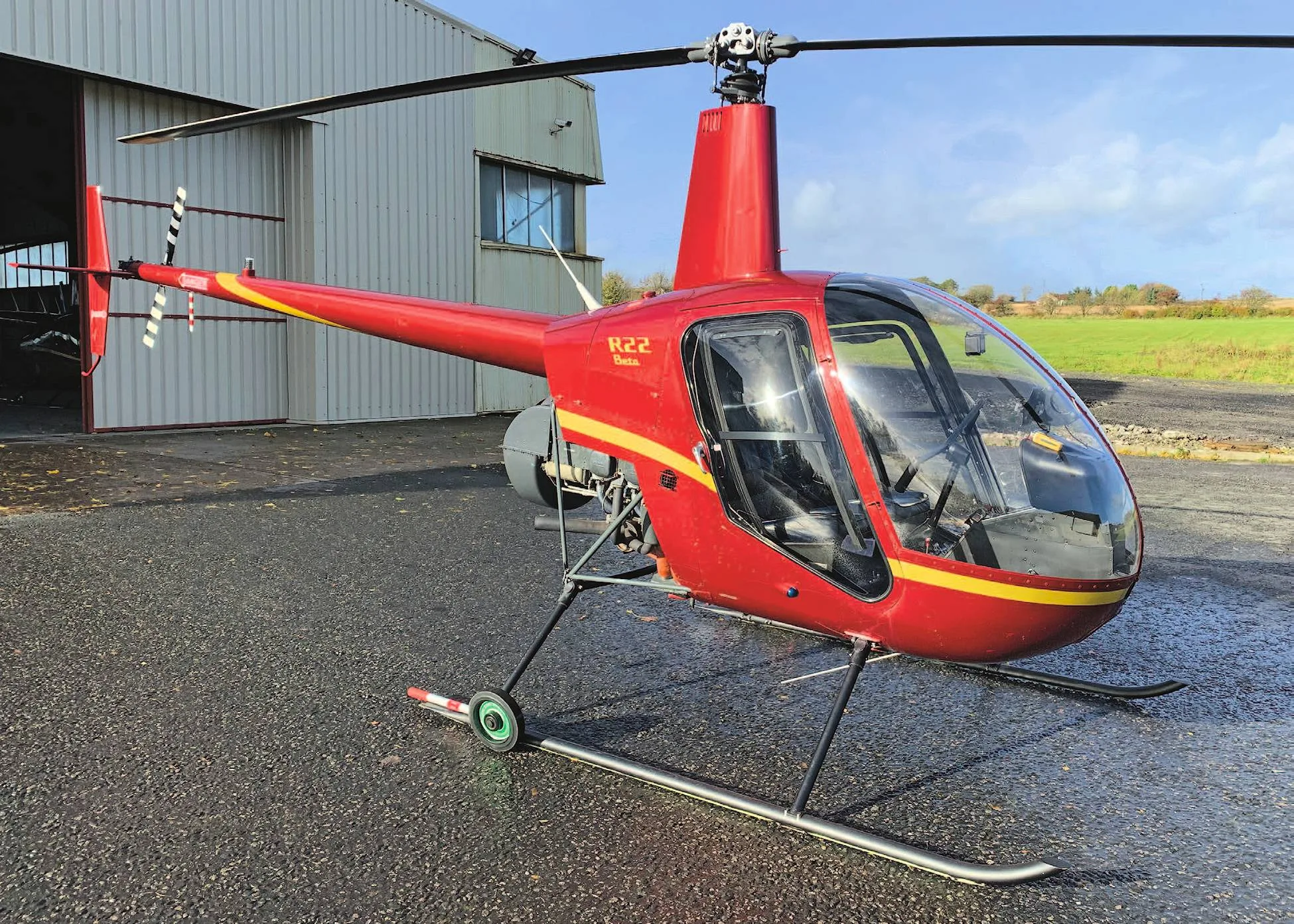
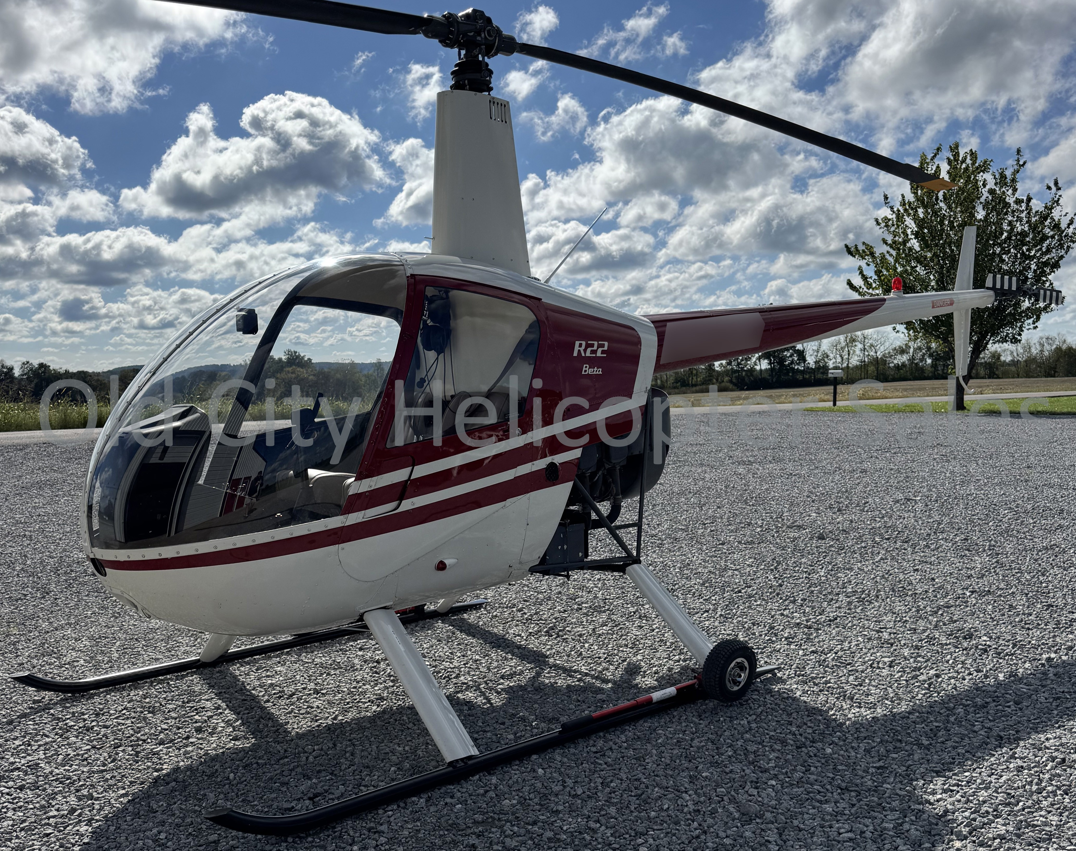
Free — save the R22 BETA to your watchlist and track it in one place.
More Robinson R22 Betamanuals & documents
See all 14 →- AAIB Bulletin: 10/2019Other Documents
- AAIB Bulletin: 4/2018Other Documents
- R22 Spare Parts Price ListChecklist
- ROBINSON R22 SERIES SECTION 6 WEIGHT AND BALANCEWeight And Balance
- R22 Spare Parts Price ListParts Catalog
- ATSB Transport Safety ReportOther Documents
- ROBINSON MODEL R22Specifications
- SAFETY STUDY OF WIRE STRIKE DEVICES INSTALLED ON CIVIL AND MILITARY HELICOPTERSOther Documents
- AAIB Bulletin: 3/2007Other Documents
- AAIB Bulletin No: 3/99 Ref: EW/G98/11/16Other Documents
- AAIB Bulletin No: 10/99Service Bulletins
- AAIB Bulletin No: 10/98Service Bulletins
If you fly the Robinson R22 Beta, you may also be researching these.
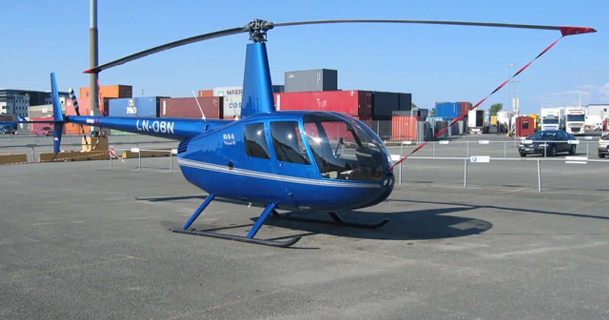
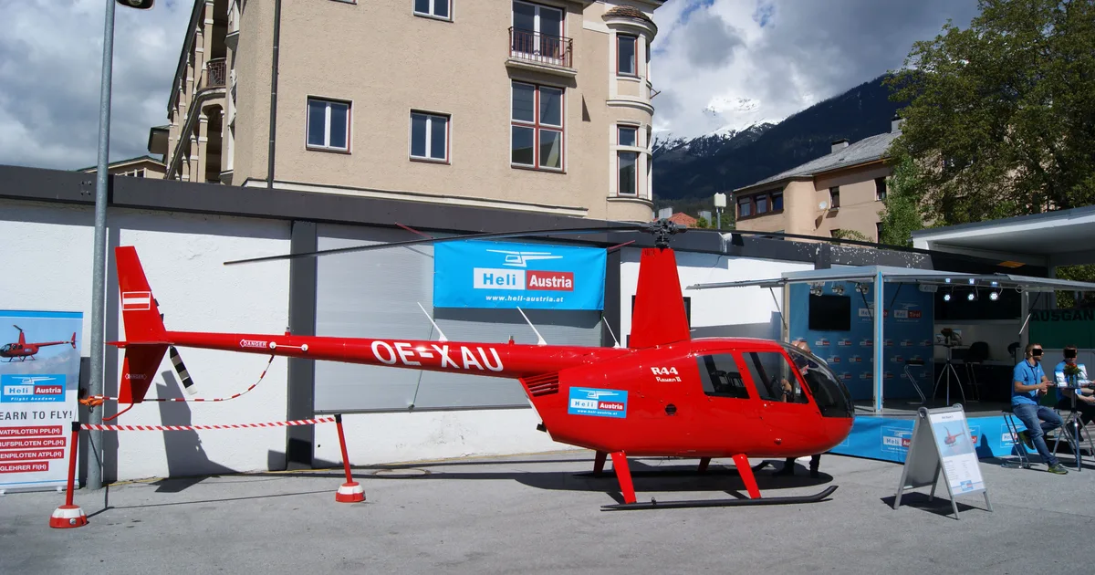

In this document
System Description
The SunSpot 36 and 46 landing and taxi lights are LED replacements for existing PAR36 and PAR46 configurations. They provide a wide beam pattern with increased intensity and color rendering. The standard configuration is a two-terminal light, with some models featuring an integrated Pulse/WigWag mode for enhanced visibility.
Model Numbers
The document lists various models of SunSpot lights, including the SunSpot 36LX, 36HX, and 46 series, detailing their part numbers, voltage requirements, current draw, power output, and weight. For example, the SunSpot 36LX has a voltage range of 9-40V and draws 3.2A at 14V.
Installation Procedures
Installation procedures include disconnecting aircraft power, ensuring all switches are off, and using approved mounting hardware. The document emphasizes that the SunSpot lights are drop-in replacements for existing bulbs and outlines the necessary steps to ensure proper installation, including wiring connections and alignment.
Airworthiness Limitations
The Airworthiness Limitations section specifies required inspections and maintenance under FAA regulations. It includes a schedule for functional checks and inspections at 50-hour and 100-hour intervals, as well as annual checks.
Wiring Diagrams
Wiring diagrams are provided for various configurations of the SunSpot lights, including single and dual installations with and without pulse functions. These diagrams are crucial for ensuring correct electrical connections and functionality.
Safety notes
- Ensure proper grounding to prevent electrical issues.
- Verify that the installation does not adversely affect aircraft weight and balance.
- Perform inspections after hard landings or lightning strikes.
Full document text
0027-0001 Part 27 Instructions for Continued Airworthiness including Installation Instructions Rev_A.docx Page 1 of 20 Part 27 Instructions for Continued Airworthiness (ICA) INCLUDING INSTALLATION INSTRUCTIONS SunSpot 36 AND 46 LANDING AND TAXI LIGHTS INSTALLED ON AIRCRAFT LISTED IN APPROVED MODEL LIST, ST-20-502-01-1 AeroLEDs, LLC 8475 W. Elisa St. Boise, ID, 83709 208-850-3294 NOTE: A printed copy of this document may not be the latest revision. It is the responsibility of the user to ensure that the latest revision is used. The latest revision of this document may be printed from the AeroLEDs electronic document repository. Revision history follows on page 2 This document contains proprietary information of AeroLEDs. Neither receipt nor possession thereof confer any right to reproduce or use, or disclose, in whole or in part, any such information without written permission from AeroLEDs. Approval Name Intent Author Ryan Edmark Installation and Operation Instructions for the Sunspot 36 and 46 series lights. Check Nate Calvin Quality Mark McCormack Date: 23 February 2021 Status: Released Typed signatures indicate approval. Handwritten, or electronic signature approval of this document is on file at AeroLEDs, Boise, Idaho. Document Number 0027-0001 Revision A 0027-0001 Part 27 Instructions for Continued Airworthiness including Installation Instructions Rev_A.docx Page 2 of 20 REVISION RECORD Rev Description Date Author IR Initial Revision 12/01/2020 R. Edmark A Updated to include Pulse Function use on lights 02/23/2021 E. Allen Please visit www.aeroleds.com to verify the revision is current. 0027-0001 Part 27 Instructions for Continued Airworthiness including Installation Instructions Rev_A.docx Page 3 of 20 TABLE OF CONTENTS System Description ....................................................................................................................................................... 4 Model Numbers ............................................................................................................................................................. 4 Airworthiness Limitations ............................................................................................................................................ 8 Instructions for Continued Airworthiness .................................................................................................................. 8 Wiring Diagrams .......................................................................................................................................................... 11 Appendix A .......................................................................................................................................................................... 14 0027-0001 Part 27 Instructions for Continued Airworthiness including Installation Instructions Rev_A.docx Page 4 of 20 System Description SunSpot™ 36 and 46 Landing and Taxi lights are designed as LED drop-in replacements for existing PAR36 and PAR46 light configurations. The AeroLEDs SunSpot™ lights are designed to provide a wide beam pattern at an increased intensity with full-scale color rendering. The standard configuration for both SunSpot™ 36 and 46 lights is a two terminal light only. Some models include an integrated Pulse/WigWag mode to significantly increase recognition, versions with that feature include an (H) in the part number. Model Numbers Table 1 Model Part Number Description Voltage (V) Current (Amps) Power (W) Weight* (ounces) SunSpot 36LX 01-1030-L-A Landing 9-40 3.2 @ 14V 45 10.1 SunSpot 36HX 01-1030-H-A Landing w/ Pulse SunSpot 36LX 01-1030-L-B Taxi SunSpot 36HX 01-1030-H-B Taxi w/ Pulse SunSpot 36-4313 01-1030-4313 Landing 14 6.8 @ 14V 95 11.5 01-1030-4313-H Landing w/Pulse SunSpot 36-4314 01-1030-4314 Taxi 01-1030-4314-H Taxi w/Pulse SunSpot 36-4587 01-1030-4587 Taxi 28 3.6 @ 28V 100 01-1030-4587-H Taxi w/Pulse SunSpot 36-4596 01-1030-4596 Landing 01-1030-4596-H Landing w/Pulse SunSpot 46-4522 01-2230-4522 Landing 14 10.2 @ 14V 140 20 SunSpot 46-4554 01-2230-4554 Taxi 28 6.3 @ 28V 175 01-2230-4554-H Taxi w/Pulse SunSpot 46-4580 01-2230-4580 Landing 01-2230-4580-H Landing w/Pulse SunSpot 46-4582 01-2230-4582 Flood * Verify no appreciable affect to weight and balance after installation of LED lights. 0027-0001 Part 27 Instructions for Continued Airworthiness including Installation Instructions Rev_A.docx Page 5 of 20 SunSpot LED Landing and Taxi Light Cross Reference Table 2 Size Voltage Model * Watts Candela Lumens Model Part # Voltage Watts Candela Lumens GE 4509 GE 4595 Q4632 250 75,000 3,750 SunSpot 36-4313 01-1030-4313 14 100 150,000 11,000 H7604 50 50,000 750 GE 4700 100 75,000 1,500 GE 4313 90,000 Q4631 80,000 Q5587 40,000 3,750 GE 4596 90,000 3,750 GE 5596 3,750 Q5596 3,750 14 GE 4522 250 290,000 3,750 SunSpot 46-4522 01-2230-4522 14 140 180,000 15,400 GE 4553 250 300,000 3,750 GE 4566 150,000 GE 4580 400,000 GE 4581 400,000 Q4681 310,000 Q4566 150,000 INCANDESCENT LANDING LIGHT BULBS AeroLEDs FAA PMA CERTIFIED LANDING LIGHTS PAR36 14 100 60,000 1,500 SunSpot 36 01-1030-L-A 9-36V 45 65,000 4,950 SunSpot 36 01-1030-L-A 9-36V 45 65,000 4,950 150,000 11,000 28 250 SunSpot 36-4596 01-1030-4596 28 100 150,000 11,000 250 3,750 SunSpot 36-4313 01-1030-4313 14 100 150,000 28 SunSpot 46-4580 01-2230-4580 175 PAR46 250,000 19,250 450 6,750 28 Note: 1. The Incandescent model numbers listed in the table above represent the most common PAR36 and PAR46 landing lights installed on Part 27 aircraft. The SunSpot 36 and 46 lights may be substituted for other incandescent or halogen lamp part numbers by selecting the appropriate size, function, and voltage from the table.
Show full textShow less
2. All AeroLEDs part numbers listed in the above table may be substituted with the pulse version of the light except SunSpot 46-4522 (See Table 1) 0027-0001 Part 27 Instructions for Continued Airworthiness including Installation Instructions Rev_A.docx Page 6 of 20 Table 3 Note: 1. The Incandescent model numbers listed in the table above represent the most common PAR36 and PAR46 taxi lights installed on Part 27 aircraft. The SunSpot 36 and 46 lights may be substituted for other incandescent or halogen lamp part numbers by selecting the appropriate size, function, and voltage from the table. 2. All AeroLEDs part numbers listed in the above table may be substituted with the pulse version of the light (See Table 1) Size Voltage Model * Watts Candela Lumens Model Part # Voltage Watts Candela Lumens 14 GE 4503 40 11,000 640 GE 4502 10,000 GE 4505 45,000 GE 4589 5,000 GE 4593 1,500 GE 4591 GE Q4591 GE 4594 GE 4587 250 40,000 4,000 GE 4626 150 30,000 2,400 GE 4627 100 3,000 1,600 GE Q5587 250 40,000 6,750 GE 4570 32,000 GE 4571 7,000 GE 4572 4,500 GE 4551 75,000 GE Q4551 60,000 Q454 90,000 GE Q5554 70,000 GE 4582 20,000 6,750 SunSpot 46-4582 01-2230-4582 23,000 19,000 175 100,000 19,250 100 50,000 11,000 PAR46 28 150 2,400 SunSpot 46-4554 100 SunSpot 36-4587 250 4,000 450 7,200 20,000 1,500 28 01-1030-4587 01-2230-4554 28 INCANDESCENT TAXI LIGHT BULBS AeroLEDs FAA PMA CERTIFIED TAXI/FLOOD LIGHTS PAR36 SunSpot 36 01-1030-L-B 9-36V 45 15,000 4,950 28 50 800 0027-0001 Part 27 Instructions for Continued Airworthiness including Installation Instructions Rev_A.docx Page 7 of 20 Modes of operation (pulse models only) Table 4 Current consumption per input Table 5 Model Part Number Modes Inputs PWR 14VDC* GND YLW BLU GRN SunSpot 36LX 01-1030-L-A Landing Only 3.2A 3.2A NA SunSpot 36HX 01-1030-H-A Landing Mode 3.2A NA ≤10mA Pulse Mode NA 3.2A SunSpot 36LX 01-1030-L-B Taxi Only 3.2A NA SunSpot 36HX 01-1030-H-B Taxi Mode 3.2A NA ≤10mA Pulse Mode NA 3.2A SunSpot 36-4313 01-1030-4313 Landing Only 6.8A 6.8A NA 01-1030-4313-H Landing Mode 6.8A NA ≤10mA Pulse Mode NA 6.8A SunSpot 36-4314 01-1030-4314 Taxi Only 6.8A NA 01-1030-4314-H Landing Mode 6.8A NA ≤10mA Pulse Mode NA 6.8A 28VDC* SunSpot 36-4587 01-1030-4587 Taxi Only 3.6A 3.6A NA 01-1030-4587-H Landing Mode 3.6A NA ≤10mA Pulse Mode NA 3.6A SunSpot 36-4596 01-1030-4596 Landing Only 3.6A NA 01-1030-4596-H Landing Mode 3.6A NA ≤10mA Pulse Mode NA 3.6A SunSpot 46-4522 01-2230-4522 Landing Only 10.2A 10.2A NA SunSpot 46-4554 01-2230-4554 Taxi Only 6.3A 6.3A NA 01-2230-4554-H Landing Mode 6.3A NA ≤10mA Pulse Mode NA 6.3A SunSpot 46-4580 01-2230-4580 Taxi Only 6.3A NA 01-2230-4580-H Landing Mode 6.3A NA ≤10mA Pulse Mode NA 6.3A SunSpot 46-4582 01-2230-4582 Flood Only 6.3A NA *Nominal Mode Switch Position Mode Switch Position Function Pulse Open Landing Open Light OFF Open Closed Landing Closed Open Pulse Closed Closed Pulse Note: Refer to §5 Wiring Diagrams 0027-0001 Part 27 Instructions for Continued Airworthiness including Installation Instructions Rev_A.docx Page 8 of 20 Airworthiness Limitations The Airworthiness Limitations Section is FAA approved and specifies inspections and other maintenance required under 14 CFR §§ 43.16 and 91.403 of the Federal Aviation Regulations unless an alternative program has been FAA approved. Instructions for Continued Airworthiness Sunspot series LED landing or taxi light assembly contains no user serviceable items. Should any LED fail, unit must be replaced. Table 6 Interval Description 50 hr*. • Perform functional check on light(s) • Replace components as required 100 hr. • Perform functional check on light(s) • Inspect for discoloration of lens • Inspect mounting for security • Inspect all connectors for good engagement • Inspect wiring for chaffing / defects • Replace components as required Annually --SAME AS 100 HOUR-- *In the event of a hard landing or lightning strike perform 50hr inspection to ensure no damage has occurred to the LED light. Installation Consult AC 43.13-1B Ch 11 for guidance on acceptable methods, techniques, and practices. Mount in approved bulb holder. For retrofit installation existing circuit breaker or fuse may typically be used. Procedures contained herein are not intended to conflict with procedures set forth by aircraft OEM, nor do they supersede FAA approved manuals and FAA regulations. Installation Procedures Reference the airframe manufacturer’s maintenance manual to complete the following steps Note: SunSpot 36 and 46 lights included in this STC are drop-in replacements for PAR36 and PAR46 legacy bulbs. If the AeroLEDs light(s) chosen for installation are a different wattage than the light(s) being removed, ensure the Electrical Load is not appreciably affected and ensure that all circuit components (circuit breaker, wire, switches, relays, etc., as applicable) are appropriate for the light(s) being installed. a. Prepare aircraft for maintenance: b. Disconnect aircraft power and ground c. Ensure all switches are in the OFF position d. Attach maintenance warning tags e. Pull landing/taxi light circuit breakers f. Remove light covers to gain access to lamp assembly(s) and bracket(s) g. Remove existing lamp(s) from brackets, mark and retain hardware 0027-0001 Part 27 Instructions for Continued Airworthiness including Installation Instructions Rev_A.docx Page 9 of 20 h. Record weight of removed lamps This installation procedure is for single or multiple light installations. Wiring diagrams are provided for single, dual, and quad light installations. For lights without pulse, existing aircraft wiring, switches and breakers may be utilized. Versions with Pulse: Pulse function is a self-contained feature and does not require use of external control circuitry. If you are adding a pulse light to an aircraft that does not have a pulse function (i.e. a pulse box), the installer would need to run the appropriate wiring and add the appropriate switch to enable this function. This STC approves adding this function only if the following criteria is met: • The wiring used must be contained in the table of acceptable wires found in FAA Advisory Circular 43.13-1B, Section 7 (Table of Acceptable Wires), pages 11-39 through 11-41. • The switch used must be an aviation switch added to a switch panel or console. The switch must contain a placard that identifies the operation of that switch as a “pulse operation” for the light. This STC does NOT allow the replacement of the switch on any flight controls. Reference FAA Advisory Circular 43.13-1B, Chapter 11, Section 4, Paragraph 11-53 (page 11-16). • Any other items used must be aviation grade items that are standard for adding avionics and/or other aircraft features. • Follow guidance in FAA Advisory Circular 43.13-1B, Chapter 11 for installation to include but not limited to wire routing, bundling, clamping, and separation. Refer to aircraft manufacturer’s service manual and/or illustrated parts catalog to identify landing and/or taxi light system installed in your aircraft. This will provide information on location of components and assembly details Mount LED light with a minimum 4-inch clearance to exhaust system components unless adequate heat shielding is utilized to block radiant heat. Reference airframe manufacturer’s current maintenance manual and install LED light(s) in brackets using retained hardware Ensure alignment key is fitted to bracket Install suitable aircraft approved connecters or splices to connect landing light assemblies to wires routed from switch in accordance with wiring diagram(s). Screw terminals are not polarity sensitive a. Yellow wire is used to power pulse mode (see Table 5) b. Blue and green wires are low current signals for synchronization in two and four light installations (see Table 5) c. Install an appropriate aircraft approved switch and circuit breaker of correct rating for lights installed for pulse function. Original landing light switch/switches may be used. Placard switches appropriately. Verify proper operation of LED light(s), in both pulsing and steady functions (as appropriate to installation) Using appropriate aircraft maintenance manual, verify light angle has not changed, and is oriented & aimed in accordance with manufacturer’s instructions Reinstall associated light hardware IAW aircraft maintenance manual Perform an operational check of the light(s) to determine that the installed light(s): a. Generate no objectionable glare to the pilot b. Do not adversely affect the pilot by halation c. Provide enough light for night operations, including hovering and landing d. Will not adversely affect any installed systems or equipment with EMI/RFI interference 0027-0001 Part 27 Instructions for Continued Airworthiness including Installation Instructions Rev_A.docx Page 10 of 20 Record installation with appropriate logbook entry Note: The use of shielded cable is recommended although not required for installation. It is recommended that ground connections for all lights be made at a single location on aircraft central ground bus. This “single point ground” scheme helps to eliminate ground loops and ground bounce that can occur when using airframe as a ground. Removal Procedures Reference the airframe manufacturer’s maintenance manual to complete the following steps Note: SunSpot 36 and 46 lights included in this STC are drop-in replacements for PAR36 and PAR46 legacy bulbs. Follow the below steps to remove the AeroLEDs light(s). The aircraft maintenance manual also identifies the landing and/or taxi light removal procedure(s). This procedure is the same for either the OEM light(s) or the AeroLEDs light(s). a. Prepare aircraft for maintenance: b. Disconnect aircraft power and ground c. Ensure all switches are in the OFF position d. Attach maintenance warning tags e. Pull landing/taxi light circuit breakers f. Remove light covers to gain access to lamp assembly(s) and bracket(s) g. Remove lamp(s) from brackets, mark and retain hardware h. Disconnect wiring connections This removal procedure is for single or multiple light installations i. To reinstall the landing/taxi light(s), please refer to section 4.2 of this document Record removal with appropriate logbook entry Troubleshooting If light is not functioning properly, not fully powering up, or not staying powered on, try the following steps to correct problem: a. Check for proper voltage at power input wire to light b. Ensure light is adequately grounded c. Check for continuity in wiring and connections d. If wiring is verified, remove light and bench-check with appropriately sized power supply If above actions do not correct problem, contact AeroLEDs tech support at 1-208-850-3294 for a resolution. 0027-0001 Part 27 Instructions for Continued Airworthiness including Installation Instructions Rev_A.docx Page 11 of 20 Wiring Diagrams Wiring Diagram for Single SunSpot Landing, Taxi, or Flood Light without Pulse Figure 5-1 Wiring Diagram for Single Sunspot Landing or Taxi Light with Pulse Figure 5-2 Note: Landing Switch for reference only 0027-0001 Part 27 Instructions for Continued Airworthiness including Installation Instructions Rev_A.docx Page 12 of 20 Wiring Diagram for Dual SunSpot Landing or Taxi Lights with Pulse (WigWag) Figure 5-3 Note: Landing Switch for reference only If lights are installed in close proximity (within two feet), it is recommended to install using an AeroLEDs sync circuit. • AeroLEDs part number 00-8120 • Installation Guide 0017-0002 0027-0001 Part 27 Instructions for Continued Airworthiness including Installation Instructions Rev_A.docx Page 13 of 20 Wiring Diagram for Four LED SunSpot Landing or Taxi Lights with Pulse (WigWag) Figure 5-4 0027-0001 Part 27 Instructions for Continued Airworthiness including Installation Instructions Rev_A.docx Page 14 of 20 Appendix A AeroLEDs SunSpot 36 and 46 LED lights contained in this document are approved for installation on the following makes and models listed on AML- ST-20-502-01-1 Table 7 Item # Make Model TCDS Cert. Basis MDL ICA Notes Initial Approval Date Amended Date 1 Aero Resources, Inc. J-2 H6WE 14 CFR Part 27 / 27-0 ST-20-502-02 N/A 1 TBD N/A 2 Air & Space America, Inc. 18A 1H17 CAR 6 / 6-4 ST-20-502-02 N/A 1 TBD N/A 3 Airbus Helicopters Deutschland GmbH BO-105A BO-105C BO-105S BO-105LS A-1 BO-105LS A-3 H3EU 14 CFR FAR 21.29 and Part 27 / 27-14 ST-20-502-02 N/A 1 TBD N/A 4 Airbus Helicopters Deutschland GmbH EC135P1 EC135P2 EC135P2+ EC135T1 EC135T2 EC135T2+ H88EU 14 CFR FAR 21.29 and Part 27 / 27-31 ST-20-502-02 N/A 1 TBD N/A 5 Airbus Helicopters France AS350C AS350D AS350D1 AS350B AS350B1 AS350B2 AS350BA AS350B3 EC130 B4 EC130 T2 H9EU 14 CFR FAR 21.29 and Part 27 / 27-40 ST-20-502-02 N/A 1 TBD N/A 6 Airbus Helicopters France EC120B R0001RD 14 CFR FAR 21.29 and Part 27 / 27-33 ST-20-502-02 N/A 1 TBD N/A 7 Airbus Helicopters France SA341G SA342J H6EU 14 CFR FAR 21.29 and Part 27 / 27-4 ST-20-502-02 N/A 1 TBD N/A 8 Airbus Helicopters France SE.3160 Alouette II SA.316B Alouette III SA.315B Alouette III SA.319B Alouette III SA.316C Alouette III H1IN CAR 10 (FAR 21.29) CAR 6 / 6-4 ST-20-502-02 N/A 1 TBD N/A 0027-0001 Part 27 Instructions for Continued Airworthiness including Installation Instructions Rev_A.docx Page 15 of 20 Item # Make Model TCDS Cert. Basis MDL ICA Notes Initial Approval Date Amended Date 9 Airbus Helicopters France AS355E AS355F AS355F1 AS355F2 AS355N AS355NP H11EU 14 CFR FAR 21.29 and Part 27 / 27-21 ST-20-502-02 N/A 1 TBD N/A 10 Airbus Helicopters France SE 3130-Aloutte II SE 313B-Aloutte II SA 3180-Aloutte Astazou SA 318B-Aloutte Astazou SA 318C-Aloutte Astazou 7H1 CAR 10, CAR 6 / 6-8 ST-20-502-02 N/A 1 TBD N/A 11 Bell Helicopter Textron Canada Limited 206 206A 206A-1 (OH-58A) 206B 206L 206L-1 206L-3 206L-4 407 H2SW 14 CFR FAR 21.29, CAR 6 / 6-5, and 14 CFR Part 27 / 27-28 ST-20-502-02 N/A 1 TBD N/A 12 Bell Helicopter Textron Canada Limited 427 R00001RC 14 CFR Part 27 / 27-31 ST-20-502-02 N/A 1 TBD N/A 13 Bell Helicopter Textron Canada Limited 429 R00003RD 14 CFR Part 27 / 27-44 ST-20-502-02 N/A 1 TBD N/A 14 Berlin Doman Helicopters, Inc. LZ-5 1H10 CAR 6 ST-20-502-02 N/A 1 TBD N/A 15 Brantly International, Inc. B-2 (YHO 3BR) B-2A B-2B 2H2 CAR 6 / 6-2 ST-20-502-02 N/A 1 TBD N/A 16 Charles D. Linza Navy HUP-3 H4WE 14 CFR FAR 21.25 ST-20-502-02 N/A 1 TBD N/A 17 Consolidated Air Crane, Inc. CH34A CH34C HSS-1/UH-34D HSS-2N/UN-34J H8SW 14 CFR FAR 21.25 ST-20-502-02 N/A 1 TBD N/A 18 Continental Copters, Inc. U. S. Army OH-13H H5SW 14 CFR FAR 21.25 / 21- 36, CAR 6 / 6-0 ST-20-502-02 N/A 1 TBD N/A 19 Costruzioni Aeronautiche Giovanni Agusta S.p.a. AB-102 7H3 CAR 10 ST-20-502-02 N/A 1 TBD N/A 0027-0001 Part 27 Instructions for Continued Airworthiness including Installation Instructions Rev_A.docx Page 16 of 20 Item # Make Model TCDS Cert. Basis MDL ICA Notes Initial Approval Date Amended Date 20 FH1100 Manufacturing Corporation 1100 (OH-5A) FH-1100 H2WE CAR 6 / 6-4 ST-20-502-02 N/A 1 TBD N/A 21 Scott’s – Bell 47, Inc. U. S. Army OH-13H U. S. Army OH-13E H7SW 14 CFR FAR 21.25 / 21- 0, CAR 6 / 6-0 ST-20-502-02 N/A 1 TBD N/A 22 Helicopter Technik Munchen GmbH & Co. Anlagen KG FJ Sky-Trac H5EU 14 CFR Part 27 / 27-4 ST-20-502-02 N/A 1 TBD N/A 23 Siam Hiller Holdings, Inc. UH-12B (Navy THE-2, Army H23B) UH-12C 6H2 CAR 6 / 6-0 ST-20-502-02 N/A 1 TBD N/A 24 Siam Hiller Holdings, Inc. UH-12L UH-12L4 H1WE CAR 6 / 6-4 ST-20-502-02 N/A 1 TBD N/A 25 Siam Hiller Holdings, Inc. UH-12 UH-12A (Navy HTE-1, Army H23A) 6H1 CAR 6 / 6-0 ST-20-502-02 N/A 1 TBD N/A 26 Siam Hiller Holdings, Inc. UH-12D (Army UH- 23D) 4H10 CAR 6 / 6-6 ST-20-502-02 N/A 1 TBD N/A 27 Invest In Opportunities, Inc. HUS-1 H9WE 14 CFR FAR 21.25 ST-20-502-02 N/A 1 TBD N/A 28 Kaman Aerospace Corporation K-1200 TR7BO 14 CFR Part 27 / 27-37 ST-20-502-02 N/A 1 TBD N/A 29 Leonardo S.p.A. A109 A109A A109A II A109C A109K2 A109E A109S A119 AW119 MKII AW109SP H7EU 14 CFR FAR 21.29 and Part 27 / 27-42 ST-20-502-02 N/A 1 TBD N/A 30 Lockheed-California Company L-286 H5WE CAR 6 / 6-7 ST-20-502-02 N/A 1 TBD N/A 31 McCulloch Motors Corporation MC-4C (USAF YH-30) 6H3 CAR 6 / 6-0 ST-20-502-02 N/A 1 TBD N/A 0027-0001 Part 27 Instructions for Continued Airworthiness including Installation Instructions Rev_A.docx Page 17 of 20 Item # Make Model TCDS Cert. Basis MDL ICA Notes Initial Approval Date Amended Date 32 MD Helicopters Inc. (MDHI) 369 (Army YOH-6A) 369A (Army OH-6A) 369D 369H 369HE 369HM 369HS 369E 500N (not NOTAR) H3WE CAR 6 / 6-4 ST-20-502-02 N/A 1 TBD N/A 33 MD Helicopters Inc. (MDHI) 369F (Glass Cockpit) 369FF (Glass Cockpit) 600N (Glass Cockpit) H3WE CAR 6 / 6-4 Part 27 / 27-47 ST-20-502-02 N/A 1 TBD N/A 34 MD Helicopters Inc. (MDHI) 500N (NOTAR) H3WE CAR 6 / 6-4 Part 27 / 27-21 ST-20-502-02 N/A 1 TBD N/A 35 MD Helicopters Inc. (MDHI) 600N (non-Glass Cockpit) H3WE Part 27 / 27-30 ST-20-502-02 N/A 1 TBD N/A 36 MD Helicopters Inc. (MDHI) MD900 H19NM 14 Part 27 / 27-26 ST-20-502-02 N/A 1 TBD N/A 37 Omega Aircraft Corporation BS-12D1 1H14 CAR 6 / 6-4 ST-20-502-02 N/A 1 TBD N/A 38 Orlando Helicopter Airways, Inc. HRS-1/CH-19 H-19D H-19A H-19G YH-19A UH-19F UH-19C CH-19E HRS-3/H-19B UH-19D HR1SO 14 CFR FAR 21.25 / 21- 71, CAR 6 / 6-4 ST-20-502-02 N/A 1 TBD N/A 39 Orlando Helicopter Airways, Inc. SH-34J HH-34J UH-34D H-34A H4SO 14 CFR FAR 21.25 / 21- 71, CAR 6 / 6-5 ST-20-502-02 N/A 1 TBD N/A 40 Pacific Aviation Inc. HSS-1/UH-34D HSS-1N/UH-34J CH34A CH34C H15WE 14 CFR FAR 21.25 ST-20-502-02 N/A 1 TBD N/A 41 Robinson Helicopter Company R66 R00015LA 14 CFR Part 27 / 27-44 ST-20-502-02 N/A 1 TBD N/A 42 Robinson Helicopter Company R44 R44 II H11NM 14 CFR Part 27 / 27-24 ST-20-502-02 N/A 1 TBD N/A 0027-0001 Part 27 Instructions for Continued Airworthiness including Installation Instructions Rev_A.docx Page 18 of 20 Item # Make Model TCDS Cert. Basis MDL ICA Notes Initial Approval Date Amended Date 43 Robinson Helicopter Company R22 R22 ALPHA R22 BETA R22 MARINER H10WE 14 CFR Part 27 / 27-10 ST-20-502-02 N/A 1 TBD N/A 44 Scheutzow Helicopter Corporation Model B H1GL 14 CFR Part 27 / 27-9 ST-20-502-02 N/A 1 TBD N/A 45 Scotts-Bell 47 Inc. 47G-2A 47G-5 47G-2A-1 47G-3B-2 47G-3 47G-5A 47G-3B 47G-3B-2A 47G-3B-1 47G-4 47G-4A 2H3 CAR 6 / 6-4 ST-20-502-02 N/A 1 TBD N/A 46 Scotts-Bell 47 Inc. 47 47B 47B3 47D 47D1 47E 47G 47G-2 47H-1 H-1 CAR 6 / 6-0 ST-20-502-02 N/A 1 TBD N/A 47 Scotts-Bell 47 Inc. 47J 47K 47J-2 47J-2A 2H1 CAR 6 / 6-6 ST-20-502-02 N/A 1 TBD N/A 48 Siam Hiller Holdings, Inc. UH-12E UH-12E-L (Army OH-23G) (Army H-23F) 4H11 CAR 6 / 6-3 ST-20-502-02 N/A 1 TBD N/A 49 Sikorsky Aircraft Corporation 269A 269A-1 269B 269C 269C-1 269D 4H12 CAR 6 / 6-8, CAR 8 / 8-0, FAR 21.25 / 21-0 ST-20-502-02 N/A 1 TBD N/A 50 Sikorsky Aircraft Corporation S-51 H-2 CAR 6 / 6-0 ST-20-502-02 N/A 1 TBD N/A 0027-0001 Part 27 Instructions for Continued Airworthiness including Installation Instructions Rev_A.docx Page 19 of 20 Item # Make Model TCDS Cert. Basis MDL ICA Notes Initial Approval Date Amended Date 51 Sikorsky Aircraft Corporation S-52 H-3 CAR 6 / 6-0 ST-20-502-02 N/A 1 TBD N/A 52 Vertical Aviation Technologies, Inc. S-52-2 S-52-3 1H2 CAR 6 / 6-0 ST-20-502-02 N/A 1 TBD N/A 53 Centerpointe Aerospace, Inc. S-55 S-55B S-55C 1H4 CAR 6 / 6-0 ST-20-502-02 N/A 1 TBD N/A 54 Centerpointe Aerospace, Inc. S-58JT S-58A S-58H S-58B S-58J S-58C S-58BT S-58D S-58DT S-58E S-58ET S-58F S-58FT S-58G S-58HT 1H11 CAR 6 / 6-6, Part 29 / 29- 3 (subparts only, see TCDS for full listing) ST-20-502-02 N/A 1 TBD N/A 55 Silvercraft S.co.p.a. SH-4 H2EU 14 CFR Part 27 / 27-1 ST-20-502-02 N/A 1 TBD N/A 56 Sud Aviation SO. 1221 Djinn 7H2 CAR 10, CAR 6 / 6-6 ST-20-502-02 N/A 1 TBD N/A 57 Teryjon Aviation Inc. Fast Kat I (U. S. Army OH-135) H2GL 14 CFR FAR 21.25 ST-20-502-02 N/A 1 TBD N/A 58 The Boeing Company Vertol Division (H21B, H-21C) 42A 42B 44A 44B 1H12 CAR 6 / 6-7 ST-20-502-02 N/A 1 TBD N/A 0027-0001 Part 27 Instructions for Continued Airworthiness including Installation Instructions Rev_A.docx Page 20 of 20 Item # Make Model TCDS Cert. Basis MDL ICA Notes Initial Approval Date Amended Date 59 The Enstrom Helicopter Corporation F-28 F-28A 280 F-28C F-28C-2 F-28C-2R 280C F-28F F-28F-R 280F 280FX TH-28 480 480B H1CE CAR 6 / 6-5, 14 CFR Part 27 / 27-23, FAR 21.25 / 21-0 ST-20-502-02 N/A 1 TBD N/A 60 The Kaman Aircraft Corp. K-240 (Military HTK-1) 1H3 CAR 6 / 6-1 ST-20-502-02 N/A 1 TBD N/A 61 The Kaman Aircraft Corp. K-190A K-225 1H1 CAR 6 / 6-0 ST-20-502-02 N/A 1 TBD N/A
What's in the Robinson R22 Beta TCDS
A Type Certificate Data Sheet (TCDS) is the FAA's record of what an aircraft type was approved as. It is the source of truth for weights, seating, fuel and the rules the design was certified against. Expand any line to see what it means.
374 Robinson R22 Beta parts for sale
See all →
Parts listed for sale by vetted eBay sellers — confirmed on eBay at checkout.