Validation of Digital Systems in Avionics and Flight Control Applications
Robinson R44 Clipper · Other Documents
Overview
This document serves as a comprehensive handbook focused on the validation of digital systems in avionics and flight control applications. It outlines techniques, methodologies, tools, and procedures relevant to the validation and certification processes of digital systems throughout their development and certification lifecycle. The handbook is intended for use by engineers, developers, and regulatory agencies involved in the design, development, and certification of avionics systems. It emphasizes a systems engineering approach to integrate and test software and hardware, while also considering the pilot's workload and the impact of new technologies on flight safety and operational efficiency.
- The handbook emphasizes a systems engineering approach for validating avionics systems.
- It covers the entire system life cycle from development to certification.
- Mission factors such as environmental conditions and operational constraints are critical in validation.
- Crew workload evaluation is essential for ensuring pilot safety and system effectiveness.
- Current validation procedures include design validation, hardware testing, and software verification.
Document
Source
Originally published by apps.dtic.mil. Sprinkle hosts a reference copy with an added summary, specifications and searchable full text.
Document details
- Type
- Other Documents
- Year
- 1983
- Pages
- 472
- File size
- 25 MB
- Publisher
- apps.dtic.mil
Common. Rarer than 5% of the aircraft models we track.
Most owners only have the POH. Here's the essential set for the Robinson R44 Clipper.
- Pilot's Operating Handbook / AFM
- Checklist
- Maintenance Manual
- Parts Catalog (IPC)
- Systems & Wiring
- Service Bulletins
- Type Certificate (TCDS)
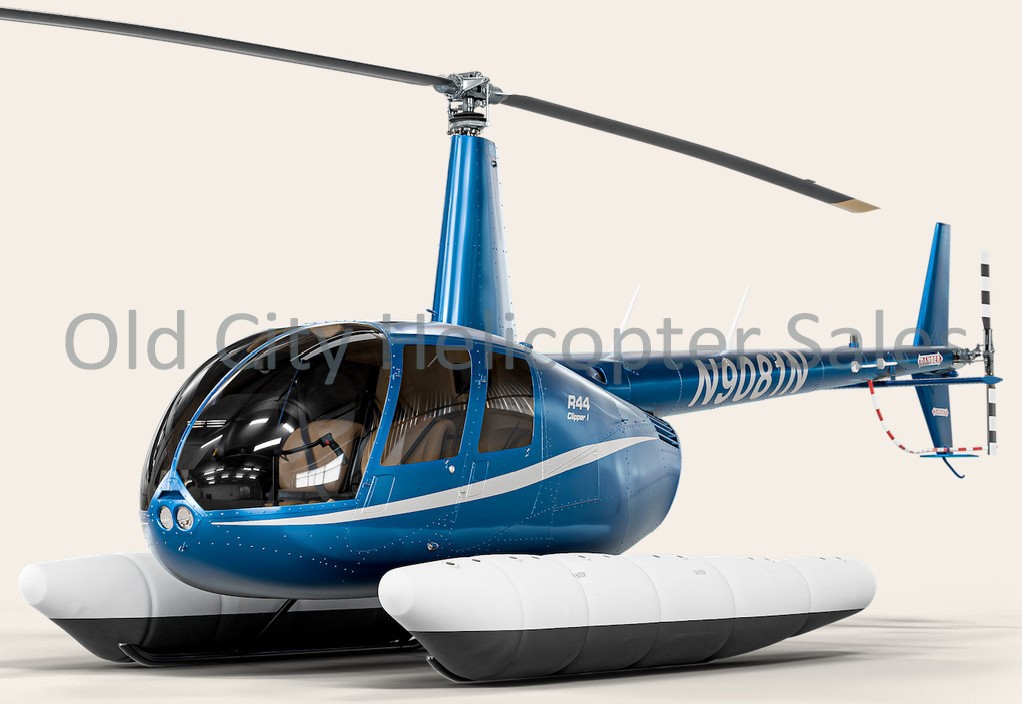
Robinson R44 Clipper for sale now

Free — save the R44 Clipper to your watchlist and track it in one place.
More Robinson R44 Clippermanuals & documents
See all 31 →- R44 Raven II & Clipper II Price ListChecklist
- Performance Data for the Robinson R44 ClipperPerformance
- ROBINSON MAINTENANCE MANUAL R44 SERIESService Bulletins
- R44 Raven I & Clipper I Price ListChecklist
- Performance Data for the Robinson R44 ClipperPerformance
- A Performance Benchmark of Recent Personal Air Vehicle Concepts for Urban Air MobilityOther Documents
- In-flight break-up, Robinson R44 Raven I helicopter, VH-NBYOther Documents
- Drive system failure and forced landing, involving Robinson Helicopter Company R44 Clipper II, VH-SXCOther Documents
- Robinson R44 Clipper ChecklistChecklist
- AAIB Bulletin 7/2021Service Bulletins
- Performance Data for the Robinson R44 ClipperPerformance
- R44 Raven Internal Check-listChecklist
If you fly the Robinson R44 Clipper, you may also be researching these.
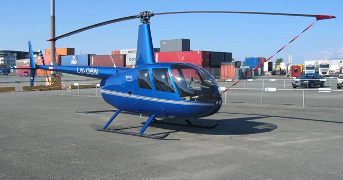
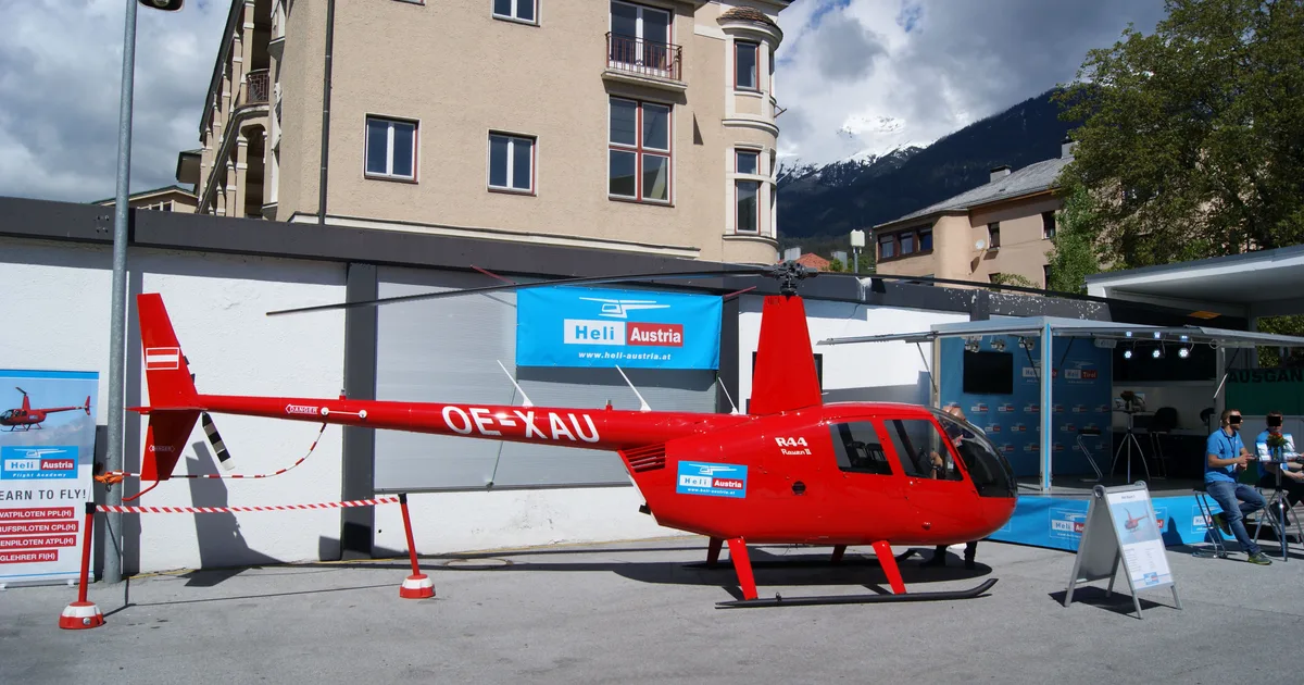

In this document
Introduction
The introduction outlines the purpose of the handbook, which is to provide guidance on the validation of digital systems in avionics. It discusses the importance of ensuring that these systems meet regulatory standards and the need for effective methodologies in their development.
System Life Cycle Overview
This section provides an overview of the system life cycle, detailing the stages from conceptual development through to verification and validation. It emphasizes the criticality of each phase and the importance of thorough testing and evaluation.
Mission Factors
This section discusses various mission factors that can affect the validation process, including environmental conditions, operational constraints, and safety requirements. It highlights the need for robust systems that can operate effectively under varying conditions.
System Architectures
This section explores different system architectures used in avionics, including fault-tolerant designs and advanced integrated systems. It discusses the implications of these architectures on system performance and reliability.
Crew Workload Evaluation
This section addresses the evaluation of crew workload in relation to new avionics systems. It discusses human factors engineering goals and the impact of automation on pilot workload and safety.
Current Validation Procedures
This section outlines the current procedures for validating avionics systems, including design validation, hardware testing, and software verification. It emphasizes the importance of rigorous testing to ensure system reliability.
Recommended Validation Procedures
This section provides recommendations for best practices in the validation of digital systems, including methodologies for system design, integration, and testing.
Glossary
The glossary contains definitions of key terms used throughout the handbook, providing clarity on technical language and concepts related to avionics validation.
Safety notes
- The document stresses the importance of compliance with regulatory standards to ensure safety in avionics systems.
- It highlights the need for thorough testing to identify and mitigate potential faults in digital systems.
Full document text
D-A133 222 VALIDATION OF DIGITAL SYSTEMS IN AVIONICS AND FLIGHT ±4I CONTROL APPLICATIONS..(U) BRTTELLE COLUMBUS LABS OH E F HITT ET AL. JUL 83 DOT/FAA/CT-82/ii5 UNCLASSIFIED DTF83-8i-C-00059 F/G 1/3 N smmomhhhhhil EhEmhmhhhhEmhI smmhhmhmhhEmh smmhhmhhmhhmh Eomhmhhmhhhhl EEmhhhEohhhhEI L500 11111 1AS U2 1111 11.6*. - LA 111_L MICROCOPY RESOLUTION TEST CHART NATIONAL BUREAU OF STANDARDS-1963-A Ii -7. 1vAI133 2O22•O.-FAA"c-82/"15 Handbook-Volume I Validation of Digital Systems in Avionics and Flight Control Applications Ellis F. Hitt Jeff Webb Charles Lucius Michael S. Bridgman * Battelle Columbus Laboratories Columbus, Ohio 43201 Donald Eldredge FAA Technical Center Atlantic City Airport, New Jersey 08405 July 1983 This document is available to the U.S. public through the National Technical Information Service, Springfield, Virginia 22161. ':'i "!: ,_D T IC "_ USperiei TrhsMoTato . OCT 04'-C Lii Ptdfr AvtlIfl Adn~frOWaf kIx Technical Center * Lj.. Atlantic City Airport, N.J. 08405 83 09 26 051 ............ .. ... o I NOTICE This document is disseminated under the sponsorship of the Department of Transportation in the interest of information exchange. The United States Government assumes no liability for the contents or use thereof. The United States Government does not endorse products or manufacturers. Trade or -snuf~cturer's names appear herein solely because they are considered essential to the object of this report. .. A Technical Report Documentation Page 1. Report No. 2. Government Accession No. 3. Recipient's Catalog No. V. OT/FAA/CT-82/115 .-___ _ 4. Title and Subtitle 5. Report r)ate HANDBOOK--VOLUME I, VALIDATION OF DIGITAL SYSTEMS 6. Performing Organization Code IN AVIONICS AND FLIGHT CONTROL APPLICATIONS FAA Technical Center 8. Performing Organization Report No. 7. Authorls) E. Hitt, J. Webb, C. Luicus, M. Bridgman, D. Eldredge DOT/FAA/CT-82/115 9. Performing Organization Name and Address 10. Work Unit No. (TRAIS) Battelle-Columbus Laboratories 505 King Avenue I1. Contract or Grant No. Columbus, Ohio 43201 DTFA03-81-C-00059 13. Type of Report and Period Covered 12. Sponsoring Agency Name and Address U.S. Department of Transportation Draft Report Federal Aviation Administration June 1981 - July 1982 Technical Center 14. Sponsoring Agency Code Atlantic City Airport, NJ 08405 ACT-340 15. Supplementary Notes 16. Abstract The purpose of this handbook is to identify techniques, methodologies, tools, and pro- cedures in a systems context that may be applicable to aspects of the validation and certification of digital systems at specific times in the development and certifica- tion portion of the system life cycle. The application of these techniques in the development of discrete units and/or systems will result in a completion of a product .. or system which is verifiable and can be validated in the context of the existing regulations/orders for the government regulatory agencies. The handbook uses a sys- tems engineering approach to the integration and testing of software and hardware during the design, development, and implementation phases. The handbook also recog- nizes and provides for the evaluation of the pilot's workload and utilization of the , new control/display technologies, especially when crew recognition and intervention may be necessary to cope with/recover from the effects of faults or failures in the digital systems. In summary, the handbook: (1) Identifies and presents the issues related to the design, development, and implementation of software based digital systems; (2) identifies specific approaches applicable to all aspects of the * verification and validation procedures, at specific times in the development and certification portion of the system life cycle, (3) provides the government regula- tory agencies (especially the Federal Aviation Administration (FAA) as well as the industry with a set of tools/procedures, in a systems engineering context which may be of value in the validation/certification process.. 17. Key Words 18. Distribution Statement Validation/Verification, Airborne Systems Digital Systems, Software Reliability, Software Testing, System Evaluation, Digital Flight Control/Avionics, Safety Assessment, Configuration Management, 19. Security Classif. (of this report) 20. Security Classif. (of this page) 21. No. of Pages 22. Price Unclassified Unclassified Form DOT F 1700.7 (8-72) Reproduction of completed page authorized . TABLE OF CONTENTS Acce'vson For Page SECTION 1* FT 1-1 . - j ,, :11- T .; . I. INTRODUCTION . I-" 1.1 Purpose 1-1 1.2 Distribution 1-- 1.3 Background Di 1-2 1.4 Handbook Scope A, 1-7 1.5 Handbook Organization 1-8 1.6 References -' 1-10 Di \ SECTION 2 2-1 2. Applicable Documents 2-1 SECTION 3 3-1 3. SYSTEM LIFE CYCLE (OVERVIEW) 3-1 3.1 Operational Flight Program (OFP) Development 3-3 3.1.1 Conceptual 3-3 3.1.2 Requirements Definition 3-3 3.1.3 Design and Specification 3-6 3.1.4 Coding 3-8 3.1.5 Testing 3-8 3.1.6 Verification, Validation, Certification, and 3-13 Qualification 3.2 Function Criticality 3-17 3.2.1 Criticality Assessment 3-17 3.3 Potential Problem Areas 3-17 3.4 References 3-20 LIST OF ILLUSTRATIONS Figure Page 3-1 System Life Cycle 3-1 3-2 Software Activities/Products Relation to System Life 3-2 Cycle Phases . °- :.'" iii . .7 3-3 Avionics Software Engineering Process 3-4 3-4 Test Management Milestones 3-7 . 3-5 Software Activities/Products Relation to Verification/ 3-15 Validation Activities 3-6 Verification and Validation Activities by Organization 3-16 * Over Software Life Cycle (Ref. 22) LIST OF TABLES • Table Page 3-1 Function Criticality Categories 3-18
Show full textShow less
3-2 Minimum Verification and Validation Activities 3-19 Grouped by Criticality (Ref. 24) SECTION 4 4-1 4. MISSION FACTORS 4-1 4.1 Mission Environment 4-1 4.1.1 Airline Operations 4-1 4.1.2 Airport Configuration 4-4 4.1.3 Air Traffic Mix/Density at Specific Airports 4-4 as a Function of Time-of-Day 4.1.4 Air Traffic Control/Navigation Aids 4-4 4.1.5 Operating Time Considerations in Validation 4-5 4.2 Atmospheric Environment 4-6 4.2.1 Lightning 4-7 4.3 Electromagnetic Interference 4-8 4.4 Safety Requirements 4-8 4.5 Constraints 4-15 4.5.1 Aircraft 4-15 14.5.2 Airport 4-15 4.5.3 Approach/Landing Performance Limits 4-15 4.5.4 Airline Imposed Constraints 4-17 4.6 Advanced Digital Integrated Flight Control and Avionics 4-17 System Functions 4.6.1 Flight Control Background 4-17 4.6.2 Command Generation (Guidance) Background 4-17 iv ,. 4.6.3 State Estimation (Navigation) Background 4-18 4.6.4 Aircraft System Functions 4-19 4.7 References 4-22 LIST OF ILLUSTRATIONS - Figure Page 4-1 Flux Linkages Versus Conductor Position (Reference 12) 4-9 4-2 Conductor Routing (Reference 12) 4-10 4-3 Frequency Considerations 4-10 4-4 Relationship Between Probability and Severity of Effects 4-13 (Reference 29) 4-5 Block Diagram of Navigation, Guidance, and Control 4-20 Outer Loop LIST OF TABLES Table Page 4-1 Equipment Required for IFR Dispatch 4-2 (FAR Parts 25.1303 and 121.303) 4-2 Airborne Equipment Requirements Categories 4-3 (Categories I and II+) 4-3 Primary Radio Navigation Systems 4-5 4-4 Example of Digital Flight Control and Avionics System 4-6 Operating Profile 4-5 Protection from Indirect Electromagnetic Effects 4-8 4-6 EMI Sources and Susceptibility of a Hypothetical Digital 4-11 Avionics Subsystem 4-7 How to Improve EMC of the Subsystem 4-12 4-8 Quantitative Safety Requirements 4-12 - SECTION 5 5-1 5. SYSTEM ARCHITECTURES 5-1 " 5.1 Fault Tolerant Digital Integrated Flight Control and Avionics 5-1 v ', .. ''..' -:'" '-- "h'.:." "''i'i <""i ''"''" :'i':"-"" ':' ;?' '?i':'': "'.i ':; 2"" : " " : "' " " " -- '-4 ... . .. ...- 5.1.1 Redundancy Techniques 5-4 5.1.2 Motivation for Fault Tolerant Integrated Control 5-5 5.2 Advanced Integrated Digital Flight Control and Avionics 5-6 Systems 5.2.1 Digital Data Buses 5-7 5.3 Software 5-11 5.3.1 Coordinate Systems 5-11 5.3.2 Integrated Control Core Software Modules 5-14 5.4 System Monitoring and Error Management 5-14 . 5.4.1 Processor Failure Detection 5-14 5.4.2 Data Transmission Error Detection 5-16 5.4.3 Data Validity 5-17 5.5 Systems Configuration 5-18 5.5.1 Simplex Configuration 5-19 5.5.2 Single-String Configurations 5-19 5.5.3 Dual System Configuration 5-20 5.5.4 Dual-Dual System Configuration 5-23 5.5.5 Triplex 5-25 5.6 ARINC Subsystems 5-27 5.6.1 Area Navigation System 5-27 5.6.2 Flight Control Computer System 5-31 5.6.3 Flight Management Computer System 5-39 5.6.4 Thrust Control Computer System 5-39 5.6.5 Inertial Reference System (IRS) 5-45 5.6.6 Attitude and Heading Reference System 5-45 5.6.7 Air Data System 5-51 5.6.8 Radio Altimeter 5-51 5.6.9 Airborne Weather Radar 5-51 5.6.10 Airborne Distance Measuring Equipment 5-55 5.6.11 ILS Receiver 5-55 5.6.12 Airborne VOR Receiver 5-56 5.6.13 Airborne ADF System 5-56 5.6.14 Mark 2 Omega Navigation System 5-56 5.6.15 Airborne VHF Communication Transceiver 5-56 5.6.16 Flight Data Acquisition and Recording System 5-57 5.6.17 Mark 3 Air Traffic Control Transponder 5-57 4i (ATCRBS/DABS) 5.6.18 Digital Frequency/Function Selection for Airborne 5-57 Electronic Equipment 5.6.19 Ground Proximity Warning System 5-57 5.6.20 Electronic Flight Instruments (EFI) 5-59 5.6.21 Flight Warning Computer System 5-60 5.6.22 Airborne MLS Receiver 5-60 5.6.23 Analog and Discrete Data Converter System 5-60 vi . . .- 5.6.24 Airborne Separation Assurance System 5-60 5.6.25 Electric Chronometer 5-61 5.6.26 Digital Engine Controller 5-61 5.6.27 Electric Power Generation System 5-61 5.6.28 Synopsis of Digital Interfaces of ARINC 5-62 Characteristic Subsystems 5.7 References 5-67 LIST OF ILLUSTRATIONS Figure Page 5-1 Fault Tolerance Definitional Relationships 5-2 5-2 Fault Types 5-2 5-3 ARINC 429 General Word Format 5-7 5-4 MIL-STD-1553B Word Format 5-10 5-5 MIL-STD-1553B Information Transfer Formats 5-10 5-6 Inertial Coordinate System 5-12 5-7 Earth Fixed Coordinate System 5-12 5-8 Body Axes Coordinate System 5-13 5-9 Locally Level Coordinate System 5-13 • 5-10 Horizontal Plane Coordinate System 5-15 5-11 Flight Management Computer System Configuration 2: 5-20 Single System/Dual CDU Installation 5-12 Flight Management Computer System Configuration 3: 5-21 Dual System Installation 5-13 Dual Digital Flight Control System With Inter-Unit 5-22 Switching (Ref. 39) *' 5-14 Typical Dual-Dual AFS Configuration 5-24 5-15 Typical Triplex DAFS Architecture 5-26 5-16 ARINC 701 Interfaces 5-32 - 5-17 Flight Management Computer System Interface With Flight 5-40 Control System and Other Subsystems " 5-18 ARINC 703 Thrust Control Computer Interface 5-44 vii !." " ,-;. +" .. . . '. - ._ '. - - " ." .. ."• •" . .- - - ." . .. . ." .• .. - - * ' -* S - 5 ** . . . . . . ... . - -S *- - 2 5-19 704 Block Diagram 5-49 LIST OF TABLES Table Page 5-1 Dits Buses 5-8 5-2 ARINC Characteristic 581 Functions 5-28 5-3 ARINC 581 System Inputs - Range and Resolution 5-28 5-4 ARINC Characteristic 581 System Operation With Failed Sensors 5-29 5-5 ARINC Characteristic 583 Basic Functions 5-30 5-6 ARINC 583 System Inputs Range and Resolution 5-30 - 5-7 Example of ARINC Characteristic 583 System Operation With 5-31 Failed Sensors 5-8 ARNIC 701 Flight Control Computer (FCC) System Controller 5-36 Functions 5-9 FCCS Data Words 5-37 5-10 FCCS Discrete Input and Output Word Formats (Discrete 5-37 Word #1) 5-11 FCCS Discrete Word #2 5-38 5-12 ARINC 702 Flight Management System Functions 5-41 5-13 Thrust Control Computer System Components and Functions 5-43 5-14 IRS Digital Summary - Inputs/Outputs (Reference 51) 5-45 5-15 Digital Control Word Format IRS Discrete Word Format 5-47 5-16 AHRS Digital Output Summary 5-50 5-17 Air Data System Digital Data Output Standards 5-52 (Reference 53) 5-18 ADS Discrete Word #1 Format (Reference 53) 5-53 5-19 ADS Discrete Word #2 Format (Reference 53) 5-54 5-20 709 DME Mode Selection Matrix 5-55 5-21 Discrete Work Format (Reference 66) 5-58 5-22 ARINC 725-1 Signal Generator Digital Inputs (Reference 67) 5-59 viii * * -'1 5-23 ARINC 726-1 Flight Warning Computer System Digital Inputs 5-60 (Reference 68) 5-24 ARINC 730-3 Airborne Separation Assurance System Digital 5-61 Inputs (Reference 71) 5-25 Synopsis of Digital Interfaces of ARINC Characteristic 5-63 Subsystems SECTION 6 6-1 6. CREW WORKLOAD EVALUATION 6-1 6.1 Human Factors Engineering Goals 6-I 6.1.1 Safety and Crew Acceptability 6-1 6.1.2 Current Revolutionary Changes in Crew Interface 6-2 6.1.3 Greater Future Design Commonality 6-3 6.2 Regulatory Requirements 6-3 6.2.1 Minimum Crew Determination 6-3 6.2.2 Overall Flight-Deck Evaluation 6-5 6.3 Current Workload Measurement Techniques 6-7 6.3.1 Subjective Measures 6-7Mesue 6.3.2 Performance Measures 6-7 ~6.3.3 Physiological and Biological Measures 6-8 - 6.4 Automation and System Effectiveness 6-9 ..- 6.4.1 Impact on the Pilot 6-10 6.4.2 System Effectiveness 6-12 . •" 6.4.3 Changed Pilot Roles 6-14 6.4.4 Human Needs and Satisfactions 6-16 6.5 Future Workload Measurement Problems 6-17 6.5.1 Evaluation of Stress 6-17 6.5.2 Sources of Pilot Error 6-19 6.5.3 Definitions of Good Design 6-20 6.5.4 Relation of Workload to Safety 6-21 6.6 Recent Certification Programs Overview 6-23 6.6.1 Systems Analysis 6-23 6.6.2 Synthetic Performance Measures 6-25 6.6.3 Flight Test 6-29 6.6.4 Remaining Problems 6-35 6.6.5 Need to Expand the Variety of Procedure 6-35 6.6.6 Classification of Workload Assessment Methods 6-38 6.7 Recommended Applicatio 6-42 ix ................................... 6.7.1 Specific Procedures 6-42 6.7.2 Combined Methods 6-45 6.8 References 6-47 APPENDIX LIST OF ILLUSTRATIONS Figure Page 6-1 Representative Elements in Goal-Effective System Operation 6-13 6-2 The Pilot-Aircraft-Environment Information Flow 6-18 I 6-3 Relation of High and Low Pilot Workload and Safety 6-22 6-4 DC-9-80 Comparison of Equipment Interface Workload with 6-28 DC-9-50 When Autothrottles are Inoperative 6-5 Varieties of Digit Entry Devices 6-36 6-6 Inventory of Available Workload Methods and Issue/Application 6-43 Situations * 6-7 Population of Methods of Evaluating Pilot Workload 6-44 SECTION 7 7-1 7. ISSUES 7-1 7.1 Definition of Verification and Validation 7-1 7.2 Means of Showing Compliance With Air Systems and 7-2 Worthiness Requirements 7.3 Function Criticality 7-2 7.3.1 Function Performance Requirements 7-2 7.4 Maintenance of Software 7-4 7.5 Regulatory Review Period 7-4 7.6 Documentation 7-5 7.6.1 Software Documentation Standards 7-5 7.7 Software Configuration Management Control 7-5 7.7.1 Support Software Configuration Control 7-5 7.7.2 Configuration Management/Control of the 7-5 Operational Flight Program x .............**'.*,. .... ... . * * *.* a . . -. -,. .. t? . . - .. . - - _ . . - - , -, , - , 7.8 Higher Order Language 7-8 7.9 Redundant Systems Software 7-8 7.10 Test Boundaires 7-8 7.11 Role of Models in Validation 7-8 7.11.1 Analytic Reliability Model Issues 7-8 7.11.2 Scope of Analytic Models 7-9 7.11.3 Verification and Validation of Models 7-9 7.11.4 Interpretation of Model Results 7-10 7.11.5 Numerical Accuracy 7-10 7.11.6 Data Validity 7-11 7-12 Role of Simulation and Testing in Validation 7-11 7-13 References 7-16 LIST OF ILLUSTRATIONS Figure Page 7-1 Example of Documentation Tree 7-6 7-2 Simulator-Based System Validation Process (Reference 44) 7-14 LIST OF TABLES Table Page , 7-1 Quantitative Safety Requirements 7-3 . 7-2 Digital Flight Control-Basic Function Reliability 7-4 (Reference 16) 7-3 System Documentation 7-7 7-4 Example of Iron Bird Simulation Use (Reference 43) 7-12 7-5 Characteristics to be Addressed in the Validation Process 7-13 (Reference 44) 7-6 Areas of FAR 25 that are Prime Candidates for Increased 7-15 Usage of Simulation for Certification (Reference 45) SECTION 8 8-1 8. CONCEPTS/METHODOLOGIES 8-1 xi ' " " - . . . . .... . .. ... . . ' ... . ... .. " 8.1 Overview 8-1 8.2 Analogy Methods 8-1 8.2.1 Good Engineering Judgment 8-i 8.3 Analytic Models and Methods 8-1 8.3.1 Terminology 8-4 8.3.2 Scope of Analytic Models and Methods 8-4 8.3.3 Criteria for Consideration of Analytic Models 8-4 and Methods 8.3.4 Classes of Models and Methods 8-6 8.3.5 Role of Models and Methods in System Development 8-8 8.4 Software Verification/Testing 8-10 8.4.1 Life Cycle/Verification Activities 8-11 8.4.2 Manual Verification Methodologies 8-14 8.4.3 Computer-Aided Methodologies 8-17 8.4.4 Software Execution 8-24 8.4.5 Software Verification/Testing Conclusions 8-37 8.5 Hardware Verification/Testing 8-39 8.5.1 Bus Testing 8-39 8.5.2 ARINC 429-6 8-40 8.5.3 MIL-STD-1553/B 8-45 8.6 System Integration/Verification/Validation 8-53 8.6.1 Ground Simulation 8-53 8.6.2 Hot Bench 8-54 8.6.3 Iron Bird 8-55 8.6.4 Airborne Simulation 8-56 8.6.5 Flight Test 8-56 8.7 References 8-57 LIST OF ILLUSTRATIONS Figure Page 8-1 Methodologies Application in Validation of Digital Systems 8-2 (2 Sheets) 8-2 Pitch Servo Fault Tree (Reference 3) 8-7 8-3 Typical Elements of an Automatic Test Analyzer 8-23 (Reference 75) 8-4 429 Input/Output Circuit Standards 8-41 xii . -' 8-5 429 Output Signal Timing Tolerances 8-42 8-6 ARINC 429 Bus Voltages 8-43 8-7 Basic ARINC 429 Word 8-43 * 8-8 Stubs in a 429 Bus System 8-44 " 8-9 Data Encoding Manchester II 8-48 8-10 MIL-STD-1553B Word Format 8-49 8-11 Intermessage Gap and Response Time 8-50 8-12 Information Transfer Formats 8-50 -, 8-13 Hot Bench Facility 8-54 . 8-14 Iron Bird Overview 8-55 LIST OF TABLES Table Page 8-1 Generation of Cut Sets (Reference 3) 8-9 *- 8-2 Criteria for Evaluating Verification Methods 8-11 8-3 Life Cycle Verification Activities 8-12 8-4 Generic Heading for Static Tools and Techniques 8-19 8-5 Some Available Static and/or Dynamic Analyzers (2 Sheets) 8-20 8-6 Generic Headings for Dynamic Tools and Techniques 8-22 8-7 Software Testing Philosophies 8-25 8-8 Module Integration Testing Strategies 8-30 8-9 Types of System Tests 8-36 8-10 Examples of Errors Detected by Each Verification Activity 8-38 (Reference 86) 8-11 Parameter Variation Versus Impact on Word Error Rate 8-40 Experienced on Space Shuttle Program 8-12 Characteristics of ARINC 429-6 8-42 ". 8-13 Comparison of Data Bus Characteristics (2 Sheets) 8-46 " 8-14 Comparison of Terminal Characteristics (2 Sheets) 8-51 xiii SECTION 9 9-1 9. CURRENT VALIDATION PROCEDURES 9-1 9.1 Design Validation 9-1 9.1.1 Theoretical Reliability Analysis 9-1 9.1.2 Electronic Design Verification 9-2 9.1.3 Failure Modes and Effects Analysis 9-2 9.1.4 Sneak Analysis 9-4 9.2 Hardware Testing 9.2.1 Development Tests 9-6 9.3 Acceptance and Flight Assurance Tests Performance 9-7 9.3.1 Initial Acceptance Test 9-7 9.3.2 Flight Assurance Tests 9-7 .-. 9.3.3 System Acceptance Test 9-8 9.4 Software and Systems-Level Test Facilities 9-9 ! 9.4.1 Digital Computer Emulation 9-9 9.4.2 Software Development Facility 9-10 9.4.3 Avionics Integration Support Facility 9-10 9.4.4 Iron Bird 9-10 9.4.5 Flight System in Aircraft 9-12 9.5 Software Verification 9-13 9.5.1 Quality Assurance in Design 9-13 9.5.2 Programming 9-14 9.5.3 Module Verification 9-15 9.5.4 Module Integration on Flight Computer 9-15 9.6 System Validation 9-16 9.6.1 Independent Verification and Validation 9-16 9.7 Piloted-Mission-Profile Testing 9-25 9.7.1 Aircraft Integration Testing 9-26 9.8 System Flight Test 9-27 9.8.1 High-Speed Taxi Tests 9-27 9.8.2 Flight Tests 9-28 9.9 Software Anomaly Experience 9-28 xiv 9.9.1 Software Modification Experience 9-29 - 9.10 Synopsis of Current Digital Validation Experience 9-30 " 9.11 References 9-31 LIST OF TABLES Table Page 9-1 FDIR Test Procedure (Reference 1) 9-17 9-2 FDIR Test Matrix (Reference 1) 9-19 9-3 Examples of Simulated Software Faults (Reference 1) 9-20 9-4 Summary of FDIR Test Results (Reference 1) 9-20 9-5 Stress Test Procedures (Reference 1) 9-22 9-6 Stress Test Results (Reference 1) 9-23 9-7 Piloted FMET Series (Reference 1) 9-24 9-8 Results of Piloted FMET Series (Reference 1) 9-25 9-9 Aircraft Integration Tests (Reference 1) 9-27 9.10 In-flight Computer and IFU Failure Experience (Reference 1) 9-28 9-11 Software Anomaly Experience (Reference 1) 9-29 SECTION 10 10-1 10. RECOMMENDED VALIDATION PROCEDURES 10-1 10.1 Overview 10-1 V 10.2 Advanced Digital Integrated Flignt Control and Avionics 10-1 Validation Methodology 10-2.1 Concept 10-10 10.2.2 System Definition Phase Activities 10-10 10.2.3 System Design Phase Activities 10-18 10.2.4 System Full-Scale Development Activities 10-24 10.2.5 System Integration/Test Activities 10-25 10.2.6 Production and Deployment Activities 10-28 10.2.7 Operation and Maintenance Activities 10-28 10.3 References 10-30 xv LIST OF ILLUSTRATIONS , Figure Page 10-1 Systems Design/Development Process (Industry/FAA) 10-2 I0-2 Expansion of FAA Interest/Viewpoint 10-2 10-3 Software Life Cycle Activities Time Relationship 10-3 10-4 Digital Systems Validation Activities Sequence 10-4 LIST OF TABLES Table Page 10-1 Activities and Documentation 10-7 10-2 Seven Steps of Systems Engineering (Reference 1) 10-10 SECTION 11 11-1 11. RECOMMENDED CONFIGURATION MANAGEMENT PROCEDURES 11-1 11.1 Configuration Management Plan 11-1 11.1.1 Configuration Identification 11-3 11.1.2 Configuration Control Board 11-4 11.1.3 Configuration Status Accounting 11-6 11.2 Software Configuration Management 11-7 11.3 Summary 11-8 11.4 References 11-9 Xv- xv GLOSSARY 'r This glossary contains definitions of terms used but not defined in the text of this handbook and of terms likely to be encountered during validation of digital systems. While the glossary is as comprehensive as possible, no claim is made that it is all-encompassing. Accelerated Stress Testing in which the applied stress level is Testing chosen to exceed that stated in the reference conditions in order to shorten the time required to observe the stress response of the item or magnify the response in a given time. Acceptance The determination by the user (customer) that the product meets his requirements. Acceptance Test The configuration controlled, explicitly Procedure (ATP) defined sequence of tests to which the system is subjected for purposes of establishing its accept- ability for entry into operational service. Active Control A system which actively commands the movement of " System control surfaces on the basis of sensor inputs to provide some function or characteristic not avail- able in the aircraft passively. Algorithm An explicit set of rules, generally mathematical in nature, for solving a particular problem. When this set of rules is applied to identified inputs, the desired outputs will be obtained after a finite number of steps have been completed. Allocated Memory Allocated memory is the sum of that required for the computer programs and associated data base to perform: (1) The baseline functions, plus (2) growth or provisional functions. * Application Software The part of the operational software which performs * specific functions; e.g., navigation computations, sine computations, etc. Assembler A program which translates source code state- ments in mnemonic assembly language instructions into the binary instructions used by the proces- sors, assigns values to named addresses, and performs other functions as an aid to the pro- grammer in writing a software program. Assembly Language A programming language which uses the set of processor executable instructions in mnemonic ' format to write the software program. xvii °° . .. . *.* C . -* .~ .f 7 l Assertion Checking Evaluating a program by embedding statements that should always hold true. Assurance Analysis Is conducted to ascertain that the program performs all of its intended functions and does not perform unintended functions that could degrade or compromise the safety or security of the system to which it belongs. Auditing Examinations of software and its documentation for consistency and traceability. Autopilot Equipment which automatically performs func- tions that were normally performed by a pilot, such as maintaining heading or altitude. • Availability Probability that an item is in the operable and dispatchable state at the start of the mission. Background Processing The processing of lower priority functions, which may be interrupted in order for the computer to process higher priority functions assigned as foreground processing. Baseline The documented, approved description of the system at any point in time. Baseline items are distinguished from exercises, which repre- sent nonapproved or not-yet-approved trade study items, candidate change items, or recommended items. Depending upon the complexi- ty of the system being developed, the baseline may be described in several distinct steps. Upon approval of each step, which may be marked by a development program milestone, the base- line may be replaced under formal change control. Typical baselines are: The Functional or Requirements Baseline is contained in the System Requirements Docu- ment and approved at program go-ahead or at the Requirements Review. The Allocated Baseline details the alloca- tion of requirements on the software and is contained in the Software Requirements Document. Approval may be at the Requirements Review or the Preliminary Design Review. The Design Baseline details the technical design description and is contained in the Design Description Document. Approval is at the Critical Design Review. xviii ... .. ... ,...- *- - 'II The Product Baseline describes the developed product at the time of delivery . by the developer to the installer and is contained in the Unit Configuration Index Document. Approval may be at the Func- tional Configuration Audit. The Operational Baseline is the product baseline as periodically updated during the operations and maintenance phase of the system life cycle. It is documented in updates to the Unit Configuration Index. Built-In Test (BIT) Test equipment, integrated into subsystem, which is used to detect and isolate faults in line replacable units (LRU). PeriodicalLy activated test sequences, generated by soft- ware or by hard-wired commands, to detect malfunctions during system operation, which may (or may not) employ Built-In Test Equip- ment (BITE). Built-In Test The portion of the Operational Software which Equipment (BITE) performs test and failure annunciation Software primarily for the assistance of line mainte- nance personnel. Built-In Test (BIT) is performed (using BITE, or not) to periodically test hardware components and software initiated functions during operational phases - diagnostics are generally used to assist maintenance personnel Aprevious to system operation. Central The part of a computer that controls the inter Processing Unit (CPU) pretation and execution of instructions. Certification The process of obtaining regulatory agency approval for a function, equipment, system, or " aircraft, by establishing that it complies with all applicable government regulations. • Change Control The process of evaluating, approving, and documenting changes to the system. Code The representation of particular data or a particular computer program in a symbolic form, such as source code, object code, or machine code. Command Augmentation An active control system that augments the System (CAS) pilot's control inputs with sensor inputs to provide him direct control of aircraft motion rather than control surface position. xix Compiler Software that translates source code state- ments in a high order language, such as FORTRAN or PASCAL, into assembly language or object code for a particular computer. Complexity A formal measure of a program's difficulty in terms of algorithm, constructs, and data flow, but not in terms of length. Consistency Uniformity of notation, terminology, and symbology within a program, and its modules, which should be arranged in a uniform architecture. Control Configured An aircraft whose basic aerodynamic and/or Vehicle (CCV) structural design can include the use of an active contro! system. Control Law A set of equations which define control surface position as a function of sensed inputs. Coverage The conditional probability that given the existence of a fault in an operational system, the system is able to recover and continue operation with no permanent loss of function. Critical Design A review to verify the adequacy of the design Review (CDR) to satisfy the requirements in the System Requirements Document and the Software Require- ments Document; to establish a firm design baseline; to assess risk areas; and to approve commencement of qualification, verification, and validation activities. Documentation requirements may include: Design Description Document(s), engineering analyses, and plans and procedures. Correctness Proof Technique of proving mathematically that a given program is correct with a given set of specifi- cations. The process can be accomplished by manual methods or by program verifiers requiring manual interactions. Cross Assembler An assembler which executes on one computer and i generates machine code for a different computer. Cross Channel The process by which the signals or outputs Monitoring of the channels are compared au~d any disagree- ment, outside of a tolerance range, is classi- fied as a fault. Cross-Strapping The physical hardwiring of an element in one channel to elements in other channels. xx " ! K . Data Inputs in the form of a binary string that K -may have significance beyond their numerical meaning. " Data Base Software Software that contains the numerical values of the parameters required for program computa- tions to be stored in computer memory. Data-Flow Analysis Graphical analysis of sequential data patterns; e.g., by tools that identify undefined vari- ables. Debug The development process to locate, identify, and correct programming mistakes, including omissions, from software. Decomposition Breaking down a software specification, in depth and breadth, to determine all required functions and their relationships. Diagnostics An output from a tool, indicating software discrepancies and other attributes. Digital Computer A system containing a processor, variable storage memory, program storage memory, input and output interface circuits, and support circuits including control, timing, power supply, etc. The computer can perform a large variety of functions by the sequential execu- tion of a set of basic operations in the processor. The commands for the set of opera- tions is called the software program and is stored in the program memory. (The hardware necessary to convert input signals to the proper digital form and also the hardware necessary to convert the output signals to the proper form is usually included within the definition of a computer.) Distributed System A system where the functions are distributed to a number of different computers. Dynamic Analysis Execution of an instrumented program to collect information on its behavior and correctness. Elastic Mode Active control to increase the damping of Suppression (EMS) lightly damped structural bending modes excited by gusts. Electrical Command A system in which electrical signals provide System the primary control commands but a mechanical backup system is retained. xxi * " Emulator Software run on a host computer that accepts the same input data, executes the same pro- grams, and yields the same outputs as the . target computer. The emulation software may execute on a host computer or on a computer similar to the computer that will actually be used in the system. Emulators replace the computer in the system to enable the computer/ system interface to be tested, verified, and validated in an orderly fashion. Error Variation in measurements, calculations, or observations of a quantity due to mistakes or uncontrollable factors. Fail-Operational A system which is able to continue to provide critical functions after one failure. Fail-Passive A system that does not cause an unsafe condi- tion after a failure. There is no disruption in the aircraft. The function just ceases to be performed. Fail-Safe A system that does not cause an unsafe condi- tion after a failure. Immediate pilot correc- tive action may be necessary. Fail-Soft A system that does not cause an unsafe condi- tion after a failure. Pilot corrective action may be required within, for example, six seconds. Failure Omission of occurrence or performance; specifi- cally, a failing to perform a duty or expected action. A condition which can give rise to a fault, usually considered permanent. Fault An anomaly in the performance of a digital system due to an unspecified and disruptive change in one or more logic variables. Fault Tolerant The ability of the system to experience a finite number of failures and continue opera- tion, in either a fully operational or degraded mode. A fault tolerant system may be considered to be a system which provides the correct execution of a function at all - times and encompasses: (1) Elimination of hardware design errors; (2) Correctness and completeness of software specifications; xxii - -. ~ -- -- - - - (3) Testing, verification, and validation of programs and microprograms; (4) Continued correct execution of programs in the presence of hardware (physical) faults. Federated System A system where different functions are performed by different computers and all are connected together into a total system. First Article Verifies that the "as-built" unit conforms to Inspection the corresponding technical documentation. Performed on production items representing first-off-the-line configurations. Flight Safety The probability, per flight, of not lo6lng the Reliability aircraft due to failures in the engine, flight control, avionics, electrical system, or crew. Flutter Suppression Active control to suppress aeroelastic flutter modes. Fly-By-Wire The use of electrical signals to connect the (limited definition) pilot's control devices with the control surfaces. Fly-By-Wire The use of electrical control connections with (broader definition) no mechanical backup linkages and providing the pilot direct control of aircraft motion rather than control surface position. Foreground Processing The processing of time-critical, noninterrupt- ible real-time functions within the computer processor, as contrasted to background processing. Function Each special purpose operation or action performed by a system, subsystem, unit or part, that is required to conduct the mission. Critical Are those for which the occurrence of any Functions failure condition or design error would pre- vent the continued safe flight and landing of the aircraft. Essential Are those for which the occurrence of any Functions failure condition or design error would reduce the capability of the aircraft or the ability of the crew to cope with adverse operating conditions. - Non-Essential Are those for which failure conditions or Functions design errors could not significantly degrade aircraft capability or crew ability. xxiii Functional A procedure to establish that the functional Configuration Audit characteristics of the system software fulfill *(FCA) the development specification requirements. Gust Load Alleviation Active control to reduce loads due to gust. (GLA) High Order Language (HOL) A type of source language which is problem- or . (High Level Language) function-oriented that enables code to be written in a more readily understandable form than oDject code and can be automatically trans- lated into object code. Most HOLs, such as FORTRAN or PASCAL, are not restricted to appli- cation on only one type of computer. Host Computer Any computer used to develop software for another (target) computer. In-Line C el The process by which the signals or outputs of " Monitoring a single channel are checked (for faults) by the processor of the channel. Installer The group or organization responsible for product installation design, system integra- tion, and certification demonstration of a product on the aircraft: Usually the aircraft manufacturer, although it may be a separate installation contractor, or sometimes an -.. element of the user's organization. Instrumentation Adding code to a program for injecting data and collecting information, usually for dynamic analysis. Integrated System A system in which the design has been integra- ted to allow the optimum synergistic arrange- ment for the performance of functions and the use of resources. Interface Analysis Checking the interfaces between program ele- ments (modules) for consistency and proper data transfer. Intermediate Code Machine input in a form between source and machine code, for example, pseudocode. Line Replacement The smallest element of a system normally Unit (LRU) removed and replaced on the aircraft while in operational status by the line maintenance crew. xxiv -. ° Linkage Editor Software that combines separately produced Linker) blocks of object code produced by assembler or compiler; resolves symbolic cross references among them; replaces, deletes and adds control sections, and produces executable code. Loader Software that accepts load modules created by the linkage editor, and loads executable code directly into main storage. Machine Code The binary form of computer instructions, (Machine Language) which is directly executable by the CPU. This is the lowest level language in which programs may be written. Man-Made Faults Are divided into (I) development faults which occur during the development phase; i.e., incomplete, ambigious, or erroneous sperifi- cations and (2) interaction faults which are faults caused by inputs that are introduced into the system via the man-machine inter- faces during operation or maintenance phases by the user. Mission Reliability The probability that the device will success- fully complete its defined mission. Module A uniquely identified element of a computer program which performs a specific function or set of related functions. Non-Volatile Memory Memory which does not require power to retain the stored data. Object Code Object code is a low-level representation of the computer program that may be in a directly usable form, such as machine code or in a form which incorporates relocation information in addition to the instruction information. Operational Software Operational software (or flight software or resident software) is all software resident in the system and in use while installed in its operating environment. It includes executive software, functional (or applications) software data base software, and BITE software. Partitioning The process of determining how the system requirements will be implemented either in hardware and its components or in software and its components. In software, partitioning is said to exist if co-resident tasks execute without any interdependency between them. xxv Physical Fault Caused by a physical failure phenomena that could effect one or more components of the system and cause either a permanent or temporary change to the values of the physical variable. Preliminary Design A review to determine compatibility of the Review (PDR) selected design approach with the performance and functional requirements of the System Requirements Document, to formalize the Allocation Baseline, and to obtain approval for commencement of the detailed design phase. Probes Statements used for program "instrumentation." Processor Electronic circuits capable of sequentially performing a set of basic arithmetic, logical, and control operations. A processor is the central element of a computer. Program Stubs Code sections added to a subprogram to make it executable; stubs are usually substitutes for parts of the missing main program. . Qualification Entails ensuring that a product meets or exceeds a minimum industrial and/or commer- cially accepted standard. Quality Assurance A systematic pattern of actions throughout design and production, to assure confidence in a product's conformance with specifications. Recovery Comprises all actions that are initiateO by the arrival of a fault 6 ignal during normal operation and are concluded by the resumption of normal operation (possibly in a degraded mode) by systematic shutdown of the system, or by system failure. Redundancy Management The process of managing redundant elements in order to identify a failure and then recon- figuring the system to remove the effects of the failed element and continue operation with unfailed elements. Regression Testing Method for detecting errors spawned by corrections during software development and maintenrnce. Relaxed Static The use of active control to allow the static Stability (RSS) stability of the basic unaugmented airframe to be relaxed. The aircraft with the active system operating will have the normal stability margins. xxvi Ride-Control Active Control to improve the quality of the System (RCS) ride for the crew and passengers. Robustness The ability of a program to withstand stresses (input quantity and quality) beyond the range for which it was designed. Simulation Representation of either an abstract or a physical system's features by computer opera- tions. Often the operating environment of a program must be simulated during software testing. Simulator Software run on a host computer for use in system function testing. It uses the input data and provides the output data defined for the system operational software to be run on the target computer. It is not intended to emulate the transfer characteristics of the target computer. In the broader sense, a simulator is any device or system which generates artificial conditions for test or training purposes. Sizing Estimate or measurement of the amount of memory required or actually utilized, especially as compared with total memory available. * Software Computer programs. Software Program The set of processor-executed instructions stored in the memory of a computer which cause the computer to perform the desired functions. Software Problem A report of a perceived problem that the . Report (SPR) software does not meet the defined require- ments or perform intended functions. Source Code Code that is developed using the source language (assembly language or HOL). Stability An active control system which augments the Augmentation natural stability of an aircraft. System (SAS) Standards Specifications that refer to the method of development procedures, rules, conventions, and guidelines used for prescribing all or any part of program design, coding, and testing. xxvii r __ Static Analysis Examination of a program (usually via computer) for errors and inconsistencies, .o without actual execution. Status Accounting The process of documenting the current approved status of the system including an historical record of all approved changes. Support Software All software that is used in the development, verification, validation, and modification of the operational software. Support software includes: Compilers, assemblers, emulators, simulators, editors, linking loaders, debugging programs, operator training programs, and document generation and control programs. Symbolic Execution Reconstructing the logic and actions along a program path via symbolic rather than actual data. Synthesis The substitution of data calculated from the physical relationships of the system using other parameters for a failed element. Target Computer The digital computer embedded in the opera- tional equipment that executes the operational software. Test Bed A test site that either contains or simulates all hardware and software interfaces. Test Driver Tool providing the facilities needed to exe- cute a program; e.g., inputs or files and commands. May also evaluate outputs and produce reports. Testing The process of executing a program with the intent of finding errors. Throughput A measure of the computing capability of a processor, normally expreLsed in thousands of operations per second (KOPS) of a specified instruction mix. Timing Estimate or measurement of the amount of Icomputation time required or actually utilized. Usually compared with the available time for computation to determine timing margin. Traceability The ability to trace or associate each func- tion between the various documentation levels which define the system and software require- ments, test and design. Symbol identification xxviii that permits symbols to be traced throughout a software system. Also, continuity between program versions (see Audit). Tracer Program Analysis tool that searches programs for unreachable ("dead") code. Transient Fault A temporary anomaly in the performance of a system. User (End User) The group or organization using the system containing the delivered software on an operational basis; the airplane operator, the ultimate customer of the developer or installer. Validation The process of demonstrating, through testing in the real environment, or an environment as real as possible, that the system not only is verifiable but also satisfies the user's requirements, with no undesired effects. Verification The process of demonstrating the logical correctness and showing that the proauct performs according to its specification which should reflect the system requirements and software requirements. VHLL Very-high-level language, usually a problem or requirements-description language ranging in form from the highly abstract to plain English. Volatile Memory Memory that requires a continuous supply of power applied to its internal circuitry to prevent the loss of stored data. xxix * - ' * -. . r~~-.--v-.---~----.--.--. -- - m 0 21 0z 0 SECTION ONE z mI NTRODUCTION I p p p... p - P I II I. *1 TABLE OF CONTENTS jr Page SECTION 1 - 1. INTRODUCTION - 1.1 Purpose1- 1.2 Distribution 1-1 1.3 Background 1-2 *1.4 Handbook Scope 1-7 *1.5 Handbook Organization 1-8 1.6 References 1-10 L -., l . . . .. , : - -: . . . -. . . •r -r, .-- - -- . . . .-~ . - - - • " . SECTION 1 1. INTRODUCTION 1.1 PURPOSE. The purpose of this handbook is to identify techniques, methodologies, tools, and *. procedures in a systems context that may be applicable to aspects of the validation - and certification of digital systems at specific times in the development, and implementation of software based digital systems to be used in flight control/ avionics applications. The application of these techniques in the development of discrete units and/or systems will result in completion of a product or system * which is verifiable and can be validated in the context of the existing " regulations/orders of the government regulatory agencies. The handbook uses a systems engineering approach to the implementation and testing of software and hardware during the design, development, and implementation phases. The handbook also recognizes and provides for the evaluation of the pilot's workload in the utilization of the new control/display technology, especially when crew r-cognition and intervention may be necessary to cope with/recover from the effects ot faults .* or failures in the digital systems or the crew introduces errors into the system under periods of high workload due to some inadvertent procedure or entry of incorrect or erroneous data. In summary, the handbook: 1. Identifies and presents the issues related to the design, development, and " implementation of software based digital systems. 2. Identifies specific approaches applicable to all aspects of the verifica- * tion and validation procedures, at specific times in the development and certifica- tion portion of the system life cycle. 3. Provides the government regulatory agencies (especially the Federal Aviation Administration (FAA)) as well as industry with a set of tools/procedures, in a systems engineering context which may be of value in the validation/ certification process. This handbook was developed in support of ongoing activities of the Radio Technical Commission (RTCA), Society of Automotive Engineers (SAE), Aeronautical Radio (ARINC), National Aeronautics and Space Administration (NASA), Department of Defense (DOD) agencies (U.S. Air Force (USAF), U.S. Navy (USN), U.S. Army (USA), and variou: industry groups and companies. 1.2 DISTRIBUTION. It is intended that this validation handbook will be distributed to the certifica- tion engineers responsible for systems certification in the four certification directorates (Northwest Mountain Region (ANM), Central Region (ACE), Southwest Region (ASW), and New England Region (ANE) within the FAA as well as systems engineers within the Associate Administrator for Aviation Safety (AVS), Office of Airworthiness (AWS), Office of Aviation Safety (ASF), the Office of the National Resource Specialist for Digital Systems (ANM-103N), and the Aircraft Certification Offices. -.- The handbook will also be available to Airways Facilities, Systems Research and Development Service, Air Traffic Control Service, and Flight Standards elements. EFven though the handbook uses flight control/avionics systems for examples, the materials in this handbook is applicable to any component or systems design, development, and implementation activity within the FAA and other government agencies which requires software based digital systems for mechanization and implementation. It is intended that this handbook will also be available to industry groups and companies and will provide a possible means of complying with regulations, orders, * and advisory materials associated with certification requirements. * 1.3 BACKGROUND. a. Historical Certification of digital flight control and avionics systems (DFCAS) has been receiving a great deal of attention within the FAA and industry since 1975 (references 1-14). In the summer of 1975, the FAA and NASA began planning a joint * program aimed at assessing and selectively upgrading the assurance technology applicable to digital flight control and avionic systems (reference 1). Their respective interests and those of industry, as noted in reference i, were then incorporated into a research strategy. Note that the common goal is the attainment of practical verification and validation assurance technology advances. Currently, * the implementatin of this strategy has progressed to the point of providing * significant returns on the research and technology (R&T) investment. In April 1976, the FAA and NASA cosponsored a government/industry workshop in digital flight controls and avionics in anticipation of the widespread introduction of such systems. The FAA then expressed its intent to avoid delays in the certifi- " cation process, inordinate costs to industry, and any adverse effects upon safety (reference 3). They indicated particular interest in system simulation methods and pilot roles under faulted operation. At the same time, a considerable body of industry recomendations were compiled, analyzed, and used in the formulation of the validation technology R&T strategy within the FAA. Many of these recommendations, moreover, remain important considerations in the FAA's continuing efforts. In December 1976, the FAA instituted the Advanced Integrated Flight Systems (AIFS) Program to evaluate and advance the aviation safety regulatory system and policies relative to emerging advancea technologies (reference 4). Specifically oriented towards digital technology, the following areas were highlighted: Simulation for validation; fault tolerance for flight-critical applfiLatlons (especially active controls); reliability and safety assessment methods; and lightning effects. Rather significantly, these still remain the highest priority R&T areas within the FAA's research and development (R&D) and certification directorates. t the time of the formulation of the AIFS Program, these technology areas were purposefully oriented towards the FAA's regulatory organization needs. References 4 and 5, for example, emphasize the necessity of research support and awareness of regulatory personnel. More than ever, this constitutes a basic commitment of the FAA. 1-2 To maintain a purposeful sense of direction in addressing the foregoing technology problems, the FAA is closely attuned to the outputs of certain government and/or industry organizations. Resultant documents of particular significance are the *. following: % RTCA's DO-178, "Software Considerations in Airborne Systems and Equipment Certification" (Reference 17) FAA's Advisory Circular (AC) 25.1309-1, "FAR Guidance Material, Airplane System Design Analysis" (Reference 18) • SAE's S-18A Committee Draft ARP 926B, "Fault/Failure Analysis Procedure for * Hardware/Systems" (Reference 19) In developing a practical methodology then, an added dimension is that of accommo- dating or anticipating the needs reflected in such documents. In this vein, the FAA recognizes that there is not nor will there be, just one methodology which can *" fulfill flight-critical assurance needs. The subject handbook is merely seeking to ... demonstrate at least one representative and effective way of assuring the safety of . . . flight-critical DFCS by providing a summary of the methodologies, techniques, and tools (with many workload examples) which should be used in order to provide a plan and a product which will comply with the FAA's orders, regulations, and advisory materials specified (or called out) in the certification process. * b. Regulations, Orders, and Advisory Circulars The FAA has established certain ground rules, procedures, and guidance "" material which describe the requirements that aircraft, and systems within the aircraft, must meet for certification. Examples of these documents include Order 8110.4, Order 3110.8, AC 25:1309-1, and AC 120-28C. In addition, the FAA has established airworthiness standards, especially Part 25, Airworthiness Standards: Transport Category Airplane (reference 20). These standards specifically require that the airplane (or the systems within the airplane) must be shown by analysis, * test, and documentation to meet the specific requirements contained in the subject document. The specific sections within FAR 25 relevant to digital flight control and avionics systems are: 1. FAR 25:671 Control Systems 2. FAR 25:672 Stability Augmentation and Automatic and Power- Operated Systems 3. FAR 25:673 Two-Controlled Airplanes 4. FAR 25:1301 Function and Installation 5. FAR 25:1303 Flight and Navigation Instruments 6. FAR 25:1309 Equipment, Systems, and Installation 7. FAR 25:1321 Arrangement and Visibility 8. FAR 25:1329 Automatic Pilot System 9. FAR 25:1331 Instruments using a Power Supply 10. FAR 25:1333 Instruments Systems 11. FAR 25:1335 Flight Director Systems 12. FAR 25:1351 Electrical Systems and Equipment 1-3 . . . * -.- - * *- *.. . . • *. I' The above FAR's are extracted and presented below. These FAR's as evidenced by the standards have their requirements stated on a subsystem by subsystem basis (e.g., control system, stability augmentation system, electrical system, and equipment) with only sections such as "Equipment Systems and Installation (25.1309)" that generally cover the interaction of all subsystems. The military specification for flight controls systems (MIL-S-9490D) follows a similar arrangement and specif- ically excludes crew displays and electronics not dedicated to flight control. As a result, various interpretations have been developed as to the certification requirements and the appropriate procedure (analysis, test, simulation, etc.) to be applied to a system to demonstrate that it complies with the certification standards. "Control Systems (25.671) (c) The airplane must be shown by analysis, test, or both, to be capable of continued safe flight and landing after any of the following failures (1) Any single failure, excluding jamming. (2) Any combinations of failure not shown to be extremely improbable, excluding jamming (for example, dual electrical/ hydraulic system failures, or any single failure in combina- tion with any probable hydraulic or electrical failure). (3) Any jam in a control position normally encountered during takeoff, climb, cruise, normal turns, descent and landing unless the jam is shown to be extremely improbable, or can be alleviated. A runaway of a flight control to an adverse S: position and jam must be accounted for if such runaway and subsequent jamming is not extremely improbable. (d) The airplane must be designed so that it is controllable if all engines fail. Compliance with this requirement may be shown by analysis where that method has been shown to be reliable." "Stability Augmentation and Automatic and Power-Operated Systems (25.672) If the functioning of stability augmentation or other automatic or power- operated systems is necessary to show compliance with the flight charac- teristics requirements of this part, such systems must comply with paragraph 25.671 and the following: (b) The design of the stability augmentation system or of any other automatic or power-operated system must permit initial counteraction of failures of the types specified in paragraph 25.671(c) without requiring exceptional pilot skill or strength, by either the deactivation of the system, or a failed portion thereof, or by overriding the failure by movement of the flight controls in the normal sense. (c) It must be shown that after any single failure of the stability augmentation system or any other automatic or power-operating system: 1-4 (1) The airplane is safely controllable when the failure or malfunction occurs at any speed or altitude within the approved operating limitations that is critical for the type or failure being considered; (2) The controllability and maneuverability requirements of this part are met within a practical operational flight envelope. . . (3) The trim, stability, and stall characteristics are not impaired below a level needed to permit continued safe flight and landing." "Two-Controlled Airplanes (25.673) Two-controlled airplanes must be able to continue safely in flight and landing if any one connecting element in the directional-lateral flIght control system fails." "Equipment Systems and Installation (25.1309) (b) The airplane system and associated components, considered separately and in relation to other systems, must be designed so that (1) The occurrence of any failure condition which would prevent the continued safe flight and landing of the airplane is extremely improbable. * (2) The occurrence of any other failure conditions which would result in injury to the occupants or reduce the capability - of the airplane or the ability of the crew to cope with adverse operating conditions is improbable. (d) Compliance with the requirements of paragraphs (b) and (c) of this section must be shown by analysis, and where necessary, by appro- priate ground, flight, or flight simulated tests. The analysis must consider (1) Possible modes of failure, including malfunctions and damage from external sources. (2) The probability of multiple failures and undetected failures. (3) The resulting effects on the airplane and occupants, considering the stage of flight and operating conditions and (4) Crew warning cues, corrective action required, and the capability of detecting faults. (e) Each installation whose functioning is required by this subchapter, and that requires a power supply, is an "essential load" on the power supply. The power sources and the system must be able to supply the following power loads in probable operating combinations and for probable duration: 1-5 (1) Loads connected to the system with the system functioning normally. (2) Essential loads, after failure of any one prime mover, power converter, or energy storage device. (3) Essential loads after failure of (i) Any one engine on two- or three-engine airplane, and (ii) Any two engines on four- or more-engine airplanes (4) Essential loads for which an alternate source of power is required by this chapter, after any failure or malfunction in any one power supply system, distribution system or other utilization system. (f) In determining compliance with subparagraphs (e)(2) and (3) of " this section, the power loads may be assumed to be reduced under a monitoring procedure consistent with safety and the kinds of opera- " tion authorized. Loads not required in controlled flight need not be considered for the two-engine-inoperative condition on airplanes with four or more engines." "Automatic Pilot System (25.1329) (a) Each automatic pilot system must be approved and must be designed so the automatic pilot can be quickly and positively disengaged by the pilots to prevent it from interfering with their control of the airplane. (f) The system must be designed and adjusted so that, within the range of adjustment available to the human pilot, it cannot produce hazardous loads on the airplane, or create hazardous deviations in the flightpath, under any condition of flight appropriate to its use, either during normal operation, or in the event of a malfunc- tion, assuming that corrective action begins within a reasonable period of time. (g) If the automatic flight integrates signals from auxiliary controls or furnishes signals for operation of other equipment, there must be positive interlocks and sequencing of engagement to prevent improper operation. Protection against adverse interaction of integrated components, resulting from a malfunction, is also required." "Instrument Systems (25.1333) For systems that operate the instruments required by paragraph 25.1303(b) which are located at each pilot's station: (b) The equipment, systems, and installation must be designed so that one display of the information essential to the safety of flight which is provided by the instruments, including attitude, direction, airspeed, and altitude will remain -_ - available to the pilots, without additional crew member 1-6 L" action, after any single failure or combination of failures that is not shown to be extremely improbable; and (c) Additional instruments, systems, or equipment may not be Jr connected to the operating system for the required instruments, unless provisions are made to insure the continued normal functioning of the required instruments in the event of any malfunction of the additional instruments, systems, or equip- ment which is not shown to be extremely improbable." "Electrical Systems and Equipment (25.1351) (b) Generating system. The generating system includes electrical power sources, main power busses, transmission cables, associated control, regulation, and protective devices. It must be designed so that: (1) Power sources function properly when independent and when connected in combination; .-, (2) No failure or malfunction of any power source can create a hazard or impair the ability of remaining sources to supply essential loads." 1.4 HANDBOOK SCOPE. The scope of this handbook is to specify techniques, methodologies, tools, and verification/validation strategies for the organized design, development, and implementation of software based digital systems by an applicant seeking FAA certification under the procedures described in Order 8110.4, the relevant FAR's, and advisory circulars (especially 25:1309-1). The techniques, methodologies, tools, and verification and validation strategies ..- are meant to be incorporated into an overall plan which should, as a minimum, " comply with Section 3.0 of RTCA DO-178, RTCA DO-160A, relevant TSO documents, or with ATA 102 or any other DOD document which specifies the requirements for criticality assessment, software development, hardware development, configuration management, validation and verification in the context of flight control and avionics systems. The key words (and/or areas of consideration) which should be addressed in any plan developed in accordance with the above objectives are: Validation Verification Failure Modes and Effects Fault Tree Reliability Maintainability Fault Detection/Isolation Fault Insertion Emulation Simulation Safety Assessment Configuration Management/Control 1-7 . . . . . .. -. °°-. - System Design Built-in Test Monitoring (Schemes) Redundancy Management System Recovery Documentation Systems Certification Life Cycle If these areas are not addressed (as a minimum), then it may be inferred that the system, under consideration, has not been developed in accordance with the hand- book's terms of reference or the relevant orders, FAR's, and advisory documents issued by the FAA in support of system certification. Conversely, the FAA's certification engineers can use this handbook as background and guidance material to support the evaluation of data packages submitted by an applicant during the certification process. *" 1.5 HANDBOOK ORGANIZATION. This document is organized in eleven sections plus supporting appendices. Section 2, Applicable Documents, lists the principal documents referred to by this handbook. Each of the sections contains a list of references for that * section. Section 3, System Life Cycle, describes the system development process by phase and identifies the products of each of the phases relevant to the validation of digital systems. Section 4, Mission Factors, discusses important mission factors which must be considered in the validation of digital systems. The advanced digital integrated flight control and avionics systems functions are also described. Section 5, System Architectures, synopsizes pertinent ARINC characteristics, *. and discusses software, system monitors, and system configurations. Section 6, Crew Workload Evaluation/Man-Machine Interface, provides a summary of workload evaluation methods and pr.-cedures for evaluation of the man-machine interface. z Section 7, Issues, contains a discussion of various issues related to the *: validation of digital systems. Section 8, Concepts and Lchodologies, presents a synopsis of various methods proposed or used for validation of digital systems. Section 9, Current Validation Procedures, describes design validation, hard- ware testing, acceptance and flight assurance tests, software and system-level test facilities, software verification, system validation, the pilot's role in validation, and system flight test experience. Section 10, Recommended Validation Procedures, describes the procedures and the sequence of their application for validation of digital flight control and avionics systems. 1-8 . Section 11, Recommended Configuration Management Procedures, discusses proce- . dures for configuration management before and after validation and certification of * the digital system. Appendix A presents a recommended specification format for documentation including system level and software. Appendix B presents a synopsis of reliability analysis models, fault trees, and failure modes and effects analysis. Appendix C provides an example of a fault tree aplication. Appendix D contains advisory circular AC: 25:1309-1. Appendix E contains advisory circular AC: 20-115. 1-9 q SECTION 1 " 1.6 REFERENCES 1. Government/Industry Workshop on Methods for the Certification of Digital .- FlightControls and Avionics, NASA TMX-73, 1/4, October 1976. 2. Validation Methods for Fault-Tolerant Avionics and Control Systems-Working Group Meeting I, NASA Conference Publication 2114, March 12-14, 1979. 3. Validation Methods Research for Fault-Tolerant Avionics and Control Systems-- *r Working Group Meeting II, NASA Conference Publication 2130, October 3-4, 1979. - 4. Boothe, E. M., et al, Engineering and Development Program Plan - Advanced Integrated Flight Systems (AIFS), Report No. FAA-ED-18-3, ARD-530, Systems Research and Development Service, Federal Aviation Administration, Department of Transporta- tion, Washington, D.C., May 1978. . 5. Traybar, J. J. et al, Engineering and Development Program Plan-Advanced Integrated Flight Systems (AIFS), Report No. FAA-ED-18-3A, Federal Aviation Admminstration Technical Center, Atlantic City Airport, N.J., September 1981. 6. Mulcare, Dennis B., and Rang, Edward R., Comprehensive Methodologies for Digital Flight Control Software Verification, NAECON '80 Record, pp. 252-259. /. Wattenberg, Robert E., Independent Test and Evaluation, Proceedings of the Aeronautical Systems Software Workshop, 1974, pp. 333-338. 8. Evans, Michael, Verification and Validation, IBID, pp. 339-343. * 9. Roderick, Theodore L., Verification and Validation of Aeronautical Systems Software, IBID, pp. 345-349. 10. Ziemer, Donald A., and Macy, Spencer M., An Approach to Verification and Validation of Operational Software, IBID, pp. 350-354. 11. Rubey, Raymond J., New Approaches for Software Validation, NAECON '72 Record, pp. 252-258. 12. Waterman, Hugh E., FAA's Certification Position on Advanced Avionics, Astro- L... nautics and Aeronautics, May 1978, pp. 49-51. 13. Mulcare, D. B., Ness, W. C., McCarty, J. M., et al, Industry Perspective on Simulation Methods and Research for Validation and Failure Effects Analysis of Advanced Digital Flight Control/Avionics, Final Report, Contract NAS2-9784, Lockheed-Georgia Company, January 22, 1978. 14. Bridgman, Michael S., Hitt, Ellis F., and Kenney, Suzanne M., Evaluation of Methods for Reliability and Failure Effects Analysis of Advanced Digital Flight Control and Avionics Systems, Battelle-Columbus Laboratories, April 21, 1980. 15. Hitt, Ellis F., Digital Avionics Vali ation, Final Report DOT-FA03-81- P-00532, Battelle-Columbus Laboratories, FebrL "y 2/, 1981. 1-10 16. Bernhard, Robert, The 'No-Downtime' Computer, IEEE Spectrum, September 1980, pp. 33-37. -. 17. Software Considerations in Airborne Systems and Equipment Certification, RTCA Document No. DO-178, Radio Technical Commission for Aeronautics, September 7, 1982. 18. Airplane System Design Analysis, FAA Advisory Circular 25.1309-1, November 5, 1981. 19. Fault/Failure Analysis Procedure for Hardware/Systems, Society of Automotive Engineers (SAE) Aerospace Recommended Practice (ARP) 926B, SAE S-18A Committee. 20. Federal Aviation Regulations, Part 25, Airworthiness Standards: Transport Category Aircraft, Federal Aviation Administration. 4' i ' -C.-2 1-1': SECTION TWO APPLICABLE DOCUMENTS . . . . . . . K ~TABLE OF CONTENTS i Page No. SECTION 2 APPLICABLE DOCUMENTS .. .. .. ....................... 2-1 2-i1i1 SECTION 2 2. APPLICABLE DOCUMENTS The following documents of the issue in effect on the date of publication of this handbook form a part of this handbook to the extent specified herein. U. S. Government Documents Regulations Federal Aviation Regulations, Air Worthiness Standards-Transport Category Part 25 Aircraft Federal Aviation Regulations, Air Worthiness Standards-Helicopters Part 29 Federal Aviation Regulations, Air Carriers and Commercial Operators of Part 121 Large Aircraft Advisory Circulars 25.1309-1, September 7, 1982 Airplane System Design Analysis 25.1329-lA, July 8, 1968 Automatic Pilot Systems Approval 120-20, June 6, 1966 Criteria for Approval of Category II Landing Weather Minima 20-57A Automatic Landing Systems 120-28C, App. 1 & 2, May 13, 1982 Criteria for Approval of Category lia Landing Weather Minima, Airworthiness Approval for Category Ilia Airborne Systems 120-29, App.l Airworthiness Approval for Category II Installations of Airborne Navigation, Instrument, and Flight Control Systems in Transport Category Aircraft Orders 8110.4, Changes 1 thru 22 Type Certification October 1978 2-1 - . . . .. . •. Specifications MIL-F-9490D (USAF), 6 June 1965 Flight Control Systems-Design, Installation and Test of Piloted Aircraft, General Specification for MIL-F-8785B (ASG), 7 August 1969 Military Specification, Flying Qualities of Piloted Airplanes MIL-F-83300, December 1970 Military Specification--Flying Qualities of Piloted V/STOL Aircraft MIL-M-7997 Motor, Aircraft Hydraulic, Constant S Displacement, General Specification for MIL-I-8500 Interchangeability and Replaceability of Component Parts for Aircraft and Missiles MIL-P-8564 Pneumatic System Components, Aeronautical, Ge2neral Specification for MIL-M-8609 Motor, DC, 28 Volt System, Aircraft, General Specification for MIL-S-8698 Structural Design Requirements, Helicopters MIL-H-8775 Hydraulic System Components, Aircraft and . Missiles, General Specifications for MIL-A-8860 Airplane Strength and Rigidity, General Specification MIL-A-8861 Airplane Strength and Rigidity, Flight Loads MIL-A-8865 Airplane Strength and Rigidity; Miscellaneous Loads MIL-A-8866 Airplane Strength and Rigidity - Reliability Requirements, Repeated Loads, and Fatigue MIL-A-8867 Airplane Strength and Rigidity, Ground Tests MIL-A-8870 Airplane Strength and Rigidity Flutter; Divergence, and Other Aeroelastic Instabilities MIL-T-8878 Tiirnbuckle, Positive Safetying MIL-S-8879 Screw Threads, Controlled Radius Root With Increased Minor Diameter; General Specification for MIL-H-8890 Hydraulic Components, Type III, -65' to +450'F, General Specification for MIL-H-8891 Hydraulic Systems, Manned Flight Vehicles, Type Ill, Design, Installation, and Data Requirements for ~2-2• [ .- Specifications (Continued) MIL-H-8892 Airplane Strength and Rigidity, Vibration MIL-A-8893 Airplane Strength and Rigidity, Sonic Fatigue MIL-B-8976 Bearing, Plain, Self-Aligning, All-Metal . MIL-S-9419 Switch, Toggle, Momentary, Four-Position On, Center Off MIL-C-18375 Cable, Steel (Corrosion-Resisting, Nonmagnetic) Flexible, Preformed (for Aeronautical Use) MIL-A-21180 Aluminum-Alloy Casting, High Strength MIL-A-22771 Aluminum Alloy Forgings, Heat Treated MIL-K-25049 Knob, Control, Equipment, Aircraft MIL-G-25561 Grip Assembly, Controller, Aircraft, Type MC-2 MIL-V-27162 Valve, Servocontrol, Electrohydraulic, General Specification for MIL-C-27500 Cable, Electrical, Shielded and Unshielded, Aircraft and Missile MIL-E-38453 Environmental Control, Environmental Protection, and Engine Bleed Air Systems, Aircraft, and Aicraft Launched Missiles, General Specification for MIL-M-38510 Microcircuit, General Specification for MIL-S-52779 Software Quality Assurance Requirements " MIL-C-81774 Control Panel, Aircraft, General Require- ments for MIL-B-81820 Bearing, Plain, Self-Lubricating, Self- Aligning, Low Speed MIL-F-83142 Forging, Titanium Alloys, for Aircraft and Aerospace Applications MIL-W-83420 Wire Rope, Flexible, for Aircraft Control MIL-A-83444 Airplane Damage Tolerance Requirements Standards Military '- MIL-STD-143 Standards and Specifications, Order of Precedence for the Selection of MIL-STD-203 Aircrew Station Controls and Displays for Fixed Wing Aircraft -- 2-3 Military (Continued) S.MIL-STD-250 Aircrew Station Controls and Displays for Rotary Wing Aircraft . MIL-STD-421 Chain Roller; Power Transmission and Conveyor, Flat Link Plates, Single Pitch, Single and Multiple Strand, Connective Links and Attachment Links MIL-STD-454 Standard General Requirements for Electronic Equipment MIL-STD-461 Electromagnetic Interference Characteristics Requirements for Equipment MIL-STD-471A Maintainability Verification/Demonstration/ - Evaluation MIL-STD-480 Configuration Control - Engineering Changes, Deviations and Waivers MIL-STD-483 Configuration Management Practices for Systems, Equipment, Munitions and Computer Programs MIL-STD-490 Specification Practices MIL-STD-499 Engineering Management MIL-STD-704 Electric Power, Aircraft, Characteristics and Utilization of MIL-STD-781 Reliability Design Qualification and Production Acceptance Tests: Exponential Distribution * MIL-STD-810 Environmental Test Methods MIL-STD-838 Lubrication of Military Equipment MIL-STD-1472 Human Engineering Design Criteria for Military Systems, Equipment and Facilities MIL-STD-1521A Technical Reviews and Audits for Systems, Equipment and Computer Programs MIL-STD-1530 Aircraft Structural Integrity Program, Airplane Requirements MIL-STD-1553B Aircraft Internal Time Division Multiplex Data Bus MS15002 Fittings, Lubrication (Hydraulic) Surface Check, Straight Threads, Steel, Type II MS15981 Fasteners, Externally Threaded, Self- Locking, Design and Usage Limitations for 2-4 -.7 ,. Military (Continued) MS24665 Pin, Cotter MS33540 Safety Wiring and Cotter Pinning, General Practices for MS 33572 Instrument, Pilot, Flight, Basic, Standard Agreement for Helicopters MS33588 Nuts, Self-Locking, Aircraft Design and Usage Limitations of . MS33602 Bolt, Self Retaining, Aircraft Reliability Maintainability Design and Usage, Requirements for MS33736 Turnbuckle Assemblies, Clip Locking of Reports AFWAL-TR-82-3081 Proposed MIL Handbook - Flying Qualities Volume II of Air Vehicles AFWALTR-823081Proposed MIL Standard - Flying Qualities rof Air Vehicles * Volume I FAA-RD-76-195 Heffley, Robert K., Stapleford, Robert L., and Rumold, Robert C., "Airworthiness Criteria Development for Powered-Lift Aircraft", _ MIL-STD-1553 Multiplex Applications Handbook, Air Force Systems Command-, Aeronautical Systems Division, Revised 2-1-82 Publications ." Military Handbooks " MIL-HDBK-5 Metallic Materials and Elements for Aerospace Vehicle Structures MIL-HDBK-17 Plastics for Flight Vehicles Air Force Systems Command Design Handbooks AFSC DH 1-2 General Design Factors AFSC DH 1-4 Electromagnetic Compatibility AFSC DH 1-5 Environmental Engineering AFSC DH 1-6 System Safety AFSC DH 2-1 Airframe AFSC DH 2-2 Crew Stations and Passenger Accommodations 2-5 Air Force Regulations Document VM e C • AFR-800-14 Vol. I: Management of Computer "! Resources Systems Vol. II: Acquisition and Support Procedures for Computer Resources in Systems U. S. Nuclear Regulatory Commission NUREG-0492, January 1981 Fault Tree Handbook OTHER PUBLICATIONS The following documents form a part of this document to the extent specified herein. Unless otherwise indicated; the issue in effect shall apply. ARINC Characteristics Part 1 400 Series 429-6 Digital Information Transfer System (DITS) 453 Very High Speed Bus - Draft 2 Part 2 500 Series 581 Mark 1 Air Transport Area Navigation System June 30, 1970 583 Mark 13 Area Navigation System, Sept. 23, 1976 Part 3 600 Series '1 600-3 Air Transport Avionic Equipment Interfaces, April 15, 1981."" Part 4 700 Series 701 Flight Control Computer System, March 1, 1979 702-1 Flight Management Computer, January 29, 1980 703 Thrust Control Computer, March 1, 1979 . 704-3 Inertial Reference System, August 19, 1981 * 705-3 Attitude and Heading Reference System, April 22, 1981 2-6 .. 706-2 Subsonic Air Data System, February 27, 1981 707-3 Radio Altimeter, March 12, 1981 708-2 Airborne Weather Radar, February 10, 1981 * 709-4 Airborne Distance Measuring Equipment (DME), April 3, 1981 - 710-3 Airborne ILS Receiver, August 18, 1980 711-4 Airborne VOR Receiver, April 10, 1981 712-3 Airborne ADF Receiver, April 15, 1981 716-3 Airborne VHF Communication Transceiver, September 25, 1981 717-3 Aircraft Integrated Data System, March 27, 1981 . 718-3 ATC Transponder (ATCRBS/DABS), September 10, 1981 720-1 Digital Frequency/Function Selection (DFS), July 1, 1980 723-1 Ground Proximity Warning System, August 15, 1981 725-1 Electronic Flight Instruments (EFI), September 5, 1980 726-1 Flight Warning Computer, September 10, 1981 727 Airborne MLS Receiver, Part 1, Aircraft Installation Procedures, November 16, 1979 • 729-1 Analog and Discrete Data Converter System, September 10, 1981 730-3 Airborne Separation Assurance System, April 3, 1981 °. National Aircraft Standard NAS 516 Fitting, Lubrication - 1/8 Inch Drive, Flush Type (Copies of National Aircraft Standards may be obtained from the Aircraft Industries Association of America, Inc., Shoreham Building, Washington, D.C.) 2-7 - 7 - 7- 7. .7 w-..*..* * -7 SAE Aerospace Recommended Practices ARP 926A Fault Failure Analysis Procedure, SAE * AAerospace Recommended Practices Society of Automotive Engineers, Inc., November 1979 ARP 92bB Fault/Failure Analysis Procedure for Digital Hardware/Systems, Draft, Jan. 1983 ARP 988 Electrohydraulic Mechanical Feedback Servoactuators ARP 1281 Servoactuators: Aircraft Flight Controls, Power Operated, 11ydraulic, G,-neral Specification for' AE4L-81-2, SAE AE4L Committee Test Wacforms and Techniques for " Report, 15 December 1981 Assessing the Effects of Lightning- Induced Transients (Application for copies should be addressed to the American Society of Automotive Engineers, Two Pennsylvania Plaza, New York, New York 10001.) ICAO Practices ICAO Annex 10 International Civil Aviation Organization Publicat ion - Aeronaut ical Telecommuni- cations. Vol. IL, Communication Procedures, International Standards, Recommended Practices and Procedures for Air Navigation Services. RTCA RTCA Document No. DO-160A "Environmental Conditions and Test Radio Technical Commission for Proct.dures for Airborne Equipment" Aeronautics, January 1980 RTCA Document No. DO-178 "Software Considerations in Airborne Radio Technical Commission for Systems and Equipment Certification" Aeronautics, November 1981 USAF AFFDL-TR-74-116, January 1975 "Back,,round Informet ion and User Guide The Boeing Company, Wichita for MI l-F-9490) F1 ight Control Systems - Division, Wichita, KS 67210 ,.sign, Ii-tallation and Test of Piloted Aircraft, Ceneral S pecification for" ? .- >' -i>i 'I . I / , i . ' . . " ." . ... . . . ,- ,- , " 2-- . AFFDL-TR-74-116 Sup. 1, Janaury "Appendix to Background Information and 1980, Northrop Corporation, User Guide for MIL-F-9490D AFFDL-TR- 0 Aircraft Group, Hawthorne, CA 90250 74-116" RADC-TR-82-179, June 1982 "Sneak Analysis Application Guidelines" Boeing Aerospace Co., Houston, TX CAA Subsection Dl, British Civil "The Safety Assessment for Systems" Airworthiness Requirements, Civil Aviation Authority, December 16, 1981 CAA Airworthiness Information "The Certification of Safety Critical Leaflet, April 25, 1978 Digital Systems" British Civil Airworthiness "Airworthiness Requirements for Automatic Requirements Paper No. 367 Landing Including Automatic Landing in Issue 3, June 1970 Restricted Visibility Down to Category 3" 2-9 . . . . . . . . ...- . ., - *.. ;~.w. -- ~-w----w---- - -. A - - - - - - - A p SECTION THREE SYSTEM LiFE CYCLE p * 4~ I J V 4-4 .4 TABLE OF CONTENTS Page SECTION 3 3-1 3. SYSTEK LIFE CYCLE (OVERVIEW) 3-1 3.1 Operational Flight Program (OFP) Development 3-3 3.1.1 Conceptual 3-3 3.1.2 Requirements Definition 3-3 3.1.3 Design and Specification 3-6 3.1.4 Coding 3-8 3.1.5 Testing 3-8 3.1.6 Verification, Validation, Certification, and 3-13 Qualification 3.2 Function Criticality 3-17 3.2.1 Criticality Assessment 3-17 3.3 Potential Problem Areas 3-17 3.4 References 3-20 3-i11i LIST OF ILLUSTRATIONS Figure Page 3-1 System Life Cycle 3-1 3-2 Software Activities/Products Relat>c, to System Life 3-2 Cycle Phases 3-3 Avionics Software Engineering Process 3-4 3-4 Test Management Milestones 3-7 3-5 Software Activities/Products Relation to Verification/ 3-15 Validation Activities _ 3-6 Verification and Validation Activities by Organization 3-1b Over Software Life Cycle (Ref. 22) LIST OF TABLES Table Page 3-1 Function Criticality Categories 3-18 3-2 Minimum Verification and Validation Activities 3-19 . . Grouped by Criticality (Ref. 24) 3-i v di" SECTION 3 3. SYSTEM LIFE CYCLE (OVERVIEW) The phases of the life cycle of a digital system have been given many representa- . tions (references 1-3). The basic elements are the same for most representations; the differences are primarily in the terminology. Figure 3-1 presents the approx- imate time relationship of the life cycle phases considered in this handbook. PHASE TIME Concept Formulation *:-" System Definition System Design * System Full Scale Development Operational Test & Evaluation Air Worthiness/Certification Production/Deployment Operations/Maintenance FIGURE 3-1. SYSTEM LIFE CYCLE During the system life cycle, both the hardware and software elements of the system " are designed, developed, used, and maintained. While a digital system is neither S[. hardware nor software alone, many authorities (references 2-12) have chosen to develop a separate representation for the software life cycle. This approach helps in the understanding of the software engineering process, but the user must remem- * ber that this handbook is concerned with the complete digital system. Figure 3-2 "* depicts the relationships between the overall system life cycle phases and the software activities and products during these phases. The primary phases of the software life cycle are: 1) Conceptual 4) Code, Test, and Integrate 2) Definition 5) Evaluation 3) Design 6) Operations/Maintenance "- Other definitions than the above have been used for the phases by DOD and contrac- tors (reference 2), but most agencies and contractors agree on the activities necessary to develop and maintain highly reliable real-time software. 3-1 System Phase Software Activity Product(s) Reviews Concept Frmulation System Analysis Report (SAR) S System Definition Functional Allocation Documentation Tree (DT) System Specification (SS) SRR Configuration Mgmt. Plan (CMP) Requirements Definition System Design System Software Development Specification (SSDS) Preliminary Design Software Development Plan (SDP) SDR System Software Interface Specification (SSIS) Subsystem Computer Program Development Specification SPDR Detailed Design Software Test Plans System Full Scale Development Coding Stand-Alone Module Testing Stand-Alone Test Report Module Integration- Testing Integration Test Report System Integration & Test System Integration Report Acceptance Testing Operational Test & Operational Test & Acceptance Test Report Evaluation Evaluation (OT&E) OT&E Report Production/Deployment Operation/Maintenance Operation/Maintenace Operation/Maintenance FIGURE 3-2. SOFTWARE ACTIVITIES/PRODUCTS RELATION TO SYSTEM LIFE CYCLE PHASES 3-2 ;?--~~~~~~~~~~...-.-..-..-,....-......-.,... ..-......... -. ........... .. . 3.1 OPERATIONAL FLIGHT PROGRAM (OFP) DEVELOPMENT. The operational flight programs are the programs that reside in the computer or computers used in the digital flight control and avionics systems. As discussed in a subsequent section on system architecture, many of the avionics and flight con- trol systems being developed are federated systems consisting of several computers, each dedicated to a particular function. Fault tolerance may be provided with the federated architecture wherein a computer can perform backup functions in addition to its normal functions in the event of a malfunction of another computer. This federated architecture permits partitioning of the overall system functions to specific computers and the development of operational flight programs for each •. computer. The operational flight program development cycle can occur many times throughout the system life cycle. As additional functions or capabilities are required, such as the addition of an improved performance management function, this necessitates modifying the operational flight program in some of the processors. This is necessary since the real-time system involves communication exchanges initiated or driven by the data required by the performance management system. The major activities in OFP development cycle (references 2-10) include management, functional allocation, support software development, requirements definition, * design specification, coding, and evaluation includiig stand-alone, integration, and system testing followed by flight test. Figure 3-3 depicts the avionics software engineering process which occurs during the OFP development. The right ,: hand column lists many of the major end products of the activities of the OFP development. Major steps in the OFP development are described in the following paragraphs. 3.1.1 Conceptual. The major technical activities which take place during this phase that precedes the requirements definition are operational analysis and support software development. Tradeoffs are performed between the allocation of the functions to hardware or to software, and between the tasks allocated to specific processors. Functional, performance, interface, and design parameters are assigned to the software component of the system. A simulation of the system functions may be developed to permit a study of the system's ability to satisfy the missions requirements and to support systems tradeoff studies. Support software, such as compilers or system test tools, may also be developed during this time. ;* 3.1.2 Requirements Definition. Tasks or activities associated with the requirements definition phase of the OFP development depend, to a degree, upon the information available at the initiation of the effort. For a program in which a complete new avionics system and software are to be developed, the requirements definition phase can be quite extensive and require not only a large amount of calendar time but a significant number of man- months and funds. A formal requirements engineering methodology for determining real-time processing requirements (reference 11) may be advantageous. As reported in reference 11, "in almost every software project which fails, the requirements are accused of being late, incomplete, overconstraining, and just plain wrong." In the formal approach to requirements definition taken in reference 11, the 3-3 * r - . .--..--. . PRODUCTS ESTABLISH [REQUIREMENTS COMPILATION DEFINITION OPERATIONAL SYSTEMS ANALYSIS REQUIREMENTS PROGRAM MGMTPLAN DOCUMENTATION TREE SOFTWARE DEVELOPMENT PLAN CONFIGURATION MGMTPLAN PREPRE VRIF DEVLOPSYSTEM SPECIFICATION SYSTEM SYSTEM DESIGN/PERF, TEST SYSTEM TEST PLAN PECIFICATION PLAN G SYSTEM SOFTWARE DEV. SPEC. DESIGN DFINE VERIF PRGAMECHANIZATION I RGRAM ,,-, REQUIREMENTS REQURIREPEMTS COMPUTER PROGRAM CI FORMULATE VERIFY PROGRAM DEV. SPECIFICATION PROGRAM -SPECIFI CATIO COMPUTER PROGRAM SPECIFICATIONJ TEST PLAN G PROGRAM STRUCTURE LOGIC DEFINITION ESIGIOF PODULEDEFINITIONS PROGIU'I CODE VERIFY DEVELOPMENTAL CODING PROGRAM CODE FLIGHT SOFTWARE VERIFIED FLIGHT SOFTWARE CODE PRELIMINARY PROGRAM DETAILED DOCUMENTATION VALIDATED FLIGHT VALIDAT SOFTWARE PROGRAM IN SIMULATOR SIMULATOR TESTREPORTS IL.- SIMULATORS ENVIRONMENTS " ' ' EVALUATION CONDUCT DATE VALIDATED DIGITAL VALI AVIONICS SYSTEM PROGRAM am IN ACTUAL kI~lSSSE FLIGHT TEST ENVIRONMET FINALIZED FLIGHT TEST REPORTS DESIGN "CERTIFIED DIGITAL CONDUCT CERTIFY AVIONICS SYSTEM DEMONSTRAT ION OPERATIOAL FINAL PROGRAM FLIGHT TESTING 'SYSTEM DOCUMENTATION DEMONSTRATION TEST REPORTS FIGURE 3-3. AVIONICS SOFTWARE ENGINEERING PROCESS 3-4 .° ~~ -. conventional way of describing software requirements, in terms of a hierarchy of its functions, is replaced by a more structured method involving the following key concepts: (1) Real-time software is tested by inputting an interface message and extracting results of its processing. (2) Processes to be performed are defined in terms of their relationships of input messages, output messages, processing steps, and data utilized and produced. (3) A test is defined in terms of the variables measured in the sequence of processing steps connecting the arrival of a message at an input interface to determination of the processing of the message. (4) Specified sequences of processing (defined as PATHS) can be integrated into a network called a requirements network. (5) A formal language is used for the statement of requirements based on the above concepts. (6) Automated tools are used to speed up and validate the requirements. (7) The methodology's tests produce intermediate results which are evaluated L * for completeness. The application of this formal methodology requires (1) establishment of the operational system requirements, (2) development, and transformation of these requirements into functional and performance requirements upon the computer sub- system (including system design, subsystem definition, interface specification, performance allocation to the computer subsystem and identification of system operating and control procedures) and (3) the documentation of these results in a formal requirements document. The requirements contained in this document are then translated and interpreted into a requirements baseline, written in a requirements statement language. Constraints associated with interfaces, timing, etc., are more completely defined and compared with the original requirements document. The requirements are allocated to each of the processing paths and the performance evaluated using a functional simulator of the process. Specific algorithms can be evaluated in the simulator with realistic input data produced by a simulation of the environment. There are other formal approaches to the requirements definition (references 7-15). Regardless of which of these approaches is elected, the need for a thorough '1. requirements definition must be recognized. If a thorough definition is not provided, the designers will make the missing assumptions and decisions (because they must), in order to accomplish the job. * Meetings with the user should be held to compile any additional requirements * not contained in the formal requirements document. An analysis of the system * should be conducted to determine the functional architecture of the system. This • may be described in terms of interface control documents describing all interfaces * between the software modules comprising the functions as well as by the various "" graphical techniques (reference 16) used to describe the processing requirements. In addition, the software development plan (reference 11) is an output of the requirements definition. ". 3-5 7. . , . .- . . ~1 The requirements for documentation should also be established, including not only software documentation but also software test plans and the expected software test reports. At this stage in the software life cycle, a program management plan and configuration management plan should also be available. Figure 3-3 depicted a flow diagram for the avionics software engineering process. Nearly all software development and maintenance projects adhere to a similar sequence of definition, design, coding, and evaluation as follows: 1. The development group or contractor is normally responsible for: a. The definition of the program requirements. b. Design formulation. c. Coding and checkout. d. Qualification to assure that the program performs the intended functions as stated in the specifications. 2. An independent test group performs in parallel the functions depicted in figure 3-4 including: a. Planning. b. Test requirements definition. c. Tool definition and development. L_ d. Test plan/procedures definition. e. Testing and analysis including program concept analysis, static code analysis. f. Code execution testing and test report preparation. The objectives
775 Robinson R44 Clipper parts for sale
See all →
Parts listed for sale by vetted eBay sellers — confirmed on eBay at checkout.