Beech Travel Air Dynamic Brake Relay Overhaul
BEECHCRAFT D95A Travel Air · Maintenance Manual
Overview
This document provides detailed instructions for the overhaul of the dynamic brake relay used in Beechcraft D95A Travel Air aircraft. It covers the electrical functions, removal, maintenance, and reinstallation of the relay, along with troubleshooting tips and alternate part numbers.
- The dynamic brake relay controls the landing gear motor circuits.
- Relay contacts are more robust than microswitches, preventing burn-out.
- Relay part number is Cutler-Hammer 6046H39A.
- Relay is located under the right front passenger seat.
- Proper cleaning of contacts is essential for performance.
- Functional checks should be performed after reinstallation.
- Alternate relay part numbers include 6046H39B and 6046H58.
- Use a brass rotary wire brush for effective contact cleaning.
Summary written by AI from the source document. Check the original before relying on it. See which parts of Sprinkle are written by AI.
Reference only, not for flight. Use the current approved manual for your aircraft. See terms, section 5.
Document
Source
Copy found at csobeech.com. Sprinkle hosts a reference copy with an added summary, specifications and searchable full text.
Document details
- Type ·
- Maintenance Manual
- Year ·
- 2017
- File size ·
- 2.8 MB
- Copy found at ·
- csobeech.com
- Language ·
- en
Specifications & performance
Extracted from this document.
Specifications
- Relay part number ·
- Cutler-Hammer 6046H39A
What is the Beech Travel Air Dynamic Brake Relay Overhaul?
The Beech Travel Air Dynamic Brake Relay Overhaul is a maintenance manual for the BEECHCRAFT D95A Travel Air, dated 2017.
What year was the Beech Travel Air Dynamic Brake Relay Overhaul published?
The Beech Travel Air Dynamic Brake Relay Overhaul — the BEECHCRAFT D95A Travel Air maintenance manual on file — is dated 2017.
Common. More common than 92% of the aircraft models we track.
Most owners only have the POH. Here's the essential set for the BEECHCRAFT D95A Travel Air.
- Pilot's Operating Handbook / AFM
- Checklist
- Maintenance Manual
- Parts Catalog (IPC)
- Systems & Wiring
- Service Bulletins on file
- Type Certificate (TCDS)
BEECHCRAFT D95A Travel Air for sale now



Free — save the 55 to your watchlist and track it in one place.
More BEECHCRAFT D95A Travel Airmanuals & documents
Related documents
- Landing Gear Inspection Checklist and Repair GuideBeechcraft 95 Travel Air · Checklist
- Basic Commander Landing Gear Operation TroubleshootingCOMMANDER 114B · Maintenance Manual
- System Description of the Nanchang CJ-6 Pneumatic SystemNANCHANG CJ-6A · Systems Description
- Wiring Diagram for Beechcraft 56TC BaronBeechcraft 56TC Baron · Wiring Diagrams
- General & Flap Electrical SystemsLANCAIR LEGACY RG · Systems Description
If you fly the BEECHCRAFT D95A Travel Air, you may also be researching these.



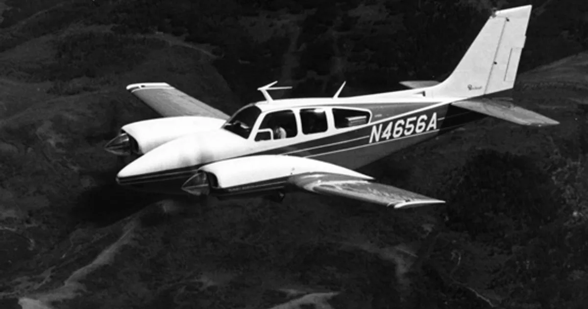



In this document
Dynamic Brake Relay Electrical Function & Connections
Describes the schematic diagram of the brake relay's electrical functions and connections, including terminations to circuit breakers and limit switches.
Dynamic Brake Relay Removal, Maintenance and Reinstallation
Outlines the steps for removing, maintaining, and reinstalling the dynamic brake relay, emphasizing the importance of marking wiring connections.
Relay Internal Mechanisms
Details the internal components of the relay, including solenoids and contacts, and their functions in controlling the landing gear motor.
Cleaning and Polishing Contacts
Provides instructions on how to clean and polish the relay contacts to ensure optimal performance.
Reassembly Process
Describes the reassembly of the relay, highlighting the importance of correct placement of components.
Functional Checks
Advises on performing functional checks after reinstallation, referencing the shop manual procedures.
Summary written by AI from the source document. Check the original before relying on it. See which parts of Sprinkle are written by AI.
Safety notes
- Be careful not to drop terminal nuts and washers during disconnection.
- Ensure the shuttle switch is correctly positioned during reassembly.
- Access to the relay is limited; clean the area to avoid losing parts.
- Pitting on contacts can cause dynamic braking problems.
- Use caution when handling small components to avoid misplacement.
Summary written by AI from the source document. Check the original before relying on it. See which parts of Sprinkle are written by AI.
Full document text
6/3/2017 pg 1 of 13 Dynamic Brake Relay Overhaul.docxx Beech Travel Air Dynamic Brake Relay Overhaul DYNAMIC BRAKE RELAY ELECTRICAL FUNCTION & CONNECTIONS The schematic diagram shows brake relay electrical functions and connections arranged roughly as they correspond to the physical placement of its components. Terminations to circuit breakers, gear limit switches and the landing gear motor are depicted as well so the connections can be compared to the wiring diagrams in the Beech manual. The bottom photos show the actual relay from above and below. DOWN COIL (RIGHT) UP COIL (LEFT) C1 C2 2 1 3 RED (DOWN) TO GEAR MOTOR WHITE (UP) TO GEAR MOTOR UP LIMIT CIRCUIT DOWN LIMIT CIRCUIT LDG GEAR MOTOR C/B BLK (GND) TO GEAR MOTOR DYNAMIC BRAKE RELAY STATE: A/C ON GROUND GEAR SELECTED DOWN GEAR IS DOWN SHUTTLE SWITCH LATCHED DOWN ORIG 1/14/2008 REV 1 1/15/2008 REV 2 2/23/2009 REV 3 5/10/2010 C3 SHUTTLE SWITCH RUN SWITCHES BRAKE SWITCHES THE RUN SWITCHES ARE OPEN AND BRAKE SWITCHES CLOSED WHEN COIL IS INACTIVE THE SHUTTLE SWITCH CONNECTS THE MOTOR BRAKING WINDING & REMAINS “LATCHED” AS LAST POSITIONED BY AN ACTIVE COIL GENERAL LAYOUT Relay is a Cutler- Hammer type 6046H39A NOTE: ‘LEFT’ & ‘RIGHT’ COIL POSITIONS ARE FACING FWD IN AIRPLANE REV 4 6/6/2017 6/3/2017 pg 2 of 13 Dynamic Brake Relay Overhaul.docxx DYNAMIC BRAKE RELAY REMOVAL. MAINTENANCE AND REINSTALLATION 1. The dynamic brake relay is used with the Beechcraft 24 vdc airplanes (Travel Air, Baron and later Bonanzas) to control the high-amperage landing gear motor running and stopping circuits. This overcomes problems with other systems like those in Bonanzas that used only the limit microswitches to control the system directly. The microswitch contacts are unsuited to heavy currents and burn up with normal use, but the relay contacts are much more robust. Our relay was made by Cutler-Hammer in 1962 as p/n 6046H39A. The photos above show the relay as mounted under the right front passenger seat next to the flex heater duct (left) and more fully exposed with the duct and gear motor removed (right). Wiring to the relay connects the related aircraft power circuit breakers, limit switches and the landing gear motor itself. 2. Begin relay removal by marking all the wiring connections, as shown above left. The motor wiring has already been removed in this photo. The wires can be disconnected either with the relay mounted or after removing the two relay mounting screws and lifting the relay from its mounting plate (as shown above right.) If wires are disconnected in place, be very careful not to drop the small terminal nuts and washers down into the underfloor areas since access is quite limited. 6/3/2017 pg 3 of 13 Dynamic Brake Relay Overhaul.docxx 3. This is how the relay looks once removed and on the workbench. The left photo above shows the relay positioned as installed in the airplane, looking from the back seat perspective. The right photo shows the forward side of the relay. Compare these views with the photos at the opening paragraph to better see other connections, the solenoids and related wiring. Terminals are marked with letters and/or numbers (C1, C2, etc.) to denote external connections to other system components. 4. The heavy black jumper wire seen in the top photos must be removed from the inboard two top terminals (above left) to allow removal of the triangular shuttle switch cover and the individual cylindrical solenoid switch covers. Each circular solenoid switch assembly controls a gear up or gear down command from the landing gear handle. As shown, “up” is the left coil; “down” is the right. The photo above right shows the general arrangement of the shuttle switch and the contacts inside the solenoid switch assembly, including those inside the circular cap. The shuttle switch on the vertical bakelite piece between them at the back “latches” in the appropriate position to select either the “up” or “down” motor winding for the braking function when power is removed. When the gear is being raised the “down” motor winding is selected by the shuttle switch for braking, and vice versa. As shown, the switch is positioned for “gear down” without power applied to the relay. The shuttle switch arm is connecting the contacts from upper left to lower right. 6/3/2017 pg 4 of 13 Dynamic Brake Relay Overhaul.docxx 5. With both covers removed the internal mechanisms are visible. Each solenoid moves an upper and lower pair of contacts, insulated by bakelite blocks which are anchored to the solenoid armatures and ride on threaded guide rods. Unpowered, solenoid springs keep the lower contacts open and the upper contacts closed. The left solenoid is the “up” control; the right is “down.” When the gear handle is moved the respective solenoid is energized, closing a lower pair of contacts to operate the gear motor. It also pulls the associated silvery “teeter totter” lever down, tipping the shuttle switch to bridge the appropriate pair of motor winding contacts for dynamic braking. Upon reaching the gear travel stop, the limit switch cuts off the solenoid and the contacts rebound upward to shut off motor power at the lower contacts and short circuit the inactive motor winding to ground with the upper contacts. This causes a brief, large reverse current in the motor which stops it almost instantly. Obviously, if contacts are burned or tarnished their electrical resistance increases. At high currents, even small resistance cause major voltage loss which hinders motor and braking performance. 6/3/2017 pg 5 of 13 Dynamic Brake Relay Overhaul.docxx 6. These photos show more clearly the upper relay contacts and the layout of the lever mechanism that moves the shuttle switch. The contacts exhibit some tarnish and pitting. Each lever is cushioned with a small spring so it only pulls down on the shuttle switch cam when its solenoid is activated. The cam pivot is seen at the hole through the vertical aluminum bracket in the upper right picture.
Show full textShow less
7. The lower view shows the right solenoid contact package disassembled. All the contacts can be removed for polishing by carefully removing the small cotter from the metal button atop the lever and sequentially removing the button, folding back the lever, removing the thin metal washer plus the very tiny centering washers, spring, contact bars with bakelite separator and the lower fiber disc. All these parts are shown to the right of the relay. Once opened up like this, the loose contacts can be closely inspected and polished, and the lower contacts can be removed as well if needed. 6/3/2017 pg 6 of 13 Dynamic Brake Relay Overhaul.docxx 8. The lower contacts, shown above, can also be removed to remove pits and polish the surfaces. Simply remove the nuts from the mounting plate securing the contact (a screw from beneath serves as the threaded stud. – see addendum 1.) As shown at right, each lower contact segment sits in a machined groove and is easily removed. NOTE: Pitting on the upper contacts to this extent WILL cause dynamic braking problems and is not acceptable. All the contact plates and nuts are silver plated and are subject to tarnishing, as can be seen, but they polish up very well using fine files, mild abrasives or chemical means. 9. The shuttle switch contacts, shown above and at para. 5, are also subject to tarnish but aren’t as readily removed. The contact plate is spring loaded so with the relay apart there is good access and it’s easy to insert a fine point file or piece of Scotchbrite to clean up the contacts. While gently pinching the contacts together, slide a business card or similar heavy paper between the contacts for final cleaning. 6/3/2017 pg 7 of 13 Dynamic Brake Relay Overhaul.docxx 10. With everything apart, it’s a good time to brush or blow away dust and debris accumulated in the many nooks and crannies of the relay. Wipe the exterior covers clean and scrub the external connection terminals to remove tarnish and dirt. 11. Reassembly was essentially the reverse process, with careful reference to photographs to arrange washers, springs and other small items in their original configuration. The most tedious part of the process is replacing the tiny washers and spring under each solenoid lever, and then inserting the cotter pins into the small metal buttons. The pins fit rather tightly so if the holes aren’t well aligned or the cotters aren’t straight the cotters won’t go in. Double-check that the shuttle switch is placed in the gear down position, with the contact pivot running from upper left contact to the lower right contact (roughly 10 o’clock to 4 o’clock) as seen at the top of the lower photo on the previous page. 6/3/2017 pg 8 of 13 Dynamic Brake Relay Overhaul.docxx The wiring can be reconnected to the relay either after the relay is mounted back in its tray in the airplane, or beforehand with the relay on the cabin floor just aft of its under-seat location. Clean all the wire terminals. Before mounting the relay in the tray it’s a good idea to clean the area of the debris that always accumulates, and be sure to clean the ground connections. Access in the mounted position is poor and if a nut or washer is dropped into the underfloor area it may be hard to find without removing everything again. A small cloth laid underneath will help avoid losing dropped items. The photos on the previous page show the locations and engraved markings of the terminal connections. The next annotated photo shows which functions are connected to each terminal. 6/3/2017 pg 9 of 13 Dynamic Brake Relay Overhaul.docxx 12. These photos depict the relay mounting tray and the relay installed on it. Access is limited by the gear actuation rods and fuel lines, partly visible. The circular heater duct tee is visible in the left photo. Secure the relay in the tray with its two ground screws; note that 2 wires go to the left screw. Assuming the gear motor is already installed reinstall the flex heater duct to the metal tee. Install the aft upholstery panel and connect the flex duct to its heat outlet with the remaining worm clamp. 13. To complete functional checks, refer to the shop manual procedures about landing gear functional checks. Finally, close up the spar access panels, replace the aft cabin carpet and reinstall the front seats. With suitable inspection and logbook entries from the A&P, the job is done. ALTERNATE RELAY PART NUMBERS According to aircraft salvage house data and FAA service reports, the following relays are more or less interchangeable to use for the same function: Cutler-Hammer (Eaton) 6046H39A (as installed in Travel Air and listed in parts book), Cutler-Hammer (Eaton) 6046H39B, or Cutler-Hammer (Eaton) 6046H58 Cutler-Hammer (Eaton) SM50D7 (used on F33A series with numerous SDR write-ups.) Very similar design using a plastic housing for the contacts, as shown at right. 6/3/2017 pg 10 of 13 Dynamic Brake Relay Overhaul.docxx DYNAMIC BRAKE RELAY ADDENDUM 1 - June 2017 In May 2017 the dynamic brake relay was again overhauled. This section discusses added information not provided in the earlier pages. 1. The solenoid contacts can be effectively cleaned and polished using a small brass rotary wire end brush in an electric drill. This brings the contact surface to higher degree of polish than Scotchbrite or fine sandpaper. Surface roughness is easily removed with light filing first. 2. The shuttle switch assembly can be removed by taking out two screws under the bakelite plate via the access holes through the relay chassis, as shown. The visible screw threads into the shuttle switch base itself. The obscured screw threads into a small attach plate which secures the shuttle and positively locates the bakelite covers over the solenoid contacts. The shuttle switch footprint is seen below after removal with its 2 mounting screw holes. 6/3/2017 pg 11 of 13 Dynamic Brake Relay Overhaul.docxx These photos show the shuttle switch assembly in more detail. The attachment plate is tapped for one of the attaching screws (shown) and provides secure orientation for the cylindrical solenoid contact covers seen in previous pages. The fixed contacts were badly pitted (first photo) but light filing followed with fine sandpaper and then rotary brushing with the brass drill brush brought them to a high polish. The moving contacts on the shuttle arm were polished with fine sandpaper between the contact surfaces by lightly pressing the arm against the fixed contacts while moving the sandpaper. 6/3/2017 pg 12 of 13 Dynamic Brake Relay Overhaul.docxx 3. The lower fixed contacts shown earlier are easily removed for cleaning as shown below. The first photo shows the pitted contacts before removal. First take off the contact nut (top right photo), then loosen the attaching screw from beneath the base plate. The screw threads into the contact itself, shown lower left. The final photo shows the lower fixed contact after cleaning next to its mounting screw, and the mating movable lower contact plate to the left. 4. A good ground connection is critical to proper braking function. The photo shows the relay tray ground screw location, which should be cleaned of paint for the best conductivity. 6/3/2017 pg 13 of 13 Dynamic Brake Relay Overhaul.docxx DYNAMIC BRAKE RELAY ADDENDUM 2 General Notes on 24 vdc Landing Gear Motor & Gearbox Operation 1. The landing gear motor turns about 7500 rpm for 4-5 seconds to extend or retract the gear. This equates to about 7500*4/60 = 500-625 revolutions of the motor. 2. The landing gear gearbox rotates roughly ½ turn for about 500 turns of the motor (rounded off) or 50 turns of the hand crank. This is a 1000:1 reduction for the motor and a 100:1 reduction for the hand crank. 3. When the landing gear is operated the travel limit settings are expressed in terms of 1/8 to ¼ turn of the hand crank away from mechanical stops. Since this is related to 50 crank turns to produce about 180 degrees or ½ turn of sector gear rotation, the stop tolerances equate to about 1/8*1/100 = 1/800 to 1/400 of a full rotation of the sector gear, or roughly 360/800 = about ½ to 1 degree of sector rotation. 4. Assuming 3/4 degree of sector rotation margin for 3/16 turn of hand crank (midway between 1/8 and ¼ turn) before the mechanical stop is reached, and a sector gear diameter of 12 inches, the amount of slack stopping distance around the circumference of the sector gear is roughly 3/16*12*3.1416*1/100 = .071 inch. 5. Figuring the opposite way back to the motor, this tolerance requires the motor to come to a complete stop from 7500 rpm leaving roughly 3/16*1000/100 = 2 turns of the motor before reaching the mechanical stops. This implies a motor rotational accuracy error of 2/500, about 0.4%. If the limit microswitches electrically actuate 1/8 inch before the sector gear actually stops, at a switch radius point of about 4 inches, this means the motor coasts about 5 turns during the braking process (1000/(8*8*3.1416) = 5), taking about 1/12 second (assume 7500 rpm linear deceleration to zero, average = 3750 rpm; 5*60/3750 = .08 second.) 6. Paragraph 5 makes it clear why low resistance in the dynamic brake circuit is so critical to proper gear limit adjustments. To stop the motor so quickly the braking surge current is very high, say 10 times the normal operating level. If the circuit resistance is, say, only 0.05 ohms, either at the motor connections, motor brushes or the brake relay contacts, this would still pass most of the normal running voltage at 20 amps (24 – 20*0.05 = 23 vdc). So the gear transit times would be reasonable. But for braking, the 0.05 ohms would dissipate much of the induced reverse voltage at 200 amps (200 * 0.05 = 10 vdc lost) so stopping quickly and consistently becomes problematic. NOTE: This was confirmed in actual experience, when only one of four upper relay contacts was found pitted, that being enough to ruin dynamic braking at the “up” gear limit even after a shop overhaul of the gear motor. Dressing the contacts smooth completely solved the problem.