BEECHCRAFT KING AIR 90 SERIES AUXILIARY FUEL TANKS ICA MANUAL
Beechcraft King Air C90GTx · Parts Catalog
Overview
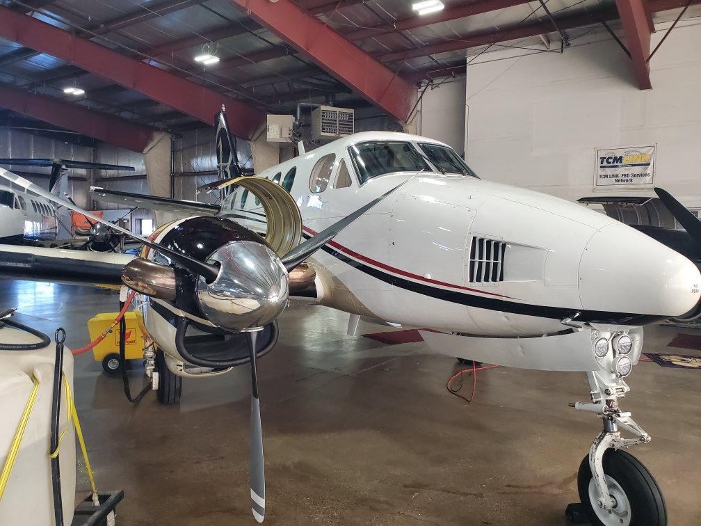
This Instructions for Continued Airworthiness (ICA) manual provides essential information for the Beechcraft King Air 90 series airplanes modified with CenTex Aerospace’s Saddle Tank STC. It details the installation and maintenance of auxiliary fuel tanks, known as saddle tanks, which are mounted on the wings behind each engine nacelle. The manual outlines the necessary procedures for ensuring the continued airworthiness of the aircraft, including maintenance checks, servicing, and troubleshooting of the auxiliary fuel system. It serves as a critical resource for maintenance personnel and operators to ensure compliance with FAA regulations and safe operation of the modified aircraft.
- The auxiliary saddle tanks have a capacity of 90 gallons each, installed behind each engine nacelle.
- Fuel drain hoses must be replaced every 10 years as part of maintenance.
- The saddle tanks should be filled last, ensuring wing and nacelle tanks are full beforehand.
- The fuel system allows for gravity feeding from the saddle tanks to the center fuel tank.
- Optical fuel level sensors indicate fuel levels with LED lights, changing from green to amber as levels drop.
Document
Source
Originally published by www.centex.aero. Sprinkle hosts a reference copy with an added summary, specifications and searchable full text.
Document details
- Type
- Parts Catalog
- Year
- 2021
- Pages
- 90
- File size
- 2.9 MB
- Publisher
- www.centex.aero
Common. Rarer than 0% of the aircraft models we track.
Most owners only have the POH. Here's the essential set for the Beechcraft King Air C90GTx.
- Pilot's Operating Handbook / AFM
- Checklist
- Maintenance Manual
- Parts Catalog (IPC)
- Systems & Wiring
- Service Bulletins
- Type Certificate (TCDS)
Beechcraft King Air C90GTx for sale now


Free — save the C90 to your watchlist and track it in one place.
More Beechcraft King Air C90GTxmanuals & documents
See all 19 →- AAIB Bulletin: 11/2024Other Documents
- AAIB Bulletin: 11/2024Other Documents
- KING AIR C90GTxSpecifications
- IM199-90 INSTALLATION MANUAL WITH IPL FOR CONVERSION KIT PART NO. 199-90Flight Manual
- BEECHCRAFT KING AIR 90 SERIES AUXILIARY FUEL TANKS ICA MANUALParts Catalog
- KING AIR C90GTxOther Documents
- 2008 King Air C90GTi Specifications and SummarySpecifications
- G1000/GFC 700 Post Installation Checkout Procedure – Hawker / Beechcraft King Air C90Flight Manual
- GWX 68 Weather Radar Installed in Beech Queen Air/King Air Series STC Master Data ListChecklist
- GWX 68 Installation DataType Certificate
- AIRWORTHINESS DIRECTIVE AD/BEECH 90/22 Amdt 3Airworthiness Directives
- SCHEDULE OF AIRWORTHINESS DIRECTIVESAirworthiness Directives
If you fly the Beechcraft King Air C90GTx, you may also be researching these.

In this document
Introduction
The introduction outlines the purpose of the ICA manual, which is to provide instructions for the continued airworthiness of Beechcraft King Air 90 series airplanes modified by the Saddle Tank STC. It describes the installation of 90-gallon auxiliary fuel tanks and provides associated drawings for reference.
Airworthiness Limitations
This section specifies the maintenance required under FAA regulations for King Air 90 airplanes with the CenTex Aerospace auxiliary fuel saddle tanks installed. It confirms that there are no changes to the original airworthiness limitations established by Beechcraft.
Maintenance Checks
The manual includes a detailed overhaul and replacement schedule for auxiliary tank components, specifying that fuel drain hoses should be replaced every 10 years. It also outlines a scheduled inspection program that aligns with Beechcraft’s maintenance manuals.
Servicing
This section provides procedures for servicing the auxiliary fuel tanks, including filling and draining the tanks. It emphasizes that the saddle tanks should be filled last and outlines the proper procedures to avoid overfilling.
Fuel System Description and Operation
The fuel system section describes how the saddle tanks are integrated into the existing fuel system, detailing the connections and modifications made to allow gravity feed into the center section fuel tank. It also explains the function of the optical fuel level sensors.
Safety notes
- Ensure that the saddle tanks are not overfilled beyond their specified capacity.
- Regular inspections of the fuel system are critical to prevent fuel flow issues.
Full document text
Waco Regional Airport ● P.O. Box 5500 ● Waco, Texas 76708 Beechcraft King Air 90 Series AUXILIARY FUEL INSTRUCTIONS FOR CONTINUED AIRWORTHINESS ICA Manual No. 26005-30 Revision 2 January 2021 BEECHCRAFT KING AIR 90 SERIES AUXILIARY FUEL TANKS ICA MANUAL MANUAL No. 26005-30 Rev. 1, 09/01/14 RECORD OF REVISIONS Rev. No. Date Inserted By Rev. No. Date Inserted By Rev. No. Date Inserted By When a revision to this manual is issued, insert the revised or added pages into the manual. Record the revision number, date inserted, and the initials of the person responsible for the update on this page. BEECHCRAFT KING AIR 90 SERIES AUXILIARY FUEL TANKS ICA MANUAL MANUAL No. 26005-30 Rev. 1, 09/01/14 [Intentional Blank Page] BEECHCRAFT KING AIR 90 SERIES AUXILIARY FUEL TANKS ICA MANUAL MANUAL No. 26005-30 Rev. 2, Jan. 2021 REVISION LOG Rev. No. Rev. Date Change Description Page(s) Affected 1 9/1/14 ADD KING AIR 90 SERIES ELIGIBILITY. ALL 2 JAN. 2021 INTRODUCTION - UPDATE GENERAL INFORMATION. 1-3 CH. 4 - UPDATE AW. LIM. FORMAT; ADD BEECHCRAFT MANUAL REF. 5 CH. 5 - UPDATE INFO., FORMAT & INSPECTION TIMES SIMILAR TO KA200/300. 7-10 CH. 11 - UPDATE INFO.; ADD PLACARD ILLUSTRATIONS. 11-13 CH. 12 - ADD FUEL SYSTEM DETAILS; ADD LANDING GEAR SERVICING. 15 CH. 28 - ADD SECTIONS GENERAL, CONTENTS, DESCRIPTION AND OPERATION, FILLER CAP INSP., FUEL SCREEN CLEANING, LEAK REPAIR, MATERIALS, AND INDICATOR REMOVAL & INSTL.; ADD VENT BLOCKAGE TO TROUBLESHOOTING; ADD DETAILS TO FAIRING REMOVAL & INSTL. (WAS CH. 54), FUEL SCREEN INSP., REMOVAL & INSTL., CHECK VALVE INSP. & REPL., TANK INSTL., LEAK TEST, FUNCTIONAL TEST, AND OPTICAL LEVEL SWITCH REMOVAL & INSTL.; ADD AMBER LED TROUBLESHOOTING INFO.; ADD FIGS. 4 & 5. 19-31 BEECHCRAFT KING AIR 90 SERIES AUXILIARY FUEL TANKS ICA MANUAL MANUAL No. 26005-30 Rev. 2, Jan. 2021 [Intentional Blank Page] BEECHCRAFT KING AIR 90 SERIES AUXILIARY FUEL TANKS ICA MANUAL MANUAL No. 26005-30 Rev. 2, Jan. 2021 LIST OF EFFECTIVE PAGES Section Pages Rev. No. Date Section Page Rev. No. Date Title Title 2 1/21 Record of Revisions Record of Revisions 1 9/1/14 Revision Log Revision Log 2 1/21 List of Eff. Pages List of Eff. Pages 2 1/21 Introduction 1-4 2 1/21 Ch. 4, AW Limitations 5-6 2 1/21 Ch. 5, TL/ Maint. Checks 7-10 2 1/21 Ch. 11, Plcds. & Markings 11-14 2 1/21 Ch. 12, Servicing 15-16 2 1/21 Ch. 24, Electrical Pwr. 17-18 2 1/21 Ch. 28, Fuel 19-32 2 1/21 Apdx. A, Illustr. Parts Catalog A1-A38 1 9/1/14 Apdx. B, Wiring Diagram Manual B1-B12 1 9/1/14 BEECHCRAFT KING AIR 90 SERIES AUXILIARY FUEL TANKS ICA MANUAL MANUAL No. 26005-30 Rev. 2, Jan. 2021 [Intentional Blank Page] BEECHCRAFT KING AIR 90 SERIES AUXILIARY FUEL TANKS ICA MANUAL PAGE 1 MANUAL No. 26005-30 INTRODUCTION Rev. 2, Jan. 2021 INTRODUCTION GENERAL This ICA Manual provides the Instructions for Continued Airworthiness (ICA) for Beechcraft King Air 90 series airplanes modified by CenTex Aerospace’s (CTA) Saddle Tank STC. The Saddle Tank STC modification installs auxiliary fuel tanks, called “saddle tanks,” on the wing, behind each engine nacelle as approved under FAA Supplemental Type Certificate (STC) number SA11142SC. ASSOCIATED DRAWINGS The following CenTex Aerospace drawings are provided to install the auxiliary fuel tanks on the airplane. These drawings are listed as reference and are not required for maintaining the continued airworthiness of the airplane. Contact CenTex Aerospace for assistance in obtaining a copy of a specific drawing. Number Title 26005-2000 INSTALLATION, AUXILIARY FUEL TANK 26005-3000 INSTALLATION, NACELLE FAIRING, AUXILIARY FUEL TANK ASSEMBLY 26005-4000 INSTALLATION, FUEL SYSTEM MOD., AUXILIARY FUEL TANK ASSEMBLY 26005-5001 WIRING DIAGRAM, FUEL LEVEL INDICATION, AUXILIARY FUEL TANK 26005-6000 INSTALLATION, FUEL LEVEL INDICATION, AUXILIARY FUEL TANK ASSEMBLY 26005-7000 INSTALLATION, PLACARDS, AUXILIARY FUEL TANK ASSEMBLY 26005-8000 TANK REMOVAL & NACELLE SKIN REINSTALLATION DESCRIPTION OF MODIFICATION The Saddle Tank STC installs a set of the following saddle tanks on the airplane: 90-gallon full fuel tanks (ST180 tanks) The aluminum auxiliary fuel saddle tanks are mounted on the upper wing behind the engine nacelles. The saddle tanks are secured to the upper wing structure with five (5) AN4 (1/4 inch dia.) bolts and the existing nacelle structure with sixteen (16) AN525-832 (#8) screws. An aluminum fairing between the engine nacelle and tank provides a smooth transition for air flow around the saddle tank. An door on top of the fairing provides access to the nacelle tank filler cap. Exterior placards mark the saddle tank fillers, nacelle filler access, and fuel drains added for this conversion. The existing fuel system is modified so that fuel from the saddle tank can gravity feed into the ship’s center section fuel tank. A fuel supply line at the bottom of the saddle tank goes through the landing gear wheel well and connects to the fuel line located between the main wing interconnect line and the nacelle tank, downstream of the interconnect check valve. See Figure 1 on the next page for the modified aircraft fuel system schematic. See Figure 1a on the next page for a layout of the saddle tank fuel system. A smaller check valve in the saddle tank fuel line prevents fuel from migrating back into the saddle tank. Drain valves in the saddle tank and the fuel supply line (aft wheel well area of nacelle) allows the tank to be sumped and drained. The auxiliary fuel saddle tanks each have an inlet and outlet vent line protruding up from the tank floor. The vent lines open at the top of the expansion space in the tank near the fuel filler adapter. The saddle tanks vent through the ship’s fuel vent system. The saddle tank vent lines connect to the existing vent lines behind the main spar in the main landing gear wheel well. BEECHCRAFT KING AIR 90 SERIES AUXILIARY FUEL TANKS ICA MANUAL PAGE 2 MANUAL No. 26005-30 INTRODUCTION Rev. 2, Jan. 2021 Figure 1. Fuel System Schematic
Show full textShow less
Figure 1a. Fuel System (LH side looking inboard) The saddle tanks each include five optical fuel level sensors connected to an indicator unit mounted to the pilot’s side wall. The indicator has five LED indicators for each tank, corresponding to an individual level sensor. When fuel is at or above the indicated level, the LED illuminates green. As fuel drops below each level sensor, the LED extinguishes with the exception of the last LED, which changes from green to amber. Refer to the individual chapters in this manual for additional details and illustrations of saddle tank components and systems. F F F FLUSH VENT AUXILIARY FUEL TANK (90 GALLONS USABLE) WING TANKS (TOTAL 128 GALLONS USABLE) NACELLE TANK (57 GALLONS USABLE) 40 GAL 25 GAL 23 GAL 40 GAL 57 GAL VENT VENT SUMP & DRAIN UNDER BOOST PRESSURE SUPPLY (EXISTING TANKS) SUPPLY (AUXILIARY TANK) RETURN VENT LINES FUEL PUMP CHECK VALVE FUEL TANK FILLER ISOLATION DRAIN VALVE 90 GAL NEW CHECK VALVE D D D NEW TEE CENTER SECTION WING TANK D NEW DRAIN VALVE VENT EXISTING VENT LINE FUEL TANK VENT LINE (IN) FUEL TANK VENT LINE (OUT) FUEL SCREEN FUEL DRAIN LINE FUEL LINES CHECK VALVE & FUEL LINES 45° FITTING ACCESS DOOR EXISTING FUEL LINE FROM WING TANKS FUEL TANK FWD WHEEL WELL EXISTING CHECK VALVE BEECHCRAFT KING AIR 90 SERIES AUXILIARY FUEL TANKS ICA MANUAL PAGE 3 MANUAL No. 26005-30 INTRODUCTION Rev. 2, Jan. 2021 MAINTENANCE Airworthiness limitations, inspection procedures, servicing information, and maintenance procedures provided in this manual apply to the equipment and modifications associated with this STC and supplement the Beechcraft King Air 90 Series Maintenance Manual (AMM). For King Air 90 series aircraft modified by this STC, follow the inspection, servicing, and maintenance procedures in the AMM, except as provided herein. This manual uses the same chapter numbering and general format as the AMM. For standard aviation maintenance practices, such as cutting, splicing, and replacing wire, routing and securing lines, inspecting electrical wiring and equipment, etc. use the techniques and practices found in FAA Advisory Circular AC 43.13-1B/2B or later FAA approved revision. REPLACEMENT PARTS Appendix A of this manual includes illustrated parts lists for the equipment specified herein. Contact CenTex Aerospace for replacement parts. WIRING DIAGRAMS Appendix B of this manual includes wiring diagrams for the systems specified herein. MANUAL UPDATES A copy of this ICA Manual is provided with the STC upon installation. When changes to this ICA Manual are made, CenTex Aerospace will provide updates to the registered airplane owner by email or direct mail. Contact CenTex Aerospace to make other arrangements. If there is a change in airplane ownership or operator, please notify CenTex Aerospace in order to keep all contact information current. The changes to the ICA manual will be identified by revision number and date in the Revision Log. CenTex will provide the owner with the revised pages, a Revision Log, and an updated List of Effective Pages. The owner, or responsible party, will add or replace the pages affected by the revision and make an entry in the Record of Revisions in order to document the update to the ICA Manual is accomplished. ASSISTANCE For assistance with continuing airworthiness issues or any other issues related to this STC, contact Centex Aerospace at the following address or telephone number. Centex Aerospace Inc. 7925 Karl May Drive Waco, Texas 76708 (254) 752-4290 http://www.centex.aero/ BEECHCRAFT KING AIR 90 SERIES AUXILIARY FUEL TANKS ICA MANUAL PAGE 4 MANUAL No. 26005-30 INTRODUCTION Rev. 2, Jan. 2021 [Intentional Blank Page] BEECHCRAFT KING AIR 90 SERIES AUXILIARY FUEL TANKS ICA MANUAL PAGE 5 MANUAL No. 26005-30 CHAPTER 4 Rev. 2, Jan. 2021 CHAPTER 4 The Airworthiness Limitations section is FAA approved and specifies maintenance required under §§43.16 and 91.403 of the Federal Aviation Regulations unless an alternative program has been FAA approved. Beechcraft King Air 90 airplanes with CenTex Aerospace auxiliary fuel saddle tanks installed under STC SA11142SC have no changes or additions to the original Airworthiness Limitations established by Beechcraft. For airplane component life limits or structural inspections, refer to the applicable Beechcraft manual. BEECHCRAFT KING AIR 90 SERIES AUXILIARY FUEL TANKS ICA MANUAL PAGE 6 MANUAL No. 26005-30 CHAPTER 4 Rev. 2, Jan. 2021 [Intentional Blank Page] BEECHCRAFT KING AIR 90 SERIES AUXILIARY FUEL TANKS ICA MANUAL PAGE 7 MANUAL No. 26005-30 CHAPTER 5 Rev. 2, Jan. 2021 CHAPTER 5 TIME LIMITS/MAINTENANCE CHECKS GENERAL The overhaul and replacement schedule and inspection programs in this chapter apply to the equipment installed as part of this STC. The format of the inspection programs is the same as those in Beechcraft’s maintenance manuals and maintenance manual supplements. The terminology (phase, detailed, biennial, etc.) used in this chapter has the same meaning as Beechcraft’s terminology. Use the AMM guidelines when following the replacement and inspection schedules specified herein. Use the Saddle Tank Inspection sheet in this chapter to record the completion of each required inspection item at the time of the scheduled inspection (phase 1, 2, 3, etc.). Retain this sheet with the normal aircraft maintenance records. OVERHAUL AND REPLACEMENT SCHEDULE The following auxiliary tank components should be replaced no later than the recommended period. ITEM OVERHAUL OR REPLACE Fuel drain hoses Replace every 10 years SCHEDULED INSPECTION PROGRAM For King Air 90 series airplanes following a scheduled inspection program in the Beechcraft Maintenance Manual, inspect the saddle tank items during the inspection marked below. ITEM (1) PHASE INSP BIENNIAL INSP 1 2 3 4 INT COMP Exterior placards X X X X X X Fuel drains operational check X X X X X X Fuel level indicator X X Fuel level indicator operational check X X X X X X Fuel level indicator placard X X X X X X Fuel level sensors X X X Saddle tanks X X X X X X Saddle tank fairings X X X Saddle tank plumbing X X NOTES: (1) See the Saddle Tank Inspection sheet in this chapter for inspection details. BEECHCRAFT KING AIR 90 SERIES AUXILIARY FUEL TANKS ICA MANUAL PAGE 8 MANUAL No. 26005-30 CHAPTER 5 Rev. 2, Jan. 2021 [Intentional Blank Page] BEECHCRAFT KING AIR 90 SERIES AUXILIARY FUEL TANKS ICA MANUAL PAGE 9 MANUAL No. 26005-30 CHAPTER 5 Rev. 2, Jan. 2021 SADDLE TANK INSPECTION Owner ___________________________________ Total Time __________ Total Cycles _________ W.O. No. _________________________________ Date In ____________ Date Out ____________ Serial No. ______________ Reg. No. __________ STC Installed TIS ________ Cycles _______ Inspection (1,2,3,4,INT,COMP): _______________ NOTE: Inspect only the items required by the applicable phase or other inspection as designated by an “X” in the inspection program table. Write “N/A” if an item is not required for the applicable inspection. A. PILOT COMPARTMENT REFERENCE MECH INSP 1. FUEL LEVEL INDICATOR PLACARD - Check placard for proper adhesion, visibility, signs of damage. 26005-30 Ch. 11 2. FUEL LEVEL INDICATOR - Check security of attachment. Check connectors & wiring for damage, chafing and security. 26005-30 Ch. 28 B. LEFT WING REFERENCE MECH INSP 1. EXTERIOR PLACARDS - Check placards for proper adhesion, visibility, signs of damage. 26005-30 Ch. 11 2. SADDLE TANK - Check tank exterior for loose rivets, fasteners, damage & leaks. Check wing mounting bolts (5) for security & proper installation. Inspect fuel cap for damage and attachment. Inspect the visible fuel cap packing for flexibility, splits, cracks, or distortion. 26005-30 Ch. 28 3. SADDLE TANK FAIRING - Remove fairing. Check for security, missing fasteners & damage. 26005-30 Ch. 28 4. SADDLE TANK PLUMBING - Check fuel and vent lines for leaks, security of attachment & signs of damage. 26005-30 Ch. 28 5. FUEL LEVEL SENSORS - With fairing removed, check saddle tank optical level switches (5) for damage & leaks at mounting holes. Check connectors & wiring for damage, chafing and security. 26005-30 Ch. 28 BEECHCRAFT KING AIR 90 SERIES AUXILIARY FUEL TANKS ICA MANUAL PAGE 10 MANUAL No. 26005-30 CHAPTER 5 Rev. 2, Jan. 2021 C. RIGHT WING REFERENCE MECH INSP 1. EXTERIOR PLACARDS - Check placards for proper adhesion, visibility, signs of damage. 26005-30 Ch. 11 2. SADDLE TANK - Check tank exterior for loose rivets, fasteners, damage & leaks. Check wing mounting bolts (5) for security & proper installation. Inspect fuel cap for damage and attachment. Inspect the visible fuel cap packing for flexibility, splits, cracks, or distortion. 26005-30 Ch. 28 3. SADDLE TANK FAIRING - Remove fairing. Check for security, missing fasteners & damage. 26005-30 Ch. 28 4. SADDLE TANK PLUMBING - With fairing removed, check fuel and vent lines for leaks, security of attachment & signs of damage. 26005-30 Ch. 28 5. FUEL LEVEL SENSORS - With fairing removed, check saddle tank optical level switches (5) for damage & leaks at mounting holes. Check connectors & wiring for damage, chafing and security. 26005-30 Ch. 28 D. OPERATIONAL INSPECTION REFERENCE MECH INSP 1. FUEL LEVEL INDICATOR – Check the indicator during start and run of the engine to verify the LEDs illuminate according to the level of fuel in the saddle tanks. Conduct the "System Functional Test" only if necessary for troubleshooting or checking indicator function. 26005-30 Ch. 28 2. FUEL DRAINS - Check saddle tank fuel drain valves (4) for proper operation. 26005-30 Ch. 28 INSPECTION COMPLETED I certify that this inspection was performed in accordance with the CenTex Saddle Tank Equipment Inspection Program and that the airplane is approved for return to service: MECHANIC: _____________________________ CREW CHIEF: __________________________________ INSPECTOR: ____________________________ DATE: ________________________________________ BEECHCRAFT KING AIR 90 SERIES AUXILIARY FUEL TANKS ICA MANUAL PAGE 11 MANUAL No. 26005-30 CHAPTER 11 Rev. 2, Jan. 2021 CHAPTER 11 PLACARDS AND MARKINGS PLACARDS AND MARKINGS – DESCRIPTION AND OPERATION The placards and markings added to the airplane for this STC are located in the areas indicated below. Interior placards are in location A. Exterior placards are in locations B, C, D. INTERIOR PLACARDS AND LIMITATION MARKINGS Location A – Fuel Panel: The placard on the fuel level indicator, located next to the pilot’s seat, shows the quantity for each of the five fuel level sensors in both the left and right auxiliary fuel saddle tanks. Refer to the CTA airplane flight manual supplement for this STC. C D B A SADDLE TANKS QTY (GALS) 50 75 90 20 0 LH RH 50 75 90 20 0 Placard Fuel level indicator assembly BEECHCRAFT KING AIR 90 SERIES AUXILIARY FUEL TANKS ICA MANUAL PAGE 12 MANUAL No. 26005-30 CHAPTER 11 Rev. 2, Jan. 2021 NACELLE TANK USE JET FUEL SEE PILOTS OPERATING MANUAL FOR FUEL DESIGNATIONS CAPACITY: 57 U.S. GAL. EXTERIOR PLACARDS AND MARKINGS Location B – Top of Saddle Tank & Nacelle Tank Filler Access Door: 1) Fuel Placard – located on top of each saddle tank, behind the fuel filler cap. 2) Nacelle Tank Filler Access Placard – located on door on top of fairing. SADDLE TANK FUEL USE JET FUEL SEE PILOTS OPERATING MANUAL FOR FUEL DESIGNATIONS CAPACITY: 90 U.S. GAL. WITH WINGS LEVEL NACELLE & MAIN TANKS MUST BE FULL BEFORE FILLING SADDLE TANK NACELLE TANK FILLER ACCESS SADDLE TANK FUEL USE JET FUEL SEE PILOTS OPERATING MANUAL FOR FUEL DESIGNATIONS CAPACITY: 90 U.S. GAL. WITH WINGS LEVEL NACELLE & MAIN TANKS MUST BE FULL BEFORE FILLING SADDLE TANK 7.3 3.7 4.5 1.4 NACELLE TANK FILLER ACCESS Fuel Placard Nacelle Tank Filler Access Door Saddle Tank Filler Fairing Placard BEECHCRAFT KING AIR 90 SERIES AUXILIARY FUEL TANKS ICA MANUAL PAGE 13 MANUAL No. 26005-30 CHAPTER 11 Rev. 2, Jan. 2021 Location C – Bottom of Saddle Tank Sump Drain: Location D – Inboard Wheel Well Nacelle Drain: Drain Placard – located adjacent to the saddle tank sump drain and fuel line drain. PLACARDS AND MARKINGS - MAINTENANCE PRACTICES Inspect placard for damage and wear. Replace placard if it becomes illegible or is peeling or delaminating. FUEL DRAIN FUEL DRAIN 3.5 .7 Fuel Line Drain Saddle Tank Drain Placard Nacelle Drain Placard Saddle Tank Sump Drain BEECHCRAFT KING AIR 90 SERIES AUXILIARY FUEL TANKS ICA MANUAL PAGE 14 MANUAL No. 26005-30 CHAPTER 11 Rev. 2, Jan. 2021 [Intentional Blank Page] BEECHCRAFT KING AIR 90 SERIES AUXILIARY FUEL TANKS ICA MANUAL PAGE 15 MANUAL No. 26005-30 CHAPTER 12 Rev. 2, Jan. 2021 CHAPTER 12 SERVICING GENERAL In addition to the servicing information and procedures specified in the Beechcraft King Air 90 Series Maintenance Manual, follow the procedures below for equipment installed as part of this STC. REPLENISHING FUEL SYSTEM SERVICING FILLING THE TANKS Saddle Tanks 1) Fill the saddle tanks last. The saddle tank fuel caps are located on top of the tank, behind the nacelles. Verify both nacelle and wing tanks are full before filling the saddle tanks. 2) Do not fill the saddle tank beyond its specified capacity or above the bottom of the standpipe in the filler port. DRAINING THE FUEL SYSTEM Saddle Tanks Drain the saddle tanks through the either of the two saddle tank drains or use the main fuel system drain. LANDING GEAR SERVICING LANDING GEAR Shock Absorbers / Strut Servicing Include full fuel in the saddle tanks when checking and adjusting the nose strut and main strut extension. BEECHCRAFT KING AIR 90 SERIES AUXILIARY FUEL TANKS ICA MANUAL PAGE 16 MANUAL No. 26005-30 CHAPTER 12 Rev. 2, Jan. 2021 [Intentional Blank Page] BEECHCRAFT KING AIR 90 SERIES AUXILIARY FUEL TANKS ICA MANUAL PAGE 17 MANUAL No. 26005-30 CHAPTER 24 Rev. 2, Jan. 2021 CHAPTER 24 ELECTRICAL POWER ELECTRICAL LOAD DISTRIBUTION - MAINTENANCE PRACTICES In addition to the information specified in the Beechcraft King Air 90 Series Maintenance Manual, the following electrical load data applies for the equipment installed as part of this STC. ELECTRICAL LOAD UTILIZATION CHARTS The equipment installed as part of this STC adds the following continuous loads. ELECTRICAL EQUIPMENT Equipment No. Units Used Load Ea. Unit Amps DC Total Load Amps DC Total Load per System Amps DC Notes FUEL LEVEL INDICATION SYSTEM 0.30 1 Optical level switches 10 0.008 0.08 LED indicators 10 0.020 0.20 Relay 2 0.010 0.02 Notes: 1) The fuel level indication system is added to the existing fuel gauge circuit. BEECHCRAFT KING AIR 90 SERIES AUXILIARY FUEL TANKS ICA MANUAL PAGE 18 MANUAL No. 26005-30 CHAPTER 24 Rev. 2, Jan. 2021 [Intentional Blank Page] BEECHCRAFT KING AIR 90 SERIES AUXILIARY FUEL TANKS ICA MANUAL PAGE 19 MANUAL No. 26005-30 CHAPTER 28 Rev. 2, Jan. 2021 CHAPTER 28 FUEL GENERAL Follow the basic fuel system information and procedures specified in the Beechcraft Maintenance Manual. Follow the procedures in this chapter for equipment installed as part of this STC. CONTENTS SADDLE TANK FUEL SYSTEM – DESCRIPTION AND OPERATION SADDLE TANK FUEL SYSTEM – TROUBLESHOOTING SADDLE TANK FUEL SYSTEM – MAINTENANCE PRACTICES FUEL FILLER CAP INSPECTION FAIRING REMOVAL AND INSTALLATION FUEL SCREEN INSPECTION FUEL SCREEN REMOVAL AND INSTALLATION FUEL SCREEN CLEANING CHECK VALVE INSPECTION AND REPLACEMENT SADDLE TANK REMOVAL SADDLE TANK INSTALLATION SADDLE TANK LEAK TEST SADDLE TANK LEAK REPAIR SADDLE TANK MATERIALS SADDLE TANK FUEL INDICATING SYSTEM – DESCRIPTION AND OPERATION SADDLE TANK FUEL INDICATING SYSTEM – TROUBLESHOOTING SADDLE TANK FUEL INDICATING SYSTEM – MAINTENANCE PRACTICES FUEL LEVEL INDICATING SYSTEM FUNCTIONAL TEST FUEL LEVEL INDICATOR REMOVAL AND INSTALLATION OPTICAL LEVEL SWITCH REMOVAL – FRONT BULKHEAD (3 PLCS) OPTICAL LEVEL SWITCH REMOVAL – AFT BULKHEAD (2 PLCS) OPTICAL LEVEL SWITCH INSTALLATION BEECHCRAFT KING AIR 90 SERIES AUXILIARY FUEL TANKS ICA MANUAL PAGE 20 MANUAL No. 26005-30 CHAPTER 28 Rev. 2, Jan. 2021 SADDLE TANK FUEL SYSTEM – DESCRIPTION AND OPERATION The Saddle Tank STC adds a pair of all-aluminum, external fuel tanks connected directly to flow through an integral strainer into each wing fuel tank by gravity. Refer to the fuel system diagram in Figure 1 on page 2. The functions of the airplane’s wing and nacelle fuel systems are unchanged by the addition of the saddle tanks. The saddle fuel tanks are mounted behind each engine nacelle to the upper surface of the wing. Five ¼-inch (AN4) bolts hold each tank to the wing. Also, sixteen screws attach the front of the tank to the engine nacelle structure. Each tank has its own filler opening located on top of the saddle tank and a sump drain at the lower, aft end of the saddle tank. The main fuel line from the saddle tank goes through the back of the wheel well and enters at the airplane fuel system through a modified line located between the main interconnect line and the nacelle tank as shown in Figure 1a on page 2. There is a low-point drain for the saddle tank fuel line at the aft, inboard side of the nacelle fairing. There is also a check valve in the saddle tank fuel line to prevent fuel migratrating from the wing tank into the saddle tank. Ventilation for the saddle tank is provided by the airplane’s existing vent system. The existing vent line, running from the center section wing tank to the outer wing and nacelle tanks, is modified and routed up, through the wing and into the saddle tank as shown in Figure 1a on page 2. SADDLE TANK FUEL SYSTEM – TROUBLESHOOTING If the saddle tank auxiliary fuel system is not working properly, consult Chart 1 below for possible problem indicators, causes and solutions. Use this chart in conjunction with the procedures in Fuel - Maintenance Practices. Chart 1. Troubleshooting Fuel System Indication Possible Cause Remarks 1) Fuel from saddle tank not transferring to center wing tanks. a) Tank outlet screen assembly (finger screen) is blocked. b) Check valve not opening. a) Follow procedure to inspect and clean or replace screen assembly. b) Clean, repair, or replace check valve. 2) Fuel from saddle tank slow or hesitant in transferring to center wing tanks. a) See possible causes above. b) Blockage in ventilation system. a) See remarks above. b) Inspect vent lines and vent openings for blockage. BEECHCRAFT KING AIR 90 SERIES AUXILIARY FUEL TANKS ICA MANUAL PAGE 21 MANUAL No. 26005-30 CHAPTER 28 Rev. 2, Jan. 2021 SADDLE TANK FUEL SYSTEM - MAINTENANCE PRACTICES The saddle tanks may need to be checked for dirt or debris to prevent restrictions to the fuel flow. If noticeable amount of debris is found at the outlet screen in the fuel tank, it is advisable to also inspect the check valve inside wheel well. To check the fuel screen, follow the steps below. FUEL FILLER CAP INSPECTION Visually inspect the fuel filler cap. Open the cap. Verify the cotter pin and lanyard are secure. Check all visible packings to make sure they are in good condition. Check the outer packing for flexibility, splits, cracks or distortion. If the packing is damaged, replace the fuel filler cap. FAIRING REMOVAL AND INSTALLATION In order to access the front of the saddle fuel tank or to remove the tank, remove the fairing between the engine nacelle and saddle tank as follows. a. Remove existing access panels on the inboard and outboard sides of the nacelle. b. Remove #8 screws, washers & nuts securing the fairing to the nacelle (20 each). c. Remove the remaining screws securing the fairing to the top of the nacelle firewall, nacelle, fairing support brackets, and saddle tank. d. Carefully pull the fairing off so as to avoid scratching the wing or nacelle. e. Check the fairing for condition. Repair dents or damage to sheet metal per Beechcraft AMM. f. To install fairing, place it back on the saddle tank and nacelle. g. Fasten the fairing to the saddle tank, support brackets, and nacelle using the original hardware. h. Reinstall the access panels removed from the nacelle. FUEL SCREEN INSPECTION a. Lower wing flaps (full down). b. Disconnect all electrical power from the airplane. c. Make sure existing wing tank is empty or below 1/8 capacity. d. Drain all fuel from the saddle tank. e. Remove the screws holding the lower, aft close-out panel on the bottom of the tank in order to get to the aft tank access panel. Remove the close-out panel. f. On the aft tank access panel, disconnect the optical level switch harness at the 3-pin connector. g. Remove 20 ea. AN3 bolts, washers, and lock washers or safety wire securing the access panel. Remove the access panel and seal. h. Check the fuel screen at the aft, inboard corner of the tank for damage and blockage. Remove any debris. i. To remove or replace the screen assembly, follow the removal and installation procedures below. j. Inspect the interior of the tank and remove any debris. k. Inspect the access panel seal for damage. Replace as necessary. BEECHCRAFT KING AIR 90 SERIES AUXILIARY FUEL TANKS ICA MANUAL PAGE 22 MANUAL No. 26005-30 CHAPTER 28 Rev. 2, Jan. 2021 l. Reinstall the access panel and seal with 20 ea. AN3 bolts, washers, and lock washers; or secure with safety wire. m. Reconnect the optical level switch harness at the 3-pin connector. Make sure the wire harness is in good condition and secure. n. Reinstall the close-out panel on the tank using the original screws. FUEL SCREEN REMOVAL AND INSTALLATION a. Should the fuel screen need to be removed for further inspection or to be replaced, follow instructions under SADDLE TANK REMOVAL to first remove the saddle tank from the wing. The fuel screen is replaced from the bottom of the tank. b. Unscrew the fuel screen assembly from the bottom of the tank. c. Check the screen for damage and blockage. d. Clean the screen per the FUEL SCREEN CLEANING procedure below. e. Apply EZ TURN lubricant (see materials chart) to the pipe threads on fuel screen adapter and screw it back into the tank outlet fitting. f. Perform a leak test per the SADDLE TANK LEAK TEST procedure on page 24. Tighten or seal the screen assembly as necessary. g. Reinstall the saddle tank per the SADDLE TANK INSTALLATION procedure on page 23. FUEL SCREEN CLEANING a. Clean screen with mild detergent and a stainless steel wire brush. b. Remove dirt and sediment build-up. c. Rinse with clean water. d. Check screen for cracks in solder joints. Replace damaged screen assembly. CHECK VALVE INSPECTION AND REPLACEMENT This procedure applies to the check valve installed in the saddle tank supply line. a. Disconnect all electrical power from the airplane. b. Make sure the wing tank is empty c. Drain all fuel from the saddle tank. d. Drain fuel from the drain valve located in the aft inboard side of the wheel well. e. Remove the check valve from the fuel line and check for dirt or debris. Flush clean as necessary. f. Verify the swing valve operates freely by tilting the check valve down and up. Replace the check valve if it is damaged or does not function properly. NOTE: The swing valve used in this check valve does not have a spring. g. Reinstall the check valve. Make sure the check valve is oriented horizontally with the “HINGE” label up (on top). Make sure the check valve arrow points inboard. BEECHCRAFT KING AIR 90 SERIES AUXILIARY FUEL TANKS ICA MANUAL PAGE 23 MANUAL No. 26005-30 CHAPTER 28 Rev. 2, Jan. 2021 SADDLE TANK REMOVAL a. Lower flaps (full down). b. Disconnect all electrical power from airplane. c. Make sure existing wing tank is empty or below 1/8 capacity. d. Drain all fuel from saddle tank through sump drain. e. Drain fuel from drain valve located in the aft inboard side of the wheel well. f. Remove fairing per the FAIRING REMOVAL AND INSTALLATION procedure on page 21. g. Disconnect bonding straps from fairing brackets. h. Disconnect fuel sensor wire harness at the six pin connector. i. Disconnect vent lines (accessed through the wheel well) j. Disconnect fuel supply line (accessed behind the aft spar). k. Remove #8 screws securing the front of the tank to the aft nacelle structure. l. Remove five (5) AN4 bolts attaching the tank to the upper wing. Three (3) bolts are located mid wing and two (2) are located behind the aft spar. m. Lift tank up and off the wing. n. Protect vent and fuel fittings with caps and plugs. SADDLE TANK INSTALLATION a. If needed, install alignment pins in two aft mounting holes. Fabricate pins from AN4 bolts like the one shown in Figure 2 on page 24. b. Remove protective caps and plug from vent and fuel fittings. c. Carefully lower saddle tank onto wing, making sure the two alignment pins are inserted into the bolt holes on the wing without excessive force. When aligned properly, the weight of the tank should be sufficient to insert the pins into the bolt holes. d. Use an awl if necessary to align the mounting holes in the forward mounting bracket with the holes in the aft nacelle structure. Install with #8 screws & nuts (16 each minimum). e. Secure tank to wing with three (3) AN4H bolts at the mid wing location. Remove the alignment pins at the aft spar location with a flat head screw driver. Install two (2) AN4 bolts and lock tabs at this location. Torque all bolts 50 to 70 inch-pounds. Secure with safety wire. Aft two (2) bolts are secured with the lock tab. f. Apply EZ TURN lubricant (see materials chart) to tank fuel outlet fitting threads. Secure fuel line to tank. g. Apply EZ TURN lubricant (see materials chart) to tank vent fitting threads. Secure two (2) vent lines to tank. h. Reconnect the fuel sensor wire harness at the six pin connector. Secure connectors with wire tie(s). i. Reconnect bonding straps to fairing brackets (2 places per tank). j. Reinstall fairing per the FAIRING REMOVAL AND INSTALLATION procedure on page 21. BEECHCRAFT KING AIR 90 SERIES AUXILIARY FUEL TANKS ICA MANUAL PAGE 24 MANUAL No. 26005-30 CHAPTER 28 Rev. 2, Jan. 2021 Figure 2. Alignment Pin (not to scale) SADDLE TANK LEAK TEST a. Make sure all openings are sealed or capped off. b. Fill tank with fuel and check for leaks. c. Fuel tank may also be leak tested with shop air. 1. Verify tank openings are sealed or capped off except one open fitting. 2. Insert a rubber hose into fitting and seal around hose. 3. Use a regulator to pressurize tank to 1 - 2 psig (use shop air or similar). CAUTION: Do not exceed 5 psig air pressure inside the tank. 4. Spray mild soapy water solution along seams, rivet heads, and around any recently replaced components and check for bubbles. NOTE: Air leaks at the fuel cap are normal. 5. Remove pressure source and allow tank to depressurize. **WARNING** Opening the fuel cap or another fitting with the tank pressurized could result in serious injury. d. Repair and or reseal any leaks found. Retest as needed. SADDLE TANK LEAK REPAIR For leak checks and repairs to the auxiliary fuel saddle tank, follow the procedures in the section on wet wing fuel cell repairs in Chapter 28 of the Beechcraft AMM. If the leak cannot be repaired using the specified procedures, contact CenTex Aerospace for further instructions. NOTE: For repairing a leak in the saddle tank, any of the sealants and solvent materials recommended for wet wing fuel cell repairs in the Beechcraft AMM may be used. However, CenTex recommends using PR- 1422 Class A or Class B sealant per CTA Process Specification 26005-8002 to seal the tank interior. See Saddle Tank Materials on the next page for information. .05 X .2 SLOT 1.5 CUT OFF BOLT HEAD TAPER & ROUND OFF END Ø.25 BEECHCRAFT KING AIR 90 SERIES AUXILIARY FUEL TANKS ICA MANUAL PAGE 25 MANUAL No. 26005-30 CHAPTER 28 Rev. 2, Jan. 2021 SADDLE TANK MATERIALS ITEM MATERIAL PRODUCT SUPPLIER 1 Thread lubricant EZ TURN Lubricant (a.k.a. “fuel lube”; meets AMS-G-6032) United Erie 1432 Chestnut St Erie, PA 16502 www.unitederie.com 2 Sealant PR-1422 Class A (meets AMS-S-8802) PPG Aerospace (PRC- Desoto) 12780 San Fernando Rd Sylmar, CA 91342 www.ppgaerospace.com PR-1422 Class B (meets AMS-S-8802) PR-1428 Class B (meets AMS 3284) BEECHCRAFT KING AIR 90 SERIES AUXILIARY FUEL TANKS ICA MANUAL PAGE 26 MANUAL No. 26005-30 CHAPTER 28 Rev. 2, Jan. 2021 SADDLE TANK FUEL INDICATING SYSTEM – DESCRIPTION AND OPERATION The saddle tank fuel level indication system consists of five optical level switches installed in each fuel tank connected to a fuel level indicator panel mounted aft of the fuel management panel on the pilot’s side wall. The optical switches use infra-red light to determine whether the sensor is submerged in fuel or exposed to air. The fuel level indicator has a left and right column of green LEDs that are labeled by the quantity of fuel corresponding to the level of the switch in the tank. Refer to the FUEL LEVEL INDICATING SYSTEM FUNCTIONAL TEST section below for the fuel level markings according to each size of saddle tank. When fuel is at or above the indicated level, the LED illuminates green. As fuel drops below each level sensor, the LED extinguishes with the exception of the last LED. The bottom LED is a bi-color LED that stays green when the switch is submerged in fuel then changes to amber when the tank is empty. SADDLE TANK FUEL INDICATING SYSTEM – TROUBLESHOOTING If the fuel level indicator is not working properly, consult Chart 2 below for possible problem indicators, causes and solutions Chart 2. Troubleshooting Fuel Level Indicating System Indication Possible Cause Remarks 1) Fuel level indicator LEDs not illuminated. a) Aircraft power is OFF. b) Existing fuel indicator circuit breaker is OFF. c) Blown fuse in fuel level indicator assembly. a) Turn on main battery power. b) Depress circuit breaker. c) Replace fuse or repair indicator assembly. 2) Individual LED(s) not illuminated. a) Fuel level in tank is below fuel level switch. b) Faulty LED. c) Faulty fuel level switch (sensor). a) Condition is normal. b) Replace indicator assembly. c) Replace sensor. 3) “0” quantity LED is amber with fuel in saddle tank. Faulty fuel level switch (sensor). Replace sensor. SADDLE TANK FUEL INDICATING SYSTEM - MAINTENANCE PRACTICES FUEL LEVEL INDICATING SYSTEM FUNCTIONAL TEST Since the fuel level indicator and optical switches are activated every time the ship’s power is turned on, a functional test is made every time the fuel tank is filled. To determine if the switches are functioning properly, observe the fuel level indicator when the tank is empty or is being filled. Figure 3 on the next page shows the LEDs illuminated at different fuel levels. BEECHCRAFT KING AIR 90 SERIES AUXILIARY FUEL TANKS ICA MANUAL PAGE 27 MANUAL No. 26005-30 CHAPTER 28 Rev. 2, Jan. 2021 When a fuel tank is empty, only the bottom or “0” gallon LED is illuminated. The LED is amber in color. As the fuel tank is filled, the “0” gallon LED changes from amber to green. Each next higher LED will illuminate green as the fuel level submerges the corresponding level switch. If any LED remains off when the fuel level is above the corresponding switch sensor, there is a malfunctioning switch or LED. For the “0” gallon LED, if the color does not change from green to amber when the fuel tank is empty, the switch is faulty. Indicator LED Fuel Tank Quantity (gallons) 90 75 50 20 0 90 ON 75 ON ON 50 ON ON ON 20 ON ON ON ON 0 ON ON ON ON ON Figure 3. Fuel Level Indication NOTE: Before performing the functional test, fill the wing and nacelle tank. NOTE: When performing the functional test, the fuel quantity required to illuminate the indicator LED depends on the orientation of the airplane. To check the accuracy of the fuel level indication, the functional test must be done with the airplane level. See Beechcraft AMM for procedures to level the airplane. FUEL LEVEL INDICATOR REMOVAL AND INSTALLATION To replace the fuel level indicator, follow the procedure below. a. Disconnect all electrical power from the airplane. b. Remove the pilot’s side panel per Beechcraft AMM procedures sufficiently to access the area behind the fuel level indicator. c. Remove the screws attaching the fuel level indicator to the bracket. d. Disconnect the fuel level indicator wire harness. e. Install the fuel level indicator in the reverse order. f. Turn on aircraft power to verify the fuel level indicator illuminates. Perform the functional test as needed. OPTICAL LEVEL SWITCH REMOVAL - FRONT BULKHEAD (3 PLCS) These switches are mounted in the forward bulkhead of the tank as shown in Figure 4 on page 30. a. Disconnect all electrical power from the airplane. b. Make sure existing wing tank is empty or below 1/8 capacity. c. Drain all fuel from the saddle tank. d. Remove fairing per the FAIRING REMOVAL AND INSTALLATION procedure on page 21. e. Disconnect the optical level switch harness at the 3-pin connector. f. Remove the fuel filler cap. BEECHCRAFT KING AIR 90 SERIES AUXILIARY FUEL TANKS ICA MANUAL PAGE 28 MANUAL No. 26005-30 CHAPTER 28 Rev. 2, Jan. 2021 g. Remove the filler neck adapter assembly. Remove the 12 screws and carefully separate the filler neck adapter, which is sealed with PRC, from the tank. h. Through the filler hole, loosen the 12mm hex nut from the switch. i. Carefully loosen and remove the switch. The switch is sealed with PRC. OPTICAL LEVEL SWITCH REMOVAL - AFT BULKHEAD (2 PLCS) These switches are mounted in the aft bulkhead of the tank as shown in Figure 4 on page 30. a. Lower wing flaps (full down). b. Disconnect all electrical power from the airplane. c. Make sure existing wing tank is empty or below 1/8 capacity. d. Drain all fuel from the saddle tank. e. Remove the screws holding the lower, aft close-out panel on the bottom of the tank in order to get to the aft end of the tank. Remove the close-out panel. f. On the aft tank access panel, disconnect the optical level switch at the 3-pin connector. g. Remove 20 ea. AN3 bolts, washers, and lock washers or safety wire securing the access panel. Remove the access panel and seal. h. Disconnect the upper optical level switch harness at the 3-pin connector (if necessary). i. Loosen the 12mm hex nut from the switch. j. Carefully loosen and remove the switch. The switch is sealed with PRC. OPTICAL LEVEL SWITCH INSTALLATION See Figure 5 on page 31 for installation details. a. Before installing the optical level switch, remove any old PRC sealant from the mounting hole and clean surface with acetone and a clean cloth. b. Apply a thin coat of PRC PR-1428 Class B sealant (see Saddle Tank Materials on page 25) to the mounting face of the switch and the external surface surrounding the mounting hole. Be careful not to get sealant on the glass cone of the switch. Should sealant contact the glass cone, wipe off sealant with clean cloth dipped in acetone. NOTE: Apply sealant per CTA Process Specification 26005-8002. c. Insert the switch into the mounting hole with the seal between the switch and the tank surface. d. Secure the switch in the hole with the washer and 12 mm hex nut. Tighten the nut ½ turn beyond hand tight. CAUTION: Do not over-tighten nut. Do not scratch glass cone. e. Inspect tank interior and remove any debris before installing access panels or filler neck adapter. f. If removed, install the filler neck adapter and fuel cap as follows: 1. Remove old PRC from the mating surfaces and clean surfaces with acetone and clean cloth. 2. Apply PR-1428 Class B sealant (see Saddle Tank Materials on page 25) to the adapter flange per CTA Process Specification 26005-8002. 3. Install the adapter inside the tank using the original twelve (12) #10 countersunk screws. BEECHCRAFT KING AIR 90 SERIES AUXILIARY FUEL TANKS ICA MANUAL PAGE 29 MANUAL No. 26005-30 CHAPTER 28 Rev. 2, Jan. 2021 4. Install the fuel cap. g. If removed, install the aft tank access panel as follows: 1. Inspect the access panel seal for damage or brittleness. Replace as necessary. 2. Reinstall the access panel and seal with 20 ea. AN3 bolts, washers, and lock washers; or secure with safety wire. h. Perform a leak test per the SADDLE TANK LEAK TEST procedure on page 24. i. Reconnect the optical level switch harness at the 3-pin connector. Make sure the wire harness is in good condition and secure. j. Check the indicating system per the FUEL LEVEL INDICATING SYSTEM FUNCTIONAL TEST procedure on page 26. k. If removed, reinstall the close-out panel on the tank using the original screws. l. If removed reinstall fairing per the FAIRING REMOVAL AND INSTALLATION procedure on page 21. BEECHCRAFT KING AIR 90 SERIES AUXILIARY FUEL TANKS ICA MANUAL PAGE 30 MANUAL No. 26005-30 CHAPTER 28 Rev. 2, Jan. 2021 Figure 4. Saddle Tank Optical Level Switch Locations NACELLE FRONT BULKHEAD SWITCH #1 SWITCH #2 SWITCH #3 1 3 SWITCH #4 SWITCH #5 BEECHCRAFT KING AIR 90 SERIES AUXILIARY FUEL TANKS ICA MANUAL PAGE 31 MANUAL No. 26005-30 CHAPTER 28 Rev. 2, Jan. 2021 Figure 5. Optical Level Switch Installation BEECHCRAFT KING AIR 90 SERIES AUXILIARY FUEL TANKS ICA MANUAL PAGE 32 MANUAL No. 26005-30 CHAPTER 28 Rev. 2, Jan. 2021 [Intentional Blank Page] BEECHCRAFT KING AIR 90 SERIES AUXILIARY FUEL TANKS ICA MANUAL PAGE A1 MANUAL No. 26005-30 APPENDIX A Rev. 1, 09/01/14 APPENDIX A BEECHCRAFT KING AIR 90 SERIES AUXILIARY FUEL TANKS ILLUSTRATED PARTS CATALOG BEECHCRAFT KING AIR 90 SERIES AUXILIARY FUEL TANKS ICA MANUAL PAGE A2 MANUAL No. 26005-30 APPENDIX A Rev. 1, 09/01/14 [Intentional Blank Page] BEECHCRAFT KING AIR 90 SERIES AUXILIARY FUEL TANKS ICA MANUAL PAGE A3 MANUAL No. 26005-30 APPENDIX A Rev. 1, 09/01/14 ILLUSTRATED PARTS CATALOG SCOPE This section provides an illustrated list of the equipment installed under STC SA11142SC for 65-A90-1 & 65- A90-4 series aircraft. The information contained herein should be used as reference only to help with ordering replacement parts when necessary. The STC drawings contain the FAA approved data and may supersede the information in the parts lists until this section is updated to reflect the latest drawings. FORMAT This Illustrated Parts Catalog (IPC) is broken down into systems, installations, assemblies & detail parts. The example below shows the basic format. The following terms used in the parts lists are defined below. ITEM – the item number in the parts list corresponds to the item number in the illustration. PART NUMBER – lists the part number of the item. The number can be a CTA part number, a vendor number, or a mil-spec number. NOMENCLATURE – name of the part and if it is a detail part, an assembly or installation. EFFECTIVITY – if listed, the serial numbers of the aircraft eligible for the specific part installation. If the parts are eligible for installation on all serial number King Air 90s, the column is left blank. UNITS/ASSY – quantity of the parts used in each system installation per aircraft. EXAMPLE The example shows how parts are illustrated and listed by installation, assembly, etc. ITEM PART NUMBER NOMENCLATURE 1 2 3 EFFECTIVITY UNITS/ ASSY 26005-4000-1 INSTALLATION, FUEL SYSTEM, LH 1 26005-4000-2 INSTALLATION, FUEL SYSTEM, RH 1 1 26005-4002-3 . TUBE ASSEMBLY 1 ATTACHING PARTS 2 AN832-12D . . BULKHEAD UNION 1 3 AN960-1716 . . WASHER 1 4 AN924-12D . . NUT 1 10 5 13 17 18 19 20 21 14 11 12 8 3 9 4 15 16 A-A B B 6 7 1 2 BEECHCRAFT KING AIR 90 SERIES AUXILIARY FUEL TANKS ICA MANUAL PAGE A4 MANUAL No. 26005-30 APPENDIX A Rev. 1, 09/01/14 [Intentional Blank Page] BEECHCRAFT KING AIR 90 SERIES AUXILIARY FUEL TANKS ICA MANUAL PAGE A5 MANUAL No. 26005-30 APPENDIX A Rev. 1, 09/01/14 ILLUSTRATED PARTS CATALOG 26005-2000 FUEL TANKS BEECHCRAFT KING AIR 90 SERIES AUXILIARY FUEL TANKS ICA MANUAL PAGE A6 MANUAL No. 26005-30 APPENDIX A Rev. 1, 09/01/14 [Intentional Blank Page] BEECHCRAFT KING AIR 90 SERIES AUXILIARY FUEL TANKS ICA MANUAL PAGE A7 MANUAL No. 26005-30 APPENDIX A Rev. 1, 09/01/14 ILLUSTRATED PARTS CATALOG 26005-2000-1/-2 FUEL TANKS, SHEET 1 OF 2 5 1 A 4 14 3 B 2 A BEECHCRAFT KING AIR 90 SERIES AUXILIARY FUEL TANKS ICA MANUAL PAGE A8 MANUAL No. 26005-30 APPENDIX A Rev. 1, 09/01/14 ILLUSTRATED PARTS CATALOG 26005-2000-1/-2 FUEL TANKS, SHEET 2 OF 2 REAR SPAR (NAC. STA. 160.0) W.S. 85.5 W.S. 68.0 10 6 7 8 9 11 13 11 12 B BEECHCRAFT KING AIR 90 SERIES AUXILIARY FUEL TANKS ICA MANUAL PAGE A9 MANUAL No. 26005-30 APPENDIX A Rev. 1, 09/01/14 ILLUSTRATED PARTS CATALOG ITEM PART NUMBER NOMENCLATURE 1 2 3 EFFECTIVITY UNITS/ ASSY 26005-2000-1 26005-2000-2 INSTALLATION, FUEL TANK,LH INSTALLATION, FUEL TANK, RH 1 1 1 26005-2001-1 . FUEL TANK ASSEMBLY, LH 1 26005-2001-2 . FUEL TANK ASSEMBLY, RH 1 ATTACHING PARTS 2 26005-2008-8 . . SHIM 1 AN526-632R6 . . .SCREW 2 AN960-6 . . .WASHER 2 AN365-632 . . .NUT 2 3 26005-2011-13 . . CHAFING STRIP 1 4 AN525-832R8 . . SCREW 16 AN960-8 . . WASHER (OPTIONAL) 16 5 AN365-832 . . NUT 16 130007 . . CLIP NUT (ALTERNATE) A/R -------*------- 6 26005-2011-11 . CHAFING STRIP 1 7 AN970-4 . WASHER 2 8 26005- . LOCK TAB 1 9 AN4H-10A . BOLT 2 10 26005-2011-12 . CHAFING STRIP 4 11 AN970-4 . WASHER 3 12 AN4H-10A . BOLT 1 13 AN4H-12A . BOLT 2 14 WR-8988 . SEAL A/R BEECHCRAFT KING AIR 90 SERIES AUXILIARY FUEL TANKS ICA MANUAL PAGE A10 MANUAL No. 26005-30 APPENDIX A Rev. 1, 09/01/14 [Intentional Blank Page] BEECHCRAFT KING AIR 90 SERIES AUXILIARY FUEL TANKS ICA MANUAL PAGE A11 MANUAL No. 26005-30 APPENDIX A Rev. 1, 09/01/14 ILLUSTRATED PARTS CATALOG 26005-3000 FUEL TANK FAIRING BEECHCRAFT KING AIR 90 SERIES AUXILIARY FUEL TANKS ICA MANUAL PAGE A12 MANUAL No. 26005-30 APPENDIX A Rev. 1, 09/01/14 [Intentional Blank Page] BEECHCRAFT KING AIR 90 SERIES AUXILIARY FUEL TANKS ICA MANUAL PAGE A13 MANUAL No. 26005-30 APPENDIX A Rev. 1, 09/01/14 ILLUSTRATED PARTS CATALOG 26005-3000-1/-2 FUEL TANK FAIRING, SHEET 1 OF 4 A A 2 2 B C D 5 2 4 1 2 BEECHCRAFT KING AIR 90 SERIES AUXILIARY FUEL TANKS ICA MANUAL PAGE A14 MANUAL No. 26005-30 APPENDIX A Rev. 1, 09/01/14 ILLUSTRATED PARTS CATALOG 26005-3000-1/-2 FUEL TANK FAIRING, SHEET 2 OF 4 9 8 6 8 7 10 B BEECHCRAFT KING AIR 90 SERIES AUXILIARY FUEL TANKS ICA MANUAL PAGE A15 MANUAL No. 26005-30 APPENDIX A Rev. 1, 09/01/14 ILLUSTRATED PARTS CATALOG 26005-3000-1/-2 FUEL TANK FAIRING, SHEET 3 OF 4 12 14 C 12 12 16 11 12 BEECHCRAFT KING AIR 90 SERIES AUXILIARY FUEL TANKS ICA MANUAL PAGE A16 MANUAL No. 26005-30 APPENDIX A Rev. 1, 09/01/14 ILLUSTRATED PARTS CATALOG 26005-3000-1/-2 FUEL TANK FAIRING, SHEET 4 OF 4 19 18 17 18 18 D BEECHCRAFT KING AIR 90 SERIES AUXILIARY FUEL TANKS ICA MANUAL PAGE A17 MANUAL No. 26005-30 APPENDIX A Rev. 1, 09/01/14 ILLUSTRATED PARTS CATALOG ITEM PART NUMBER NOMENCLATURE 1 2 3 EFFECTIVITY UNITS/ ASSY 26005-3000-1 INSTALLATION, FUEL TANK FAIRING, LH 1 26005-3000-2 INSTALLATION, FUEL TANK FAIRING, RH 1 1 26005-3005-1 . FAIRING, LH 1 ATTACHING PARTS 2 AN525-832R8 . . SCREW 53 AN960-8 . . WASHER 11 3 MS21044N08 . . NUT 11 -------*------- 4 26005-3002-1 . BRACKET ASSEMBLY, LH INB’D 1 ATTACHING PARTS MS27039-1-08 . . SCREW 3 MS27039-08-08 . . SCREW 1 -------*------- 5 26005-3004-2 . ACCESS DOOR 1 6 26005-3002-2 . BRACKET ASSEMBLY, LH OUTB’D 1 ATTACHING PARTS MS27039-1-08 . . SCREW 5 MS27039-08-08 . . SCREW 1 -------*------- 7 26005-3003-1 . LENS 1 ATTACHING PARTS AN526-632R6 . . SCREW 4 MS21044N06 . . NUT 4 -------*------- 8 AN525-832R8 . SCREW 21 9 MS21044N08 . NUT 9 AN960-8 . WASHER 9 10 AN525-10R8 . SCREW 1 11 26005-3005-2 . FAIRING, RH 1 ATTACHING PARTS 12 AN525-832R8 . . SCREW 51 AN960-8 . . WASHER 10 13 MS21044N08 . . NUT 10 -------*------- 14 26005-3002-4 . BRACKET ASSEMBLY, RH OUTB’D 1 ATTACHING PARTS MS27039-1-08 . . SCREW 5 MS27039-08-08 . . SCREW 1 -------*------- BEECHCRAFT KING AIR 90 SERIES AUXILIARY FUEL TANKS ICA MANUAL PAGE A18 MANUAL No. 26005-30 APPENDIX A Rev. 1, 09/01/14 ITEM PART NUMBER NOMENCLATURE 1 2 3 EFFECTIVITY UNITS/ ASSY 15 26005-3003-1 . LENS 1 ATTACHING PARTS AN526-632R6 . . SCREW 4 MS21044N06 . . NUT 4 -------*------- 16 26005-3004-2 . ACCESS DOOR 1 17 26005-3002-3 . BRACKET ASSEMBLY, RH INB’D 1 ATTACHING PARTS MS27039-1-08 . . SCREW 3 MS27039-08-08 . . SCREW 1 -------*------- 18 AN525-832R8 . SCREW 23 AN960-8 . WASHER 12 19 MS21044N08 . NUT 12 BEECHCRAFT KING AIR 90 SERIES AUXILIARY FUEL TANKS ICA MANUAL PAGE A19 MANUAL No. 26005-30 APPENDIX A Rev. 1, 09/01/14 ILLUSTRATED PARTS CATALOG 26005-4000 FUEL SYSTEM BEECHCRAFT KING AIR 90 SERIES AUXILIARY FUEL TANKS ICA MANUAL PAGE A20 MANUAL No. 26005-30 APPENDIX A Rev. 1, 09/01/14 [Intentional Blank Page] BEECHCRAFT KING AIR 90 SERIES AUXILIARY FUEL TANKS ICA MANUAL PAGE A21 MANUAL No. 26005-30 APPENDIX A Rev. 1, 09/01/14 ILLUSTRATED PARTS CATALOG 26005-4000-1/-2 FUEL SYSTEM, SHEET 1 OF 3 A A NACELLE TANK FILLER ACCESS BEECHCRAFT KING AIR 90 SERIES AUXILIARY FUEL TANKS ICA MANUAL PAGE A22 MANUAL No. 26005-30 APPENDIX A Rev. 1, 09/01/14 ILLUSTRATED PARTS CATALOG 26005-4000-1/-2 FUEL SYSTEM, SHEET 2 OF 3 10 5 13 17 18 19 20 21 14 11 12 8 3 9 4 15 16 A-A B B 6 7 1 2 BEECHCRAFT KING AIR 90 SERIES AUXILIARY FUEL TANKS ICA MANUAL PAGE A23 MANUAL No. 26005-30 APPENDIX A Rev. 1, 09/01/14 ILLUSTRATED PARTS CATALOG 26005-4000-1/-2 FUEL SYSTEM, SHEET 3 OF 3 C-C 34 D-D 25 26 27 28 24 23 22 29 30 31 32 33 35 36 37 INB'D FWD OUTB'D FUEL FROM WING TANK FUEL TO AUX. TANK HINGE B-B 39 38 40 BEECHCRAFT KING AIR 90 SERIES AUXILIARY FUEL TANKS ICA MANUAL PAGE A24 MANUAL No. 26005-30 APPENDIX A Rev. 1, 09/01/14 [Intentional Blank Page] BEECHCRAFT KING AIR 90 SERIES AUXILIARY FUEL TANKS ICA MANUAL PAGE A25 MANUAL No. 26005-30 APPENDIX A Rev. 1, 09/01/14 ILLUSTRATED PARTS CATALOG ITEM PART NUMBER NOMENCLATURE 1 2 3 EFFECTIVITY UNITS/ ASSY 26005-4000-1 INSTALLATION, FUEL SYSTEM, LH 1 26005-4000-2 INSTALLATION, FUEL SYSTEM, RH 1 1 26005-4002-3 . TUBE ASSEMBLY 1 ATTACHING PARTS 2 AN832-12D . . BULKHEAD UNION 1 3 AN960-1716 . . WASHER 1 4 MS92513-119 . . O-RING 1 5 AN924-12D . . NUT 1 -------*------- 6 26005-4002-4 . TUBE ASSEMBLY 1 ATTACHING PARTS 7 AN832-12D . . BULKHEAD UNION 1 8 AN960-1716 . . WASHER 1 9 MS92513-119 . . O-RING 1 10 AN924-12D . . NUT 1 -------*------- 11 26005-4003-1 . TUBE ASSEMBLY 2 ATTACHING PARTS 12 2231-12 . . HOSE 2 13 200-16H . . CLAMP 4 -------*------- 14 26005-4005-1 . SCREEN ASSEMBLY 1 15 26005-4008-1 . TUBE ASSEMBLY 1 16 AN821-10D . ELBOW 1 17 26005-4007-1 . TUBE ASSEMBLY 1 18 130001-4S-0152 . HOSE ASSEMBLY 1 19 26005-4001-1 . FITTING ASSEMBLY, LH 1 26005-4001-2 . FITTING ASSEMBLY, RH 1 ATTACHING PARTS 20 AN960-816L . . WASHER 1 21 AN924-10D . . NUT 1 -------*------- 22 26005-4010-1 . TUBE ASSEMBLY 1 23 26005-4006-1 . TUBE ASSEMBLY, LH 1 26005-4006-2 . TUBE ASSEMBLY, RH 1 24 26005-4012-1 . CHECK VALVE 1 25 AN724D10 . CLAMP 1 26 MS25083-1BB6 . JUMPER ASSEMBLY 1 27 MS27039-1-09 . SCREW 2 28 AN363-1032 . NUT 2 BEECHCRAFT KING AIR 90 SERIES AUXILIARY FUEL TANKS ICA MANUAL PAGE A26 MANUAL No. 26005-30 APPENDIX A Rev. 1, 09/01/14 ITEM PART NUMBER NOMENCLATURE 1 2 3 EFFECTIVITY UNITS/ ASSY 29 MS21919DG10 . CLAMP 1 30 MS21919DG44 . CLAMP 1 31 MS27039-1-09 . SCREW 1 32 AN363-1032 . NUT 1 33 26005-4004-4 . BRACKET 1 ATTACHING PARTS MS27039-1-09 . . SCREW (EXISTING) 2 AN363-1032 . . NUT (EXISTING) 2 -------*------- 34 26005-4004-1 . ACCESS PANEL ASSEMBLY 1 ATTACHING PARTS 35 MS24693S50 . . SCREW 12 -------*------- 36 CAV-110 . FUEL DRAIN VALVE 1 37 MS20823-4D . ELBOW 1 -------*------- 38 26005-4015-1 . CHECK VALVE A 1 39 26005-4016-1 . TUBE ASSEMBLY, INB'D. A 1 40 26005-4016-2 . TUBE ASSEMBLY, OUTB'D. A 1 EFFECTIVITY CODE: A: 65-A90, B90, C90, C90A, C90GT, C90GTi BEECHCRAFT KING AIR 90 SERIES AUXILIARY FUEL TANKS ICA MANUAL PAGE A27 MANUAL No. 26005-30 APPENDIX A Rev. 1, 09/01/14 ILLUSTRATED PARTS CATALOG 26005-6000 FUEL LEVEL INDICATION BEECHCRAFT KING AIR 90 SERIES AUXILIARY FUEL TANKS ICA MANUAL PAGE A28 MANUAL No. 26005-30 APPENDIX A Rev. 1, 09/01/14 [Intentional Blank Page] BEECHCRAFT KING AIR 90 SERIES AUXILIARY FUEL TANKS ICA MANUAL PAGE A29 MANUAL No. 26005-30 APPENDIX A Rev. 1, 09/01/14 ILLUSTRATED PARTS CATALOG 26005-6000-1 FUEL LEVEL INDICATION B C C FUEL PANEL A 3 1 B 2 A BEECHCRAFT KING AIR 90 SERIES AUXILIARY FUEL TANKS ICA MANUAL PAGE A30 MANUAL No. 26005-30 APPENDIX A Rev. 1, 09/01/14 ILLUSTRATED PARTS CATALOG 26005-6000-1 FUEL LEVEL INDICATION B C 4 5 6 BEECHCRAFT KING AIR 90 SERIES AUXILIARY FUEL TANKS ICA MANUAL PAGE A31 MANUAL No. 26005-30 APPENDIX A Rev. 1, 09/01/14 ILLUSTRATED PARTS CATALOG ITEM PART NUMBER NOMENCLATURE 1 2 3 EFFECTIVITY UNITS/ ASSY 26005-6000-1 INSTALLATION, FUEL LEVEL INDICATION 1 1 26005-6004-1 . ANGLE ASSEMBLY 1 ATTACHING PARTS MS24639S27 . . SCREW (EXISTING) 1 AN526-632R6 . . SCREW (EXISTING) 1 -------*------- 2 26005-6001-1 . ASSEMBLY 1 ATTACHING PARTS 3 AN526-632R6 . . SCREW 2 -------*------- 4 OPT4922-1 . OPTICAL LEVEL SWITCH, NO 6 LLT210D324-003 . OPTICAL LEVEL SWITCH, NO (ALT.) 6 LLPK1 . NUT & SEAL WASHER (ALT.) 6 AN960-816L . WASHER 6 5 OPT4922-1 . OPTICAL LEVEL SWITCH, NO 2 LLT210D324-003 . OPTICAL LEVEL SWITCH, NO (ALT.) 2 LLPK1 . NUT & SEAL WASHER (ALT.) 2 AN960-816L . WASHER 2 6 OPT4922-2 . OPTICAL LEVEL SWITCH, NC 2 LLT210D3L24-003 . OPTICAL LEVEL SWITCH, NC (ALT.) 2 LLPK1 . NUT & SEAL WASHER (ALT.) 2 AN960-816L . WASHER 2 BEECHCRAFT KING AIR 90 SERIES AUXILIARY FUEL TANKS ICA MANUAL PAGE A32 MANUAL No. 26005-30 APPENDIX A Rev. 1, 09/01/14 [Intentional Blank Page] BEECHCRAFT KING AIR 90 SERIES AUXILIARY FUEL TANKS ICA MANUAL PAGE A33 MANUAL No. 26005-30 APPENDIX A Rev. 1, 09/01/14 ILLUSTRATED PARTS CATALOG 26005-7000 PLACARDS BEECHCRAFT KING AIR 90 SERIES AUXILIARY FUEL TANKS ICA MANUAL PAGE A34 MANUAL No. 26005-30 APPENDIX A Rev. 1, 09/01/14 [Intentional Blank Page] BEECHCRAFT KING AIR 90 SERIES AUXILIARY FUEL TANKS ICA MANUAL PAGE A35 MANUAL No. 26005-30 APPENDIX A Rev. 1, 09/01/14 ILLUSTRATED PARTS CATALOG 26005-7000-1 PLACARDS, SHEET 1 OF 2 SADDLE TANK FUEL USE JET FUEL SEE PILOTS OPERATING MANUAL FOR FUEL DESIGNATIONS CAPACITY: 90 U.S. GAL. WITH WINGS LEVEL NACELLE & MAIN TANKS MUST BE FULL BEFORE FILLING SADDLE TANK NACELLE TANK FILLER ACCESS SADDLE TANKS QTY (GALS) 50 75 90 20 0 LHRH 50 75 90 20 0 B 3 B A C 2 1 A C BEECHCRAFT KING AIR 90 SERIES AUXILIARY FUEL TANKS ICA MANUAL PAGE A36 MANUAL No. 26005-30 APPENDIX A Rev. 1, 09/01/14 ILLUSTRATED PARTS CATALOG 26005-7000-1 PLACARDS, SHEET 2 OF 2 D FUEL DRAIN 4 4 D VIEW C-C BEECHCRAFT KING AIR 90 SERIES AUXILIARY FUEL TANKS ICA MANUAL PAGE A37 MANUAL No. 26005-30 APPENDIX A Rev. 1, 09/01/14 ILLUSTRATED PARTS CATALOG ITEM PART NUMBER NOMENCLATURE 1 2 3 EFFECTIVITY UNITS/ ASSY 26005-7000-1 INSTALLATION, PLACARDS 1 1 26005-7001-1 . PLACARD, “SADDLE TANK FUEL …” 2 2 26005-7001-2 . PLACARD, “NACELLE TANK FILLER …” 2 3 26005-7001-3 . PLACARD, “SADDLE TANKS QTY …” 1 4 26005-7001-4 . PLACARD, “FUEL DRAIN” 2 BEECHCRAFT KING AIR 90 SERIES AUXILIARY FUEL TANKS ICA MANUAL PAGE A38 MANUAL No. 26005-30 APPENDIX A Rev. 1, 09/01/14 [Intentional Blank Page] BEECHCRAFT KING AIR 90 SERIES AUXILIARY FUEL TANKS ICA MANUAL PAGE B1 MANUAL No. 26005-30 APPENDIX B Rev. 1, 09/01/14 APPENDIX B BEECHCRAFT KING AIR 90 SERIES AUXILIARY FUEL TANKS WIRING DIAGRAM MANUAL BEECHCRAFT KING AIR 90 SERIES AUXILIARY FUEL TANKS ICA MANUAL PAGE B2 MANUAL No. 26005-30 APPENDIX B Rev. 1, 09/01/14 [Intentional Blank Page] BEECHCRAFT KING AIR 90 SERIES AUXILIARY FUEL TANKS ICA MANUAL PAGE B3 MANUAL No. 26005-30 APPENDIX B Rev. 1, 09/01/14 WIRING DIAGRAM MANUAL SCOPE This section provides wiring diagrams and lists of electrical components for the equipment installed under STC SA11142SC for Beechcraft King Air 90 series aircraft. The information contained herein should be used as reference only to help with ordering replacement parts when necessary. The STC drawings contain the FAA approved data and may supersede the information in this section until it can be updated to reflect the latest drawings. FORMAT The Wiring Diagram Manual is broken down into systems & components. The example below shows the basic format. The following terms used in the parts lists are defined below. ITEM – the item number in the parts list corresponds to the item number in the diagram. PART NUMBER – lists the part number of the item. The number can be a CTA part number, a vendor number, or a mil-spec number. NOMENCLATURE – name of the part. EFFECTIVITY – if listed, the serial numbers of the aircraft eligible for the specific part installation. If the parts are eligible for installation on all serial number airplanes, the column is left blank. UNITS/ASSY – quantity of the parts used in each system installation per aircraft. EXAMPLE The example shows a basic wiring diagram and list of components. The wiring diagram uses conventional formats and symbols for various electrical components, ground points, etc. Each wire has a wire code number. Each wire is physically labeled with this code. Items and wire traces shown with dashed lines are existing items on the airplane. ITEM PART NUMBER NOMENCLATURE EFFECTIVITY UNITS/ ASSY 1 26005-6001-1 ASSEMBLY 1 2 OPT4299-1 OPTICAL SWITCH, NO 8 12 RING TERMINAL 13 RING TERMINAL PILOT'S SIDE PANEL GRN GRN GRN GRN YEL GRN 1 2 0.5A 5A 28 VDC EXIST. FUEL INDICATION (REF) 26005-6001-1 ASSY 1 4 3 2 1 5 6 10 10 11 11 8 9 PIN CONNECTOR SOCKET CONNECTOR PIN CONNECTOR CT E101B22 CT E103B22 CT E105B22 CT E107B22 CT E109C22 CT E111C22 4 3 2 1 5 6 CT E102A22 CT E104C22 CT E106C22 CT E108C22 CT E110D22 CT E112D22 8 3 10(-) 1(+) 4 2 7 9 4 3 2 1 5 6 GRN GRN GRN GRN YEL GRN CT E103C22 CT E105C22 CT E107C22 CT E109D22 CT E111D22 CT E101A22 8 3 10(-) 1(+) 4 2 7 9 BEECHCRAFT KING AIR 90 SERIES AUXILIARY FUEL TANKS ICA MANUAL PAGE B4 MANUAL No. 26005-30 APPENDIX B Rev. 1, 09/01/14 WIRING DIAGRAM MANUAL CONNECTION TO AIRPLANE ELECTRICAL SYSTEMS Where connections to existing airplane electrical systems are noted, refer to the Beechcraft King Air 90 Series Wiring Diagram Manual by airplane serial number in order to see the applicable wiring diagrams for existing equipment. WIRE TYPE Use 22-gauge M227759/16 wire for repairing or replacing worn or damaged wire. WIRE & ELECTRICAL COMPONENT REPLACEMENT For inspection, repair, or replacement of wire and electrical components, follow the accepted procedures and practices specified in FAA Advisory Circular AC 43.13-1B/2B for aircraft electrical systems. Be sure to label any replacement wire with the correct wire number shown on the wiring diagram. BEECHCRAFT KING AIR 90 SERIES AUXILIARY FUEL TANKS ICA MANUAL PAGE B5 MANUAL No. 26005-30 APPENDIX B Rev. 1, 09/01/14 WIRING DIAGRAM MANUAL 26005-5001 FUEL LEVEL INDICATION BEECHCRAFT KING AIR 90 SERIES AUXILIARY FUEL TANKS ICA MANUAL PAGE B6 MANUAL No. 26005-30 APPENDIX B Rev. 1, 09/01/14 [Intentional Blank Page] BEECHCRAFT KING AIR 90 SERIES AUXILIARY FUEL TANKS ICA MANUAL PAGE B7 MANUAL No. 26005-30 APPENDIX B Rev. 1, 09/01/14 WIRING DIAGRAM MANUAL 26005-5001-1 FUEL LEVEL INDICATION, LH 6 7 4 5 SOCKET (5 EA) CONNECTOR (15 EA) PIN (5 EA) CONNECTOR (15 EA) 6 7 4 5 SOCKET CONNECTOR PIN CONNECTOR RED GREEN BLUE RED GREEN BLUE 12 RING TERMINAL 13 RING TERMINAL 12 RING TERMINAL 12 RING TERMINAL PILOT'S SIDE PANEL GRN GRN GRN GRN YEL GRN 1 2 0.5A 5A 28 VDC EXIST. FUEL INDICATION (REF) 26005-6001-1 ASSY 1 4 3 2 1 5 6 10 10 LH AUX. TANK 11 11 2 1 3 2 1 3 RED GREEN BLUE 2 1 3 RED GREEN BLUE 2 1 3 RED GREEN BLUE 2 1 3 2 SWITCH "FULL" 2 SWITCH "3/4" 2 SWITCH "1/2" 2 SWITCH "1/4" 3 SWITCH "EMPTY" 8 9 PIN CONNECTOR SOCKET CONNECTOR PIN CONNECTOR 2 1 3 CT E101B22 CT E103B22 CT E105B22 CT E107B22 CT E109C22 CT E111C22 CT E101C22 CT E101G22 CT E103A22 CT E105A22 CT E107A22 CT E109B22 CT E111B22 CT E101D22 CT E101E22 CT E101H22 CT E109A22 CT E111A22 CT E101J22 4 3 2 1 5 6 CT E102A22 CT E104C22 CT E106C22 CT E108C22 CT E110D22 CT E112D22 8 3 10(-) 1(+) 4 2 7 9 4 3 2 1 5 6 GRN GRN GRN GRN YEL GRN CT E103C22 CT E105C22 CT E107C22 CT E109D22 CT E111D22 CT E101A22 8 3 10(-) 1(+) 4 2 7 9 12 RING TERMINAL BEECHCRAFT KING AIR 90 SERIES AUXILIARY FUEL TANKS ICA MANUAL PAGE B8 MANUAL No. 26005-30 APPENDIX B Rev. 1, 09/01/14 [Intentional Blank Page] BEECHCRAFT KING AIR 90 SERIES AUXILIARY FUEL TANKS ICA MANUAL PAGE B9 MANUAL No. 26005-30 APPENDIX B Rev. 1, 09/01/14 WIRING DIAGRAM MANUAL 26005-5001-2 FUEL LEVEL INDICATION, RH 4 3 2 1 5 6 2 1 3 CT E102A22 CT E104C22 CT E106C22 CT E108C22 CT E110D22 CT E112D22 CT E102C22 CT E102G22 CT E104A22 CT E106A22 CT E108A22 CT E110B22 CT E112B22 CT E102D22 CT E102E22 CT E102H22 CT E110A22 CT E112A22 CT E102J22 0.5A 5A 28 VDC EXIST. FUEL INDICATION (REF) RED GREEN BLUE RED GREEN BLUE 6 7 4 5 SOCKET CONNECTOR PIN CONNECTOR 6 7 4 5 SOCKET (5 EA) CONNECTOR (15 EA) PIN (5 EA) CONNECTOR (15 EA) 10 11 PIN CONNECTOR 10 11 PIN CONNECTOR SOCKET 8 9 CONNECTOR PILOT'S SIDE PANEL RH AUX. TANK 4 3 2 1 5 6 CT E102A22 CT E104C22 CT E106C22 CT E108C22 CT E110D22 CT E112D22 8 3 10(-) 1(+) 4 2 7 9 GRN GRN GRN GRN YEL GRN CT E103C22 CT E105C22 CT E107C22 CT E109D22 CT E111D22 CT E101A22 8 3 10(-) 1(+) 4 2 7 9 GRN GRN GRN GRN YEL GRN 26005-6001-1 (REF) 5 1 2 10 11 2 1 3 2 1 3 RED GREEN BLUE 2 1 3 RED GREEN BLUE 2 1 3 RED GREEN BLUE 2 1 3 2 SWITCH "FULL" 2 SWITCH "3/4" 2 SWITCH "1/2" 2 SWITCH "1/4" 3 SWITCH "EMPTY" PIN CONNECTOR 4 3 2 1 5 6 4 3 2 1 5 6 SOCKET 8 9 CONNECTOR CT E102B22 CT E104B22 CT E106B22 CT E108B22 CT E110C22 CT E112C22 12 RING TERMINAL 12 RING TERMINAL 12 RING TERMINAL BEECHCRAFT KING AIR 90 SERIES AUXILIARY FUEL TANKS ICA MANUAL PAGE B10 MANUAL No. 26005-30 APPENDIX B Rev. 1, 09/01/14 [Intentional Blank Page] BEECHCRAFT KING AIR 90 SERIES AUXILIARY FUEL TANKS ICA MANUAL PAGE B11 MANUAL No. 26005-30 APPENDIX B Rev. 1, 09/01/14 WIRING DIAGRAM MANUAL ITEM PART NUMBER NOMENCLATURE EFFECTIVITY UNITS/ ASSY 26005-5001-1 WIRING DIAGRAM, FUEL LEVEL INDICATION, LH 1 26005-5001-1 WIRING DIAGRAM, FUEL LEVEL INDICATION, RH 1 1 26005-6001-1 ASSEMBLY 1 2 OPT4299-1 OPTICAL SWITCH, NO 8 LLT210D324-003 OPTICAL SWITCH, NO (ALTERNATE) 8 3 OPT4299-2 OPTICAL SWITCH, NC 2 LLT210D3L24-003 OPTICAL SWITCH, NC (ALTERNATE) 2 4 1-480303-0 RECEPTACLE, SOCKET 12 5 60617-1 SOCKET 36 6 1-480305-0 RECEPTACLE, PIN 12 7 60618-1 PIN 36 8 39-09-1061 RECEPTACLE, SOCKET 3 9 02-09-1119 SOCKET 18 10 03-09-2061 RECEPTACLE, PIN 5 11 02-09-2118 PIN 30 12 31890 RING TERMINAL 7 13 36512 RING TERMINAL 1 BEECHCRAFT KING AIR 90 SERIES AUXILIARY FUEL TANKS ICA MANUAL PAGE B12 MANUAL No. 26005-30 APPENDIX B Rev. 1, 09/01/14 [Intentional Blank Page]
What's in the Beechcraft King Air C90GTx TCDS
A Type Certificate Data Sheet (TCDS) is the FAA's record of what an aircraft type was approved as. It is the source of truth for weights, seating, fuel and the rules the design was certified against. Expand any line to see what it means.
1,480 Beechcraft King Air C90GTx parts for sale
See all →



Parts listed for sale by vetted eBay sellers — confirmed on eBay at checkout.