Cessna 208B Maintenance Manual
CESSNA CARAVAN 208 · Maintenance Manual
Overview
The Cessna Caravan 208B Maintenance Manual provides essential information for the maintenance and operation of the Cessna 208B aircraft equipped with the Garmin G1000 system. It includes specifications, performance data, and guidelines for safe operation and maintenance practices.
- The manual is FAA approved and includes revisions.
- Maximum ramp weight is 8842 pounds.
- Fuel capacity is 339.1 U.S. gallons.
- Maximum cruise speed is 195 knots at 10,000 feet for the passenger version.
- The manual contains warnings, cautions, and notes for safe operation.
- Approved fuel grades include Jet A and JP-8+100.
- The manual includes a log of effective pages for tracking revisions.
- It provides a three-view diagram of the aircraft.
Summary written by AI from the source document. Check the original before relying on it. See which parts of Sprinkle are written by AI.
Reference only, not for flight. Use the current approved manual for your aircraft. See terms, section 5.
Document
Source
Copy found at wsimg.com. Sprinkle hosts a reference copy with an added summary, specifications and searchable full text.
Document details
- Type ·
- Maintenance Manual
- Year ·
- 2012
- File size ·
- 425 KB
- Copy found at ·
- wsimg.com
- Language ·
- en
Specifications & performance
Extracted from this document.
Specifications
- Maximum weight (lb) ·
- 8842
- Fuel capacity gallons ·
- 339.1
Performance
- Maximum cruise speed (kt) ·
- 195
Weight & balance
- Ramp weight (lb) ·
- 8842
What is the Cessna 208B Maintenance Manual?
The Cessna 208B Maintenance Manual is a maintenance manual for the CESSNA CARAVAN 208, dated 2012.
What year was the Cessna 208B Maintenance Manual published?
The Cessna 208B Maintenance Manual — the CESSNA CARAVAN 208 maintenance manual on file — is dated 2012.
Common. More common than 99% of the aircraft models we track.
Most owners only have the POH. Here's the essential set for the CESSNA CARAVAN 208.
- Pilot's Operating Handbook / AFM
- Checklist
- Maintenance Manual
- Parts Catalog (IPC)
- Systems & Wiring
- Service Bulletins on file
- Type Certificate (TCDS)
CESSNA CARAVAN 208 for sale now
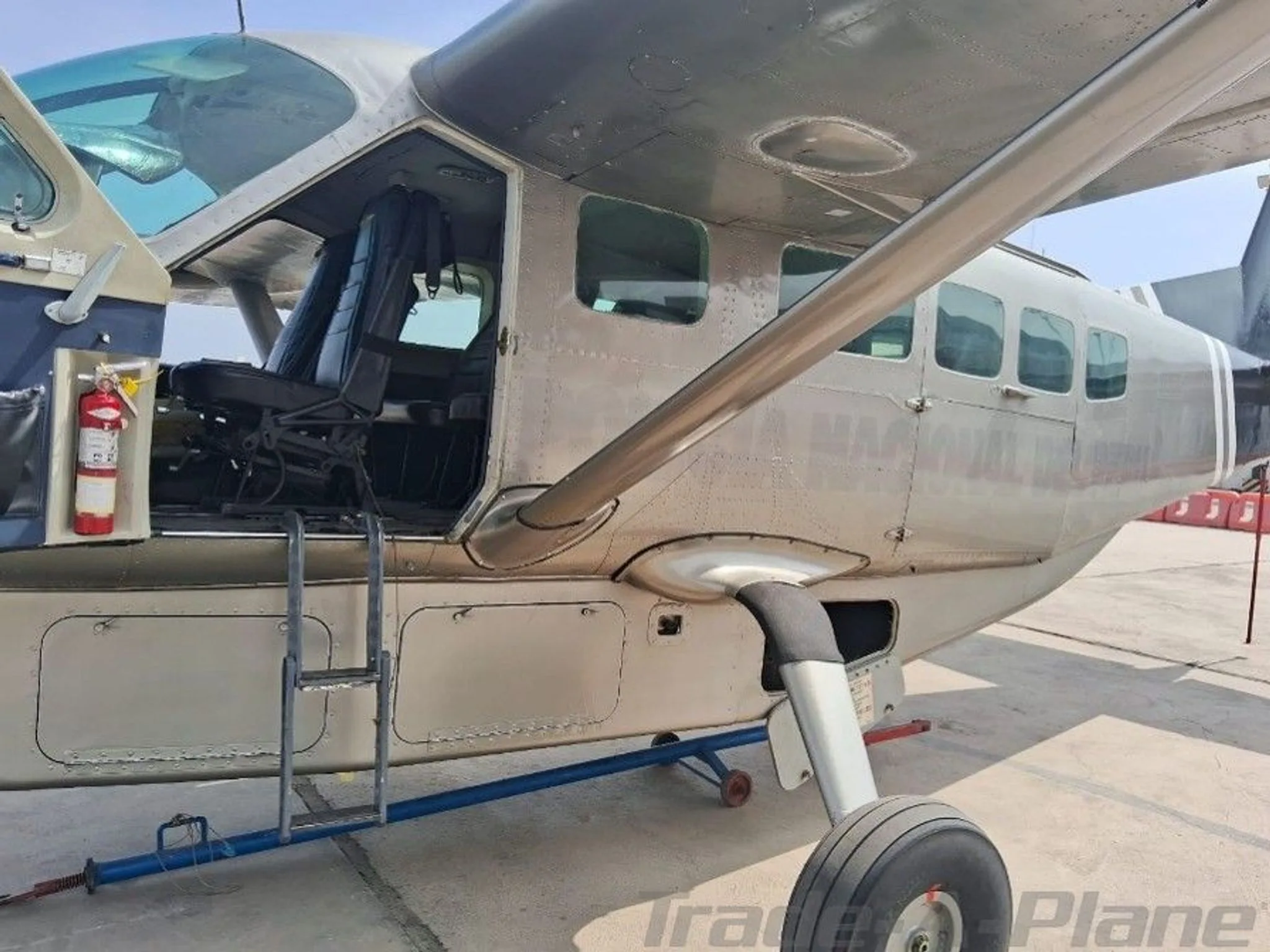
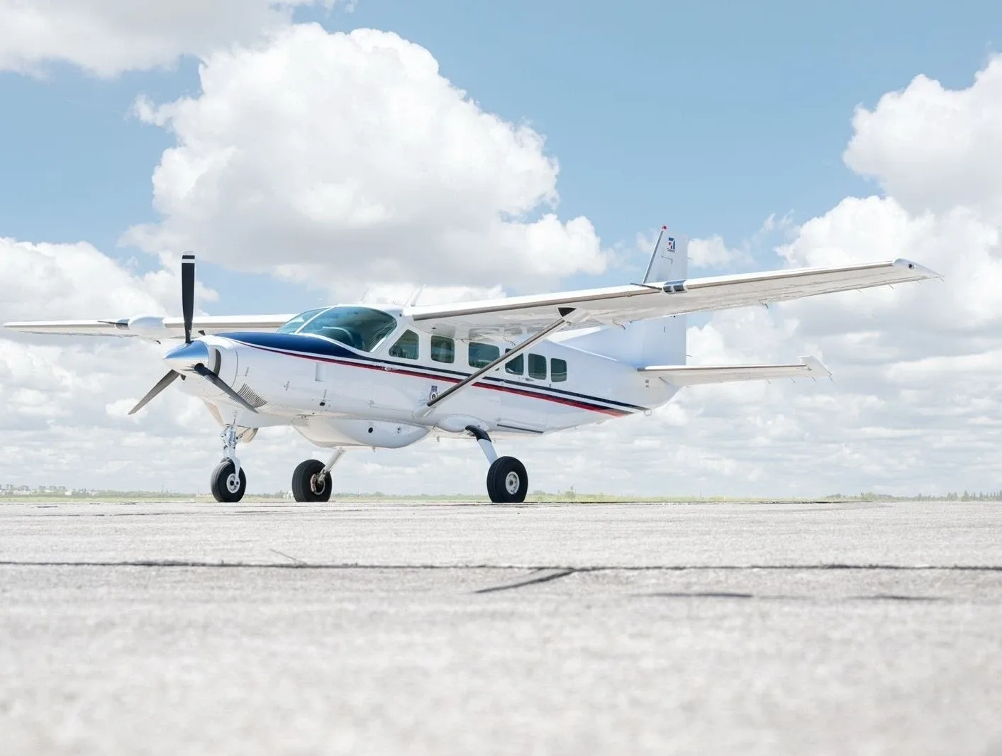
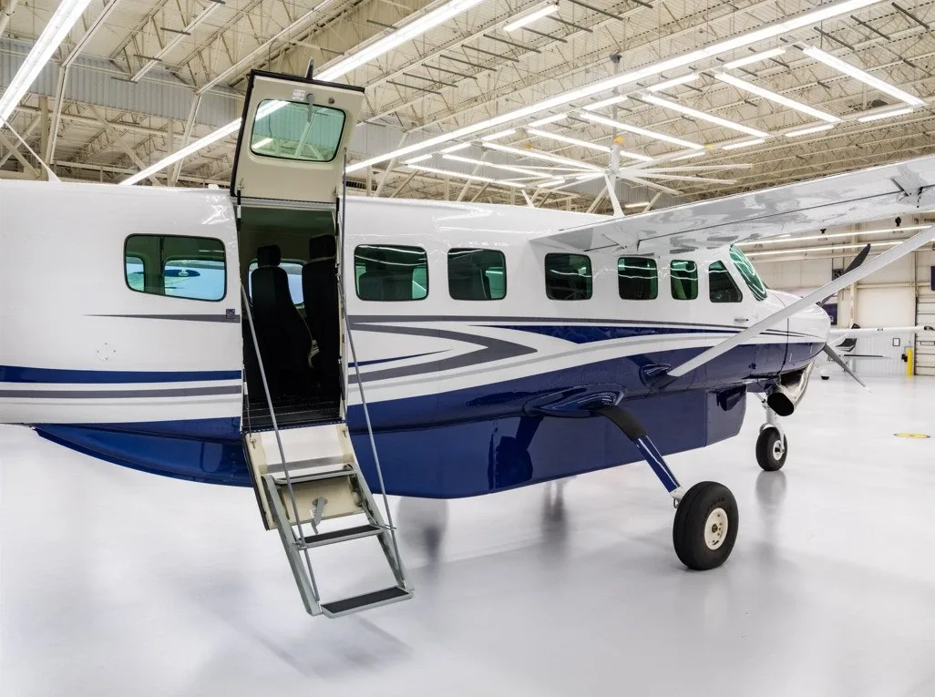
Free — save the 208 to your watchlist and track it in one place.
More CESSNA CARAVAN 208manuals & documents
Related documents
- CESSNA MODEL 208B G1000Cessna 208B Grand Caravan · Pilot's Operating Handbook
- Cessna 208B/TPE331-12JR Landplane Airplane Flight Manual SupplementCESSNA CARAVAN 208B GRAND AMPHIBIAN · Flight Manual
- CESSNA MODEL 172S NAV III GFC 700 AFCSCESSNA 172S SKYHAWK SP · Training Manual
- Normal Procedures for the Cessna 152 AerobatCessna 152 Aerobat · Normal Procedures
- IM-Cessna-Stationair-U206G-1981.pdf - Club AereoCESSNA U206F STATIONAIR · Pilot's Operating Handbook
If you fly the CESSNA CARAVAN 208, you may also be researching these.


In this document
Introduction
The introduction outlines the purpose of the Pilot's Operating Handbook (POH) and its importance for the operation of the Cessna 208B.
Performance Specifications
Details the performance capabilities of the Cessna 208B, including maximum cruise speeds and weights.
Fuel Specifications
Lists approved fuel grades and the requirement for fuel additives in freezing temperatures.
Warnings, Cautions, and Notes
Highlights important operational procedures and maintenance practices to ensure safety.
Log of Effective Pages
Provides a method for tracking the currency and applicability of the manual's content.
Weight and Balance Terminology
Defines key terms related to weight and balance for proper aircraft loading and operation.
Summary written by AI from the source document. Check the original before relying on it. See which parts of Sprinkle are written by AI.
Safety notes
- Use of unapproved fuels may result in engine damage.
- A thorough understanding of autopilot systems is required before operation.
- Warnings are provided for procedures that may result in personal injury.
- Fuel anti-ice additives are required if freezing temperatures are expected.
- Maximum ramp weight must not be exceeded.
Summary written by AI from the source document. Check the original before relying on it. See which parts of Sprinkle are written by AI.
Full document text
Cessna caravan 208b maintenance manual pdf download pdf Cessna 208b poh pdf. Cessna caravan 208b training manual pdf. Cessna 208b flight manual. Cessna 208 caravan manual. Page 1 SERIAL NUMBER Model 208B 867 SHP - Garmin G1000 REGISTRATION NUMBER Serials 208B2197 and 208B5000 and On This publication includes the material required to be furnished to the pilot by 14 CFR 23. COPYRIGHT © 2012 ORIGINAL ISSUE - 19 DECEMBER 2012 CESSNA AIRCRAFT COMPANY WICHITA, KANSAS, USA REVISION 1 - 22 MAY 2013... Page 3 CESSNA INTRODUCTION MODEL 208B (867 SHP) GARMIN G1000 PILOT’S OPERATING HANDBOOK FAA APPROVED AIRPLANE FLIGHT MANUAL CESSNA MODEL 208B (867 SHP) GARMIN G1000 SERIALS 208B2197 AND 208B5000 AND ON ORIGINAL ISSUE - 19 DECEMBER 2012 REVISION 1 - 22 MAY 2013 PART NUMBER: 208BPHCUS-01 208BPHCUS-01 U.S. Page 4 INTRODUCTION CESSNA MODEL 208B (867 SHP) GARMIN G1000 This Page Intentionally Left Blank U.S. 208BPHCUS-00... Page 5 CESSNA INTRODUCTION MODEL 208B (867 SHP) GARMIN G1000 CONGRATULATIONS Congratulations on your purchase and welcome to Cessna ownership! Your Cessna has been designed and constructed to give you the most in performance, value and comfort. This Pilot’s Operating Handbook has been prepared as a guide to help you get the most utility from your airplane. Page 6 INTRODUCTION CESSNA MODEL 208B (867 SHP) GARMIN G1000 PERFORMANCE - SPECIFICATIONS CARGO VERSION SPEED (KTAS): Maximum Cruise at 10,000 Feet ....185 KNOTS Maximum Cruise at 20,000 Feet . Page 7 CESSNA INTRODUCTION MODEL 208B (867 SHP) GARMIN G1000 PERFORMANCE - SPECIFICATIONS CARGO VERSION (Continued) MAXIMUM WEIGHT: Ramp......8842 POUNDS (4010.7 kg) Takeoff . Page 8 INTRODUCTION CESSNA MODEL 208B (867 SHP) GARMIN G1000 PERFORMANCE - SPECIFICATIONS PASSENGER VERSION SPEED (KTAS): Maximum Cruise at 10,000 Feet ....195 KNOTS Maximum Cruise at 20,000 Feet . Page 9 CESSNA INTRODUCTION MODEL 208B (867 SHP) GARMIN G1000 PERFORMANCE - SPECIFICATIONS PASSENGER VERSION (Continued) MAXIMUM WEIGHT: Ramp......8842 POUNDS (4010.7 kg) Takeoff . Page 10 INTRODUCTION CESSNA MODEL 208B (867 SHP) GARMIN G1000 COVERAGE The Pilot’s Operating Handbook (POH) in the airplane at the time of delivery from Cessna Aircraft Company contains information applicable to the Model 208B (867 SHP) airplanes by serial number and registration number shown on the Title Page. Page 11 CESSNA INTRODUCTION MODEL 208B (867 SHP) GARMIN G1000 ORIGINAL ISSUE AND REVISIONS This Pilot’s Operating Handbook and FAA Approved Airplane Flight Manual is comprised of the original issue and any subsequent revisions. To make sure that information in this manual is current, the revisions must be incorporated as they are issued. Page 12 INTRODUCTION CESSNA MODEL 208B (867 SHP) GARMIN G1000 REVISION FILING INSTRUCTIONS REGULAR REVISIONS Pages to be removed or inserted in the Pilots’ Operating Handbook and FAA Approved Airplane Flight Manual (POH/AFM) are determined by the Log of Effective Pages located in this section. This log contains the page number and revision level for each page within the POH/AFM. Page 13 CESSNA INTRODUCTION MODEL 208B (867 SHP) GARMIN G1000 IDENTIFYING REVISED MATERIAL A bar will extend the full length of deleted, new, or revised text added on new or previously existing pages. This bar will be located adjacent to the applicable text in the margin on the left side of the page. A bar in the footer will indicate a revision to the header/footer, a new page, format or spelling/grammar changes and/or that information has moved to or from that page. Page 14 INTRODUCTION CESSNA MODEL 208B (867 SHP) GARMIN G1000 WARNINGS, CAUTIONS AND NOTES Throughout the text, warnings, cautions and notes pertaining to airplane handling and operations are utilized. These adjuncts to the text are used to highlight or emphasize important points. WARNING An operating procedure, technique, or maintenance practice which may result in personal injury or loss... Page 15 CESSNA INTRODUCTION MODEL 208B (867 SHP) GARMIN G1000 LOG OF EFFECTIVE PAGES Use this page to determine the currency and applicability of your POH/ AFM. Pages affected by the current revision are indicated by an asterisk (*) preceding the pages listed under the Page Number column. Revision Level Date of Issue Revision Level... Page 16 INTRODUCTION CESSNA MODEL 208B (867 SHP) GARMIN G1000 LOG OF EFFECTIVE PAGES (Continued) Page Page Revision Number Status Number * 2-27 Revised 2-28 thru 2-31 Original * 2-32 Revised 2-33 thru 2-62 Original 3-1 thru 3-32 Original * 3-33 Revised 3-34 thru 3-66 Original * 3-67 thru 3-69... Page 17 CESSNA INTRODUCTION MODEL 208B (867 SHP) GARMIN G1000 LOG OF EFFECTIVE PAGES (Continued) Page Page Revision Number Status Number 7-60 Original * 7-61 Revised 7-62 thru 7-75 Original * 7-76 thru 7-78 Revised 7-79 thru 7-126 Original 8-1 thru 8-16 Original * 8-17 thru 8-18 Revised... Page 18 INTRODUCTION CESSNA MODEL 208B (867 SHP) GARMIN G1000 This Page Intentionally Left Blank U.S. 208BPHCUS-01... Page 19 CESSNA INTRODUCTION MODEL 208B (867 SHP) GARMIN G1000 SERVICE BULLETIN CONFIGURATION LIST The following is a list of Service Bulletins that are applicable to the operation of the airplane, and have been incorporated into this manual. This list contains only those Service Bulletins that are currently active. Number Title Airplane Serial... Page 20 INTRODUCTION CESSNA MODEL 208B (867 SHP) GARMIN G1000 This Page Intentionally Left Blank xviii U.S. 208BPHCUS-01... Page 21 CESSNA INTRODUCTION MODEL 208B (867 SHP) GARMIN G1000 TABLE OF CONTENTS SECTION GENERAL ........1 LIMITATIONS . Page 22 INTRODUCTION CESSNA MODEL 208B (867 SHP) GARMIN G1000 This Page Intentionally Left Blank U.S. 208BPHCUS-01... CESSNA SECTION 1 MODEL 208B (867 SHP) GENERAL GARMIN G1000 GENERAL TABLE OF CONTENTS Page Three View - Normal Ground Attitude ......1-3 Introduction . Page 24 SECTION 1 CESSNA GENERAL MODEL 208B (867 SHP)
Show full textShow less
GARMIN G1000 This Page Intentionally Left Blank 208BPHCUS-00 U.S. CESSNA SECTION 1 MODEL 208B (867 SHP) GENERAL GARMIN G1000 THREE VIEW - NORMAL GROUND ATTITUDE Figure 1-1 (Sheet 1 of 2) 208BPHCUS-00 U.S. Page 26 SECTION 1 CESSNA GENERAL MODEL 208B (867 SHP) GARMIN G1000 THREE VIEW - NORMAL GROUND ATTITUDE NOTE • Normal ground attitude shown is based on standard empty weight, proper inflation of nosewheel and main gear tires and wings level. • Wing span shown with position/strobe lights installed. CESSNA SECTION 1 MODEL 208B (867 SHP) GENERAL GARMIN G1000 INTRODUCTION This POH/AFM contains 9 sections, and includes the material required to be furnished to the pilot by 14 CFR 23. It also contains supplemental data supplied by Cessna Aircraft Company. This POH/AFM constitutes the FAA Approved Airplane Flight Manual. SECTION 1 CESSNA GENERAL MODEL 208B (867 SHP) GARMIN G1000 DESCRIPTIVE DATA ENGINE Number of Engines ........1 Engine Manufacturer . CESSNA SECTION 1 MODEL 208B (867 SHP) GENERAL GARMIN G1000 DESCRIPTIVE DATA (Continued) FUEL WARNING USE OF UNAPPROVED FUELS MAY RESULT IN DAMAGE TO THE ENGINE AND FUEL SYSTEM COMPONENTS, RESULTING IN POSSIBLE ENGINE FAILURE. APPROVED FUEL GRADES: JET A (ASTM-D1655) JP-8+100 (MIL-DTL-83133) JET A-1 (ASTM-D1655) AN8 (MIL-DTL-83133) Page 30 SECTION 1 CESSNA GENERAL MODEL 208B (867 SHP) GARMIN G1000 DESCRIPTIVE DATA (Continued) FUEL (Continued) APPROVED FUEL ADDITIVES One of the following fuel system anti-ice additives must be added to the fuel as noted at the following concentrations. Use of fuel anti-ice additives is required if freezing temperatures are expect during any part of the flight. Page 31 CESSNA SECTION 1 MODEL 208B (867 SHP) GENERAL GARMIN G1000 DESCRIPTIVE DATA (Continued) FUEL (Continued) FUEL CAPACITY TOTAL FUEL Both Tanks and Reservoir: ...339.1 U.S. Gallons (1283 l) Both Tanks: ..... .335.6 U.S. Gallons (1270 l) Each Tank: . SECTION 1 CESSNA GENERAL MODEL 208B (867 SHP) GARMIN G1000 DESCRIPTIVE DATA (Continued) OIL SPECIFICATION Oil conforming to Pratt & Whitney Engine Service Bulletin No. 1001, and all revisions or supplements thereto, must be used. Refer to Section 8, Airplane Handling, Service and Maintenance, Servicing, Oil, for a listing of approved oils. CESSNA SECTION 1 MODEL 208B (867 SHP) GENERAL GARMIN G1000 DESCRIPTIVE DATA (Continued) MAXIMUM CERTIFICATED WEIGHTS Ramp Weight ......8842 POUNDS (4010 kg) Takeoff Weight . SECTION 1 CESSNA GENERAL MODEL 208B (867 SHP) GARMIN G1000 SYMBOLS, ABBREVIATIONS AND TERMINOLOGY GENERAL AIRSPEED TERMINOLOGY AND SYMBOLS KCAS Knots Calibrated Airspeed is indicated airspeed corrected for position and instrument error and expressed in knots. Knots calibrated airspeed is equal to KTAS in standard atmosphere at sea level. CESSNA SECTION 1 MODEL 208B (867 SHP) GENERAL GARMIN G1000 SYMBOLS, ABBREVIATIONS AND TERMINOLOGY (Continued) METEOROLOGICAL TERMINOLOGY Outside Air Temperature is the free air static temperature. It may be expressed in either degrees Celsius (°C) or degrees Fahrenheit (°F). International Standard Atmosphere is an atmosphere in which: 1. Page 36 SECTION 1 CESSNA GENERAL MODEL 208B (867 SHP) GARMIN G1000 SYMBOLS, ABBREVIATIONS AND TERMINOLOGY (Continued) ENGINE POWER TERMINOLOGY (Continued) Hot Start Hot Start is an engine start, or attempted start, which results in an ITT exceeding 1090°C. Interstage Turbine Temperature Maximum Maximum Climb Power is the maximum power Climb Power... CESSNA SECTION 1 MODEL 208B (867 SHP) GENERAL GARMIN G1000 SYMBOLS, ABBREVIATIONS AND TERMINOLOGY (Continued) AIRPLANE PERFORMANCE AND FLIGHT PLANNING TERMINOLOGY Demonstrated Demonstrated Crosswind Velocity is the velocity of Crosswind the crosswind component for which adequate control Velocity of the airplane during takeoff and landing was actually demonstrated during certification tests. SECTION 1 CESSNA GENERAL MODEL 208B (867 SHP) GARMIN G1000 SYMBOLS, ABBREVIATIONS AND TERMINOLOGY (Continued) AUTOPILOT/FLIGHT DIRECTOR AFCS TERMINOLOGY CAUTION A thorough understanding of the difference between an autopilot, a flight director, and an AFCS is required before operating any of the components of the Garmin G1000/GFC 700 Flight Control System. CESSNA SECTION 1 MODEL 208B (867 SHP) GENERAL GARMIN G1000 SYMBOLS, ABBREVIATIONS AND TERMINOLOGY (Continued) WEIGHT AND BALANCE TERMINOLOGY Reference Reference Datum is an imaginary vertical plane from Datum which all horizontal distances are measured for balance purposes. Station Station is a location along the airplane fuselage given in terms of the distance from the reference datum. Page 40 SECTION 1 CESSNA GENERAL MODEL 208B (867 SHP) GARMIN G1000 SYMBOLS, ABBREVIATIONS AND TERMINOLOGY (Continued) WEIGHT AND BALANCE TERMINOLOGY (Continued) Mean Aerodynamic Chord is a chord of an imaginary rectangular airfoil having the same pitching moments throughout the flight range as that of the actual wing. Maximum Maximum Ramp Weight is the maximum weight Ramp Weight... CESSNA SECTION 1 MODEL 208B (867 SHP) GENERAL GARMIN G1000 METRIC/IMPERIAL/U.S. CONVERSION CHARTS The following charts have been provided to help international operators convert U.S. measurement supplied with the POH/AFM into metric and imperial measurements. The standard followed for measurement units shown is the National Institute of Standards Technology (NIST), Publication 811, "Guide for the Use of the International System of Units (SI)."... SECTION 1 CESSNA GENERAL MODEL 208B (867 SHP) GARMIN G1000 WEIGHT CONVERSIONS Figure 1-2 (Sheet 1 of 2) 208BPHCUS-00 1-20 U.S. Page 43 CESSNA SECTION 1 MODEL 208B (867 SHP) GENERAL GARMIN G1000 WEIGHT CONVERSIONS Figure 1-2 (Sheet 2) 208BPHCUS-00 1-21 U.S. SECTION 1 CESSNA GENERAL MODEL 208B (867 SHP) GARMIN G1000 LENGTH CONVERSIONS Figure 1-3 (Sheet 1 of 4) 208BPHCUS-00 1-22 U.S. Page 45 CESSNA SECTION 1 MODEL 208B (867 SHP) GENERAL GARMIN G1000 LENGTH CONVERSIONS Figure 1-3 (Sheet 2) 208BPHCUS-00 1-23 U.S. Page 46 SECTION 1 CESSNA GENERAL MODEL 208B (867 SHP) GARMIN G1000 LENGTH CONVERSIONS Figure 1-3 (Sheet 3) 208BPHCUS-00 1-24 U.S. Page 47 CESSNA SECTION 1 MODEL 208B (867 SHP) GENERAL GARMIN G1000 LENGTH CONVERSIONS Figure 1-3 (Sheet 4) 208BPHCUS-00 1-25 U.S. SECTION 1 CESSNA GENERAL MODEL 208B (867 SHP) GARMIN G1000 DISTANCE CONVERSIONS Figure 1-4 208BPHCUS-00 1-26 U.S. CESSNA SECTION 1 MODEL 208B (867 SHP) GENERAL GARMIN G1000 VOLUME CONVERSIONS Figure 1-5 (Sheet 1 of 3) 208BPHCUS-00 1-27 U.S. Page 50 SECTION 1 CESSNA GENERAL MODEL 208B (867 SHP) GARMIN G1000 VOLUME CONVERSIONS Figure 1-5 (Sheet 2) 208BPHCUS-00 1-28 U.S. Page 51 CESSNA SECTION 1 MODEL 208B (867 SHP) GENERAL GARMIN G1000 VOLUME CONVERSIONS Figure 1-5 (Sheet 3) 208BPHCUS-00 1-29 U.S. SECTION 1 CESSNA GENERAL MODEL 208B (867 SHP) GARMIN G1000 TEMPERATURE CONVERSIONS Figure 1-6 208BPHCUS-00 1-30 U.S. CESSNA SECTION 1 MODEL 208B (867 SHP) GENERAL GARMIN G1000 PRESSURE CONVERSION HECTOPASCALS TO INCHES OF MERCURY Figure 1-7 208BPHCUS-00 1-31 U.S. Page 54 SECTION 1 CESSNA GENERAL MODEL 208B (867 SHP) GARMIN G1000 This Page Intentionally Left Blank 208BPHCUS-00 1-32 U.S. Page 55 CESSNA SECTION 2 MODEL 208B (867 SHP) OPERATING LIMITATIONS GARMIN G1000 OPERATING LIMITATIONS TABLE OF CONTENTS Page Introduction ..........2-3 Airspeed Limitations . Page 56 SECTION 2 CESSNA OPERATING LIMITATIONS MODEL 208B (867 SHP) GARMIN G1000 TABLE OF CONTENTS (Continued) Page Other Limitations ........2-37 Optional Equipment User’s Guide . CESSNA SECTION 2 MODEL 208B (867 SHP) OPERATING LIMITATIONS GARMIN G1000 INTRODUCTION Section 2 includes operating limitations, instrument markings, and basic placards necessary for the safe operation of the airplane, its engine, standard/non-standard systems and standard/non-standard equipment. WARNING The limitations included in this section and in Section 9 have been approved by the Federal Aviation Administration. SECTION 2 CESSNA OPERATING LIMITATIONS MODEL 208B (867 SHP) GARMIN G1000 AIRSPEED LIMITATIONS The airspeed limitations below are based on the maximum gross takeoff weight of 8807 pounds (3994 kg). The maximum operating maneuvering speeds (V ) and applicable gross weight limitations are shown in Figure 2-1. CESSNA SECTION 2 MODEL 208B (867 SHP) OPERATING LIMITATIONS GARMIN G1000 AIRSPEED INDICATOR MARKINGS The airspeed on both the PFD and standby airspeed indicator is indicated with an airspeed tape with colored bands, refer to Section 7, Flight Instruments, for more information on airspeed indication. The indicator markings and their color code significance are shown in Figure 2-2. SECTION 2 CESSNA OPERATING LIMITATIONS MODEL 208B (867 SHP) GARMIN G1000 POWERPLANT LIMITATIONS ENGINE Engine Manufacturer ....Pratt & Whitney Canada Inc. Engine Model Number ......PT6A-140 Engine Operating Limits . Page 61 CESSNA SECTION 2 MODEL 208B (867 SHP) OPERATING LIMITATIONS GARMIN G1000 POWERPLANT LIMITATIONS (Continued) PROPELLER SYSTEM OPERATING LIMITS An overspeed governor check shall be performed before the first flight of the day, after engine control system maintenance, or if adjustment has been made. Propeller RPM must be set at 1900 during all instrument approaches. Page 62 SECTION 2 CESSNA OPERATING LIMITATIONS MODEL 208B (867 SHP) GARMIN G1000 POWERPLANT LIMITATIONS (Continued) ENGINE OPERATING LIMITS Figure 2-3 (Sheet 1 of 2) FAA APPROVED 208BPHCUS-00 U.S. Page 63 CESSNA SECTION 2 MODEL 208B (867 SHP) OPERATING LIMITATIONS GARMIN G1000 POWER PLANT LIMITATIONS (Continued) ENGINE OPERATING LIMITS (Continued) NOTE 1. Per Section 5, Performance, Figure 5-8, Maximum Engine Torque for Takeoff. Anytime ITT exceeds 825°C, this power setting is limited to 5 minutes. 2. SECTION 2 CESSNA OPERATING LIMITATIONS MODEL 208B (867 SHP) GARMIN G1000 POWERPLANT INSTRUMENT MARKINGS Powerplant instrument markings and their color code significance are shown in Figure 2-3. Operation with indications in the red range is prohibited. Avoid operating with indicators in the yellow range. NOTE 1. CESSNA SECTION 2 MODEL 208B (867 SHP) OPERATING LIMITATIONS GARMIN G1000 MISCELLANEOUS INSTRUMENT MARKINGS Power plant instrument markings and their color significance are shown in Figure 2-5. NOTE 1. OFF mode is defined as anytime the engine is not running and the starter has not transitioned to generator mode. SECTION 2 CESSNA OPERATING LIMITATIONS MODEL 208B (867 SHP) GARMIN G1000 PREFLIGHT Takeoff is prohibited with any frost, ice, snow, or slush adhering to the wings, horizontal stabilizer, vertical stabilizer, control surfaces, propeller blades, and/or engine air inlets. WARNING Even small amounts of frost, ice, snow or slush on the wing may adversely change lift and drag. CESSNA SECTION 2 MODEL 208B (867 SHP) OPERATING LIMITATIONS GARMIN G1000 WEIGHT LIMITS Maximum Ramp Weight ....8842 Pounds (4010 kg) Maximum Takeoff Weight ....8807 Pounds (3994 kg) Maximum Landing Weight. SECTION 2 CESSNA OPERATING LIMITATIONS MODEL 208B (867 SHP) GARMIN G1000 MANEUVER LIMITS This airplane is certificated in the normal category. The normal category is applicable to aircraft intended for non-aerobatic operations. These include any maneuvers incidental to normal flying, stalls (except whip stalls), lazy eights, chandelles, and turns in which the angle of bank is not more than 60°. CESSNA SECTION 2 MODEL 208B (867 SHP) OPERATING LIMITATIONS GARMIN G1000 KINDS OF OPERATIONS LIMITS The Cessna 208B (867 SHP) equipped with the Garmin G1000 is approved for day and night, VFR and IFR operations. The airplane may be approved for flight into known icing conditions when appropriate equipment is installed. SECTION 2 CESSNA OPERATING LIMITATIONS MODEL 208B (867 SHP) GARMIN G1000 KINDS OF OPERATIONS EQUIPMENT LIST (Continued Next Page) FAA APPROVED 208BPHCUS-01 2-16 U.S. Page 71 CESSNA SECTION 2 MODEL 208B (867 SHP) OPERATING LIMITATIONS GARMIN G1000 KINDS OF OPERATIONS EQUIPMENT LIST (Continued) (Continued Next Page) FAA APPROVED 208BPHCUS-01 2-17 U.S. Page 72 SECTION 2 CESSNA OPERATING LIMITATIONS MODEL 208B (867 SHP) GARMIN G1000 KINDS OF OPERATIONS EQUIPMENT LIST (Continued) (Continued Next Page) FAA APPROVED 208BPHCUS-01 2-18 U.S. Page 73 CESSNA SECTION 2 MODEL 208B (867 SHP) OPERATING LIMITATIONS GARMIN G1000 KINDS OF OPERATIONS EQUIPMENT LIST (Continued) (Continued Next Page) FAA APPROVED 208BPHCUS-01 2-19 U.S. Page 74 SECTION 2 CESSNA OPERATING LIMITATIONS MODEL 208B (867 SHP) GARMIN G1000 KINDS OF OPERATIONS EQUIPMENT LIST (Continued) (Continued Next Page) FAA APPROVED 208BPHCUS-01 2-20 U.S. Page 75 CESSNA SECTION 2 MODEL 208B (867 SHP) OPERATING LIMITATIONS GARMIN G1000 KINDS OF OPERATIONS EQUIPMENT LIST (Continued) (Continued Next Page) FAA APPROVED 208BPHCUS-01 2-21 U.S. Page 76 SECTION 2 CESSNA OPERATING LIMITATIONS MODEL 208B (867 SHP) GARMIN G1000 KINDS OF OPERATIONS EQUIPMENT LIST (Continued) (Continued Next Page) FAA APPROVED 208BPHCUS-01 2-22 U.S. Page 77 CESSNA SECTION 2 MODEL 208B (867 SHP) OPERATING LIMITATIONS GARMIN G1000 KINDS OF OPERATIONS EQUIPMENT LIST (Continued) (Continued Next Page) FAA APPROVED 208BPHCUS-01 2-23 U.S. Page 78 SECTION 2 CESSNA OPERATING LIMITATIONS MODEL 208B (867 SHP) GARMIN G1000 KINDS OF OPERATIONS EQUIPMENT LIST (Continued) FAA APPROVED 208BPHCUS-01 2-24 U.S. CESSNA SECTION 2 MODEL 208B (867 SHP) OPERATING LIMITATIONS GARMIN G1000 FUEL LIMITATIONS FUEL CAPACITY TOTAL FUEL Both Tanks and Reservoir: ...339.1 U.S. Gallons (1283 l) Both Tanks: ..... .335.6 U.S. Gallons (1270 l) Each Tank: . Page 80 SECTION 2 CESSNA OPERATING LIMITATIONS MODEL 208B (867 SHP) GARMIN G1000 FUEL LIMITATIONS FUEL GRADE (SPECIFICATION) AND FUEL ADDITIVES * It is assumed that fuel temperature is the same as Outside Air Temperature (OAT). ** AN8 is JP-8 fuel with a reduced freeze point specified for Antarctic operations. Page 81 CESSNA SECTION 2 MODEL 208B (867 SHP) OPERATING LIMITATIONS GARMIN G1000 FUEL LIMITATIONS (Continued) FUEL GRADE (SPECIFICATION) AND FUEL ADDITIVES (Continued) APPROVED FUEL ADDITIVES One of the following fuel system anti-ice additives must be added to the fuel as noted at the following concentrations. Use of fuel anti-ice additives is required if freezing temperatures are expected during any part of the flight. SECTION 2 CESSNA OPERATING LIMITATIONS MODEL 208B (867 SHP) GARMIN G1000 MAXIMUM OPERATING ALTITUDE LIMIT Non-Icing Conditions ......25,000 Feet Icing Conditions (if equipped) . CESSNA SECTION 2 MODEL 208B (867 SHP) OPERATING LIMITATIONS GARMIN G1000 SYSTEM AND EQUIPMENT LIMITATIONS FLAP LIMITATIONS Approved Takeoff Range..... . .UP to TO/APR Approved Landing Range . SECTION 2 CESSNA OPERATING LIMITATIONS MODEL 208B (867 SHP) GARMIN G1000 SYSTEM AND EQUIPMENT LIMITATIONS (Continued) GENERATOR LIMITATIONS Maximum generator load limit is a function of Ng, air conditioning and bleed air heat position. ON GROUND MAXIMUM GENERATOR LOAD - GROUND OPERATIONS AIR CONDITIONING - OFF, AIR CONDITIONING - ON, BLEED AIR HEAT - ON or OFF... CESSNA SECTION 2 MODEL 208B (867 SHP) OPERATING LIMITATIONS GARMIN G1000 SYSTEM AND EQUIPMENT LIMITATIONS (Continued) G1000 LIMITATIONS The current Garmin G1000 Cockpit Reference Guide (CRG) Part Number and System Software Version that must be available to the pilot during flight are displayed on the MFD AUX group, SYSTEM STATUS page. Page 86 SECTION 2 CESSNA OPERATING LIMITATIONS MODEL 208B (867 SHP) GARMIN G1000 SYSTEM AND EQUIPMENT LIMITATIONS (Continued) G1000 LIMITATIONS (Continued) Use of the TERRAIN PROXIMITY information for primary terrain avoidance is prohibited. The Terrain Proximity map is intended only to enhance situational awareness. It is the pilot’s responsibility to provide terrain clearance at all times. CESSNA SECTION 2 MODEL 208B (867 SHP) OPERATING LIMITATIONS GARMIN G1000 SYSTEM AND EQUIPMENT LIMITATIONS (Continued) G1000 LIMITATIONS (Continued) OPERATIONAL APPROVALS The Garmin G1000 GPS receivers are approved under TSO C145c Class 3. The Garmin G1000 system has been demonstrated capable of, and has been shown to meet the accuracy requirements for, the following operations provided it is receiving usable navigation data. SECTION 2 CESSNA OPERATING LIMITATIONS MODEL 208B (867 SHP) GARMIN G1000 SYSTEM AND EQUIPMENT LIMITATIONS (Continued) G1000 LIMITATIONS (Continued) GARMIN GFC 700 AUTOMATED FLIGHT CONTROL SYSTEM (AFCS) 1. The GFC 700 AFCS preflight test must be successfully completed prior to use of the autopilot, flight director or manual electric trim. CESSNA SECTION 2 MODEL 208B (867 SHP) OPERATING LIMITATIONS GARMIN G1000 SYSTEM AND EQUIPMENT LIMITATIONS (Continued) G1000 LIMITATIONS (Continued) L3 COMMUNICATIONS WX 500 STORMSCOPE (if installed) Use of the WEATHER MAP (WX-500 Stormscope) for hazardous weather (thunderstorm) penetration is prohibited. LTNG information on the NAVIGATION MAP or WEATHER MAP is approved only as an aid to hazardous weather avoidance, not penetration. SECTION 2 CESSNA OPERATING LIMITATIONS MODEL 208B (867 SHP) GARMIN G1000 SYSTEM AND EQUIPMENT LIMITATIONS (Continued) G1000 LIMITATIONS (Continued) TERRAIN AWARENESS AND WARNING SYSTEM (TAWS-B) (if installed) Use of the Terrain Awareness and Warning System (TAWS-B) to navigate to avoid terrain or obstacles is prohibited. TAWS-B is only approved as an aid to help the pilot to see-and-avoid terrain or obstacles. CESSNA SECTION 2 MODEL 208B (867 SHP) OPERATING LIMITATIONS GARMIN G1000 OTHER LIMITATIONS OPTIONAL EQUIPMENT USER’S GUIDE The pilot is responsible for ensuring the appropriate user’s guide(s) for all optional equipment installed in the airplane is accessible to the pilot in flight. SECTION 2 CESSNA OPERATING LIMITATIONS MODEL 208B (867 SHP) GARMIN G1000 OTHER LIMITATIONS (Continued) FLIGHT IN KNOWN ICING VISUAL CUES As Required by AD 96-09-15, Paragraph (a) (1) WARNING Severe icing may result from environmental conditions outside of those for which the airplane is certificated. CESSNA SECTION 2 MODEL 208B (867 SHP) OPERATING LIMITATIONS GARMIN G1000 PLACARDS WARNING The following information must be displayed in the form of composite or individual placards. As a minimum, the exact wording of these placards is required as specified in this section. Placard wording can be from part numbered placards obtained from... Page 94 SECTION 2 CESSNA OPERATING LIMITATIONS MODEL 208B (867 SHP) GARMIN G1000 PLACARDS (Continued) INTERIOR PLACARDS (Continued) FLIGHT CREW AREA (Continued) In full view of the pilot on the sunvisor or windshield trim: (Continued Next Page) FAA APPROVED 208BPHCUS-00 2-40 U.S. Page 95 CESSNA SECTION 2 MODEL 208B (867 SHP) OPERATING LIMITATIONS GARMIN G1000 PLACARDS (Continued) INTERIOR PLACARDS (Continued) FLIGHT CREW AREA (Continued) On overhead panel adjacent to fuel tank selectors: Located on magnetic compass: (Continued Next Page) FAA APPROVED 208BPHCUS-00 2-41 U.S. Page 96 SECTION 2 CESSNA OPERATING LIMITATIONS MODEL 208B (867 SHP) GARMIN G1000 PLACARDS (Continued) INTERIOR PLACARDS (Continued) FLIGHT CREW AREA (Continued) Above left side PFD: On instrument panel below standby instruments: (Continued Next Page) FAA APPROVED 208BPHCUS-00 2-42 U.S. Page 97 CESSNA SECTION 2 MODEL 208B (867 SHP) OPERATING LIMITATIONS GARMIN G1000 PLACARDS (Continued) INTERIOR PLACARDS (Continued) FLIGHT CREW AREA (Continued) On pedestal adjacent to wing flap position indicator: On pedestal below the power lever: (Continued Next Page) FAA APPROVED 208BPHCUS-00 2-43 U.S. Page 98 SECTION 2 CESSNA OPERATING LIMITATIONS MODEL 208B (867 SHP) GARMIN G1000 PLACARDS (Continued) INTERIOR PLACARDS (Continued) FLIGHT CREW AREA (Continued) On left and right lower sidewall below and forward of instrument panel: On the control lock: (Continued Next Page) FAA APPROVED 208BPHCUS-00 2-44 U.S. Page 99 CESSNA SECTION 2 MODEL 208B (867 SHP) OPERATING LIMITATIONS GARMIN G1000 PLACARDS (Continued) INTERIOR PLACARDS (Continued) FLIGHT CREW AREA (Continued) Adjacent to left crew door inside door handle: (Continued Next Page) FAA APPROVED 208BPHCUS-00 2-45 U.S. SECTION 2 CESSNA OPERATING LIMITATIONS MODEL 208B (867 SHP) GARMIN G1000 PLACARDS (Continued) INTERIOR PLACARDS (Continued) PASSENGER AREA Adjacent to upper passenger door inside door handle (Passenger version only): Adjacent to the interior door handle of lower passenger door (Passenger version only): (Continued Next Page) FAA APPROVED 208BPHCUS-00... Page 101 CESSNA SECTION 2 MODEL 208B (867 SHP) OPERATING LIMITATIONS GARMIN G1000 PLACARDS (Continued) INTERIOR PLACARDS (Continued) PASSENGER AREA (Continued) On right sidewall aft of lower passenger door below window trim (Passenger version only): Adjacent to upper cargo door interior door handle (Passenger version only): (Continued Next Page) FAA APPROVED... SECTION 2 CESSNA OPERATING LIMITATIONS MODEL 208B (867 SHP) GARMIN G1000 PLACARDS (Continued) INTERIOR PLACARDS (Continued) CARGO AREA On left and right sides of the cargo barrier (Cargo version or Passenger version when cargo barrier is installed): On right sidewall adjacent to Zone 5 (Cargo version only): (Continued Next Page) FAA APPROVED 208BPHCUS-00... Page 103 CESSNA SECTION 2 MODEL 208B (867 SHP) OPERATING LIMITATIONS GARMIN G1000 PLACARDS (Continued) INTERIOR PLACARDS (Continued) CARGO AREA (Continued) On left and right sides of cabin in appropriate zones (Cargo version only): (Continued Next Page) FAA APPROVED 208BPHCUS-00 2-49 U.S. Page 104 SECTION 2 CESSNA OPERATING LIMITATIONS MODEL 208B (867 SHP) GARMIN G1000 PLACARDS (Continued) INTERIOR PLACARDS (Continued) CARGO AREA (Continued) On inside of lower cargo door (Cargo version only) At each sidewall and ceiling anchor plate (except heavy duty anchor plates with additional structural support) and at anchor plate at center of lower cargo door (Cargo version only): (Continued Next Page) FAA APPROVED... CESSNA SECTION 2 MODEL 208B (867 SHP) OPERATING LIMITATIONS GARMIN G1000 PLACARDS (Continued) EXTERIOR PLACARDS On inside of cargo pod doors (if installed): (Continued Next Page) FAA APPROVED 208BPHCUS-00 2-51 U.S. Page 106 SECTION 2 CESSNA OPERATING LIMITATIONS MODEL 208B (867 SHP) GARMIN G1000 PLACARDS (Continued) EXTERIOR PLACARDS (Continued) Adjacent to upper cargo door outside pushbutton and door handle (Passenger version only): (Continued Next Page) FAA APPROVED 208BPHCUS-00 2-52 U.S. Page 107 CESSNA SECTION 2 MODEL 208B (867 SHP) OPERATING LIMITATIONS GARMIN G1000 PLACARDS (Continued) EXTERIOR PLACARDS (Continued) (Continued Next Page) FAA APPROVED 208BPHCUS-00 2-53 U.S. SECTION 2 CESSNA OPERATING LIMITATIONS MODEL 208B (867 SHP) GARMIN G1000 PLACARDS (Continued) EXTERIOR PLACARDS (Continued) WINGS (Continued Next Page) FAA APPROVED 208BPHCUS-00 2-54 U.S. Page 109 CESSNA SECTION 2 MODEL 208B (867 SHP) OPERATING LIMITATIONS GARMIN G1000 PLACARDS (Continued) EXTERIOR PLACARDS (Continued) WINGS (Continued) On bottom of each wing just forward of aileron: (Continued Next Page) FAA APPROVED 208BPHCUS- 00 2-55 U.S. SECTION 2 CESSNA OPERATING LIMITATIONS MODEL 208B (867 SHP) GARMIN G1000 PLACARDS (Continued) EXTERIOR PLACARDS (Continued) ENGINE COMPARTMENT On the brake fluid reservoir: (Continued Next Page) FAA APPROVED 208BPHCUS-00 2-56 U.S. Page 111 CESSNA SECTION 2 MODEL 208B (867 SHP) OPERATING LIMITATIONS GARMIN G1000 PLACARDS (Continued) EXTERIOR PLACARDS (Continued) ENGINE COMPARTMENT (Continued) Adjacent to oil dipstick/filler cap (on inertial separator duct): (Continued Next Page) FAA APPROVED 208BPHCUS-00 2-57 U.S. Page 112 SECTION 2 CESSNA OPERATING LIMITATIONS MODEL 208B (867 SHP) GARMIN G1000 PLACARDS (Continued) EXTERIOR PLACARDS (Continued) ENGINE COMPARTMENT (Continued) On firewall above battery tray: (Continued Next Page) FAA APPROVED 208BPHCUS-00 2-58 U.S. CESSNA SECTION 2 MODEL 208B (867 SHP) OPERATING LIMITATIONS GARMIN G1000 PLACARDS (Continued) EXTERIOR PLACARDS (Continued) FORWARD FUSELAGE Above ground service plug receptacle: (Continued Next Page) FAA APPROVED 208BPHCUS-00 2-59 U.S. Page 114 SECTION 2 CESSNA OPERATING LIMITATIONS MODEL 208B (867 SHP) GARMIN G1000 PLACARDS (Continued) EXTERIOR PLACARDS (Continued) FORWARD FUSELAGE (Continued) On each side of nose strut fairing near tow limit marking: (Continued Next Page) FAA APPROVED 208BPHCUS-00 2-60 U.S. CESSNA SECTION 2 MODEL 208B (867 SHP) OPERATING LIMITATIONS GARMIN G1000 PLACARDS (Continued) EXTERIOR PLACARDS (Continued) AFT FUSELAGE On the left side of the tailcone stinger, affixed to the rudder lock shaft cover plate: FAA APPROVED 208BPHCUS-00 2-61 U.S. Page 116 SECTION 2 CESSNA OPERATING LIMITATIONS MODEL 208B (867 SHP) GARMIN G1000 This Page Intentionally Left Blank FAA APPROVED 208BPHCUS-00 2-62 U.S. Page 117 CESSNA SECTION 3 MODEL 208B 867 SHP EMERGENCY PROCEDURES GARMIN G1000 EMERGENCY PROCEDURES TABLE OF CONTENTS Page Introduction ..........3-5 Airspeeds For Emergency Operation . Page 118 SECTION 3 CESSNA EMERGENCY PROCEDURES MODEL 208B 867 SHP GARMIN G1000 TABLE OF CONTENTS (Continued) Page EMERGENCY DESCENT ....... 3-23 Smooth Air . Page 119 CESSNA SECTION 3 MODEL 208B 867 SHP EMERGENCY PROCEDURES GARMIN G1000 TABLE OF CONTENTS (Continued) Page AMPLIFIED EMERGENCY PROCEDURES ....3-38 Engine Failure ........3-38 Maximum Glide . Page 120 SECTION 3 CESSNA EMERGENCY PROCEDURES MODEL 208B 867 SHP GARMIN G1000 This Page Intentionally Left Blank FAA APPROVED 208BPHCUS-00 U.S. CESSNA SECTION 3 MODEL 208B 867 SHP EMERGENCY PROCEDURES GARMIN G1000 INTRODUCTION Section 3 provides checklist and amplified procedures for coping with emergencies that may occur. Emergencies caused by airplane or engine malfunctions are extremely rare if proper preflight inspections and maintenance are practiced. SECTION 3 CESSNA EMERGENCY PROCEDURES MODEL 208B 867 SHP GARMIN G1000 AIRSPEEDS FOR EMERGENCY OPERATION ENGINE FAILURE AFTER TAKEOFF WING FLAPS Handle UP ......100 KIAS WING FLAPS Handle LAND . CESSNA SECTION 3 MODEL 208B 867 SHP EMERGENCY PROCEDURES GARMIN G1000 GENERAL OPERATING PROCEDURES - GENERAL The operating procedures contained in this manual have been developed and recommended by Cessna Aircraft Company and are approved for use in the operation of this airplane. This section contains the emergency and abnormal procedures for your airplane. Page 124 SECTION 3 CESSNA EMERGENCY PROCEDURES MODEL 208B 867 SHP GARMIN G1000 GENERAL (Continued) OPERATING PROCEDURES - GENERAL (Continued) NOTE • White annunciators provide general information, indicate the need for additional crew awareness and the possible necessity of future pilot action. •... CESSNA SECTION 3 MODEL 208B 867 SHP EMERGENCY PROCEDURES GARMIN G1000 EMERGENCY PROCEDURES Procedures in the Emergency Procedures Checklist portion of this section shown in boxes are immediate action items which should be committed to memory. ENGINE FAILURES ENGINE FAILURE DURING TAKEOFF ROLL 1. SECTION 3 CESSNA EMERGENCY PROCEDURES MODEL 208B 867 SHP GARMIN G1000 ENGINE FAILURES ENGINE FAILURE DURING FLIGHT 1. Airspeed ........95 KIAS 2. CESSNA SECTION 3 MODEL 208B 867 SHP EMERGENCY PROCEDURES GARMIN G1000 ENGINE FAILURES (Continued) ENGINE FLAMEOUT DURING FLIGHT IF GAS GENERATOR SPEED (N ) IS ABOVE 50% POWER Lever ....... . . IDLE IGNITION Switch . SECTION 3 CESSNA EMERGENCY PROCEDURES MODEL 208B 867 SHP GARMIN G1000 AIRSTART STARTER ASSIST 1. BATTERY Switch ....... . . ON 2. Page 129 CESSNA SECTION 3 MODEL 208B 867 SHP EMERGENCY PROCEDURES GARMIN G1000 AIRSTART (Continued) STARTER ASSIST (Continued) 11. FUEL BOOST Switch ......ON 12. SECTION 3 CESSNA EMERGENCY PROCEDURES MODEL 208B 867 SHP GARMIN G1000 FORCED LANDINGS EMERGENCY LANDING WITHOUT ENGINE POWER 1. Seats, Seat Belts, Shoulder Harnesses ... SECURE 2. Loose Objects ....... SECURE 3. CESSNA SECTION 3 MODEL 208B 867 SHP EMERGENCY PROCEDURES GARMIN G1000 FORCED LANDINGS (Continued) PRECAUTIONARY LANDING WITH ENGINE POWER 1. Seats, Seat Belts, Shoulder Harnesses ... SECURE 2. Loose Objects....... SECURE 3. SECTION 3 CESSNA EMERGENCY PROCEDURES MODEL 208B 867 SHP GARMIN G1000 FORCED LANDINGS (Continued) DITCHING 1. Radio ....TRANSMIT MAYDAY (on 121.5 MHz) (give location, intentions and SQUAWK 7700) 2. CESSNA SECTION 3 MODEL 208B 867 SHP EMERGENCY PROCEDURES GARMIN G1000 SMOKE AND FIRE RED ENGINE FIRE ANNUNCIATOR COMES ON DURING START ON GROUND 1. FUEL CONDITION Lever..... . CUTOFF 2. SECTION 3 CESSNA EMERGENCY PROCEDURES MODEL 208B 867 SHP GARMIN G1000 SMOKE AND FIRE (Continued) RED ENGINE FIRE ANNUNCIATOR COMES ON IN FLIGHT 1. POWER Lever........IDLE 2. CESSNA SECTION 3 MODEL 208B 867 SHP EMERGENCY PROCEDURES GARMIN G1000 SMOKE AND FIRE (Continued) ELECTRICAL FIRE IN FLIGHT 1. STBY ALT PWR Switch ......OFF 2. Page 136 SECTION 3 CESSNA EMERGENCY PROCEDURES MODEL 208B 867 SHP GARMIN G1000 SMOKE AND FIRE (Continued) ELECTRICAL FIRE IN FLIGHT (Continued) IF FIRE HAS NOT BEEN EXTINGUISHED 10. Forced Landing ......EXECUTE (refer to FORCED LANDINGS CHECKLIST) IF FIRE HAS BEEN EXTINGUISHED AND ELECTRICAL POWER IS NECESSARY FOR CONTINUED FLIGHT TO NEAREST SUITABLE... CESSNA SECTION 3 MODEL 208B 867 SHP EMERGENCY PROCEDURES GARMIN G1000 SMOKE AND FIRE (Continued) CABIN FIRE 1. STBY ALT PWR Switch ......OFF 2. SECTION 3 CESSNA EMERGENCY PROCEDURES MODEL 208B 867 SHP GARMIN G1000 SMOKE AND FIRE (Continued) WING FIRE 1. PITOT/STATIC HEAT Switch ..... . . OFF 2. CESSNA SECTION 3 MODEL 208B 867 SHP EMERGENCY PROCEDURES GARMIN G1000 EMERGENCY DESCENT SMOOTH AIR 1. Seats, Seat Belts, Shoulder Harnesses ... SECURE 2. POWER Lever ........IDLE 3. SECTION 3 CESSNA EMERGENCY PROCEDURES MODEL 208B 867 SHP GARMIN G1000 ICE AND RAIN PROTECTION THE FOLLOWING WEATHER CONDITIONS CAN BE CONDUCIVE TO SEVERE IN-FLIGHT ICING - As Required by AD 96-09-15, Paragraph (a) (2): 1. Visible rain at temperatures below 0°C (32°F) ambient air temperature. CESSNA SECTION 3 MODEL 208B 867 SHP EMERGENCY PROCEDURES GARMIN G1000 ICE AND RAIN PROTECTION (Continued) INADVERTENT ICING ENCOUNTER 1. IGNITION Switch ....... . . ON 2. Page 142 SECTION 3 CESSNA EMERGENCY PROCEDURES MODEL 208B 867 SHP GARMIN G1000 ICE AND RAIN PROTECTION (Continued) INADVERTENT ICING ENCOUNTER (Continued) 14. Plan a landing at the nearest airport. With an extremely rapid ice build-up, select a suitable off airport landing site. 15. CESSNA SECTION 3 MODEL 208B 867 SHP EMERGENCY PROCEDURES GARMIN G1000 ENGINE MALFUNCTIONS RED OIL PRESS LOW ANNUNCIATOR COMES ON 1. OIL PSI Indication......MONITOR CAUTION If oil pressure indications confirm warning annunciator, proceed in accordance with ENGINE FAILURE... SECTION 3 CESSNA EMERGENCY PROCEDURES MODEL 208B 867 SHP GARMIN G1000 FUEL SYSTEM RED RSVR FUEL LOW ANNUNCIATOR COMES ON FUEL TANK SELECTORS ....BOTH ON . CESSNA SECTION 3 MODEL 208B 867 SHP EMERGENCY PROCEDURES GARMIN G1000 FUEL SYSTEM (Continued) RED FUEL SELECT OFF ANNUNCIATOR COMES ON DURING ENGINE START AND AURAL WARNING HORNS SOUND 1. FUEL TANK SELECTORS ....BOTH ON IF RED FUEL SELECT OFF ANNUNCIATOR REMAINS ON 2. SECTION 3 CESSNA EMERGENCY PROCEDURES MODEL 208B 867 SHP GARMIN G1000 FUEL SYSTEM (Continued) RED FUEL SELECT OFF ANNUNCIATOR COMES ON PRIOR TO ENGINE START AND AURAL WARNING HORNS NOT SOUNDING 1. START CONT Circuit Breaker... . . CLOSE (push in) (top row, third breaker from forward end) 2. CESSNA SECTION 3 MODEL 208B 867 SHP EMERGENCY PROCEDURES GARMIN G1000 ELECTRICAL POWER SUPPLY SYSTEM MALFUNCTIONS RED VOLTAGE HIGH ANNUNCIATOR COMES ON 1. BUS VOLTS ....... . . CHECK If BUS VOLTS increases above 32.5, expect generator to trip offline automatically. Page 148 SECTION 3 CESSNA EMERGENCY PROCEDURES MODEL 208B 867 SHP GARMIN G1000 ELECTRICAL POWER SUPPLY SYSTEM MALFUNCTIONS (Continued) VOLTAGE HIGH ANNUNCIATOR COMES (Continued) 9. Electrical Load..... REDUCE (Continued) e. Page 149 CESSNA SECTION 3 MODEL 208B 867 SHP EMERGENCY PROCEDURES GARMIN G1000 ELECTRICAL POWER SUPPLY SYSTEM MALFUNCTIONS (Continued) VOLTAGE HIGH ANNUNCIATOR COMES (Continued) IF GENERATOR DOES NOT AUTOMATICALLY TRIP OFFLINE WITH BUS VOLTS ABOVE 32.5 2. GENERATOR Switch ......TRIP 3. SECTION 3 CESSNA EMERGENCY PROCEDURES MODEL 208B 867 SHP GARMIN G1000 ELECTRICAL POWER SUPPLY SYSTEM MALFUNCTIONS (Continued) RED VOLTAGE LOW ANNUNCIATOR COMES ON 1. BUS VOLTS ....... . . CHECK CAUTION A red VOLTAGE LOW annunciation followed by a open (tripped) BUS 1, BUS 2 or STBY PWR circuit breaker... Page 151 CESSNA SECTION 3 MODEL 208B 867 SHP EMERGENCY PROCEDURES GARMIN G1000 ELECTRICAL POWER SUPPLY SYSTEM MALFUNCTIONS (Continued) VOLTAGE ANNUNCIATOR COMES (Continued) 8. Electrical Load ....REDUCE (Continued) VENT AIR FANS . SECTION 3 CESSNA EMERGENCY PROCEDURES MODEL 208B 867 SHP GARMIN G1000 AUTOPILOT OR ELECTRIC TRIM FAILURE RED PTRM MESSAGE COMES ON 1. Control Wheel ......GRASP FIRMLY (regain control of airplane) 2. CESSNA SECTION 3 MODEL 208B 867 SHP EMERGENCY PROCEDURES GARMIN G1000 AUTOPILOT OR ELECTRIC TRIM FAILURE (Continued) RED AFCS OR YAW MESSAGE COMES ON 1. A/P CONT Circuit Breaker ....CLOSE (push in) (AVN BUS 1, second row, third breaker from left side) IF RED AFCS OR YAW MESSAGE REMAINS ON 2. SECTION 3 CESSNA EMERGENCY PROCEDURES MODEL 208B 867 SHP GARMIN G1000 AMPLIFIED EMERGENCY PROCEDURES ENGINE FAILURE If an engine failure occurs during the takeoff roll, the most important thing to do is stop the airplane on the remaining runway. Those extra items on the checklist will provide added safety after a failure of this type. Page 155 CESSNA SECTION 3 MODEL 208B 867 SHP EMERGENCY PROCEDURES GARMIN G1000 ENGINE FAILURE (Continued) A flameout can result from the engine running out of fuel, or by unstable engine operation. Unstable engine operation such as a compressor surge, possible due to a bleed valve malfunction, can be identifiable by an audible popping noise just before flameout. Page 156 SECTION 3 CESSNA EMERGENCY PROCEDURES MODEL 208B 867 SHP GARMIN G1000 ENGINE FAILURE (Continued) If an airstart is to be attempted, follow the AIRSTART checklist procedures. Successful airstarts with starter assist can be achieved at all airspeeds normally flown and up to an altitude of 14,000 feet. However, above 14,000 feet, or with the N speed below 10%, starting temperatures tend to be higher and caution is required. CESSNA SECTION 3 MODEL 208B 867 SHP EMERGENCY PROCEDURES GARMIN G1000 MAXIMUM GLIDE Figure 3-1 FAA APPROVED 208BPHCUS-00 3-41 U.S. SECTION 3 CESSNA EMERGENCY PROCEDURES MODEL 208B 867 SHP GARMIN G1000 FORCED LANDINGS If all attempts to restart the engine fail and a forced landing is imminent, select a suitable field and prepare for off-airport landing. Refer to EMERGENCY LANDING WITHOUT ENGINE POWER checklist procedures. CESSNA SECTION 3 MODEL 208B 867 SHP EMERGENCY PROCEDURES GARMIN G1000 LANDING WITHOUT ELEVATOR CONTROL Using POWER lever and ELEVATOR TRIM control, trim for approximately 500 FPM descent with WING FLAPS set to TO/APR and airspeed at 85 KIAS. Then control the glide angle by adjusting the POWER lever. Page 160 SECTION 3 CESSNA EMERGENCY PROCEDURES MODEL 208B 867 SHP GARMIN G1000 SMOKE AND FIRE (Continued) Probable causes of an engine fire are a malfunction of the fuel control unit and improper starting procedures. Improper procedures such as starting with the EMERGENCY POWER lever out of NORMAL position or introducing fuel into the engine when N is below 10% RPM will cause a hot start, which can result in an engine fire. CESSNA SECTION 3 MODEL 208B 867 SHP EMERGENCY PROCEDURES GARMIN G1000 EMERGENCY OPERATION IN CLOUDS If the vacuum pump fails in flight, the standby attitude indicator will not be accurate. The pilot must then rely on the attitude and heading information (from the AHRS) shown on the PFD indicators. SECTION 3 CESSNA EMERGENCY PROCEDURES MODEL 208B 867 SHP GARMIN G1000 EMERGENCY OPERATION IN CLOUDS (Continued) EXECUTING A 180° TURN IN CLOUDS (DUAL AHRS FAILURE) Upon inadvertently entering the clouds, an immediate turn to reverse course and return to VFR conditions should be made as follows: DUAL AHRS FAILURE 1. CESSNA SECTION 3 MODEL 208B 867 SHP EMERGENCY PROCEDURES GARMIN G1000 EMERGENCY OPERATION IN CLOUDS (Continued) EMERGENCY DESCENT THROUGH CLOUDS (DUAL AHRS FAILURE) When returning to VFR flight after a 180° turn is not practical, a descent through the clouds to VFR conditions below can be appropriate. If possible, obtain an ATC clearance for an emergency descent through the clouds. SECTION 3 CESSNA EMERGENCY PROCEDURES MODEL 208B 867 SHP GARMIN G1000 EMERGENCY OPERATION IN CLOUDS (Continued) RECOVERY FROM SPIRAL DIVE IN THE CLOUDS (DUAL AHRS FAILURE) DUAL AHRS FAILURE If a spiral is entered while in the clouds, continue as follows: 1. CESSNA SECTION 3 MODEL 208B 867 SHP EMERGENCY PROCEDURES GARMIN G1000 SPINS Intentional spins are prohibited in this airplane. Should an inadvertent spin occur, the following recovery technique can be used. 1. RETARD POWER LEVER TO IDLE POSITION. 2. PLACE AILERONS IN NEUTRAL POSITION. 3. SECTION 3 CESSNA EMERGENCY PROCEDURES MODEL 208B 867 SHP GARMIN G1000 ENGINE MALFUNCTIONS LOSS OF OIL PRESSURE The complete loss of oil pressure, as evidenced by the red OIL PRESS LOW annunciator and confirmed by the OIL PSI indicator reading, implies that the pilot will eventually lose control of the propeller as the propeller springs and counterweights drive the propeller blades into feather and eventual engine stoppage. CESSNA SECTION 3 MODEL 208B 867 SHP EMERGENCY PROCEDURES GARMIN G1000 ENGINE MALFUNCTIONS (Continued) UNCOMMANDED ENGINE POWER REDUCTION TO IDLE A malfunction in the pneumatic or governor sections of the fuel control unit can cause engine power to decrease to minimum flow idle. Symptoms of this type failure would be an ITT indication in the typical idle range of 500°C to 600°C, N of 48% or above (increases with... SECTION 3 CESSNA EMERGENCY PROCEDURES MODEL 208B 867 SHP GARMIN G1000 FUEL SYSTEM MALFUNCTION INADVERTENT FUEL FLOW INTERRUPTION Fuel flows by gravity from the wing fuel tanks, through two fuel tank shutoff valves at the inboard end of each wing tank, and on to the fuel reservoir which is located under the center cabin floorboard. Page 169 CESSNA SECTION 3 MODEL 208B 867 SHP EMERGENCY PROCEDURES GARMIN G1000 FUEL SYSTEM MALFUNCTION INADVERTENT FUEL FLOW INTERRUPTION (Continued) The fuel selector off warning system notifies the pilot if both FUEL TANK SELECTORS are in the OFF position before engine start, if either FUEL TANK SELECTOR is OFF during engine start, or if one FUEL TANK SELECTOR is OFF and the fuel level in the tank being used drops below approximately 25 gallons. SECTION 3 CESSNA EMERGENCY PROCEDURES MODEL 208B 867 SHP GARMIN G1000 ELECTRICAL POWER SUPPLY SYSTEM MALFUNCTIONS GENERATOR OR MAIN BUS MALFUNCTIONS Illumination of the red VOLTAGE LOW annunciator is a warning that the power distribution bus voltage is low enough to start discharging the battery. Page 171 CESSNA SECTION 3 MODEL 208B 867 SHP EMERGENCY PROCEDURES GARMIN G1000 ELECTRICAL POWER SUPPLY SYSTEM MALFUNCTIONS (Continued) GENERATOR OR MAIN BUS MALFUNCTIONS (Continued) Illumination of the amber GENERATOR AMPS annunciator indicates 1 of 2 conditions: 1. The current load on the generator is above its rated value for that flight condition. SECTION 3 CESSNA EMERGENCY PROCEDURES MODEL 208B 867 SHP GARMIN G1000 ELECTRICAL POWER SUPPLY SYSTEM MALFUNCTIONS (Continued) LOSS OF ELECTRICAL POWER The design of the electrical power system, due to the self-exciting feature of the generator and the multiple protected busing system, minimizes the possibility of a complete electrical power loss. CESSNA SECTION 3 MODEL 208B 867 SHP EMERGENCY PROCEDURES GARMIN G1000 ELECTRICAL POWER SUPPLY SYSTEM MALFUNCTIONS (Continued) PARTIAL AVIONICS POWER FAILURE Avionics power is supplied to No. 1 and No. 2 avionics buses from the power distribution bus in the engine compartment through separate protected feeder cables. SECTION 3 CESSNA EMERGENCY PROCEDURES MODEL 208B 867 SHP GARMIN G1000 ELECTRICAL POWER SUPPLY SYSTEM MALFUNCTIONS (Continued) STANDBY ELECTRICAL SYSTEM MALFUNCTIONS An operational check of the standby electrical system is performed by following the Normal Procedures, Before Takeoff Checklist. With the generator supplying the electrical load and the STBY ALT PWR switch ON, neither the white STBY PWR ON or amber STBY PWR INOP annunciators should be shown and the ALT AMPS indicator should... CESSNA SECTION 3 MODEL 208B 867 SHP EMERGENCY PROCEDURES GARMIN G1000 EMERGENCY EXITS Use of the crew entry doors, the passenger entry doors, and the cargo doors for emergency ground egress from the Standard 208B is illustrated in Figure 3-2, Emergency Exits Diagram. Emergency ground egress from the 208B Cargomaster is accomplished by exiting the airplane through the left and right crew entry doors as shown in Figure 3-2. Page 176 SECTION 3 CESSNA EMERGENCY PROCEDURES MODEL 208B 867 SHP GARMIN G1000 EMERGENCY EXITS (TYPICAL) Figure 3-2 FAA APPROVED 3-60 208BPHCUS-00 U.S. Page 177 CESSNA SECTION 3 MODEL 208B 867 SHP ABNORMAL PROCEDURES GARMIN G1000 ABNORMAL PROCEDURES TABLE OF CONTENTS Page Abnormal Landing ........3-65 Landing with a Flat Main Tire . Page 178 SECTION 3 CESSNA ABNORMAL PROCEDURES MODEL 208B 867 SHP GARMIN G1000 TABLE OF CONTENTS (Continued) Page Avionics Fan Failure ........3-82 White MFD FAN FAIL Message Comes On. Page 179 CESSNA SECTION 3 MODEL 208B 867 SHP ABNORMAL PROCEDURES GARMIN G1000 TABLE OF CONTENTS (Continued) Page Fuel ..........3-92 Amber FUEL BOOST ON Annunciator Comes On . Page 180 SECTION 3 CESSNA ABNORMAL PROCEDURES MODEL 208B 867 SHP GARMIN G1000 This Page Intentionally Left Blank FAA APPROVED 3-64 U.S. 208BPHCUS-00... CESSNA SECTION 3 MODEL 208B 867 SHP ABNORMAL PROCEDURES GARMIN G1000 ABNORMAL LANDING LANDING WITH A FLAT MAIN TIRE 1. Airplane......... FLY (as desired to lighten fuel load) 2. SECTION 3 CESSNA ABNORMAL PROCEDURES MODEL 208B 867 SHP GARMIN G1000 AVIONICS/AUTOPILOT AMBER AIL OR AIL INDICATION COMES ON 1. Control Wheel ......GRIP FIRMLY 2. CESSNA SECTION 3 MODEL 208B 867 SHP ABNORMAL PROCEDURES GARMIN G1000 AVIONICS/AUTOPILOT (Continued) AMBER ALT MISCOMP MESSAGE COMES ON NOTE White TORQUE GAGE annunciator will be shown. 1. Altimeter Settings ..... . CHECK and SET (verify both pilot and copilot have the correct (baro) altimeter setting) 2. Page 184 SECTION 3 CESSNA ABNORMAL PROCEDURES MODEL 208B 867 SHP GARMIN G1000 AVIONICS/AUTOPILOT (Continued) AMBER ALT MISCOMP MESSAGE COMES ON (Continued) IF PILOT PFD AND STANDBY ALTIMETER AGREE (COPILOT PFD STILL DIFFERS) Compare indicated altitude to GPS altitude on MFD AUX- GPS STATUS page to aid in determining which primary system is most accurate. Page 185 CESSNA SECTION 3 MODEL 208B 867 SHP ABNORMAL PROCEDURES GARMIN G1000 AVIONICS/AUTOPILOT (Continued) AMBER ALT MISCOMP MESSAGE COMES ON (Continued) IF UNABLE TO IDENTIFY ACCURATE ALTITUDE SOURCE Land as soon as practical. Consider diversion to visual conditions. Maintain altitudes based on LOWEST indicated altitude. ATC. SECTION 3 CESSNA ABNORMAL PROCEDURES MODEL 208B 867 SHP GARMIN G1000 AVIONICS/AUTOPILOT (Continued) AMBER IAS MISCOMP MESSAGE COMES ON 1. Pilot and Copilot Airspeed ....COMPARE (with standby airspeed indicator) 2. CESSNA SECTION 3 MODEL 208B 867 SHP ABNORMAL PROCEDURES GARMIN G1000 AVIONICS/AUTOPILOT (Continued) AMBER PIT, ROL OR HDG MISCOMP MESSAGE COMES This message is displayed when the G1000 detects a difference between the pilot’s and copilot’s attitude or heading information (displayed in the upper right of the PFD). SECTION 3 CESSNA ABNORMAL PROCEDURES MODEL 208B 867 SHP GARMIN G1000 AVIONICS/AUTOPILOT (Continued) DISPLAY UNIT FAILURE This is indicated by a complete loss of image on a display. If only individual elements of the display are failed, refer to appropriate procedures for the individual failures. CESSNA SECTION 3 MODEL 208B 867 SHP ABNORMAL PROCEDURES GARMIN G1000 AVIONICS/AUTOPILOT (Continued) DR OR LOI INDICATION COMES ON HSI INDICATOR IF ALTERNATE NAVIGATION SOURCES (ILS, LOC, VOR, DME, ADF) ARE AVAILABLE 1. Navigation....USE ALTERNATE SOURCES IF NO ALTERNATE NAVIGATION SOURCES ARE AVAILABLE Dead Reckoning (DR) Mode active when airplane more than 30 NM from destination airport. SECTION 3 CESSNA ABNORMAL PROCEDURES MODEL 208B 867 SHP GARMIN G1000 AVIONICS/AUTOPILOT (Continued) DR OR LOI INDICATION COMES ON HSI INDICATOR (Continued) Loss Of Integrity (LOI) Mode active when airplane is within 30 NM of destination airport. Distance calculated from the previous GPS or DR position. CESSNA SECTION 3 MODEL 208B 867 SHP ABNORMAL PROCEDURES GARMIN G1000 AVIONICS/AUTOPILOT (Continued) LOSS OF RADIO TUNING FUNCTIONS 1. COM Frequency Toggle Button (affected PFD) ....PRESS AND HOLD (for 2 seconds) NOTE This procedure will tune the active COM field to the... SECTION 3 CESSNA ABNORMAL PROCEDURES MODEL 208B 867 SHP GARMIN G1000 AVIONICS/AUTOPILOT (Continued) AIRSPEED, ALTITUDE, AND/OR VERTICAL SPEED INDICATORS This indicates a loss of valid air data system information to the respective system. IF BOTH SIDES 1. Airspeed and Attitude ......MONITOR (using standby instruments) 2. CESSNA SECTION 3 MODEL 208B 867 SHP ABNORMAL PROCEDURES GARMIN G1000 AVIONICS/AUTOPILOT (Continued) ATTITUDE FAIL AND/OR RED X OVER HEADING DISPLAY ON PFD IF BOTH SIDES 1. Attitude ........MONITOR (using standby attitude gyro) NOTE Turn off air conditioner to reference magnetic compass. SECTION 3 CESSNA ABNORMAL PROCEDURES MODEL 208B 867 SHP GARMIN G1000 AVIONICS/AUTOPILOT (Continued) LOSS OF NAVIGATION DATA (LATERAL DEVIATION BAR NOT PRESENT AND/OR GLIDESLOPE INDEX CLEARS) This indicates a loss of data from the selected NAV source. Refer to Garmin G1000 Cockpit Reference Guide for additional information. 1. CESSNA SECTION 3 MODEL 208B 867 SHP ABNORMAL PROCEDURES GARMIN G1000 AVIONICS/AUTOPILOT (Continued) INACCURATE FLIGHT DIRECTOR DISPLAY Indicated by one or both flight directors commanding attitude contrary to intended flight path. 1. AP/TRIM DISC Button ......PRESS 2. SECTION 3 CESSNA ABNORMAL PROCEDURES MODEL 208B 867 SHP GARMIN G1000 ATTITUDE AND HEADING REFERENCE SYSTEM (AHRS) FAILURE AMBER BOTH ON AHRS1 OR AHRS2 MESSAGE COMES 1. PFD SENSOR Softkey ......PRESS (displaying data from opposite side AHRS) 2. CESSNA SECTION 3 MODEL 208B 867 SHP ABNORMAL PROCEDURES GARMIN G1000 AIR DATA SYSTEM FAILURE AMBER BOTH ON ADC1 OR ADC2 MESSAGE COMES ON 1. PFD SENSOR Softkey ......PRESS (displaying data from opposite side ADC) 2. SECTION 3 CESSNA ABNORMAL PROCEDURES MODEL 208B 867 SHP GARMIN G1000 AVIONICS FAN FAILURE WHITE MFD FAN FAIL MESSAGE COMES ON 1. DECK SKIN FAN Circuit Breaker ..CLOSE (push in) (fourth row, last breaker on forward end) WHITE PFD1 FAN FAIL MESSAGE COMES ON 1. CESSNA SECTION 3 MODEL 208B 867 SHP ABNORMAL PROCEDURES GARMIN G1000 DOORS (Continued) LOWER HALF OF PASSENGER AIRSTAIR DOOR OPEN 1. Airspeed ....MAINTAIN LESS THAN 100 KIAS 2. SECTION 3 CESSNA ABNORMAL PROCEDURES MODEL 208B 867 SHP GARMIN G1000 ELECTRICAL POWER SUPPLY SYSTEM MALFUNCTIONS AMBER GENERATOR OFF ANNUNCIATOR COMES ON 1. BUS VOLTS and GEN AMPS ..CHECK and MONITOR 2. STBY ALT PWR Switch..... . VERIFY ON IF BUS VOLTS LESS THAN 28.5 3. Page 201 CESSNA SECTION 3 MODEL 208B 867 SHP ABNORMAL PROCEDURES GARMIN G1000 ELECTRICAL POWER SUPPLY SYSTEM MALFUNCTIONS (Continued) AMBER GENERATOR OFF ANNUNCIATOR COMES ON (Continued) h. Electrical Load ....REDUCE (Continued) (5) VENT AIR FANS . SECTION 3 CESSNA ABNORMAL PROCEDURES MODEL 208B 867 SHP GARMIN G1000 ELECTRICAL POWER SUPPLY SYSTEM MALFUNCTIONS (Continued) AMBER STARTER ON ANNUNCIATOR COMES ON AFTER ENGINE START 1. BATTERY Switch ....... . OFF 2. CESSNA SECTION 3 MODEL 208B 867 SHP ABNORMAL PROCEDURES GARMIN G1000 ELECTRICAL POWER SUPPLY SYSTEM MALFUNCTIONS (Continued) AMBER STBY PWR INOP ANNUNCIATOR COMES ON 1. STBY ALT PWR Switch ..... CHECK ON IF AMBER STBY PWR INOP ANNUNCIATOR REMAINS ON 2. SECTION 3 CESSNA ABNORMAL PROCEDURES MODEL 208B 867 SHP GARMIN G1000 ELECTRICAL POWER SUPPLY SYSTEM MALFUNCTIONS (Continued) WHITE STBY PWR ON ANNUNCIATOR COMES ON WITH FUEL CONDITION LEVER SET AT LOW IDLE 1. FUEL CONDITION Lever ....HIGH IDLE NOTE •... CESSNA SECTION 3 MODEL 208B 867 SHP ABNORMAL PROCEDURES GARMIN G1000 ENGINE AMBER CHIP DETECT ANNUNCIATOR COMES ON 1. Engine Indicating System ..CHECK PARAMETERS (verify within normal operating range) IF ENGINE INDICATIONS ARE OUTSIDE NORMAL OPERATING RANGE 2. SECTION 3 CESSNA ABNORMAL PROCEDURES MODEL 208B 867 SHP GARMIN G1000 FLIGHT CONTROLS ASYMMETRIC FLAP EXTENSION OR SUDDEN FLAP RETRACTION ON ONE SIDE 1. Aileron and Rudder Controls ..APPLY (to stop roll) . CESSNA SECTION 3 MODEL 208B 867 SHP ABNORMAL PROCEDURES GARMIN G1000 FLIGHT CONTROLS (Continued) FLAPS FAIL TO EXTEND OR RETRACT 1. FLAP MOTOR Circuit Breaker ... . CLOSE (push in) (fifth row, fourth breaker from forward end) 2. SECTION 3 CESSNA ABNORMAL PROCEDURES MODEL 208B 867 SHP GARMIN G1000 FUEL AMBER FUEL BOOST ON ANNUNCIATOR COMES ON 1. FUEL BOOST Switch ..... . . CHECK ON IF CONDITIONS DO NOT WARRANT ITS USE 2. CESSNA SECTION 3 MODEL 208B 867 SHP ABNORMAL PROCEDURES GARMIN G1000 ICE AND RAIN PROTECTION AMBER L, R OR L-R P/S HEAT ANNUNCIATOR COMES 1. LEFT PITOT HEAT and RIGHT PITOT HEAT Circuit Breakers ..CLOSE (push in) (first and second row, third breaker from forward end) 2. Page 210 SECTION 3 CESSNA ABNORMAL PROCEDURES MODEL 208B 867 SHP GARMIN G1000 ICE AND RAIN PROTECTION (Continued) AMBER L, R OR L-R P/S HEAT ANNUNCIATOR COMES (Continued) IF ICE BEGINS TO FORM NEAR THE PITOT PORT (FORWARD END) OF THE PITOT/ STATIC TUBE IF PILOT PFD AND STANDBY AIRSPEED AGREE (COPILOT PFD DIFFERS) 3. Page 211 CESSNA SECTION 3 MODEL 208B 867 SHP ABNORMAL PROCEDURES GARMIN G1000 ICE AND RAIN PROTECTION (Continued) AMBER L, R OR L-R P/S HEAT ANNUNCIATOR COMES (Continued) IF COPILOT PFD AND STANDBY ALTIMETER AGREE (PILOT PFD DIFFERS) c. SENSOR Softkey (Pilot PFD)....PRESS d. Page 212 SECTION 3 CESSNA ABNORMAL PROCEDURES MODEL 208B 867 SHP GARMIN G1000 ICE AND RAIN PROTECTION (Continued) AMBER L, R OR L-R P/S HEAT ANNUNCIATOR COMES (Continued) IF PILOT PFD AND STANDBY ALTIMETER AGREE (COPILOT PFD STILL DIFFERS) e. Compare indicated altitude to GPS altitude on MFD AUX- GPS STATUS page to aid in determining which primary system is most accurate. Page 213 CESSNA SECTION 3 MODEL 208B 867 SHP ABNORMAL PROCEDURES GARMIN G1000 ICE AND RAIN PROTECTION (Continued) AMBER L, R OR L-R P/S HEAT ANNUNCIATOR COMES (Continued) IF UNABLE TO IDENTIFY ACCURATE ALTITUDE SOURCE Land as soon as practical. Consider diversion to visual conditions. SECTION 3 CESSNA ABNORMAL PROCEDURES MODEL 208B 867 SHP GARMIN G1000 ICE AND RAIN PROTECTION (Continued) AMBER STALL HEAT ANNUNCIATOR COMES ON IF ICE IS OBSERVED FORMING ON THE STALL WARNING VANE OR ITS MOUNTING PLATE 1. STALL WARN Circuit Breaker ... . . CLOSE (push in) (verify circuit breaker is in) WARNING With continued ice buildup, expect no stall warning... CESSNA SECTION 3 MODEL 208B 867 SHP ABNORMAL PROCEDURES GARMIN G1000 AMPLIFIED ABNORMAL PROCEDURES ELEVATOR MISTRIM Indicates a mistrim of the elevator while the autopilot is engaged. The autopilot will normally trim automatically as required. However, during rapid acceleration, deceleration, or configuration changes, momentary illumination of this message may occur accompanied by minor fluctuations in the flight path. SECTION 3 CESSNA ABNORMAL PROCEDURES MODEL 208B 867 SHP GARMIN G1000 ATTITUDE FAIL AND/OR HDG This message indicates a loss of pitch, roll, and/or heading information from AHRS. Refer to Garmin G1000 Cockpit Reference Guide for additional information. Interference from GPS repeaters operating inside nearby hangars can cause an intermittent loss of attitude and heading displays while the airplane is on the ground. CESSNA SECTION 3 MODEL 208B 867 SHP ABNORMAL PROCEDURES GARMIN G1000 MULTI-FUNCTION DISPLAY FAN FAILED An overheat condition may arise in the associated display. In this case, screen brightness will be reduced automatically by 50% to lower internal temperature. Use reversionary capabilities, if necessary. PRIMARY FLIGHT DISPLAY 1 FAN FAILED An overheat condition may arise in the associated display. SECTION 3 CESSNA ABNORMAL PROCEDURES MODEL 208B 867 SHP GARMIN G1000 INADVERTENT OPENING OF AIRPLANE DOORS IN FLIGHT If any of the airplane doors should inadvertently open in flight, the airplane should be slowed to 125 KIAS or less to reduce buffeting of the doors. Page 219 CESSNA SECTION 4 MODEL 208B 867 SHP NORMAL PROCEDURES GARMIN G1000 NORMAL PROCEDURES TABLE OF CONTENTS Page Introduction ..........4-3 Airspeeds for Normal Operation . Page 220 SECTION 4 CESSNA NORMAL PROCEDURES MODEL 208B 867 SHP GARMIN G1000 TABLE OF CONTENTS (Continued) Page Landing..........4-40 Normal Landing . CESSNA SECTION 4 MODEL 208B 867 SHP NORMAL PROCEDURES GARMIN G1000 INTRODUCTION Section 4 provides procedures and amplified instructions for normal operations using standard equipment. Normal procedures associated with optional systems can be found in Section 9, Supplements. WARNING There is no substitute for proper and complete preflight planning habits and their continual review minimizing emergencies. SECTION 4 CESSNA NORMAL PROCEDURES MODEL 208B 867 SHP GARMIN G1000 AIRSPEEDS FOR NORMAL OPERATION Unless otherwise noted, the following speeds are based on a maximum takeoff weight of 8807 pounds (3994 kg) and landing weight of 8500 pounds (3855 kg) and may be used for any lesser weight. However, to achieve the performance specified in Section 5 for takeoff distance, climb performance, and landing distance, the speed appropriate to the particular weight must be used. CESSNA SECTION 4 MODEL 208B 867 SHP NORMAL PROCEDURES GARMIN G1000 PREFLIGHT INSPECTION WARNINGS WARNING • Visually check airplane for general condition during walk-around inspection and remove any inlet, exit or exhaust covers. If cargo pod is installed, check its installation for security during the walk-around inspection. SECTION 4 CESSNA NORMAL PROCEDURES MODEL 208B 867 SHP GARMIN G1000 NORMAL PROCEDURES PREFLIGHT INSPECTION NOTE Visually check airplane for general condition during walk- around inspection. Airplane should be parked in a normal ground attitude, refer to Figure 1-1, to make sure that fuel drain valves allow for accurate sampling. CESSNA SECTION 4 MODEL 208B 867 SHP NORMAL PROCEDURES GARMIN G1000 PREFLIGHT INSPECTION (Continued) CABIN 1. Pitot/Static Tube Covers ..... . . REMOVE (check for pitot blockage) 2. Page 226 SECTION 4 CESSNA NORMAL PROCEDURES MODEL 208B 867 SHP GARMIN G1000 PREFLIGHT INSPECTION (Continued) CABIN (Continued) 23. BATTERY Switch ....... . . ON 24. CESSNA SECTION 4 MODEL 208B 867 SHP NORMAL PROCEDURES GARMIN G1000 PREFLIGHT INSPECTION (Continued) LEFT SIDE 1. Wing Light........CHECK (verify condition) 2. Page 228 SECTION 4 CESSNA NORMAL PROCEDURES MODEL 208B 867 SHP GARMIN G1000 PREFLIGHT INSPECTION (Continued) LEFT SIDE (Continued) 5. Inboard Fuel Tank Sump and External Sump Quick-Drain Valves ....DRAIN Drain at least a cupful of fuel (using sampler cup) from each sump location to check for water, sediment, and proper fuel grade before each flight and after each refueling. CESSNA SECTION 4 MODEL 208B 867 SHP NORMAL PROCEDURES GARMIN G1000 PREFLIGHT INSPECTION (Continued) LEFT WING Leading Edge WARNING • It is essential in cold weather to remove even the smallest accumulations of frost, ice, snow, or slush from the wing and control surfaces. To assure complete removal of contamination, conduct a visual and tactile inspection up to two feet behind the protected surfaces at one... Page 230 SECTION 4 CESSNA NORMAL PROCEDURES MODEL 208B 867 SHP GARMIN G1000 PREFLIGHT INSPECTION (Continued) LEFT WING Leading Edge (Continued) 5. Fuel Quantity ......VISUALLY CHECK Refer to Figure 4-2, Measured Fuel Depth vs. CESSNA SECTION 4 MODEL 208B 867 SHP NORMAL PROCEDURES GARMIN G1000 PREFLIGHT INSPECTION (Continued) MEASURED FUEL DEPTH VS. FUEL QUANTITY Universal XL Generic Fuel Fuel Quantity Fuel Quantity Fuel Gage Gage-Inches Gage Scale Gallons Pounds Inches Gallons Pounds 0.50 87.4 0.50 88.4 0.75... SECTION 4 CESSNA NORMAL PROCEDURES MODEL 208B 867 SHP GARMIN G1000 PREFLIGHT INSPECTION (Continued) LEFT WING Trailing Edge 1. Fuel Tank Vent Opening ......CHECK (verify opening is clear) 2. CESSNA SECTION 4 MODEL 208B 867 SHP NORMAL PROCEDURES GARMIN G1000 PREFLIGHT INSPECTION (Continued) EMPENNAGE WARNING It is essential in cold weather to remove even the smallest accumulations of frost, ice, snow, or slush from the tail and control surfaces. Exercise caution to avoid distorting the vortex generators on horizontal stabilizer while deicing. SECTION 4 CESSNA NORMAL PROCEDURES MODEL 208B 867 SHP GARMIN G1000 PREFLIGHT INSPECTION (Continued) RIGHT WING Trailing Edge 1. Flap ........CHECK (verify condition and security) 2. Page 235 CESSNA SECTION 4 MODEL 208B 867 SHP NORMAL PROCEDURES GARMIN G1000 PREFLIGHT INSPECTION (Continued) RIGHT WING Leading Edge (Continued) 1. Nav and Strobe Lights ......CHECK (verify condition and cleanliness) 2. Page 236 SECTION 4 CESSNA NORMAL PROCEDURES MODEL 208B 867 SHP GARMIN G1000 PREFLIGHT INSPECTION (Continued) RIGHT WING Leading Edge (Continued) 6. Pitot/Static Tube ......CHECK (verify security, openings for stoppage and warmth) 7. CESSNA SECTION 4 MODEL 208B 867 SHP NORMAL PROCEDURES GARMIN G1000 PREFLIGHT INSPECTION (Continued) NOSE WARNING It is essential in cold weather to remove even the smallest accumulations of frost, ice, snow, or slush from the propeller blades and spinner, and the air inlets (starter/generator, oil cooler and engine inlets). Page 238 SECTION 4 CESSNA NORMAL PROCEDURES MODEL 208B 867 SHP GARMIN G1000 PREFLIGHT INSPECTION (Continued) NOSE (Continued) 9. Cowling ......CLOSE and LATCH (right side) 10. Page 239 CESSNA SECTION 4 MODEL 208B 867 SHP NORMAL PROCEDURES GARMIN G1000 PREFLIGHT INSPECTION (Continued) NOSE (Continued) 20. Engine Oil: Oil Level Sight Glass ..... . . CHECK (verify oil level within green band range) Dipstick/Filler Cap . SECTION 4 CESSNA NORMAL PROCEDURES MODEL 208B 867 SHP GARMIN G1000 BEFORE STARTING ENGINE 1. Preflight Inspection ......COMPLETE (verify weight and balance is checked and tail stand is removed and stowed) 2. Page 241 CESSNA SECTION 4 MODEL 208B 867 SHP NORMAL PROCEDURES GARMIN G1000 BEFORE STARTING ENGINE (Continued) 15. TEMP Control Knob ......CLOSED (rotate FULL counterclockwise) 16. SECTION 4 CESSNA NORMAL PROCEDURES MODEL 208B 867 SHP GARMIN G1000 STARTING ENGINE (With Battery) 1. BATTERY Switch ....... . . ON 2. Page 243 CESSNA SECTION 4 MODEL 208B 867 SHP NORMAL PROCEDURES GARMIN G1000 STARTING ENGINE (With Battery) (Continued) 11. FUEL CONDITION Lever ..... LOW IDLE a. SECTION 4 CESSNA NORMAL PROCEDURES MODEL 208B 867 SHP GARMIN G1000 STARTING ENGINE (With External Power) CAUTION The external power unit must be rated at 24.0 - 28.0 Volt with a minimum output of 800 amps and a maximum output of 1700 amps. 1. Page 245 CESSNA SECTION 4 MODEL 208B 867 SHP NORMAL PROCEDURES GARMIN G1000 STARTING ENGINE (With External Power) (Continued) 18. FUEL BOOST Switch ......ON a. SECTION 4 CESSNA NORMAL PROCEDURES MODEL 208B 867 SHP GARMIN G1000 STARTING ENGINE (With External Power) (Continued) 21. STARTER Switch ....... . OFF 22. CESSNA SECTION 4 MODEL 208B 867 SHP NORMAL PROCEDURES GARMIN G1000 BEFORE TAKEOFF 1. PARKING BRAKE....... . SET (depress brake pedals and pull handle out) 2. Page 248 SECTION 4 CESSNA NORMAL PROCEDURES MODEL 208B 867 SHP GARMIN G1000 BEFORE TAKEOFF (Continued) 14. Overspeed Governor......CHECK (first flight of the day and after maintenance) a. Page 249 CESSNA SECTION 4 MODEL 208B 867 SHP NORMAL PROCEDURES GARMIN G1000 BEFORE TAKEOFF (Continued) 16. Standby Power ..... CHECK (Continued) g. Page 250 SECTION 4 CESSNA NORMAL PROCEDURES MODEL 208B 867 SHP GARMIN G1000 BEFORE TAKEOFF (Continued) 19. INERTIAL SEPARATOR ......SET (position INERTIAL SEPARATOR to NORMAL or BYPASS as conditions warrant) 20. CESSNA SECTION 4 MODEL 208B 867 SHP NORMAL PROCEDURES GARMIN G1000 TAKEOFF NORMAL TAKEOFF 1. WING FLAPS Handle ..... UP or TO/APR (TO/APR recommended) 2. SECTION 4 CESSNA NORMAL PROCEDURES MODEL 208B 867 SHP GARMIN G1000 TAKEOFF (Continued) TYPE II, TYPE III OR TYPE IV ANTI-ICE FLUID TAKEOFF 1. WING FLAPS Handle ......UP 2. CESSNA SECTION 4 MODEL 208B 867 SHP NORMAL PROCEDURES GARMIN G1000 ENROUTE CLIMB CRUISE CLIMB 1. Ice Protection ......AS REQUIRED a. SECTION 4 CESSNA NORMAL PROCEDURES MODEL 208B 867 SHP GARMIN G1000 ENROUTE CLIMB (Continued) MAXIMUM PERFORMANCE CLIMB 1. Ice Protection ......AS REQUIRED a. CESSNA SECTION 4 MODEL 208B 867 SHP NORMAL PROCEDURES GARMIN G1000 CRUISE 1. Ice Protection ......AS REQUIRED a. SECTION 4 CESSNA NORMAL PROCEDURES MODEL 208B 867 SHP GARMIN G1000 DESCENT 1. Ice Protection ......AS REQUIRED a. CESSNA SECTION 4 MODEL 208B 867 SHP NORMAL PROCEDURES GARMIN G1000 BEFORE LANDING NOTE Refer to Section 5, Performance, Figure 5-26 or Figure 5- 43, Short Field Landing Distance charts for anticipated ground roll and total distance requirements. 1. Seats, Seat Belts and Shoulder Harnesses ..SECURE WARNING Failure to correctly use seat belts and shoulder harnesses could result in serious or fatal injury in... SECTION 4 CESSNA NORMAL PROCEDURES MODEL 208B 867 SHP GARMIN G1000 LANDING NORMAL LANDING 1. WING FLAPS Handle ......LAND 2. CESSNA SECTION 4 MODEL 208B 867 SHP NORMAL PROCEDURES GARMIN G1000 AFTER LANDING 1. WING FLAPS Handle ......UP 2. SECTION 4 CESSNA NORMAL PROCEDURES MODEL 208B 867 SHP GARMIN G1000 SHUTDOWN AND SECURING AIRPLANE 1. PARKING BRAKE ....... . SET (depress brake pedals and pull handle out) 2. CESSNA SECTION 4 MODEL 208B 867 SHP NORMAL PROCEDURES GARMIN G1000 AMPLIFIED NORMAL PROCEDURES PREFLIGHT INSPECTION The preflight inspection, described in Figure 4-1 and adjacent checklist, is recommended. If the airplane has been in extended storage, has had recent major maintenance, or has been operated from rough or unprepared surfaces, a more extensive exterior inspection is recommended. Page 262 SECTION 4 CESSNA NORMAL PROCEDURES MODEL 208B 867 SHP GARMIN G1000 PREFLIGHT INSPECTION (Continued) Outside storage for long periods may result in dust and dirt accumulation in the engine air inlet and exhaust areas, water and obstructions in airspeed system lines, water contaminants in fuel tanks, and insect/bird/rodent nests in any opening. Page 263 CESSNA SECTION 4 MODEL 208B 867 SHP NORMAL PROCEDURES GARMIN G1000 PREFLIGHT INSPECTION (Continued) Airplanes that are operated from rough fields, especially at high altitudes, are subjected to abnormal landing gear abuse. Frequently check all components of the landing gear, shock strut, tires, and brakes. SECTION 4 CESSNA NORMAL PROCEDURES MODEL 208B 867 SHP GARMIN G1000 BEFORE STARTING ENGINE WARNING • It is the responsibility of the pilot in command to make sure that the airplane is correctly loaded within the weight and center of gravity limits prior to takeoff. Page 265 CESSNA SECTION 4 MODEL 208B 867 SHP NORMAL PROCEDURES GARMIN G1000 BEFORE STARTING ENGINE (Continued) The IGNITION switch is left in the NORM position for engine starting with the starter motor. In this position, the igniters are energized when the STARTER switch is placed in the START position. Ignition is automatically terminated when the STARTER switch is turned OFF. Page 266 SECTION 4 CESSNA NORMAL PROCEDURES MODEL 208B 867 SHP GARMIN G1000 STARTING ENGINE The starting engine checklist procedures should be followed closely to assure a satisfactory engine start. With the FUEL CONDITION lever in the CUTOFF position, move the STARTER switch to the START position;... Page 267 CESSNA SECTION 4 MODEL 208B 867 SHP NORMAL PROCEDURES GARMIN G1000 STARTING ENGINE (Continued) NOTE If the amber STARTER ON annunciator fails to go out after the STARTER switch has been moved to the OFF position, the start contactor can be closed and the generator will not function. SECTION 4 CESSNA NORMAL PROCEDURES MODEL 208B 867 SHP GARMIN G1000 STARTING ENGINE (Continued) CAUTION A minimum battery voltage of 24 volts is not always an indication that the battery is near full charge or in good condition. Therefore, if gas generator acceleration in the initial part of the start is less than normally observed, return the FUEL CONDITION lever to CUTOFF and discontinue the start. CESSNA SECTION 4 MODEL 208B 867 SHP NORMAL PROCEDURES GARMIN G1000 ENGINE CLEARING PROCEDURES (DRY MOTORING RUN) The following procedure is used to clear an engine at any time when it is deemed necessary to remove internally trapped fuel and vapor, or if there is evidence of a fire within the engine. SECTION 4 CESSNA NORMAL PROCEDURES MODEL 208B 867 SHP GARMIN G1000 ENGINE IGNITION PROCEDURES For most operations, the IGNITION switch is left in the NORM position. With the switch in this position, ignition is on only when the STARTER switch is in the START position. NOTE The use of ignition for extended periods of time will reduce ignition system component life. CESSNA SECTION 4 MODEL 208B 867 SHP NORMAL PROCEDURES GARMIN G1000 ENGINE INERTIAL SEPARATOR PROCEDURES An INERTIAL SEPARATOR system is built into the engine air inlet duct to prevent ice buildups on the compressor inlet screen. The INERTIAL SEPARATOR control should be moved to the BYPASS position prior to running the engine during ground or flight operation in visible moisture (clouds, rain, snow or ice crystals) with an OAT of 5°C (41°F) or less. SECTION 4 CESSNA NORMAL PROCEDURES MODEL 208B 867 SHP GARMIN G1000 TAXIING POWER lever BETA range can be used during taxi to control taxi speed and improve brake life. A leaf spring is installed in the control quadrant which the POWER lever contacts and provides the pilot with a noticeable “feel”. CESSNA SECTION 4 MODEL 208B 867 SHP NORMAL PROCEDURES GARMIN G1000 TAXIING (Continued) TAXIING DIAGRAM NOTE Strong quartering tail winds require caution. Avoid sudden bursts of power and sharp braking when the airplane is in this attitude. Use the steerable nosewheel and rudder to maintain direction. Figure 4-3 FAA APPROVED 208BPHCUS-00... SECTION 4 CESSNA NORMAL PROCEDURES MODEL 208B 867 SHP GARMIN G1000 BEFORE TAKEOFF The FUEL TANK SELECTORS are normally both ON for takeoff and all flight operations. However, one side can be turned OFF as required to balance the fuel load. WARNING •... CESSNA SECTION 4 MODEL 208B 867 SHP NORMAL PROCEDURES GARMIN G1000 TAKEOFF POWER SETTING Refer to Section 5, Performance, Figure 5-8, Maximum Engine Torque for Takeoff chart to determine the torque corresponding to the surface altitude and OAT conditions. This torque should be obtainable without exceeding 850°C ITT or 103.7% N Takeoff roll is most smoothly initiated by gradually advancing the POWER Lever until propeller RPM nears 1900. SECTION 4 CESSNA NORMAL PROCEDURES MODEL 208B 867 SHP GARMIN G1000 TAKEOFF (Continued) SHORT FIELD TAKEOFF If an obstruction dictates the use of a steep climb angle after liftoff, accelerate to and climb at an obstacle clearance speed of 86 KIAS with WING FLAPS set at TO/APR. CESSNA SECTION 4 MODEL 208B 867 SHP NORMAL PROCEDURES GARMIN G1000 TAKEOFF (Continued) CROSSWIND TAKEOFF Takeoffs into strong crosswinds normally are performed with FLAPS TO/APR. With the ailerons partially deflected into the wind, the airplane is accelerated to a speed higher than normal, and then rotated to prevent settling back to the runway. Page 278 SECTION 4 CESSNA NORMAL PROCEDURES MODEL 208B 867 SHP GARMIN G1000 ENROUTE CLIMB (Continued) If climb requirements do not necessitate a maximum performance climb, a POWER lever setting that will result in an ITT of 785 °C throughout the climb may be desirable over setting the POWER lever per Figure 5-9 Maximum Engine Torque For Climb chart located in Section 5 of the POH. CESSNA SECTION 4 MODEL 208B 867 SHP NORMAL PROCEDURES GARMIN G1000 CRUISE Normal cruise is performed using any desired power setting up to the maximum cruise power (observe ITT, torque, and N cruise limits). Do not exceed the maximum cruise torque or 805°C ITT shown in Section 5, Performance, Figure 5-19 or Figure 5-36, Cruise Performance or Figure 5-20 or Figure 5-37, Cruise Maximum Torque for the particular altitude and temperature. Page 280 SECTION 4 CESSNA NORMAL PROCEDURES MODEL 208B 867 SHP GARMIN G1000 CRUISE (Continued) SAMPLE CRUISE PERFORMANCE CHART Figure 4-4 (Continued Next Page) FAA APPROVED 4-62 U.S. 208BPHCUS-00... Page 281 CESSNA SECTION 4 MODEL 208B 867 SHP NORMAL PROCEDURES GARMIN G1000 CRUISE (Continued) These optional systems are designed to prevent ice formation, rather than removing it after it has formed. Even if the airplane is equipped with the “Flight Into Known Icing” option, accumulation of some airframe ice is unavoidable;... SECTION 4 CESSNA NORMAL PROCEDURES MODEL 208B 867 SHP GARMIN G1000 CRUISE (Continued) WARNING • Operation maximum allowable operating altitude predicated availability and use of supplemental oxygen above 12,500 feet as specified by operating rules. • Smoking is prohibited when using oxygen. Oil, grease, soap, lipstick, lip balm, and other fatty materials constitute a serious fire hazard when in contact with oxygen. CESSNA SECTION 4 MODEL 208B 867 SHP NORMAL PROCEDURES GARMIN G1000 LANDING NORMAL LANDING Normal landing approaches can be made with power-on or idle power with any flap setting desired and the PROP RPM lever set at 1900. Use of FLAPS LAND is normally preferred to minimize touchdown speed and subsequent need for braking. SECTION 4 CESSNA NORMAL PROCEDURES MODEL 208B 867 SHP GARMIN G1000 LANDING (Continued) SHORT FIELD LANDING For short field landings, make a power approach at 78 KIAS with the PROP RPM lever at MAX (full forward) and with FLAPS LAND. After all approach obstacles are cleared, reduce power to idle. CESSNA SECTION 4 MODEL 208B 867 SHP NORMAL PROCEDURES GARMIN G1000 LANDING (Continued) CROSSWIND LANDING For crosswind approaches, either the wing-low, crab or combination method can be used. A flap setting between TO/APR and LAND is recommended. Use a minimum flap setting for the field length. After touchdown, lower the nosewheel and maintain control. SECTION 4 CESSNA NORMAL PROCEDURES MODEL 208B 867 SHP GARMIN G1000 COLD WEATHER OPERATION Special consideration should be given to the operation of the airplane’s fuel system during the winter season or prior to any flight in cold temperatures. Proper preflight draining of the fuel system is especially important and will eliminate any free water accumulation. CESSNA SECTION 4 MODEL 208B 867 SHP NORMAL PROCEDURES GARMIN G1000 HIGH ALTITUDE OPERATION At altitudes above 20,000 feet, a compressor surge can be experienced if engine power is rapidly re-applied immediately after a power reduction. This characteristic is not detrimental to the engine and can be eliminated completely by turning the BLEED AIR HEAT switch ON and adjusting the TEMP HOT control knob to the mid-point setting. SECTION 4 CESSNA NORMAL PROCEDURES MODEL 208B 867 SHP GARMIN G1000 NOISE CHARACTERISTICS The noise levels for the Model 208B Caravan EX, equipped with the PT6A-140 engine are 84.1 dB(A). These levels were established using test data obtained and analyzed under procedures of 14 CFR 36, Amendment 28 and the equivalent procedures of International Civil Aviation Organization (ICAO) Annex 16, Volume I, Sixth Edition, Amendment 10. Page 289 CESSNA SECTION 5 MODEL 208B 867 SHP PERFORMANCE GARMIN G1000 PERFORMANCE TABLE OF CONTENTS Page Introduction ..........5-3 Use of Performance Charts . Page 290 SECTION 5 CESSNA PERFORMANCE MODEL 208B 867 SHP GARMIN G1000 TABLE OF CONTENTS (Continued) Page AIRPLANES WITH CARGO POD INSTALLED (Continued) Fuel and Time Required - Maximum Cruise Power (40-200 NM) . 5-59 Fuel and Time Required - Maximum Cruise Power (200-1000 NM) 5-60 Fuel and Time Required - Maximum Range Power (40-200 NM) . CESSNA SECTION 5 MODEL 208B 867 SHP PERFORMANCE GARMIN G1000 INTRODUCTION Performance data charts on the following pages are presented so that you may know what to expect from the airplane under various conditions, and also, to facilitate the planning of flights in detail and with reasonable accuracy. SECTION 5 CESSNA PERFORMANCE MODEL 208B 867 SHP GARMIN G1000 SAMPLE PROBLEM The following sample flight problem utilizes information from the various charts to determine the predicted performance data for a typical flight of an airplane equipped with a cargo pod. A similar calculation can be made for an airplane without a cargo pod using charts identified as appropriate for this configuration. CESSNA SECTION 5 MODEL 208B 867 SHP PERFORMANCE GARMIN G1000 SAMPLE PROBLEM (Continued) TAKEOFF The Takeoff Distance chart should be consulted, keeping in mind that distances shown are based on the short field technique. Conservative distances can be established by reading the chart at the next higher value of weight, altitude and temperature. Page 294 SECTION 5 CESSNA PERFORMANCE MODEL 208B 867 SHP GARMIN G1000 SAMPLE PROBLEM (Continued) TAKEOFF (Continued) The Maximum Engine Torque For Takeoff chart should be consulted for takeoff power setting. For the above ambient conditions, the power setting is: Takeoff Torque 2397 FT-LB The Maximum Engine Torque For Climb chart should be consulted for climb power setting from field elevation to cruise altitude. CESSNA SECTION 5 MODEL 208B 867 SHP PERFORMANCE GARMIN G1000 SAMPLE PROBLEM (Continued) CRUISE The cruising altitude should be selected based on a consideration of trip length, winds aloft, and the airplane’s performance. A cruising altitude and the expected wind enroute have been given for this sample problem. SECTION 5 CESSNA PERFORMANCE MODEL 208B 867 SHP GARMIN G1000 SAMPLE PROBLEM (Continued) FUEL REQUIRED The total fuel requirement for the flight may be estimated using the performance information in the Time, Fuel, and Distance to Climb chart, Cruise Performance chart, and Time, Fuel, and Distance to Descend chart or in the Fuel and Time Required (Maximum Cruise Power) chart and Fuel and Time Required (Maximum Range Power) chart. Page 297 CESSNA SECTION 5 MODEL 208B 867 SHP PERFORMANCE GARMIN G1000 SAMPLE PROBLEM (Continued) FUEL REQUIRED (Continued) DESCENT Similarly, the Time, Fuel, And Distance For Cruise Descent chart shows that a descent from 12,000 feet to Sea Level results in the following: Time: 15 Minutes Fuel:... Page 298 SECTION 5 CESSNA PERFORMANCE MODEL 208B 867 SHP GARMIN G1000 SAMPLE PROBLEM (Continued) FUEL REQUIRED (Continued) CRUISE The cruise distance is then determined by subtracting the distance during climb and distance during descent from the total distance. Total distance: 650 Nautical Miles Distance during climb: - 20 Nautical Miles Distance during descent:... CESSNA SECTION 5 MODEL 208B 867 SHP PERFORMANCE GARMIN G1000 SAMPLE PROBLEM (Continued) FUEL REQUIRED (Continued) The total estimated fuel required is as follows: Engine start, taxi, and takeoff 35 Pounds Climb +77 Pounds Cruise +1311 Pounds Descent +77 Pounds Reserve + 273 Pounds Total Fuel Required... Page 300 SECTION 5 CESSNA PERFORMANCE MODEL 208B 867 SHP GARMIN G1000 Figure 5-1 (Sheet 1 of 2) FAA APPROVED U.S. 208BPHCUS-00 5-12... Page 301 CESSNA SECTION 5 MODEL 208B 867 SHP PERFORMANCE GARMIN G1000 Figure 5-1 (Sheet 2) FAA APPROVED U.S. 5-13 208BPHCUS-00... Page 302 SECTION 5 CESSNA PERFORMANCE MODEL 208B 867 SHP GARMIN G1000 Figure 5-2 FAA APPROVED U.S. 208BPHCUS-00 5-14... CESSNA SECTION 5 MODEL 208B 867 SHP PERFORMANCE GARMIN G1000 PRESSURE CONVERSION Example: Pressure = 29.55 inches of mercury Pressure = 1000.6 millibars. Figure 5-3 FAA APPROVED U.S. 5-15 208BPHCUS-00... SECTION 5 CESSNA PERFORMANCE MODEL 208B 867 SHP GARMIN G1000 TEMPERATURE CONVERSION CHART Figure 5-4 FAA APPROVED U.S. 208BPHCUS-00 5-16... CESSNA SECTION 5 MODEL 208B 867 SHP PERFORMANCE GARMIN G1000 ISA CONVERSION AND OPERATING TEMPERATURE LIMITS CAUTION Do not operate in shaded area of chart. Figure 5-5 FAA APPROVED U.S. 5-17 208BPHCUS-00... Page 306 SECTION 5 CESSNA PERFORMANCE MODEL 208B 867 SHP GARMIN G1000 Figure 5-6 FAA APPROVED U.S. 208BPHCUS-00 5-18... CESSNA SECTION 5 MODEL 208B 867 SHP PERFORMANCE GARMIN G1000 WIND COMPONENTS NOTE Maximum demonstrated crosswind velocity is 20 knots (not a limitation). Figure 5-7 FAA APPROVED U.S. 5-19 208BPHCUS-00... SECTION 5 CESSNA PERFORMANCE MODEL 208B 867 SHP GARMIN G1000 MAXIMUM ENGINE TORQUE FOR TAKEOFF CONDITIONS: 1900 RPM 60 KIAS INERTIAL SEPARATOR - NORMAL Figure 5-8 (Sheet 1 of 2) FAA APPROVED U.S. 208BPHCUS-00 5-20... Page 309 CESSNA SECTION 5 MODEL 208B 867 SHP PERFORMANCE GARMIN G1000 MAXIMUM ENGINE TORQUE FOR TAKEOFF NOTE 1. Torque increases approximately 30 FT-LB from 0 to 60 KIAS. 2. Torque on this chart shall be achieved without exceeding 850°C ITT or 103.7 percent N . Page 310 SECTION 5 CESSNA PERFORMANCE MODEL 208B 867 SHP GARMIN G1000 MAXIMUM ENGINE TORQUE FOR CLIMB CONDITIONS: 1900 RPM KIAS INERTIAL SEPARATOR NORMAL Figure 5-9 (Sheet 1 of 2) FAA APPROVED U.S. 208BPHCUS-00 5-22... Page 311 CESSNA SECTION 5 MODEL 208B 867 SHP PERFORMANCE GARMIN G1000 MAXIMUM ENGINE TORQUE FOR CLIMB NOTE 1. Torque on this chart shall be achieved without exceeding 825°C ITT or 103.7 percent N 2. With the inertial separator in BYPASS, decrease torque setting by 115 FT-LB. Page 312 SECTION 5 CESSNA PERFORMANCE MODEL 208B 867 SHP GARMIN G1000 Figure 5-10 (Sheet 1 of 5) FAA APPROVED U.S. 208BPHCUS-00 5-24... Page 313 CESSNA SECTION 5 MODEL 208B 867 SHP PERFORMANCE GARMIN G1000 Figure 5-10 (Sheet 2) FAA APPROVED U.S. 5-25 208BPHCUS-00... Page 314 SECTION 5 CESSNA PERFORMANCE MODEL 208B 867 SHP GARMIN G1000 Figure 5-10 (Sheet 3) FAA APPROVED U.S. 208BPHCUS-00 5-26... Page 315 CESSNA SECTION 5 MODEL 208B 867 SHP PERFORMANCE GARMIN G1000 Figure 5-10 (Sheet 4) FAA APPROVED U.S. 5-27 208BPHCUS-00... Page 316 SECTION 5 CESSNA PERFORMANCE MODEL 208B 867 SHP GARMIN G1000 Figure 5-10 (Sheet 5) FAA APPROVED U.S. 208BPHCUS-00 5-28... Page 317 CESSNA SECTION 5 MODEL 208B 867 SHP PERFORMANCE GARMIN G1000 Figure 5-11 (Sheet 1 of 3) FAA APPROVED U.S. 5-29 208BPHCUS-00... Page 318 SECTION 5 CESSNA PERFORMANCE MODEL 208B 867 SHP GARMIN G1000 Figure 5-11 (Sheet 2) FAA APPROVED U.S. 208BPHCUS-00 5-30... Page 319 CESSNA SECTION 5 MODEL 208B 867 SHP PERFORMANCE GARMIN G1000 Figure 5-11 (Sheet 3) FAA APPROVED U.S. 5-31 208BPHCUS-00... Page 320 SECTION 5 CESSNA PERFORMANCE MODEL 208B 867 SHP GARMIN G1000 Figure 5-12 FAA APPROVED U.S. 208BPHCUS-00 5-32... Page 321 CESSNA SECTION 5 MODEL 208B 867 SHP PERFORMANCE GARMIN G1000 Figure 5-13 FAA APPROVED U.S. 5-33 208BPHCUS-00... Page 322 SECTION 5 CESSNA PERFORMANCE MODEL 208B 867 SHP GARMIN G1000 Figure 5-14 FAA APPROVED U.S. 208BPHCUS-00 5-34... Page 323 CESSNA SECTION 5 MODEL 208B 867 SHP PERFORMANCE GARMIN G1000 Figure 5-15 FAA APPROVED U.S. 5-35 208BPHCUS-00... Page 324 SECTION 5 CESSNA PERFORMANCE MODEL 208B 867 SHP GARMIN G1000 Figure 5-16 FAA APPROVED U.S. 208BPHCUS-00 5-36... Page 325 CESSNA SECTION 5 MODEL 208B 867 SHP PERFORMANCE GARMIN G1000 Figure 5-17 FAA APPROVED U.S. 5-37 208BPHCUS-00... Page 326 SECTION 5 CESSNA PERFORMANCE MODEL 208B 867 SHP GARMIN G1000 This Page Intentionally Left Blank FAA APPROVED U.S. 208BPHCUS-00 5-38... Page 327 CESSNA SECTION 5 MODEL 208B 867 SHP PERFORMANCE GARMIN G1000 Figure 5-18 (Sheet 1 of 2) 208BPHCUS-00 5-39 U.S. Page 328 SECTION 5 CESSNA PERFORMANCE MODEL 208B 867 SHP GARMIN G1000 Figure 5-18 (Sheet 2) 5-40 208BPHCUS-00 U.S. Page 329 CESSNA SECTION 5 MODEL 208B 867 SHP PERFORMANCE GARMIN G1000 Figure 5-19 (Sheet 1 of 11) 208BPHCUS-00 5-41 U.S. Page 330 SECTION 5 CESSNA PERFORMANCE MODEL 208B 867 SHP GARMIN G1000 Figure 5-19 (Sheet 2) 5-42 208BPHCUS-00 U.S. Page 331 CESSNA SECTION 5 MODEL 208B 867 SHP PERFORMANCE GARMIN G1000 Figure 5-19 (Sheet 3) 208BPHCUS-00 5-43 U.S. Page 332 SECTION 5 CESSNA PERFORMANCE MODEL 208B 867 SHP GARMIN G1000 Figure 5-19 (Sheet 4) 5-44 208BPHCUS-00 U.S. Page 333 CESSNA SECTION 5 MODEL 208B 867 SHP PERFORMANCE GARMIN G1000 Figure 5-19 (Sheet 5) 208BPHCUS-00 5-45 U.S. Page 334 SECTION 5 CESSNA PERFORMANCE MODEL 208B 867 SHP GARMIN G1000 Figure 5-19 (Sheet 6) 5-46 208BPHCUS-00 U.S. Page 335 CESSNA SECTION 5 MODEL 208B 867 SHP PERFORMANCE GARMIN G1000 Figure 5-19 (Sheet 7) 208BPHCUS-00 5-47 U.S. Page 336 SECTION 5 CESSNA PERFORMANCE MODEL 208B 867 SHP GARMIN G1000 Figure 5-19 (Sheet 8) 5-48 208BPHCUS-00 U.S. Page 337 CESSNA SECTION 5 MODEL 208B 867 SHP PERFORMANCE GARMIN G1000 Figure 5-19 (Sheet 9) 208BPHCUS-00 5-49 U.S. Page 338 SECTION 5 CESSNA PERFORMANCE MODEL 208B 867 SHP GARMIN G1000 Figure 5-19 (Sheet 10) 5-50 208BPHCUS-00 U.S. Page 339 CESSNA SECTION 5 MODEL 208B 867 SHP PERFORMANCE GARMIN G1000 Figure 5-19 (Sheet 11) 208BPHCUS-00 5-51 U.S. Page 340 SECTION 5 CESSNA PERFORMANCE MODEL 208B 867 SHP GARMIN G1000 Figure 5-20 (Sheet 1 of 7) 5-52 208BPHCUS-00 U.S. Page 341 CESSNA SECTION 5 MODEL 208B 867 SHP PERFORMANCE GARMIN G1000 Figure 5-20 (Sheet 2) 208BPHCUS-00 5-53 U.S. Page 342 SECTION 5 CESSNA PERFORMANCE MODEL 208B 867 SHP GARMIN G1000 Figure 5-20 (Sheet 3) 5-54 208BPHCUS-00 U.S. Page 343 CESSNA SECTION 5 MODEL 208B 867 SHP PERFORMANCE GARMIN G1000 Figure 5-20 (Sheet 4) 208BPHCUS-00 5-55 U.S. Page 344 SECTION 5 CESSNA PERFORMANCE MODEL 208B 867 SHP GARMIN G1000 Figure 5-20 (Sheet 5) 5-56 208BPHCUS-00 U.S. Page 345 CESSNA SECTION 5 MODEL 208B 867 SHP PERFORMANCE GARMIN G1000 Figure 5-20 (Sheet 6) 208BPHCUS-00 5-57 U.S. Page 346 SECTION 5 CESSNA PERFORMANCE MODEL 208B 867 SHP GARMIN G1000 Figure 5-20 (Sheet 7) 5-58 208BPHCUS-00 U.S. Page 347 CESSNA SECTION 5 MODEL 208B 867 SHP PERFORMANCE GARMIN G1000 NOTE Fuel required includes the fuel used for engine start, taxi, takeoff, maximum climb from sea level, descent to sea level and 45 minutes reserve. Time required includes the time during a maximum climb and descent. Page 348 SECTION 5 CESSNA PERFORMANCE MODEL 208B 867 SHP GARMIN G1000 NOTE Fuel required includes the fuel used for engine start, taxi, takeoff, maximum climb from sea level, descent to sea level and 45 minutes reserve. Time required includes the time during a maximum climb and descent. Page 349 CESSNA SECTION 5 MODEL 208B 867 SHP PERFORMANCE GARMIN G1000 NOTE Fuel required includes the fuel used for engine start, taxi, takeoff, maximum climb from sea level, descent to sea level and 45 minutes reserve. Time required includes the time during a maximum climb and descent. Page 350 SECTION 5 CESSNA PERFORMANCE MODEL 208B 867 SHP GARMIN G1000 NOTE Fuel required includes the fuel used for engine start, taxi, takeoff, maximum climb from sea level, descent to sea level and 45 minutes reserve. Time required includes the time during a maximum climb and descent. Page 351 CESSNA SECTION 5 MODEL 208B 867 SHP PERFORMANCE GARMIN G1000 Figure 5-23 208BPHCUS-00 5-63 U.S. Page 352 SECTION 5 CESSNA PERFORMANCE MODEL 208B 867 SHP GARMIN G1000 Figure 5-24 5-64 208BPHCUS-00 U.S. Page 353 CESSNA SECTION 5 MODEL 208B 867 SHP PERFORMANCE GARMIN G1000 Figure 5-25 208BPHCUS-00 5-65 U.S. Page 354 SECTION 5 CESSNA PERFORMANCE MODEL 208B 867 SHP GARMIN G1000 The Page Intentionally Left Blank 5-66 208BPHCUS-00 U.S. Page 355 CESSNA SECTION 5 MODEL 208B 867 SHP PERFORMANCE GARMIN G1000 Figure 5-26 (Sheet 1 of 5) FAA APPROVED 208BPHCUS-00 5-67 U.S. Page 356 SECTION 5 CESSNA PERFORMANCE MODEL 208B 867 SHP GARMIN G1000 Figure 5-26 (Sheet 2) FAA APPROVED 5-68 U.S. 208BPHCUS-00... Page 357 CESSNA SECTION 5 MODEL 208B 867 SHP PERFORMANCE GARMIN G1000 Figure 5-26 (Sheet 3) FAA APPROVED 208BPHCUS-00 5-69 U.S. Page 358 SECTION 5 CESSNA PERFORMANCE MODEL 208B 867 SHP GARMIN G1000 Figure 5-26 (Sheet 4) FAA APPROVED 5-70 U.S. 208BPHCUS-00... Page 359 CESSNA SECTION 5 MODEL 208B 867 SHP PERFORMANCE GARMIN G1000 Figure 5-26 (Sheet 5) FAA APPROVED 208BPHCUS-00 5-71 U.S. Page 360 SECTION 5 CESSNA PERFORMANCE MODEL 208B 867 SHP GARMIN G1000 Figure 5-27 (Sheet 1 of 5) NOTE Figures 5-27 thru 5-43 apply to airplanes configured WITHOUT a cargo pod. FAA APPROVED 5-72 U.S. 208BPHCUS-00... Page 361 CESSNA SECTION 5 MODEL 208B 867 SHP PERFORMANCE GARMIN G1000 Figure 5-27 (Sheet 2) FAA APPROVED 208BPHCUS-00 5-73 U.S. Page 362 SECTION 5 CESSNA PERFORMANCE MODEL 208B 867 SHP GARMIN G1000 Figure 5-27 (Sheet 3) FAA APPROVED 5-74 U.S. 208BPHCUS- 00... Page 363 CESSNA SECTION 5 MODEL 208B 867 SHP PERFORMANCE GARMIN G1000 Figure 5-27 (Sheet 4) FAA APPROVED 208BPHCUS-00 5-75 U.S. Page 364 SECTION 5 CESSNA PERFORMANCE MODEL 208B 867 SHP GARMIN G1000 Figure 5-27 (Sheet 5) FAA APPROVED 5-76 U.S. 208BPHCUS-00... Page 365 CESSNA SECTION 5 MODEL 208B 867 SHP PERFORMANCE GARMIN G1000 Figure 5-28 (Sheet 1 of 3) FAA APPROVED 208BPHCUS-00 5-77 U.S. Page 366 SECTION 5 CESSNA PERFORMANCE MODEL 208B 867 SHP GARMIN G1000 Figure 5-28 (Sheet 2) FAA APPROVED 5-78 U.S. 208BPHCUS-00... Page 367 CESSNA SECTION 5 MODEL 208B 867 SHP PERFORMANCE GARMIN G1000 Figure 5-28 (Sheet 3) FAA APPROVED 208BPHCUS-00 5-79 U.S. Page 368 SECTION 5 CESSNA PERFORMANCE MODEL 208B 867 SHP GARMIN G1000 Figure 5-29 FAA APPROVED 5-80 U.S. 208BPHCUS-00... Page 369 CESSNA SECTION 5 MODEL 208B 867 SHP PERFORMANCE GARMIN G1000 Figure 5-30 FAA APPROVED 208BPHCUS-00 5-81 U.S. Page 370 SECTION 5 CESSNA PERFORMANCE MODEL 208B 867 SHP GARMIN G1000 Figure 5-31 FAA APPROVED 5-82 U.S. 208BPHCUS-00... Page 371 CESSNA SECTION 5 MODEL 208B 867 SHP PERFORMANCE GARMIN G1000 Figure 5-32 FAA APPROVED 208BPHCUS-00 5-83 U.S. Page 372 SECTION 5 CESSNA PERFORMANCE MODEL 208B 867 SHP GARMIN G1000 Figure 5-33 FAA APPROVED 5-84 U.S. 208BPHCUS-00... Page 373 CESSNA SECTION 5 MODEL 208B 867 SHP PERFORMANCE GARMIN G1000 Figure 5-34 FAA APPROVED 208BPHCUS-00 5-85 U.S. Page 374 SECTION 5 CESSNA PERFORMANCE MODEL 208B 867 SHP GARMIN G1000 This Page Intentionally Left Blank FAA APPROVED 5-86 U.S. 208BPHCUS-00... Page 375 CESSNA SECTION 5 MODEL 208B 867 SHP PERFORMANCE GARMIN G1000 Figure 5-35 (Sheet 1 of 2) 208BPHCUS-00 5-87 U.S. Page 376 SECTION 5 CESSNA PERFORMANCE MODEL 208B 867 SHP GARMIN G1000 Figure 5-35 (Sheet 2) 5-88 208BPHCUS-00 U.S. Page 377 CESSNA SECTION 5 MODEL 208B 867 SHP PERFORMANCE GARMIN G1000 Figure 5-36 (Sheet 1 of 12) 208BPHCUS-00 5-89 U.S. Page 378 SECTION 5 CESSNA PERFORMANCE MODEL 208B 867 SHP GARMIN G1000 Figure 5-36 (Sheet 2) 5-90 208BPHCUS-00 U.S. Page 379 CESSNA SECTION 5 MODEL 208B 867 SHP PERFORMANCE GARMIN G1000 Figure 5-36 (Sheet 3) 208BPHCUS-00 5-91 U.S. Page 380 SECTION 5 CESSNA PERFORMANCE MODEL 208B 867 SHP GARMIN G1000 Figure 5-36 (Sheet 4) 5-92 208BPHCUS-00 U.S. Page 381 CESSNA SECTION 5 MODEL 208B 867 SHP PERFORMANCE GARMIN G1000 Figure 5-36 (Sheet 5) 208BPHCUS- 00 5-93 U.S. Page 382 SECTION 5 CESSNA PERFORMANCE MODEL 208B 867 SHP GARMIN G1000 Figure 5-36 (Sheet 6) 5-94 208BPHCUS-00 U.S. Page 383 CESSNA SECTION 5 MODEL 208B 867 SHP PERFORMANCE GARMIN G1000 Figure 5-36 (Sheet 7) 208BPHCUS-00 5-95 U.S. Page 384 SECTION 5 CESSNA PERFORMANCE MODEL 208B 867 SHP GARMIN G1000 Figure 5-36 (Sheet 8) 5-96 208BPHCUS-00 U.S. Page 385 CESSNA SECTION 5 MODEL 208B 867 SHP PERFORMANCE GARMIN G1000 Figure 5-36 (Sheet 9) 208BPHCUS-00 5-97 U.S. Page 386 SECTION 5 CESSNA PERFORMANCE MODEL 208B 867 SHP GARMIN G1000 Figure 5-36 (Sheet 10) 5-98 208BPHCUS-00 U.S. Page 387 CESSNA SECTION 5 MODEL 208B 867 SHP PERFORMANCE GARMIN G1000 Figure 5-36 (Sheet 11) 208BPHCUS-00 5-99 U.S. Page 388 SECTION 5 CESSNA PERFORMANCE MODEL 208B 867 SHP GARMIN G1000 Figure 5-36 (Sheet 12) 5-100 208BPHCUS-00 U.S. Page 389 CESSNA SECTION 5 MODEL 208B 867 SHP PERFORMANCE GARMIN G1000 Figure 5-37 (Sheet 1 of 7) 208BPHCUS-00 5-101 U.S. Page 390 SECTION 5 CESSNA PERFORMANCE MODEL 208B 867 SHP GARMIN G1000 Figure 5-37 (Sheet 2) 5-102 208BPHCUS-00 U.S. Page 391 CESSNA SECTION 5 MODEL 208B 867 SHP PERFORMANCE GARMIN G1000 Figure 5-37 (Sheet 3) 208BPHCUS-00 5-103 U.S. Page 392 SECTION 5 CESSNA PERFORMANCE MODEL 208B 867 SHP GARMIN G1000 Figure 5-37 (Sheet 4) 5-104 208BPHCUS-00 U.S. Page 393 CESSNA SECTION 5 MODEL 208B 867 SHP PERFORMANCE GARMIN G1000 Figure 5-37 (Sheet 5) 208BPHCUS-00 5-105 U.S. Page 394 SECTION 5 CESSNA PERFORMANCE MODEL 208B 867 SHP GARMIN G1000 Figure 5-37 (Sheet 6) 5-106 208BPHCUS-00 U.S. Page 395 CESSNA SECTION 5 MODEL 208B 867 SHP PERFORMANCE GARMIN G1000 Figure 5-37 (Sheet 7) 208BPHCUS-00 5-107 U.S. Page 396 SECTION 5 CESSNA PERFORMANCE MODEL 208B 867 SHP GARMIN G1000 NOTE Fuel required includes the fuel used for engine start, taxi, takeoff, maximum climb from sea level, descent to sea level and 45 minutes reserve. Time required includes the time during a maximum climb and descent. Page 397 CESSNA SECTION 5 MODEL 208B 867 SHP PERFORMANCE GARMIN G1000 NOTE Fuel required includes the fuel used for engine start, taxi, takeoff, maximum climb from sea level, descent to sea level and 45 minutes reserve. Time required includes the time during a maximum climb and descent. Page 398 SECTION 5 CESSNA PERFORMANCE MODEL 208B 867 SHP GARMIN G1000 NOTE Fuel required includes the fuel used for engine start, taxi, takeoff, maximum climb from sea level, descent to sea level and 45 minutes reserve. Time required includes the time during a maximum climb and descent. Page 399 CESSNA SECTION 5 MODEL 208B 867 SHP PERFORMANCE GARMIN G1000 NOTE Fuel required includes the fuel used for engine start, taxi, takeoff, maximum climb from sea level, descent to sea level and 45 minutes reserve. Time required includes the time during a maximum climb and descent. Page 400 SECTION 5 CESSNA PERFORMANCE MODEL 208B 867 SHP GARMIN G1000 Figure 5-40 5-112 208BPHCUS-00 U.S. Page 401 CESSNA SECTION 5 MODEL 208B 867 SHP PERFORMANCE GARMIN G1000 Figure 5-41 208BPHCUS-00 5-113 U.S. Page 402 SECTION 5 CESSNA PERFORMANCE MODEL 208B 867 SHP GARMIN G1000 Figure 5-42 5-114 208BPHCUS-00 U.S. Page 403 CESSNA SECTION 5 MODEL 208B 867 SHP PERFORMANCE GARMIN G1000 Figure 5-43 (Sheet 1 of 5) FAA APPROVED 208BPHCUS-00 5-115 U.S. Page 404 SECTION 5 CESSNA PERFORMANCE MODEL 208B 867 SHP GARMIN G1000 Figure 5-43 (Sheet 2) FAA APPROVED 5-116 U.S. 208BPHCUS-00... Page 405 CESSNA SECTION 5 MODEL 208B 867 SHP PERFORMANCE GARMIN G1000 Figure 5-43 (Sheet 3) FAA APPROVED 208BPHCUS-00 5-117 U.S. Page 406 SECTION 5 CESSNA PERFORMANCE MODEL 208B 867 SHP GARMIN G1000 Figure 5-43 (Sheet 4) FAA APPROVED 5-118 U.S. 208BPHCUS-00... Page 407 CESSNA SECTION 5 MODEL 208B 867 SHP PERFORMANCE GARMIN G1000 Figure 5-43 (Sheet 5) FAA APPROVED 208BPHCUS-00 5-119 U.S. Page 408 SECTION 5 CESSNA PERFORMANCE MODEL 208B 867 SHP GARMIN G1000 This Page Intentionally Left Blank FAA APPROVED 5-120 U.S. 208BPHCUS-00... Page 409 CESSNA SECTION 6 MODEL 208B 867 SHP WEIGHT AND BALANCE/ GARMIN G1000 EQUIPMENT LIST WEIGHT AND BALANCE/ EQUIPMENT LIST TABLE OF CONTENTS Page Introduction ..........6-3 Airplane Weighing Form . Page 410 SECTION 6 CESSNA WEIGHT AND BALANCE/ MODEL 208B 867 SHP EQUIPMENT LIST GARMIN G1000 This Page Intentionally Left Blank 208BPHCUS-00 U.S. CESSNA SECTION 6 MODEL 208B 867 SHP WEIGHT AND BALANCE/ GARMIN G1000 EQUIPMENT LIST INTRODUCTION This section describes the procedure for establishing the basic empty weight and moment of the airplane. Sample forms are provided for reference. Procedures for calculating the weight and moment for various operations are also provided. Page 412 SECTION 6 CESSNA WEIGHT AND BALANCE/ MODEL 208B 867 SHP EQUIPMENT LIST GARMIN G1000 INTRODUCTION (Continued) The pilot should routinely determine the balance of the airplane since it is possible to be within the maximum weight limit and still exceed the center of gravity limits. CESSNA SECTION 6 MODEL 208B 867 SHP WEIGHT AND BALANCE/ GARMIN G1000 EQUIPMENT LIST AIRPLANE WEIGHING FORM Figure 6-1 208BPHCUS-00 U.S. Page 414 SECTION 6 CESSNA WEIGHT AND BALANCE/ MODEL 208B 867 SHP EQUIPMENT LIST GARMIN G1000 WEIGHT AND BALANCE RECORD Figure 6-2* 208BPHCUS-01 U.S. CESSNA SECTION 6 MODEL 208B 867 SHP WEIGHT AND BALANCE/ GARMIN G1000 EQUIPMENT LIST AIRPLANE WEIGHING PROCEDURES 1. AIRPLANE PREPARATION a. Remove all snow, ice or water which may be on the airplane. b. Inflate tires to recommended operating pressure. c. Page 416 SECTION 6 CESSNA WEIGHT AND BALANCE/ MODEL 208B 867 SHP EQUIPMENT LIST GARMIN G1000 AIRPLANE WEIGHING PROCEDURES (Continued) 3. WEIGHING a. Weigh airplane in a closed hangar to avoid errors caused by air currents. b. With the airplane level and brakes released, record the weight shown on each scale. CESSNA SECTION 6 MODEL 208B 867 SHP WEIGHT AND BALANCE/ GARMIN G1000 EQUIPMENT LIST WEIGHT AND BALANCE The following information will enable you to operate your Cessna within the prescribed weight and center of gravity limitations. To figure weight and balance, use the Sample Loading Problem, Weight and Moment Tables, and Center of Gravity Moment Envelope as follows: 1. Page 418 SECTION 6 CESSNA WEIGHT AND BALANCE/ MODEL 208B 867 SHP EQUIPMENT LIST GARMIN G1000 WEIGHT AND BALANCE (Continued) 3. Calculate the revised fuel weight by multiplying the total usable fuel by the sum of the average density (stated on chart) plus the increase in density estimated for the lower fuel temperature. Page 419 CESSNA SECTION 6 MODEL 208B 867 SHP WEIGHT AND BALANCE/ GARMIN G1000 EQUIPMENT LIST WEIGHT AND BALANCE (Continued) NOTE Information on the Weight and Moment Tables for crew, passenger, and cargo is based on the pilot and front passenger sliding seats positioned for average occupants (e.g., Fuselage Station 135.5), the aft passenger fixed seats (if installed) in the recommended position, and the baggage or cargo uniformly loaded around the center (e.g., Fuselage... SECTION 6 CESSNA WEIGHT AND BALANCE/ MODEL 208B 867 SHP EQUIPMENT LIST GARMIN G1000 WEIGHT AND BALANCE (Continued) CLCALC Loading calculations may also be completed using the CLCalc application included in the CESNAV software package. CLCalc is approved for use as an alternative source to the FAA Approved Weight and Balance Manual to determine weight and balance data for a particular flight. CESSNA SECTION 6 MODEL 208B 867 SHP WEIGHT AND BALANCE/ GARMIN G1000 EQUIPMENT LIST WEIGHT AND BALANCE (Continued) WEIGHT AND BALANCE RECORD (LOAD MANIFEST) A Weight and Balance Record (Load Manifest) is available for recording the cargo loading configuration of each flight and verifying that the airplane weight and takeoff center of gravity in terms of % Mean Aerodynamic Chord (MAC) is acceptable. Page 422 SECTION 6 CESSNA WEIGHT AND BALANCE/ MODEL 208B 867 SHP EQUIPMENT LIST GARMIN G1000 WEIGHT AND BALANCE (Continued) WEIGHT AND BALANCE RECORD (LOAD MANIFEST) (Continued) NOTE If weight to be loaded does not match one of the weight increments provided, and a more precise weight index is needed, use the LOAD ITEM INDEX formula on the backside of the Weight and Balance Record (Load Manifest) to calculate the index. Page 423 CESSNA SECTION 6 MODEL 208B 867 SHP WEIGHT AND BALANCE/ GARMIN G1000 EQUIPMENT LIST WEIGHT AND BALANCE (Continued) WEIGHT AND BALANCE RECORD (LOAD MANIFEST) (Continued) 6. Enter basic empty weight (from airplane weight and balance information) in ITEM WEIGHT column for aircraft empty weight. Calculate weight index using the BASIC AIRPLANE INDEX formula on the backside of the Weight and Balance Record (Load Manifest). Page 424 SECTION 6 CESSNA WEIGHT AND BALANCE/ MODEL 208B 867 SHP EQUIPMENT LIST GARMIN G1000 WEIGHT AND BALANCE RECORD (LOAD MANIFEST) Figure 6-3 (Sheet 1 of 2) 6-16 208BPHCUS-00 U.S. Page 425 CESSNA SECTION 6 MODEL 208B 867 SHP WEIGHT AND BALANCE/ GARMIN G1000 EQUIPMENT LIST WEIGHT AND BALANCE RECORD (LOAD MANIFEST) Figure 6-3 (Sheet 1 of 2) 208BPHCUS-00 6-17 U.S. SECTION 6 CESSNA WEIGHT AND BALANCE/ MODEL 208B 867 SHP EQUIPMENT LIST GARMIN G1000 CREW AND PASSENGER LOADING The pilot and front passenger positions in all airplanes have six-way adjustable seats. These seats slide forward and aft on tracks that have adjustment holes for seat position. CESSNA SECTION 6 MODEL 208B 867 SHP WEIGHT AND BALANCE/ GARMIN G1000 EQUIPMENT LIST BAGGAGE/CARGO LOADING CABIN CARGO AREA Cargo may be carried in the cabin of either the Cargo Version or the Passenger Version. The cabin interior of the Cargo Version is specifically equipped for carrying cargo. Page 428 SECTION 6 CESSNA WEIGHT AND BALANCE/ MODEL 208B 867 SHP EQUIPMENT LIST GARMIN G1000 BAGGAGE/CARGO LOADING (Continued) CABIN CARGO AREA (Continued) With all seats except the pilot’s seat removed, a large cabin volume is available for baggage/cargo. If a cargo barrier is installed, the total volume available for cargo behind the barrier is 340 cubic feet. Page 429 CESSNA SECTION 6 MODEL 208B 867 SHP WEIGHT AND BALANCE/ GARMIN G1000 EQUIPMENT LIST BAGGAGE/CARGO LOADING (Continued) CABIN CARGO AREA (Continued) Strategically located nutplates are provided throughout the cabin which allow for the installation of plywood flooring option (standard equipment on Cargo Versions). Page 430 SECTION 6 CESSNA WEIGHT AND BALANCE/ MODEL 208B 867 SHP EQUIPMENT LIST GARMIN G1000 BAGGAGE/CARGO LOADING (Continued) CABIN CARGO AREA (Continued) CARGO BARRIER AND NETS A cargo barrier and three barrier nets may be installed directly behind the pilot’s and front passenger’s seats. The barrier and nets prevent loose cargo from moving forward into the pilot’s and front passenger’s area during an abrupt deceleration. Page 431 CESSNA SECTION 6 MODEL 208B 867 SHP WEIGHT AND BALANCE/ GARMIN G1000 EQUIPMENT LIST BAGGAGE/CARGO LOADING (Continued) CABIN CARGO AREA (Continued) CARGO BARRIER AND NETS (Continued) WARNING • When utilized, the cargo barrier and its attached nets provide cargo forward crash load restraint and protection of the pilot and front passenger;... Page 432 SECTION 6 CESSNA WEIGHT AND BALANCE/ MODEL 208B 867 SHP EQUIPMENT LIST GARMIN G1000 BAGGAGE/CARGO LOADING (Continued) CABIN CARGO AREA (Continued) CARGO PARTITION NETS Cargo partition nets are available and can be installed to divide the cargo area into convenient compartments. Partitions may be installed in all of the five locations at FS 188.7, 246.8, 282.0, 307.0 and 332.0. Page 433 CESSNA SECTION 6 MODEL 208B 867 SHP WEIGHT AND BALANCE/ GARMIN G1000 EQUIPMENT LIST BAGGAGE/CARGO LOADING (Continued) CABIN CARGO AREA (Continued) CARGO TIEDOWNS AND ATTACHMENTS Various tiedown belt assemblies and tiedown ring anchors are available for securing cargo within the airplane. The belts may also be used for tying down the airplane. SECTION 6 CESSNA WEIGHT AND BALANCE/ MODEL 208B 867 SHP EQUIPMENT LIST GARMIN G1000 BAGGAGE/CARGO LOADING (Continued) CARGO POD The airplane can be equipped with an 111.5 cubic foot capacity cargo pod attached to the bottom of the fuselage. The pod is divided into four compartments (identified as Zones A, B, C, and D) by bulkheads and has a maximum floor loading of 30 pounds per square foot and maximum load weight limit of 1090 pounds. CESSNA SECTION 6 MODEL 208B 867 SHP WEIGHT AND BALANCE/ GARMIN G1000 EQUIPMENT LIST BAGGAGE/CARGO LOADING (Continued) CENTER OF GRAVITY PRECAUTIONS Since the airplane can be used for cargo missions, carrying various types of cargo in a variety of loading configurations, precautions must be taken to protect the forward and aft C.G. SECTION 6 CESSNA WEIGHT AND BALANCE/ MODEL 208B 867 SHP EQUIPMENT LIST GARMIN G1000 CARGO LOAD RESTRAINT PREVENTION OF MOVEMENT Cargo restraint requires the prevention of movement in five principal directions: forward, aft, upward (vertical), left (side), and right (side). These movements are the result of forces exerted upon the cargo due to acceleration or deceleration of the airplane in takeoffs and landings as well as forces due to air turbulence in flight. CESSNA SECTION 6 MODEL 208B 867 SHP WEIGHT AND BALANCE/ GARMIN G1000 EQUIPMENT LIST CARGO LOAD RESTRAINT (Continued) PREVENTION OF MOVEMENT (Continued) Refer to Figure 6-14, Typical Cargo Restraint Methods, for diagrams of typical cargo tiedown methods for prevention of movement. Also, the cargo partition nets available for the airplane can be installed at Fuselage Stations 188.7, 246.8, 282.0, 307.0 and 332.0 to divide the cabin cargo area into compartments. SECTION 6 CESSNA WEIGHT AND BALANCE/ MODEL 208B 867 SHP EQUIPMENT LIST GARMIN G1000 TRANSPORTATION OF HAZARDOUS MATERIALS Special protection of the airplane and training of personnel are key considerations in conducting approved transportation of hazardous materials. Protection against hazardous materials has been provided in the fuselage bilge area under the cargo compartment from Fuselage Station 168.0 to 356.0, and these materials may be carried in any location within this area. CESSNA SECTION 6 MODEL 208B 867 SHP WEIGHT AND BALANCE/ GARMIN G1000 EQUIPMENT LIST CABIN INTERNAL DIMENSIONS (CARGO VERSION) Figure 6-4 (Sheet 1 of 2) 208BPHCUS-00 6-31 U.S. Page 440 SECTION 6 CESSNA WEIGHT AND BALANCE/ MODEL 208B 867 SHP EQUIPMENT LIST GARMIN G1000 CABIN INTERNAL DIMENSIONS (PASSENGER VERSION) Figure 6-4 (Sheet 2) 6-32 208BPHCUS-00 U.S. CESSNA SECTION 6 MODEL 208B 867 SHP WEIGHT AND BALANCE/ GARMIN G1000 EQUIPMENT LIST POD INTERNAL DIMENSIONS AND LOAD MARKINGS Figure 6-5 208BPHCUS-00 6-33 U.S. SECTION 6 CESSNA WEIGHT AND BALANCE/ MODEL 208B 867 SHP EQUIPMENT LIST GARMIN G1000 CABIN INTERNAL LOAD MARKINGS (CARGO VERSION) Figure 6-6 6-34 208BPHCUS-00 U.S. Page 443 CESSNA SECTION 6 MODEL 208B 867 SHP WEIGHT AND BALANCE/ GARMIN G1000 EQUIPMENT LIST CARGO BARRIER AND BARRIER NETS NOTE • Installation of the fire extinguisher on the cargo barrier is not shown. • The cargo barrier and attached barrier nets must be installed to provide forward crash load restraint. Page 444 SECTION 6 CESSNA WEIGHT AND BALANCE/ MODEL 208B 867 SHP EQUIPMENT LIST GARMIN G1000 CARGO PARTITION NETS NOTE • Partition nets are available for installation at Fuselage Stations 188.7, 246.8, 282.0, 307.0 and 332.0. • If partitions are used, they must be used in conjunction with the cargo barrier. CESSNA SECTION 6 MODEL 208B 867 SHP WEIGHT AND BALANCE/ GARMIN G1000 EQUIPMENT LIST MAXIMUM CARGO SIZES NOTE 1. Approximately one inch clearance allowed from sidewall and ceiling. 2. Subtract roller height and pallet thickness, if applicable. Figure 6-9 208BPHCUS-00 6-37 U.S. SECTION 6 CESSNA WEIGHT AND BALANCE/ MODEL 208B 867 SHP EQUIPMENT LIST GARMIN G1000 CARGO TIEDOWN ATTACHMENTS Figure 6-10 (Sheet 1 of 2) 6-38 208BPHCUS-00 U.S. Page 447 CESSNA SECTION 6 MODEL 208B 867 SHP WEIGHT AND BALANCE/ GARMIN G1000 EQUIPMENT LIST CARGO TIEDOWN ATTACHMENTS Figure 6-10 (Sheet 2) 208BPHCUS-00 6-39 U.S. SECTION 6 CESSNA WEIGHT AND BALANCE/ MODEL 208B 867 SHP EQUIPMENT LIST GARMIN G1000 CABIN INTERNAL LOADING ARRANGEMENTS (CARGO VERSION) NOTE 1. * Pilot or front passenger center of gravity on adjustable seats positioned for an average occupant with the seat locking pin at Fuselage Station 145.0. Page 449 CESSNA SECTION 6 MODEL 208B 867 SHP WEIGHT AND BALANCE/ GARMIN G1000 EQUIPMENT LIST CABIN INTERNAL LOADING ARRANGEMENTS (PASSENGER VERSION) NOTE 1. * Pilot or front passenger center of gravity on adjustable seats positioned for an average occupant with the seat locking pin at FS 145.0. Page 450 SECTION 6 CESSNA WEIGHT AND BALANCE/ MODEL 208B 867 SHP EQUIPMENT LIST GARMIN G1000 CABIN INTERNAL LOADING ARRANGEMENTS (PASSENGER VERSION) Figure 6-11 (Sheet 3) 6-42 208BPHCUS-00 U.S. CESSNA SECTION 6 MODEL 208B 867 SHP WEIGHT AND BALANCE/ GARMIN G1000 EQUIPMENT LIST CARGO POD LOADING ARRANGEMENT NOTE 1. * Cargo bay center of gravity in Zones A, B, C, and D. Compartment bulkheads that separate Zones A and B (FS 154.75), Zones B and C (FS 209.35), and Zones C and D (FS 257.35) can be used as a reference point for determining the location of cargo Fuselage Stations. SECTION 6 CESSNA WEIGHT AND BALANCE/ MODEL 208B 867 SHP EQUIPMENT LIST GARMIN G1000 LOADING/TIEDOWN BY ZONE AND LOAD (OFF- LOADING SEQUENCE) NOTE If cargo partitions are not utilized, individual loads must be secured by adequate tiedowns over tarps. Protection against hazardous materials has been provided in the fuselage bilge area under the cargo compartment from FS 168.0 to 356.0. CESSNA SECTION 6 MODEL 208B 867 SHP WEIGHT AND BALANCE/ GARMIN G1000 EQUIPMENT LIST TYPICAL CARGO RESTRAINT METHODS Figure 6-14 208BPHCUS-00 6-45 U.S. SECTION 6 CESSNA WEIGHT AND BALANCE/ MODEL 208B 867 SHP EQUIPMENT LIST GARMIN G1000 WEIGHT AND MOMENT TABLES PILOT AND FRONT PASSENGER (CARGO VERSION) Figure 6-15 (Sheet 1 of 7) 6-46 208BPHCUS-00 U.S. Page 455 CESSNA SECTION 6 MODEL 208B 867 SHP WEIGHT AND BALANCE/ GARMIN G1000 EQUIPMENT LIST Figure 6-15 (Sheet 2) 208BPHCUS-00 6-47 U.S. Page 456 SECTION 6 CESSNA WEIGHT AND BALANCE/ MODEL 208B 867 SHP EQUIPMENT LIST GARMIN G1000 Figure 6-15 (Sheet 3) 6-48 208BPHCUS-00 U.S. Page 457 CESSNA SECTION 6 MODEL 208B 867 SHP WEIGHT AND BALANCE/ GARMIN G1000 EQUIPMENT LIST Figure 6-15 (Sheet 4) 208BPHCUS-00 6-49 U.S. Page 458 SECTION 6 CESSNA WEIGHT AND BALANCE/ MODEL 208B 867 SHP EQUIPMENT LIST GARMIN G1000 Figure 6-15 (Sheet 6) 6-50 208BPHCUS-00 U.S. Page 459 CESSNA SECTION 6 MODEL 208B 867 SHP WEIGHT AND BALANCE/ GARMIN G1000 EQUIPMENT LIST Figure 6-15 (Sheet 7) 208BPHCUS-00 6- 51 U.S. Page 460 SECTION 6 CESSNA WEIGHT AND BALANCE/ MODEL 208B 867 SHP EQUIPMENT LIST GARMIN G1000 Figure 6-16 (Sheet 1 of 2) 6-52 208BPHCUS-00 U.S. Page 461 CESSNA SECTION 6 MODEL 208B 867 SHP WEIGHT AND BALANCE/ GARMIN G1000 EQUIPMENT LIST Figure 6-16 (Sheet 2) 208BPHCUS-00 6-53 U.S. SECTION 6 CESSNA WEIGHT AND BALANCE/ MODEL 208B 867 SHP EQUIPMENT LIST GARMIN G1000 CENTER OF GRAVITY LIMITS WARNING It is the responsibility of the pilot to make sure that the airplane is loaded correctly. Operation outside of prescribed weight and balance limitations could result in an accident and serious or fatal injury. CESSNA SECTION 6 MODEL 208B 867 SHP WEIGHT AND BALANCE/ GARMIN G1000 EQUIPMENT LIST CENTER OF GRAVITY MOMENT ENVELOPE WARNING • Because loading personnel may not always be able to achieve an ideal loading, a means of protecting the C.G envelope is provided by supplying an aft C.G. Page 464 SECTION 6 CESSNA WEIGHT AND BALANCE/ MODEL 208B 867 SHP EQUIPMENT LIST GARMIN G1000 This Page Intentionally Left Blank 6-56 208BPHCUS-00 U.S. Page 465 CESSNA SECTION 7 MODEL 208B 867 SHP AIRPLANE AND SYSTEMS DESCRIPTION GARMIN G1000 AIRPLANE AND SYSTEMS DESCRIPTIONS TABLE OF CONTENTS Page Introduction ..........7-7 Airframe . Page 466 SECTION 7 CESSNA AIRPLANE AND SYSTEMS DESCRIPTION MODEL 208B 867 SHP GARMIN G1000 TABLE OF CONTENTS (Continued) Page Cargo Doors ......... . 7-41 Cabin Windows . Page 467 CESSNA SECTION 7 MODEL 208B 867 SHP AIRPLANE AND SYSTEMS DESCRIPTION GARMIN G1000 TABLE OF CONTENTS (Continued) Page Engine Accessories ........7-67 Oil Pump . Page 468 SECTION 7 CESSNA AIRPLANE AND SYSTEMS DESCRIPTION MODEL 208B 867 SHP GARMIN G1000 TABLE OF CONTENTS (Continued) Page Electrical System ........7-89 Standby Electrical System . Page 469 CESSNA SECTION 7 MODEL 208B 867 SHP AIRPLANE AND SYSTEMS DESCRIPTION GARMIN G1000 TABLE OF CONTENTS (Continued) Page Interior Lighting ........7-102 Garmin Displays, Optional ADF, and HF Displays (if installed) . Page 470 SECTION 7 CESSNA AIRPLANE AND SYSTEMS DESCRIPTION MODEL 208B 867 SHP GARMIN G1000 TABLE OF CONTENTS (Continued) Page Pitot-Static System And Instruments ..... . .7-114 Airspeed Indicators . Page 471 CESSNA SECTION 7 MODEL 208B 867 SHP AIRPLANE AND SYSTEMS DESCRIPTION GARMIN G1000 INTRODUCTION This section provides description and operation of the airplane and its systems. Some equipment described herein is optional and may not be installed in the airplane. Refer to Section 9, Supplements, for details of other optional systems and equipment. Page 472 SECTION 7 CESSNA AIRPLANE AND SYSTEMS DESCRIPTION MODEL 208B 867 SHP GARMIN G1000 AIRFRAME The airplane is an all metal, high wing, single-engine airplane equipped with tricycle landing gear and designed for general utility purposes. The construction of the fuselage is of conventional aluminum bulkhead, stringer, and skin design commonly known as semimonocoque. CESSNA SECTION 7 MODEL 208B 867 SHP AIRPLANE AND SYSTEMS DESCRIPTION GARMIN G1000 AIRFRAME (Continued) The empennage (tail assembly) consists of a conventional vertical stabilizer, rudder, horizontal stabilizer, and elevator. The vertical stabilizer consists of a forward and aft spar, formed sheet metal ribs and reinforcements, four skin panels, formed leading edge skins, and a dorsal fin. SECTION 7 CESSNA AIRPLANE AND SYSTEMS DESCRIPTION MODEL 208B 867 SHP GARMIN G1000 CARGO POD The airplane may be equipped with a cargo pod which provides additional cargo space. The pod attaches to the bottom of the fuselage with screws and can be removed, if desired, for increased performance and useful load. CESSNA SECTION 7 MODEL 208B 867 SHP AIRPLANE AND SYSTEMS DESCRIPTION GARMIN G1000 FLIGHT CONTROLS The airplane's flight control system, refer to Figure 7-1, consists of conventional aileron, rudder, and elevator control surfaces and a pair of spoilers mounted above the outboard ends of the flaps. The control surfaces are manually operated through mechanical linkage using a control wheel for the ailerons, spoilers and elevator and rudder/brake pedals for the rudder. Page 476 SECTION 7 CESSNA AIRPLANE AND SYSTEMS DESCRIPTION MODEL 208B 867 SHP GARMIN G1000 FLIGHT CONTROL AND TRIM SYSTEMS Figure 7-1 (Sheet 1 of 3) 7-12 208BPHCUS-00 U.S. Page 477 CESSNA SECTION 7 MODEL 208B 867 SHP AIRPLANE AND SYSTEMS DESCRIPTION GARMIN G1000 FLIGHT CONTROL AND TRIM SYSTEMS Figure 7-1 (Sheet 2 of 3) 208BPHCUS-00 7-13 U.S. Page 478 SECTION 7 CESSNA AIRPLANE AND SYSTEMS DESCRIPTION MODEL 208B 867 SHP GARMIN G1000 FLIGHT CONTROL AND TRIM SYSTEMS Figure 7-1 (Sheet 3 of 3) 7-14 208BPHCUS-00 U.S. CESSNA SECTION 7 MODEL 208B 867 SHP AIRPLANE AND SYSTEMS DESCRIPTION GARMIN G1000 INSTRUMENT PANEL The instrument panel, refer to Figure 7-2, is of all metal construction and is installed in sections so equipment can be easily removed for maintenance. The glareshield, above and projecting aft from the instrument panel, limits undesirable reflections on the windshield from lighted equipment and displays mounted in the instrument panel. SECTION 7 CESSNA AIRPLANE AND SYSTEMS DESCRIPTION MODEL 208B 867 SHP GARMIN G1000 PANEL LAYOUT To the left of the pilot PFD is a switch panel which has many of the switches necessary to operate the airplane systems. At lower left are a circuit breaker panel for avionics systems, the left fresh air outlet and pull knob, test switches for prop overspeed, fire detection, and fuel selection warning systems, microphone and headset jacks and an... CESSNA SECTION 7 MODEL 208B 867 SHP AIRPLANE AND SYSTEMS DESCRIPTION GARMIN G1000 INSTRUMENT PANEL Figure 7-2 (Sheet 1 of 2) 208BPHCUS-00 7-17 U.S. Page 482 SECTION 7 CESSNA AIRPLANE AND SYSTEMS DESCRIPTION MODEL 208B 867 SHP GARMIN G1000 INSTRUMENT PANEL Switch Panel Primary Flight Display (PFD), Pilot Audio Panel Multi-Function Display (MFD) Autopilot Mode Controller Magnetic Compass Airspeed Indicator (Backup) Attitude Indicator (Backup) Altimeter (Backup) 10. CESSNA SECTION 7 MODEL 208B 867 SHP AIRPLANE AND SYSTEMS DESCRIPTION GARMIN G1000 LEFT SIDEWALL SWITCH AND CIRCUIT BREAKER PANEL Most of the engine control switches and non-avionics circuit breakers are located on a separate panel mounted on the left cabin sidewall adjacent to the pilot. Page 484 SECTION 7 CESSNA AIRPLANE AND SYSTEMS DESCRIPTION MODEL 208B 867 SHP GARMIN G1000 OVERHEAD PANEL Figure 7-3 7-20 208BPHCUS-00 U.S. CESSNA SECTION 7 MODEL 208B 867 SHP AIRPLANE AND SYSTEMS DESCRIPTION GARMIN G1000 LEFT SIDEWALL SWITCH AND CIRCUIT BREAKER PANEL Figure 7-4 208BPHCUS-00 7-21 U.S. SECTION 7 CESSNA AIRPLANE AND SYSTEMS DESCRIPTION MODEL 208B 867 SHP GARMIN G1000 ANNUNCIATORS 1. OIL PRESS LOW (RED) - Indicates engine oil pressure is less than 40 PSI. 2. VOLTAGE LOW (RED) - Indicates electrical system bus voltage is less than 24.0 volts prior to engine start or less than 24.5 volts with engine running and power is being supplied from the battery. Page 487 CESSNA SECTION 7 MODEL 208B 867 SHP AIRPLANE AND SYSTEMS DESCRIPTION GARMIN G1000 ANNUNCIATORS (Continued) 12.R FUEL LOW (AMBER) - Indicates fuel quantity in the right fuel tank is 25 gallons (170 lbs) or less. 13.L-R FUEL LOW (AMBER) Indicates fuel quantity in both the left and right fuel tanks is 25 gallons (170 pounds) or less. Page 488 SECTION 7 CESSNA AIRPLANE AND SYSTEMS DESCRIPTION MODEL 208B 867 SHP GARMIN G1000 ANNUNCIATORS (Continued) 23.GENERATOR AMPS (AMBER) - Indicates that the generator output is less than -10 amps or greater than 200 amps (-15/300 with 300 amp starter generator). 24.ALTNR AMPS (AMBER) - Indicates that the alternator output is less than -10 amps or greater than 75 amps. CESSNA SECTION 7 MODEL 208B 867 SHP AIRPLANE AND SYSTEMS DESCRIPTION GARMIN G1000 GROUND CONTROL Effective ground control while taxiing is accomplished through nosewheel steering by using the rudder pedals; left rudder pedal to steer left and right rudder pedal to steer right. When a rudder pedal is depressed, a spring loaded steering bungee, which is connected to the nose gear and to the rudder bars, will turn the nosewheel through an arc of approximately 15°... SECTION 7 CESSNA AIRPLANE AND SYSTEMS DESCRIPTION MODEL 208B 867 SHP GARMIN G1000 MINIMUM TURNING RADIUS Figure 7-5 7-26 208BPHCUS-00 U.S. CESSNA SECTION 7 MODEL 208B 867 SHP AIRPLANE AND SYSTEMS DESCRIPTION GARMIN G1000 WING FLAP SYSTEM The wing flaps are large span, single-slot type, refer to Figure 7-6, Wing Flap System, and incorporate a trailing edge angle and leading edge vortex generators to reduce stall speed and provide enhanced lateral stability. Page 492 SECTION 7 CESSNA AIRPLANE AND SYSTEMS DESCRIPTION MODEL 208B 867 SHP GARMIN G1000 WING FLAP SYSTEM Figure 7-6 7-28 208BPHCUS-00 U.S. CESSNA SECTION 7 MODEL 208B 867 SHP AIRPLANE AND SYSTEMS DESCRIPTION GARMIN G1000 LANDING GEAR SYSTEM The landing gear is of the tricycle type with a steerable nosewheel and two main wheels. Shock absorption is provided by the tubular spring- steel main landing gear struts, an interconnecting spring-steel tube between the two main landing gear struts, and the nose gear oil-filled shock strut and spring-steel drag link. SECTION 7 CESSNA AIRPLANE AND SYSTEMS DESCRIPTION MODEL 208B 867 SHP GARMIN G1000 SEATS Standard seating consists of both a pilot’s and copilot’s six-way adjustable seat. Additional cabin seating is available in the passenger version in two different commuter configurations and one utility configuration. CESSNA SECTION 7 MODEL 208B 867 SHP AIRPLANE AND SYSTEMS DESCRIPTION GARMIN G1000 AFT PASSENGERS’ SEATS (COMMUTER) (Passenger Version) The third, sixth and eleventh seats of one commuter configuration and all aft seats of the second commuter configuration are individual fixed position seats with fixed seat backs. SECTION 7 CESSNA AIRPLANE AND SYSTEMS DESCRIPTION MODEL 208B 867 SHP GARMIN G1000 SEAT BELTS AND SHOULDER HARNESSES PILOT’S AND COPILOT’S SEAT (Typical) Figure 7-7 (Sheet 1 of 3) 7-32 208BPHCUS-00 U.S. Page 497 CESSNA SECTION 7 MODEL 208B 867 SHP AIRPLANE AND SYSTEMS DESCRIPTION GARMIN G1000 SEAT BELTS AND SHOULDER HARNESSES AFT PASSENGERS’ SEATS (Individual Commuter Seating Shown) Figure 7-7 (Sheet 2 of 3) 208BPHCUS-00 7-33 U.S. Page 498 SECTION 7 CESSNA AIRPLANE AND SYSTEMS DESCRIPTION MODEL 208B 867 SHP GARMIN G1000 SEAT BELTS AND SHOULDER HARNESSES AFT PASSENGERS’ SEATS (Dual Commuter Seating Shown) Figure 7-7 (Sheet 3 of 3) 7-34 208BPHCUS-00 U.S. CESSNA SECTION 7 MODEL 208B 867 SHP AIRPLANE AND SYSTEMS DESCRIPTION GARMIN G1000 SEAT BELTS AND SHOULDER HARNESSES All seat positions are equipped with seat belts and shoulder harnesses. The pilot’s and copilot’s seat positions are equipped with shoulder harnesses with inertia reels. WARNING Failure to correctly use seat belts and shoulder harnesses could result in serious or fatal injury in... Page 500 SECTION 7 CESSNA AIRPLANE AND SYSTEMS DESCRIPTION MODEL 208B 867 SHP GARMIN G1000 SEAT BELTS SHOULDER HARNESSES (Continued) SEAT BELTS, STRAP, AND SHOULDER HARNESSES (PILOT AND COPILOT SEATS) (Continued) To use the restraint system, lengthen each half of the belt as necessary by pulling the buckle (or connecting link) to the lap with one hand while pulling outward on the narrow adjuster strap with the other hand. CESSNA SECTION 7 MODEL 208B 867 SHP AIRPLANE AND SYSTEMS DESCRIPTION GARMIN G1000 CABIN ENTRY DOORS Entry to, and exit from the airplane is accomplished through a door on each side of the cabin at the pilot’s and copilot’s positions and, on the Passenger Version only, through a two-piece, airstair-type door on the right side of the airplane aft of the wing, refer to Section 6, Weight and Balance, Figure 6-4, Cabin Internal Dimensions, for cabin and cabin... SECTION 7 CESSNA AIRPLANE AND SYSTEMS DESCRIPTION MODEL 208B 867 SHP GARMIN G1000 CABIN ENTRY DOORS (Continued) PASSENGER ENTRY DOOR (Passenger Version Only) The entry door for passengers consists of an upper and lower section. When opened, the upper section swings upward and the lower section drops down providing integral steps to aid in boarding or exiting the airplane. Page 503 CESSNA SECTION 7 MODEL 208B 867 SHP AIRPLANE AND SYSTEMS DESCRIPTION GARMIN G1000 CABIN ENTRY DOORS (Continued) PASSENGER ENTRY DOOR (Passenger Version Only) (Continued) To close the passenger entry door from the inside of the airplane, grasp the support cables of the lower door section and pull the door up until the top edge is within reach, then grasp the center of the door and pull inboard until the door is held snugly against the fuselage door frame. Page 504 SECTION 7 CESSNA AIRPLANE AND SYSTEMS DESCRIPTION MODEL 208B 867 SHP GARMIN G1000 CABIN ENTRY DOORS (Continued) PASSENGER ENTRY DOOR (Passenger Version Only) (Continued) To close the passenger entry door from outside the airplane, raise the lower door section until the door is held firmly against the door frame in the fuselage. CESSNA SECTION 7 MODEL 208B 867 SHP AIRPLANE AND SYSTEMS DESCRIPTION GARMIN G1000 CARGO DOORS A two-piece cargo door is installed on the left side of the airplane just aft of the wing trailing edge. The cargo door is divided into an upper and a lower section. Page 506 SECTION 7 CESSNA AIRPLANE AND SYSTEMS DESCRIPTION MODEL 208B 867 SHP GARMIN G1000 CARGO DOORS (Continued) To open the cargo door from outside the airplane, depress the upper door section exterior pushbutton door release (Passenger Version only) and rotate the exterior door handle clockwise to the open position. Following this action, the telescoping door lifts will automatically raise the door to the full up position. Page 507 CESSNA SECTION 7 MODEL 208B 867 SHP AIRPLANE AND SYSTEMS DESCRIPTION GARMIN G1000 CARGO DOORS (Continued) To open the cargo door from inside the airplane (Passenger Version only), pull the inside door handle of the upper door section from its locked position receptacle. SECTION 7 CESSNA AIRPLANE AND SYSTEMS DESCRIPTION MODEL 208B 867 SHP GARMIN G1000 CABIN WINDOWS The airplane is equipped with a two-piece windshield reinforced with a metal center strip. The passenger version has sixteen cabin side windows of the fixed type including one each in the two crew entry doors, two windows in the cargo door upper section, and one window in the upper section of the passenger entry door. Page 509 CESSNA SECTION 7 MODEL 208B 867 SHP AIRPLANE AND SYSTEMS DESCRIPTION GARMIN G1000 CONTROL LOCKS (Continued) The Rudder Gust Lock has a fail-safe connection to the elevator control system to ensure that it will always be disengaged before the airplane becomes airborne. SECTION 7 CESSNA AIRPLANE AND SYSTEMS DESCRIPTION MODEL 208B 867 SHP GARMIN G1000 ENGINE The Pratt & Whitney Canada Inc. PT6A-140 powerplant is a free turbine engine. It utilizes two independent turbines; one driving a compressor in the gas generator section, and the second driving a reduction gearing for the propeller. Page 511 CESSNA SECTION 7 MODEL 208B 867 SHP AIRPLANE AND SYSTEMS DESCRIPTION GARMIN G1000 ENGINE (Continued) The compressor and power turbines are located in the approximate center of the engine with their shafts extending in opposite directions. The exhaust gas from the power turbine is directed through an exhaust plenum to the atmosphere via a single exhaust port on the right side of the engine. Page 512 SECTION 7 CESSNA AIRPLANE AND SYSTEMS DESCRIPTION MODEL 208B 867 SHP GARMIN G1000 ENGINE COMPONENTS 1. Propeller Shaft 13. Accessory Gearbox Drive Shaft 2. Propeller Governor Drive Pad 14. Accessory Gearbox Cover 3. Second Stage Planetary Gear 15. Starter-Generator Drive Shaft 4. CESSNA SECTION 7 MODEL 208B 867 SHP AIRPLANE AND SYSTEMS DESCRIPTION GARMIN G1000 ENGINE CONTROLS The engine is operated by four separate controls consisting of a POWER lever, EMERGENCY POWER lever, PROP RPM lever and a FUEL CONDITION lever. The POWER and FUEL CONDITION levers are engine controls while the PROP RPM lever controls propeller speed and feathering. SECTION 7 CESSNA AIRPLANE AND SYSTEMS DESCRIPTION MODEL 208B 867 SHP GARMIN G1000 ENGINE CONTROLS (Continued) EMERGENCY POWER LEVER The EMERGENCY POWER lever is connected through linkage to the manual override lever on the fuel control unit and governs fuel supply to the engine should a pneumatic malfunction occur in the fuel control unit. Page 515 CESSNA SECTION 7 MODEL 208B 867 SHP AIRPLANE AND SYSTEMS DESCRIPTION GARMIN G1000 ENGINE CONTROLS (Continued) EMERGENCY POWER LEVER (Continued) CAUTION • The EMERGENCY POWER lever and its associated manual override system are considered to be an emergency system and should be used only in the event of a fuel control unit malfunction. SECTION 7 CESSNA AIRPLANE AND SYSTEMS DESCRIPTION MODEL 208B 867 SHP GARMIN G1000 ENGINE CONTROLS (Continued) PROPELLER CONTROL LEVER The PROP RPM lever is connected through linkage to the propeller governor mounted on top of the front section of the engine, and controls propeller governor settings from the maximum RPM position to full feather. CESSNA SECTION 7 MODEL 208B 867 SHP AIRPLANE AND SYSTEMS DESCRIPTION GARMIN G1000 ENGINE INDICATING SYSTEM (EIS) The G1000 Engine Indicating System (EIS) provides graphical indicators and numeric values for engine, fuel, and electrical system parameters to the pilot. The EIS is shown in a vertical strip on the left side of the PFD during engine starts and on the MFD during normal operation. SECTION 7 CESSNA AIRPLANE AND SYSTEMS DESCRIPTION MODEL 208B 867 SHP GARMIN G1000 ENGINE INDICATING SYSTEM (EIS) (Continued) TORQUE INDICATIONS Torque (TRQ) indication is displayed at the top of both the ENGINE and SYSTEM pages. The indicator is a round gage with a white pointer. The transmitter senses the difference between the engine torque pressure and the pressure in the engine case and transmits this data to the G1000. CESSNA SECTION 7 MODEL 208B 867 SHP AIRPLANE AND SYSTEMS DESCRIPTION GARMIN G1000 ENGINE INDICATING SYSTEM (EIS) (Continued) TORQUE INDICATIONS (Continued) MAXIMUM CRUISE TORQUE BUG For normal cruise flight when prop RPM is between 1600-1900, a maximum cruise torque “bug” is included on the arc. This indicates maximum allowed cruise torque per the cruise performance and maximum torque charts in Section 5, Performance. SECTION 7 CESSNA AIRPLANE AND SYSTEMS DESCRIPTION MODEL 208B 867 SHP GARMIN G1000 ENGINE INDICATING SYSTEM (EIS) (Continued) GAS GENERATOR RPM INDICATIONS Gas generator RPM (Ng) is displayed below the ITT indicator and uses a round dial style gage with a white pointer. RPM is displayed as a percentage of maximum gas generator RPM. CESSNA SECTION 7 MODEL 208B 867 SHP AIRPLANE AND SYSTEMS DESCRIPTION GARMIN G1000 ENGINE INDICATING SYSTEM (EIS) (Continued) OIL PRESSURE INDICATION Engine oil pressure is shown by the OIL PSI horizontal indicator on the ENGINE page. The indicator range is 0 to 130 PSI with a minimum redline at 39 PSI, a amber band from 40 to 84 PSI (caution range), a green band from 85 to 105 PSI (normal operating range) and a maximum redline at 105 PSI. SECTION 7 CESSNA AIRPLANE AND SYSTEMS DESCRIPTION MODEL 208B 867 SHP GARMIN G1000 NEW ENGINE BREAK-IN AND OPERATION There are no specific break-in procedures required for the Pratt & Whitney Canada Inc. PT6A-140 turboprop engine. The engine may be safely operated throughout the normal ranges authorized by the manufacturer at the time of delivery of your airplane. CESSNA SECTION 7 MODEL 208B 867 SHP AIRPLANE AND SYSTEMS DESCRIPTION GARMIN G1000 ENGINE LUBRICATION SYSTEM The lubrication system consists of a pressure system, a scavenge system and a breather system. The main components of the lubrication system include an integral oil tank at the back of the engine, an oil pressure pump at the bottom of the oil tank, an external double-element scavenge pump located on the back of the accessory case, an internal double-element scavenge pump located inside the accessory gearbox,... SECTION 7 CESSNA AIRPLANE AND SYSTEMS DESCRIPTION MODEL 208B 867 SHP GARMIN G1000 ENGINE LUBRICATION SYSTEM (Continued) Breather air from the engine bearing compartments and from the accessory and reduction gearboxes is vented overboard through a centrifugal breather installed in the accessory gearbox. The bearing compartments are connected to the accessory gearbox by cored passages and existing scavenge oil return lines. CESSNA SECTION 7 MODEL 208B 867 SHP AIRPLANE AND SYSTEMS DESCRIPTION GARMIN G1000 IGNITION SYSTEM The ignition system consists of two igniters, an ignition exciter, two high-tension leads, an ignition monitor light, an IGNITION switch, and a STARTER switch. Engine ignition is provided by two igniters in the engine combustion chamber. SECTION 7 CESSNA AIRPLANE AND SYSTEMS DESCRIPTION MODEL 208B 867 SHP GARMIN G1000 IGNITION SYSTEM (Continued) The main function of the starter switch is control of the starter for rotating the gas generator portion of the engine during starting. However, it also provides ignition during starting. For purposes of this discussion, only the ignition functions of the switch are described. CESSNA SECTION 7 MODEL 208B 867 SHP AIRPLANE AND SYSTEMS DESCRIPTION GARMIN G1000 INERTIAL SEPARATOR SYSTEM An inertial separator system in the engine air inlet duct prevents moisture particles from entering the compressor air inlet plenum when in bypass mode. The inertial separator consists of two movable vanes and a fixed airfoil which, during normal operation, route the inlet air through a gentle turn into the compressor air inlet plenum. SECTION 7 CESSNA AIRPLANE AND SYSTEMS DESCRIPTION MODEL 208B 867 SHP GARMIN G1000 ENGINE AIR FLOW NOTE The above view shows inertial separator in NORMAL position. Auxiliary view shows inertial separator in BYPASS position. Figure 7-9 7-64 208BPHCUS-00 U.S. CESSNA SECTION 7 MODEL 208B 867 SHP AIRPLANE AND SYSTEMS DESCRIPTION GARMIN G1000 EXHAUST SYSTEM The exhaust system consists of a primary exhaust pipe attached to the right side of the engine just aft of the propeller reduction gearbox. A secondary exhaust duct, fitted over the end of the primary exhaust pipe carries the exhaust gases away from the cowling and into the slipstream. SECTION 7 CESSNA AIRPLANE AND SYSTEMS DESCRIPTION MODEL 208B 867 SHP GARMIN G1000 ENGINE FUEL SYSTEM (Continued) The fuel control unit consists of a fuel metering section, a temperature compensating section, and a gas generator (N ) pneumatic governor. The fuel control unit determines the proper fuel schedule to provide the power required as established by the power lever input. CESSNA SECTION 7 MODEL 208B 867 SHP AIRPLANE AND SYSTEMS DESCRIPTION GARMIN G1000 STARTING SYSTEM The starting system consists of a starter-generator, a starter switch, and an amber STARTER ON annunciator. The starter-generator functions as a motor for engine starting and will motor the gas generator section until a speed of 46% N is reached, at which time, the start cycle will automatically be terminated by a speed sensing switch... SECTION 7 CESSNA AIRPLANE AND SYSTEMS DESCRIPTION MODEL 208B 867 SHP GARMIN G1000 OIL PUMP Pressure oil is circulated from the integral oil tank through the engine lubrication system by a self-contained, gear- type pressure pump located in the lowest part of the oil tank. The oil pump is contained in a cast housing which is bolted to the front face of the accessory diaphram, and is driven by the accessory gear shaft. CESSNA SECTION 7 MODEL 208B 867 SHP AIRPLANE AND SYSTEMS DESCRIPTION GARMIN G1000 PROPELLER TACHOMETER- GENERATOR The propeller tachometer-generator produces an electric signal which is used in conjunction with the propeller RPM indicator. The propeller tachometer- generator drive and mount pad is located on the right side of the reduction gearbox case and rotates clockwise with a drive ratio of 0.1273:1. SECTION 7 CESSNA AIRPLANE AND SYSTEMS DESCRIPTION MODEL 208B 867 SHP GARMIN G1000 INTERSTAGE TURBINE TEMPERATURE SENSING SYSTEM The interturbine temperature sensing system is designed to provide the operator with an accurate indication of engine operating temperatures taken between the compressor and power turbines. The system consists of twin leads, two bus bars, and eight individual chromel-alumel thermocouple probes connected in parallel. CESSNA SECTION 7 MODEL 208B 867 SHP AIRPLANE AND SYSTEMS DESCRIPTION GARMIN G1000 TORQUE LIMITER The torque limiter installed on the engine is a mechanical back-up unit which prevents unintentional engine overtorques. On the PT6A-140 engine it limits the maximum torque value to 2500 FT-LB regardless of propeller RPM. SECTION 7 CESSNA AIRPLANE AND SYSTEMS DESCRIPTION MODEL 208B 867 SHP GARMIN G1000 PROPELLER OVERSPEED GOVERNOR This propeller overspeed governor is located at the 10 o’clock position on the front case of the reduction gearbox. The governor acts as a safeguard against propeller overspeed should the primary propeller governor fail. CESSNA SECTION 7 MODEL 208B 867 SHP AIRPLANE AND SYSTEMS DESCRIPTION GARMIN G1000 ENGINE GEAR REDUCTION SYSTEM The reduction gear and propeller shaft, located in the front of the engine, are housed in two magnesium alloy castings which are bolted together at the exhaust outlet. SECTION 7 CESSNA AIRPLANE AND SYSTEMS DESCRIPTION MODEL 208B 867 SHP GARMIN G1000 CHIP DETECTORS Two chip detectors are installed on the engine, one on the underside of the reduction gearbox case and one on the underside of the accessory gearbox case. CESSNA SECTION 7 MODEL 208B 867 SHP AIRPLANE AND SYSTEMS DESCRIPTION GARMIN G1000 PROPELLER The airplane is equipped standard with a Hartzell aluminum material, three-bladed propeller. The propeller is constant-speed, full-feathering, reversible, single-acting, governor-regulated propeller. A setting introduced into the governor with the PROP RPM lever establishes the propeller speed. SECTION 7 CESSNA AIRPLANE AND SYSTEMS DESCRIPTION MODEL 208B 867 SHP GARMIN G1000 PROPELLER (Continued) OVERSPEED GOVERNOR TEST SWITCH An overspeed governor test switch is located on the left side of the instrument panel. The switch is the push-to- test type and is used to test the propeller overspeed governor during engine run-up. Page 541 CESSNA SECTION 7 MODEL 208B 867 SHP AIRPLANE AND SYSTEMS DESCRIPTION GARMIN G1000 FUEL SYSTEM (Continued) The reservoir is located at the low point in the fuel system which maintains a head of fuel around the ejector boost pump and auxiliary boost pump which are contained within the reservoir. Page 542 SECTION 7 CESSNA AIRPLANE AND SYSTEMS DESCRIPTION MODEL 208B 867 SHP GARMIN G1000 FUEL SYSTEM Figure 7-10* 7-78 208BPHCUS-01 U.S. CESSNA SECTION 7 MODEL 208B 867 SHP AIRPLANE AND SYSTEMS DESCRIPTION GARMIN G1000 FUEL SYSTEM (Continued) FUEL QUANTITY DATA FUEL LEVEL TOTAL UNITS OF (QUANTITY EACH TOTAL TOTAL USABLE ALL MEASURE TANK) FUEL UNUSABLE CONDITIONS FULL (OUTBOARD FILLERS) POUNDS 1124.25 2272 24.1 2246.5... SECTION 7 CESSNA AIRPLANE AND SYSTEMS DESCRIPTION MODEL 208B 867 SHP GARMIN G1000 FUEL SYSTEM (Continued) FIREWALL FUEL SHUTOFF VALVE A firewall fuel shutoff valve, located on the aft side of the firewall, enables the pilot to shut off all fuel flow from the fuel reservoir to the engine. CESSNA SECTION 7 MODEL 208B 867 SHP AIRPLANE AND SYSTEMS DESCRIPTION GARMIN G1000 FUEL SYSTEM (Continued) FUEL SELECTORS OFF WARNING SYSTEM A fuel selectors off warning system is incorporated to alert the pilot if one or both of the FUEL TANK SELECTORS are in the OFF position inadvertently. SECTION 7 CESSNA AIRPLANE AND SYSTEMS DESCRIPTION MODEL 208B 867 SHP GARMIN G1000 FUEL SYSTEM (Continued) FUEL BOOST PUMP SWITCH An auxiliary boost pump switch, located on the left sidewall switch and circuit breaker panel, is labeled FUEL BOOST and has OFF, NORM, and ON positions. CESSNA SECTION 7 MODEL 208B 867 SHP AIRPLANE AND SYSTEMS DESCRIPTION GARMIN G1000 FUEL SYSTEM (Continued) FUEL FLOW INDICATION A fuel flow indicator, located beneath the quantity indicators on both the ENGINE and SYSTEM pages, indicates the fuel consumption of the engine in pounds per hour based on Jet A fuel. SECTION 7 CESSNA AIRPLANE AND SYSTEMS DESCRIPTION MODEL 208B 867 SHP GARMIN G1000 FUEL QUANTITY INDICATIONS Fuel quantity is measured by four fuel quantity transmitters (two in each tank) and indicated in the EIS section on the MFD below the oil temperature indicators. CESSNA SECTION 7 MODEL 208B 867 SHP AIRPLANE AND SYSTEMS DESCRIPTION GARMIN G1000 RESERVOIR FUEL LOW WARNING ANNUNCIATOR A red RSVR FUEL LOW annunciator is located on the PFD, and will come on when the level of fuel in the reservoir drops to approximately one-half full. SECTION 7 CESSNA AIRPLANE AND SYSTEMS DESCRIPTION MODEL 208B 867 SHP GARMIN G1000 DRAIN VALVES The fuel system is equipped with drain valves to provide a means for the examination of fuel in the system for contamination and grade. Drain valves are located on the lower surface of each wing at the inboard end of the fuel tank, in fuel tank external sumps, on the left side of the cargo pod for the reservoir tank, and on the underside of the fuel filter. CESSNA SECTION 7 MODEL 208B 867 SHP AIRPLANE AND SYSTEMS DESCRIPTION GARMIN G1000 FUEL ECOLOGY TANK A fuel ecology tank is supplied with the engine and is mounted on the engine side of the firewall, capturing fuel drained from the fuel nozzle manifolds at engine shutdown. SECTION 7 CESSNA AIRPLANE AND SYSTEMS DESCRIPTION MODEL 208B 867 SHP GARMIN G1000 BRAKE SYSTEM The airplane has a single-disc, hydraulically-actuated brake on each main landing gear wheel. Each brake is connected, by a hydraulic line, to a master cylinder attached to each of the pilot's rudder pedals. The brakes are operated by applying pressure to the top of either the left (pilot's) or right (copilot's) set of rudder pedals, which are interconnected. CESSNA SECTION 7 MODEL 208B 867 SHP AIRPLANE AND SYSTEMS DESCRIPTION GARMIN G1000 ELECTRICAL SYSTEM The airplane is equipped with a 28-volt, direct-current electrical system, refer to Figure 7-12, Electrical System. The system uses a 24-volt sealed lead acid battery; located on the front right side of the firewall, as a source of electrical energy. SECTION 7 CESSNA AIRPLANE AND SYSTEMS DESCRIPTION MODEL 208B 867 SHP GARMIN G1000 ELECTRICAL SYSTEM (Continued) GENERATOR CONTROL UNIT The generator control unit (GCU) is mounted inside the cabin on the left forward fuselage sidewall. The unit provides the electrical control functions necessary for the operation of the starter-generator. CESSNA SECTION 7 MODEL 208B 867 SHP AIRPLANE AND SYSTEMS DESCRIPTION GARMIN G1000 ELECTRICAL SYSTEM (Continued) STARTER SWITCH The STARTER switch is a three-position toggle-type switch, labeled STARTER, on the left sidewall switch and circuit breaker panel. The switch has OFF, START, and MOTOR positions. For additional details of the STARTER switch, refer to the starting system paragraph in this section. SECTION 7 CESSNA AIRPLANE AND SYSTEMS DESCRIPTION MODEL 208B 867 SHP GARMIN G1000 ELECTRICAL SYSTEM (Continued) STANDBY ALTERNATOR POWER SWITCH The STBY ALT PWR switch is a two-position toggle-type switch, labeled STBY ALT PWR. There is also an amber LED light located above the switch that comes on when the BATTERY switch is in the OFF position with STBY ALT PWR switch in the ON position. CESSNA SECTION 7 MODEL 208B 867 SHP AIRPLANE AND SYSTEMS DESCRIPTION GARMIN G1000 ELECTRICAL SYSTEM (Continued) AVIONICS BUS TIE SWITCH The AVIONICS BUS TIE switch is a two-position guarded toggle-type switch located on the left sidewall switch and circuit breaker panel. The switch connects the AVN BUS 1 and AVN BUS 2 together in the event of failure of either bus feeder circuit. SECTION 7 CESSNA AIRPLANE AND SYSTEMS DESCRIPTION MODEL 208B 867 SHP GARMIN G1000 ELECTRICAL SYSTEM Figure 7-12 (Sheet 1 of 3) 7-94 208BPHCUS-00 U.S. Page 559 CESSNA SECTION 7 MODEL 208B 867 SHP AIRPLANE AND SYSTEMS DESCRIPTION GARMIN G1000 ELECTRICAL SYSTEM Figure 7-12 (Sheet 2 of 3) 208BPHCUS-00 7-95 U.S. Page 560 SECTION 7 CESSNA AIRPLANE AND SYSTEMS DESCRIPTION MODEL 208B 867 SHP GARMIN G1000 ELECTRICAL SYSTEM Figure 7-12 (Sheet 3 of 3) 7-96 208BPHCUS-00 U.S. CESSNA SECTION 7 MODEL 208B 867 SHP AIRPLANE AND SYSTEMS DESCRIPTION GARMIN G1000 ELECTRICAL SYSTEM (Continued) EXTERNAL POWER SWITCH The EXTERNAL POWER switch is a three-position guarded toggle- type switch located on the left sidewall switch and circuit breaker panel. The switch has OFF, STARTER, and BUS positions and is guarded in the OFF position. SECTION 7 CESSNA AIRPLANE AND SYSTEMS DESCRIPTION MODEL 208B 867 SHP GARMIN G1000 ELECTRICAL SYSTEM (Continued) VOLTAGE AND AMPERAGE DISPLAY The status of the electrical system can be monitored on the MFD (non- reversionary mode). Battery current (BAT AMPS) and bus voltage (BUS VOLTS) are displayed on the default EIS-ENGINE display page. CESSNA SECTION 7 MODEL 208B 867 SHP AIRPLANE AND SYSTEMS DESCRIPTION GARMIN G1000 LIGHTING SYSTEMS EXTERIOR LIGHTING Exterior lighting consists of three navigation lights, two landing lights, two taxi/recognition lights, two strobe lights, a flashing beacon, two underwing courtesy lights and one wing inspection light. All exterior lights are controlled by toggle switches located on the lighting control panel on the left side of the instrument panel. SECTION 7 CESSNA AIRPLANE AND SYSTEMS DESCRIPTION MODEL 208B 867 SHP GARMIN G1000 LIGHTING SYSTEMS (Continued) EXTERIOR LIGHTING (Continued) STROBE LIGHTS A high intensity LED strobe light system is installed on the airplane. The system includes two strobe lights located one on each wing tip. The lights are used to enhance anti-collision protection for the airplane and are required anti-collision lights for night operations. CESSNA SECTION 7 MODEL 208B 867 SHP AIRPLANE AND SYSTEMS DESCRIPTION GARMIN G1000 LIGHTING SYSTEMS (Continued) EXTERIOR LIGHTING (Continued) WING INSPECTION LIGHT One LED wing inspection light is installed in the left hand wing root fairing. The light illuminates the left hand wing and left hand wing strut for ice detection. SECTION 7 CESSNA AIRPLANE AND SYSTEMS DESCRIPTION MODEL 208B 867 SHP GARMIN G1000 LIGHTING SYSTEMS (Continued) INTERIOR LIGHTING Instrument and control panel lighting is provided by integral and flood lights. Six lighting control knobs are grouped together on the lower part of the instrument panel to the left of the control pedestal. CESSNA SECTION 7 MODEL 208B 867 SHP AIRPLANE AND SYSTEMS DESCRIPTION GARMIN G1000 LIGHTING SYSTEMS (Continued) INTERIOR LIGHTING (Continued) LED PANELS/ANNUN CONTROL KNOB The LED PANELS/ANNUN knob varies the intensity of the backlit LED panels. These panels are inscribed with labels for the switches, controls, and circuit breakers mounted on the instrument panel. SECTION 7 CESSNA AIRPLANE AND SYSTEMS DESCRIPTION MODEL 208B 867 SHP GARMIN G1000 LIGHTING SYSTEMS (Continued) INTERIOR LIGHTING (Continued) CABIN LIGHTS WITHOUT TIMER (208B Passenger) The 208B passenger cabin light system without timer consists of four LED cabin lights installed on the interior of the airplane and courtesy lights under each wing to facilitate boarding or loading cargo during night operations. CESSNA SECTION 7 MODEL 208B 867 SHP AIRPLANE AND SYSTEMS DESCRIPTION GARMIN G1000 LIGHTING SYSTEMS (Continued) INTERIOR LIGHTING (Continued) CABIN LIGHTS WITH TIMER (Super CargoMaster) The Super CargoMaster cabin light system consists of four LED cabin lights installed on the interior of the airplane and courtesy lights under each wing to facilitate boarding or loading cargo during night operations. SECTION 7 CESSNA AIRPLANE AND SYSTEMS DESCRIPTION MODEL 208B 867 SHP GARMIN G1000 CABIN HEATING, VENTILATING AND DEFROSTING SYSTEM The temperature and volume of airflow to the cabin is regulated by the cabin heating, ventilating and defrosting system, refer to Figure 7- 13, Cabin Heating, Ventilating and Defrosting System. CESSNA SECTION 7 MODEL 208B 867 SHP AIRPLANE AND SYSTEMS DESCRIPTION GARMIN G1000 CABIN HEATING, VENTILATING AND DEFROSTING SYSTEM (Continued) TEMPERATURE SELECTOR KNOB A rotary temperature selector knob, labeled TEMP Control Knob, is located on the CABIN HEAT switch and control panel. The selector modulates the opening and closing action of the flow control valve to control the amount and temperature of air flowing into the cabin. Page 572 SECTION 7 CESSNA AIRPLANE AND SYSTEMS DESCRIPTION MODEL 208B 867 SHP GARMIN G1000 CABIN HEATING, VENTILATING AND DEFROSTING SYSTEM (CARGO VERSION) Figure 7-13 (Sheet 1 of 2) 7-108 208BPHCUS-00 U.S. CESSNA SECTION 7 MODEL 208B 867 SHP AIRPLANE AND SYSTEMS DESCRIPTION GARMIN G1000 CABIN HEATING, VENTILATING AND DEFROSTING SYSTEM (PASSENGER VERSION) Figure 7-13 (Sheet 2 of 2) 208BPHCUS-00 7-109 U.S. SECTION 7 CESSNA AIRPLANE AND SYSTEMS DESCRIPTION MODEL 208B 867 SHP GARMIN G1000 CABIN HEATING, VENTILATING AND DEFROSTING SYSTEM (Continued) MIXING AIR PUSH-PULL CONTROL A push-pull control, labeled MIXING AIR, GRD-PULL, FLT-PUSH, is located on the CABIN HEAT switch and control panel. With the push- pull control in the GRD position (pulled out), warm compressor bleed valve air is mixed with hot compressor outlet air in the mixer/muffler. CESSNA SECTION 7 MODEL 208B 867 SHP AIRPLANE AND SYSTEMS DESCRIPTION GARMIN G1000 CABIN HEATING, VENTILATING AND DEFROSTING SYSTEM (Continued) AFT/FORWARD CABIN PUSH-PULL CONTROL A push-pull control, labeled AFT CABIN-PULL, FWD CABIN-PUSH, is located on the CABIN HEAT switch and control panel. With the control in the AFT CABIN position (pulled out), heated air is directed to the aft cabin heater outlets located on the cabin sidewalls at floor level on the Passenger Version 208 and the outlets in the floor behind the pilot and... SECTION 7 CESSNA AIRPLANE AND SYSTEMS DESCRIPTION MODEL 208B 867 SHP GARMIN G1000 CABIN HEATING, VENTILATING AND DEFROSTING SYSTEM (Continued) CABIN HEAT FIREWALL SHUTOFF KNOB A push-pull shutoff knob, labeled CABIN HEAT FIREWALL SHUTOFF, PULL OFF, is located on the lower right side of the control pedestal. When pulled out, the knob actuates two firewall shutoff valves, one in the bleed air supply line to the cabin heating system and one in the cabin return air line, to the off position. CESSNA SECTION 7 MODEL 208B 867 SHP AIRPLANE AND SYSTEMS DESCRIPTION GARMIN G1000 CABIN HEATING, VENTILATING AND DEFROSTING SYSTEM (Continued) INSTRUMENT PANEL VENT KNOBS Two vent knobs, labeled VENT - PULL ON, are located one on each side of the instrument panel. Each knob controls the flow of ventilating air from an outlet located adjacent to each knob. SECTION 7 CESSNA AIRPLANE AND SYSTEMS DESCRIPTION MODEL 208B 867 SHP GARMIN G1000 PITOT-STATIC SYSTEM AND INSTRUMENTS There are two independent pitot-static systems on the airplane. The left pitot-static system supplies ram air pressure to Air Data Computer #1 and to the standby airspeed indicator, and supplies static pressure to Air Data Computer 1 and to the standby airspeed indicator and standby altimeter. CESSNA SECTION 7 MODEL 208B 867 SHP AIRPLANE AND SYSTEMS DESCRIPTION GARMIN G1000 PITOT-STATIC SYSTEM AND INSTRUMENTS AIRSPEED INDICATORS The Garmin PFDs are the primary sources of airspeed information. Standby airspeed information is depicted by a mechanical indicator calibrated in knots, connected to the left pitot-static system. Limitation and range markings (in KIAS) match the markings on the PFD as listed in Section 2, Limitations. SECTION 7 CESSNA AIRPLANE AND SYSTEMS DESCRIPTION MODEL 208B 867 SHP GARMIN G1000 VACUUM SYSTEM AND INSTRUMENTS A vacuum system, refer to Figure 7-14, Vacuum System, provides the suction necessary to operate the standby attitude indicator. Vacuum is obtained by passing regulated compressor outlet bleed air through a vacuum ejector. CESSNA SECTION 7 MODEL 208B 867 SHP AIRPLANE AND SYSTEMS DESCRIPTION GARMIN G1000 VACUUM SYSTEM Figure 7-14 208BPHCUS-00 7-117 U.S. SECTION 7 CESSNA AIRPLANE AND SYSTEMS DESCRIPTION MODEL 208B 867 SHP GARMIN G1000 STALL WARNING SYSTEM The airplane is equipped with a vane-type stall warning unit, in the leading edge of the left wing, which is electrically connected to a stall warning horn located overhead of the pilot's position. CESSNA SECTION 7 MODEL 208B 867 SHP AIRPLANE AND SYSTEMS DESCRIPTION GARMIN G1000 AVIONICS SUPPORT EQUIPMENT Various avionics support equipment is installed in the airplane, and includes a microphone/speaker, mic/phone jacks, avionics cooling fans, 12VDC power outlets, an auxiliary audio input jack, and control surface static dischargers. SECTION 7 CESSNA AIRPLANE AND SYSTEMS DESCRIPTION MODEL 208B 867 SHP GARMIN G1000 AVIONICS SUPPORT EQUIPMENT (Continued) STATIC DISCHARGERS As an aid in IFR flights, wick-type static dischargers are installed to improve radio communications during flight through dust or various forms of precipitation (rain, snow or ice crystals). CESSNA SECTION 7 MODEL 208B 867 SHP AIRPLANE AND SYSTEMS DESCRIPTION GARMIN G1000 AVIONICS SUPPORT EQUIPMENT (Continued) AUXILIARY AUDIO INPUT JACK An auxiliary audio input jack (AUX AUDIO IN) is mounted on the lower aft face of the pedestal, refer to 7-2, Instrument Panel. It allows connection of entertainment audio devices such as cassette, compact disc, and MP3 players to play music over the airplane's headsets. SECTION 7 CESSNA AIRPLANE AND SYSTEMS DESCRIPTION MODEL 208B 867 SHP GARMIN G1000 CABIN FEATURES CABIN FIRE EXTINGUISHER A portable fire extinguisher is installed on the cargo barrier in some Cargo Versions and on the inside of the pilot’s entry door in other Cargo Versions and the Passenger Version. CESSNA SECTION 7 MODEL 208B 867 SHP AIRPLANE AND SYSTEMS DESCRIPTION GARMIN G1000 CABIN FEATURES (Continued) SUN VISORS Two sun visors are mounted overhead of the pilot and copilot. The visors are mounted on adjustable arms which enable them to be swung and telescoped into the desired windshield area. SECTION 7 CESSNA AIRPLANE AND SYSTEMS DESCRIPTION MODEL 208B 867 SHP GARMIN G1000 MISCELLANEOUS EQUIPMENT (Continued) CREW ENTRY STEP ASSEMBLY The airplane may be equipped with a crew entry step for each crew entry door. The step assembly attaches to the floorboard just inside the entry door and extends toward ground level, providing two steps for entering or exiting the airplane. CESSNA SECTION 7 MODEL 208B 867 SHP AIRPLANE AND SYSTEMS DESCRIPTION GARMIN G1000 MISCELLANEOUS EQUIPMENT (Continued) CARGO PARTITIONS Cargo partitions are available and can be installed to divide the cargo area into convenient compartments. Partitions may be installed in all of the five locations at stations 188.7, 246.8, 282.0, 307.0, and 332.0. SECTION 7 CESSNA AIRPLANE AND SYSTEMS DESCRIPTION MODEL 208B 867 SHP GARMIN G1000 MISCELLANEOUS EQUIPMENT (Continued) HOISTING RINGS Provisions are made for the installation of four hoisting rings which attach to the left and right sides of both front and rear spar wing-to- fuselage attach fittings. Page 591 CESSNA SECTION 8 MODEL 208B 867 SHP AIRPLANE HANDLING, SERVICE GARMIN G1000 AND MAINTENANCE AIRPLANE HANDLING, SERVICE AND MAINTENANCE TABLE OF CONTENTS Page Introduction ..........8-3 Identification Plate . Page 592 SECTION 8 CESSNA AIRPLANE HANDLING, SERVICE MODEL 208B 867 SHP AND MAINTENANCE GARMIN G1000 TABLE OF CONTENTS (Continued) Page Fuel ..........8-20 Fuel Grade (Specification) and Fuel Additives. CESSNA SECTION 8 MODEL 208B 867 SHP AIRPLANE HANDLING, SERVICE GARMIN G1000 AND MAINTENANCE INTRODUCTION This section contains factory recommended procedures for proper ground handling and routine care and servicing of your airplane. It also identifies certain inspection and maintenance requirements which must be followed if your airplane is to retain that new airplane performance and dependability. SECTION 8 CESSNA AIRPLANE HANDLING, SERVICE MODEL 208B 867 SHP AND MAINTENANCE GARMIN G1000 CESSNA OWNER ADVISORIES Cessna Owner Advisories are sent to Cessna Aircraft FAA Registered owners of record at no charge to inform them about mandatory and/or beneficial airplane service requirements and product changes. Copies of the actual bulletins are available from Cessna Authorized Service Facilities and Cessna Customer Care. CESSNA SECTION 8 MODEL 208B 867 SHP AIRPLANE HANDLING, SERVICE GARMIN G1000 AND MAINTENANCE PUBLICATIONS Various publications and flight operation aids are furnished in the airplane when delivered from the factory. These items are listed below. • Customer Care Program Handbook •... SECTION 8 CESSNA AIRPLANE HANDLING, SERVICE MODEL 208B 867 SHP AND MAINTENANCE GARMIN G1000 AIRPLANE FILE There are miscellaneous data, information and licenses that are a part of the airplane file. The following is a checklist for that file. In addition, a periodic check should be made of the latest Federal Aviation Regulations to ensure that all data requirements are met. CESSNA SECTION 8 MODEL 208B 867 SHP AIRPLANE HANDLING, SERVICE GARMIN G1000 AND MAINTENANCE AIRPLANE INSPECTION PERIODS FAA REQUIRED INSPECTIONS As required by U.S. Federal Aviation Regulations, all civil aircraft of U.S. registry must undergo a complete inspection (annual) each twelve calendar months. SECTION 8 CESSNA AIRPLANE HANDLING, SERVICE MODEL 208B 867 SHP AND MAINTENANCE GARMIN G1000 AIRPLANE INSPECTION PERIODS (Continued) CESSNA CUSTOMER CARE PROGRAM Specific benefits and provisions of the Cessna Warranty plus other important benefits are contained in the CESCOM/Customer Care Program Handbook supplied with the airplane. CESSNA SECTION 8 MODEL 208B 867 SHP AIRPLANE HANDLING, SERVICE GARMIN G1000 AND MAINTENANCE PILOT CONDUCTED PREVENTIVE MAINTENANCE A certified pilot who owns or operates an airplane not used as an air carrier is authorized by 14 CFR 43 to perform limited maintenance on his airplane. SECTION 8 CESSNA AIRPLANE HANDLING, SERVICE MODEL 208B 867 SHP AND MAINTENANCE GARMIN G1000 GROUND HANDLING TOWING The airplane is most easily and safely maneuvered by hand with the towbar attached to the nosewheel. The towbar may be stowed in Zone 6. CESSNA SECTION 8 MODEL 208B 867 SHP AIRPLANE HANDLING, SERVICE GARMIN G1000 AND MAINTENANCE GROUND HANDLING (Continued) PARKING When parking the airplane, head into the wind and set the parking brakes. Do not set the parking brakes during cold weather when accumulated moisture may freeze the brakes, or when the brakes are overheated. SECTION 8 CESSNA AIRPLANE HANDLING, SERVICE MODEL 208B 867 SHP AND MAINTENANCE GARMIN G1000 GROUND HANDLING (Continued) TIEDOWN Proper tiedown procedure is the best precaution against damage to the parked airplane by gusty or strong winds. To tiedown the airplane securely, proceed as follows: 1. CESSNA SECTION 8 MODEL 208B 867 SHP AIRPLANE HANDLING, SERVICE GARMIN G1000 AND MAINTENANCE GROUND HANDLING (Continued) JACKING When a requirement exists to jack the entire airplane off the ground, or when wing jack points are used in the jacking operation, refer to the 208 Maintenance Manual, Chapter 7-10-0, Jacking - Maintenance Practices, for specific procedures and equipment required. Page 604 SECTION 8 CESSNA AIRPLANE HANDLING, SERVICE MODEL 208B 867 SHP AND MAINTENANCE GARMIN G1000 GROUND HANDLING (Continued) JACKING (Continued) CAUTION • A tail jack stand must be used when conducting maintenance inside the tail section, and should be installed in most jacking operations. Be sure the stand is suitably heavy enough to keep the tail stable under all conditions and is strong enough to support the airplane. CESSNA SECTION 8 MODEL 208B 867 SHP AIRPLANE HANDLING, SERVICE GARMIN G1000 AND MAINTENANCE GROUND HANDLING (Continued) LEVELING Longitudinal leveling of the airplane for weighing will require that the main landing gear be supported by stands, blocks, etc., on the main gear scales to a position at least four inches higher than the nose gear as it rests on an appropriate scale. SECTION 8 CESSNA AIRPLANE HANDLING, SERVICE MODEL 208B 867 SHP AND MAINTENANCE GARMIN G1000 SERVICING In addition to the Preflight Inspection covered in Section 4 of the POH, complete servicing, inspection, and test requirements for your airplane are detailed in the 208 Series Maintenance Manual. The Maintenance Manual outlines items that require attention at regular intervals, plus those items that require servicing, inspection, and/or testing at special intervals. CESSNA SECTION 8 MODEL 208B 867 SHP AIRPLANE HANDLING, SERVICE GARMIN G1000 AND MAINTENANCE OIL SPECIFICATION APPROVED OILS REFER TO PRATT & WHITNEY CANADA SERVICE BULLETIN NO. 1001, REVISION 28, OR SUBSEQUENT REVISON FOR A COMPLETE LISTING APPROVED SYNTHETIC LUBRICATING OILS. Figure 8-1 (Continued Next Page) 208BPHCUS-01... SECTION 8 CESSNA AIRPLANE HANDLING, SERVICE MODEL 208B 867 SHP AND MAINTENANCE GARMIN G1000 (Continued) OIL SPECIFICATION (Continued) OIL SYSTEM SERVICING Pratt & Whitney Canada has determined that regular oil changes are no longer required and engine oil is to be changed on condition. Refer to Pratt &... CESSNA SECTION 8 MODEL 208B 867 SHP AIRPLANE HANDLING, SERVICE GARMIN G1000 AND MAINTENANCE (Continued) OIL CAPACITY Total: ......14 U.S. QUARTS (13.2 I) (including filter, cooler, and hoses) Drain and Refill Quantity: . SECTION 8 CESSNA AIRPLANE HANDLING, SERVICE MODEL 208B 867 SHP AND MAINTENANCE GARMIN G1000 FUEL FUEL GRADE (SPECIFICATION) AND FUEL ADDITIVES * It is assumed that fuel temperature is the same as Outside Air Temperature (OAT). ** AN8 is JP-8 fuel with a reduced freeze point specified for Antarctic operations. CESSNA SECTION 8 MODEL 208B 867 SHP AIRPLANE HANDLING, SERVICE GARMIN G1000 AND MAINTENANCE FUEL (Continued) FUEL ADDITIVES One of the following fuel system anti-ice additives must be added to the fuel as noted at the following concentrations. Use of fuel anti-ice additives is required if freezing temperatures are expected during any part of the flight. Page 612 SECTION 8 CESSNA AIRPLANE HANDLING, SERVICE MODEL 208B 867 SHP AND MAINTENANCE GARMIN G1000 FUEL (Continued) FUEL ADDITIVES (Continued) A variety of fuels may be used in the airplane. When operating in outside air temperatures of 5°C or colder, each fuel must have an approved anti-icing additive, incorporated or added to the fuel during refueling. Page 613 CESSNA SECTION 8 MODEL 208B 867 SHP AIRPLANE HANDLING, SERVICE GARMIN G1000 AND MAINTENANCE FUEL (Continued) FUEL ADDITIVES (Continued) PROCEDURE FOR ADDING FUEL ANTI-ICING ADDITIVE When the airplane is being refueled, use the following procedure to blend anti-icing additive to nontreated fuel: 1. Page 614 SECTION 8 CESSNA AIRPLANE HANDLING, SERVICE MODEL 208B 867 SHP AND MAINTENANCE GARMIN G1000 FUEL (Continued) FUEL ADDITIVES (Continued) PROCEDURE FOR CHECKING FUEL ADDITIVES Prolonged storage of the airplane will result in a water buildup in the fuel which “leaches out” the additive. An indication of this is when an excessive amount of water accumulates in the fuel tank sumps. Page 615 CESSNA SECTION 8 MODEL 208B 867 SHP AIRPLANE HANDLING, SERVICE GARMIN G1000 AND MAINTENANCE FUEL (Continued) FUEL ADDITIVES (Continued) ANTI-STATIC PROTECTION If additional anti-static protection is desired, the following additive is approved for use: concentration as required to bring fuel up Dupont Stadis 450 - in a to 300 conductive units, not to exceed 1 PPM of total additive). SECTION 8 CESSNA AIRPLANE HANDLING, SERVICE MODEL 208B 867 SHP AND MAINTENANCE GARMIN G1000 FUEL (Continued) FUEL CAPACITY TOTAL FUEL Both Tanks and Reservoir: ..339.1 U.S. Gallons (1283 l) Both Tanks: ..... . 335.6 U.S. Gallons (1270 l) Each Tank: . CESSNA SECTION 8 MODEL 208B 867 SHP AIRPLANE HANDLING, SERVICE GARMIN G1000 AND MAINTENANCE FUEL (Continued) FUEL CONTAMINATION Fuel contamination is usually the result of foreign material present in the fuel system and may consist of water, rust, sand, dirt, microbes, or bacterial growth. Page 618 SECTION 8 CESSNA AIRPLANE HANDLING, SERVICE MODEL 208B 867 SHP AND MAINTENANCE GARMIN G1000 FUEL (Continued) FUEL CONTAMINATION (Continued) To further reduce the possibility of contaminated fuel, routine maintenance of the fuel system must be performed in accordance with the Airplane Maintenance Manual. Only the proper fuel, as recommended in this POH/AFM, should be used, and fuel additives must not be used unless approved by Cessna and the Federal Aviation Administration. CESSNA SECTION 8 MODEL 208B 867 SHP AIRPLANE HANDLING, SERVICE GARMIN G1000 AND MAINTENANCE LANDING GEAR Consult the following table for servicing information on the landing gear. SERVICING COMPONENT CRITERIA Nosewheel (22 x 8.00-8, 6-Ply Rated Tire) 30.0 - 42.0 PSI Main Wheel (8.50-10, 8-Ply Rated Tire) 53.0 - 57.0 PSI Main Wheel (29 x 11.00-10, 10-Ply Rated Tire) SECTION 8 CESSNA AIRPLANE HANDLING, SERVICE MODEL 208B 867 SHP AND MAINTENANCE GARMIN G1000 OXYGEN The oxygen cylinder, when fully charged, contains either 51 cubic feet for the 2-port oxygen system or 117 cubic foot for the 10-port or 17-port system, of MIL-O-27210 aviator's breathing oxygen under a pressure of 1850 PSI at 21°C (70°F). CESSNA SECTION 8 MODEL 208B 867 SHP AIRPLANE HANDLING, SERVICE GARMIN G1000 AND MAINTENANCE GROUND DEICE/ANTI-ICE OPERATIONS During cold weather operations, flight crews are responsible for making sure that the airplane is free of ice contamination. Type I deice, and Type II, Type III, or Type IV anti-ice fluids may be used to ensure compliance with FAA regulations, which require that all critical components (wings, control surfaces and engine inlets as an example) Page 622 SECTION 8 CESSNA AIRPLANE HANDLING, SERVICE MODEL 208B 867 SHP AND MAINTENANCE GARMIN G1000 GROUND DEICE/ANTI-ICE OPERATIONS (Continued) Deicing and anti-icing fluids are aqueous solutions which work by lowering the freezing point of water in either the liquid or crystal phase, thus delaying the onset of freezing. Page 623 CESSNA SECTION 8 MODEL 208B 867 SHP AIRPLANE HANDLING, SERVICE GARMIN G1000 AND MAINTENANCE GROUND DEICE/ANTI-ICE OPERATIONS (Continued) NOTE Deicing fluids are not intended for use in removing snow deposits. Snow is best removed by mechanically sweeping or brushing it from the airplane structure. Use caution not to damage any airplane structure or antennas when removing snow. Page 624 SECTION 8 CESSNA AIRPLANE HANDLING, SERVICE MODEL 208B 867 SHP AND MAINTENANCE GARMIN G1000 GROUND DEICE/ANTI-ICE OPERATIONS (Continued) Refer to Figure 8-4, Essential Areas To Be Deiced, for areas to spray Type I deicing fluid, Figure 8-5, Essential Areas To Apply Anti-ice Fluid, for areas to spray Type II, Type III and Type IV anti-icing fluid, Figure 8- 6, Deice And Anti-ice Fluid Direct Spray Avoidance Areas, for areas to avoid spraying directly, and Figure 8-7, Deicing And Anti-icing... CESSNA SECTION 8 MODEL 208B 867 SHP AIRPLANE HANDLING, SERVICE GARMIN G1000 AND MAINTENANCE GROUND DEICE/ANTI-ICE OPERATIONS (Continued) HOLDOVER TIMETABLE (TYPE I, TYPE II, TYPE III, AND TYPE IV FLUIDS) NOTE Refer to FAA Notice 8900.196, dated 8-16-12 or later for holdover timetables. Page 626 SECTION 8 CESSNA AIRPLANE HANDLING, SERVICE MODEL 208B 867 SHP AND MAINTENANCE GARMIN G1000 GROUND DEICE/ANTI-ICE OPERATIONS (Continued) HOLDOVER TIMETABLE (TYPE I, TYPE II, TYPE III, AND TYPE IV FLUIDS) (Continued) CAUTION • Aircraft operators are solely responsible for ensuring that holdover timetables contain current data. Page 627 CESSNA SECTION 8 MODEL 208B 867 SHP AIRPLANE HANDLING, SERVICE GARMIN G1000 AND MAINTENANCE GROUND DEICE/ANTI-ICE OPERATIONS (Continued) HOLDOVER TIMETABLE (TYPE I, TYPE II, TYPE III, AND TYPE IV FLUIDS) (Continued) TYPE I DEICE FLUID NOTE • Freezing point of Type I fluid mixture must be at least 10°C (18°F) below OAT. Page 628 SECTION 8 CESSNA AIRPLANE HANDLING, SERVICE MODEL 208B 867 SHP AND MAINTENANCE GARMIN G1000 GROUND DEICE/ANTI-ICE OPERATIONS (Continued) HOLDOVER TIMETABLE (TYPE I, TYPE II, TYPE III, AND TYPE IV FLUIDS) (Continued) TYPE II ANTI-ICE FLUID NOTE • Freezing point of Type II fluid mixture must be at least 7°C (13°F) below OAT. Page 629 CESSNA SECTION 8 MODEL 208B 867 SHP AIRPLANE HANDLING, SERVICE GARMIN G1000 AND MAINTENANCE GROUND DEICE/ANTI-ICE OPERATIONS (Continued) HOLDOVER TIMETABLE (TYPE I, TYPE II, TYPE III, AND TYPE IV FLUIDS) (Continued) TYPE III ANTI-ICE FLUID NOTE • Freezing point of Type III fluid mixture must be at least 7°C (13°F) below OAT. Page 630 SECTION 8 CESSNA AIRPLANE HANDLING, SERVICE MODEL 208B 867 SHP AND MAINTENANCE GARMIN G1000 GROUND DEICE/ANTI-ICE OPERATIONS (Continued) HOLDOVER TIMETABLE (TYPE I, TYPE II, TYPE III, AND TYPE IV FLUIDS) (Continued) TYPE IV ANTI-ICE FLUID CAUTION The time of protection will be shortened in heavy weather conditions. Page 631 CESSNA SECTION 8 MODEL 208B 867 SHP AIRPLANE HANDLING, SERVICE GARMIN G1000 AND MAINTENANCE GROUND DEICE/ANTI-ICE OPERATIONS (Continued) HOLDOVER TIMETABLE (TYPE I, TYPE II, TYPE III, AND TYPE IV FLUIDS) (Continued) TYPE IV ANTI-ICE FLUID (Continued) CAUTION • Some Type IV fluids could form a thick or high strength gel during “dry-out”... SECTION 8 CESSNA AIRPLANE HANDLING, SERVICE MODEL 208B 867 SHP AND MAINTENANCE GARMIN G1000 ESSENTIAL AREAS TO BE DEICED SHADED AREAS INDICATE ESSENTIAL AREAS TO BE DEICED. NOTE 1. Give special attention to the gaps between the flight controls. All snow, ice, and slush must be removed from these gaps. 2. CESSNA SECTION 8 MODEL 208B 867 SHP AIRPLANE HANDLING, SERVICE GARMIN G1000 AND MAINTENANCE ESSENTIAL AREAS TO APPLY ANTI-ICE FLUID SHADED AREAS INDICATE ESSENTIAL AREAS WHERE ANTI-ICE FLUID IS APPLIED. NOTE Anti-ice fluid must be applied at low pressure to form a thin film on surfaces. SECTION 8 CESSNA AIRPLANE HANDLING, SERVICE MODEL 208B 867 SHP AND MAINTENANCE GARMIN G1000 DEICE AND ANTI-ICE FLUID DIRECT SPRAY AVOIDANCE AREAS DIRECT SPRAY AVOIDANCE AREAS: Engine Inlets and Exhaust, Brakes, Pitot-static Tubes, Windshields, Cabin Windows, and Stall Warning Vane. Figure 8-6 8-44 U.S. CESSNA SECTION 8 MODEL 208B 867 SHP AIRPLANE HANDLING, SERVICE GARMIN G1000 AND MAINTENANCE DEICING AND ANTI-ICING APPLICATION NOTE By starting the deice and anti-ice application at the left front area of the airplane, the pilot can then get a conservative estimate of how quickly ice forms by observation from inside the cockpit. SECTION 8 CESSNA AIRPLANE HANDLING, SERVICE MODEL 208B 867 SHP AND MAINTENANCE GARMIN G1000 CLEANING AND CARE PAINTED SURFACES The painted exterior surfaces of the Cessna 208B have a durable, long- lasting finish. Approximately 10 days are required for the paint to cure completely;... CESSNA SECTION 8 MODEL 208B 867 SHP AIRPLANE HANDLING, SERVICE GARMIN G1000 AND MAINTENANCE CLEANING AND CARE (Continued) WINDSHIELD AND WINDOWS The windshield and windows are constructed of cast acrylic. The surface hardness of acrylic is approximately equal to that of copper or brass. Page 638 SECTION 8 CESSNA AIRPLANE HANDLING, SERVICE MODEL 208B 867 SHP AND MAINTENANCE GARMIN G1000 CLEANING AND CARE (Continued) WINDSHIELD AND WINDOWS (Continued) CLEANING INSTRUCTIONS (Continued) 3. Using a mild soap or detergent, such as a dishwashing liquid, and water to wash the windshield surfaces. Again, use only the bare hand to provide rubbing force. Page 639 CESSNA SECTION 8 MODEL 208B 867 SHP AIRPLANE HANDLING, SERVICE GARMIN G1000 AND MAINTENANCE CLEANING AND CARE (Continued) WINDSHIELD AND WINDOWS (Continued) PREVENTIVE MAINTENANCE CAUTION Utilization of the following techniques will help minimize windshield and window crazing. 1. Keep all surfaces of windshields and windows clean. 2. Page 640 SECTION 8 CESSNA AIRPLANE HANDLING, SERVICE MODEL 208B 867 SHP AND MAINTENANCE GARMIN G1000 CLEANING AND CARE (Continued) MATERIALS REQUIRED FOR ACRYLIC WINDSHIELDS AND WINDOWS MATERIAL MANUFACTURER Mild soap or detergent (hand Commercially available Cleaning windshields dishwashing type without windows. abrasives) Aliphatic naphtha... CESSNA SECTION 8 MODEL 208B 867 SHP AIRPLANE HANDLING, SERVICE GARMIN G1000 AND MAINTENANCE CLEANING AND CARE (Continued) STABILIZER ABRASION BOOT CARE If the airplane is equipped with stabilizer abrasion boots, keep them clean and free from oil and grease, which can swell the rubber. Wash them with mild soap and water, using Form Tech AC cleaner or naphtha to remove stubborn grease. SECTION 8 CESSNA AIRPLANE HANDLING, SERVICE MODEL 208B 867 SHP AND MAINTENANCE GARMIN G1000 CLEANING AND CARE (Continued) ENGINE ENGINE EXTERIOR/COMPARTMENT CLEANING The engine exterior and compartment may be cleaned, using a suitable solvent, in accordance with instructions in the airplane Maintenance Manual. Page 643 CESSNA SECTION 8 MODEL 208B 867 SHP AIRPLANE HANDLING, SERVICE GARMIN G1000 AND MAINTENANCE CLEANING AND CARE (Continued) ENGINE (Continued) ENGINE COMPRESSOR WASH (Continued) Operating environment determines the nature of the wash, the frequency, and wash method recommended. If operating in a continuously salt-laden environment,... Page 644 SECTION 8 CESSNA AIRPLANE HANDLING, SERVICE MODEL 208B 867 SHP AND MAINTENANCE GARMIN G1000 CLEANING AND CARE (Continued) ENGINE (Continued) COMPRESSOR TURBINE BLADE WASH Pratt & Whitney Canada has developed a procedure for performing a compressor turbine blade motoring wash. This technique will facilitate the removal of contaminants from the compressor turbine blade airfoil surfaces, thereby minimizing sulphidation attack of these surfaces. CESSNA SECTION 8 MODEL 208B 867 SHP AIRPLANE HANDLING, SERVICE GARMIN G1000 AND MAINTENANCE CLEANING AND CARE (Continued) INTERIOR CARE The instrument panel, control wheel, and control knobs need only be wiped off with a damp cloth. Oil and grease on the control wheel and control knobs can be removed with a cloth moistened with Stoddard solvent. SECTION 8 CESSNA AIRPLANE HANDLING, SERVICE MODEL 208B 867 SHP AND MAINTENANCE GARMIN G1000 CLEANING AND CARE (Continued) INTERIOR CARE (Continued) Oily spots may be cleaned with household spot removers, used sparingly. Before using any solvent, read the instructions on the container and test it on an obscure place on the fabric to be cleaned. CESSNA SECTION 8 MODEL 208B 867 SHP AIRPLANE HANDLING, SERVICE GARMIN G1000 AND MAINTENANCE PROLONGED OUT OF SERVICE CARE Prolonged out of service care applies to all airplanes that will not be flown for an indefinite period (less than 60 days) but which are to be kept ready to fly with the least possible preparation. Page 648 SECTION 8 CESSNA AIRPLANE HANDLING, SERVICE MODEL 208B 867 SHP AND MAINTENANCE GARMIN G1000 PROLONGED OUT OF SERVICE CARE (Continued) c. 29 to 90 Days - An engine inactive for a period exceeding 28 days, but less than 91 days, need only have the fuel system preserved, engine openings covered, and desiccant bags and humidity indicators installed. Page 649 CESSNA SECTION 9 MODEL 208B 867 SHP SUPPLEMENTS GARMIN G1000 SUPPLEMENTS INTRODUCTION The supplements in this section contain amended operating limitations, operating procedures, performance data and other necessary information for airplanes conducting special operations for both standard and optional equipment installed in the airplane. Operators should refer to each supplement to ensure that all limitations and procedures appropriate for their airplane are observed. Page 650 SECTION 9 CESSNA SUPPLEMENTS MODEL 208B 867 SHP GARMIN G1000 SUPPLEMENTS INTRODUCTION (Continued) WARNING • Complete familiarity with the airplane and its systems will not only increase the pilot's proficiency and ensure optimum operation, but could provide a basis for analyzing system malfunctions case emergency... Page 651 CESSNA SECTION 9 MODEL 208B 867 SHP SUPPLEMENTS GARMIN G1000 LOG OF APPROVED SUPPLEMENTS NOTE It is the airplane owner's responsibility to make sure that he or she has the latest revision to each supplement of a Pilot's Operating Handbook, and the latest issued “Log of Approved Supplements”. Page 652 SECTION 9 CESSNA SUPPLEMENTS MODEL 208B 867 SHP GARMIN G1000 LOG OF APPROVED SUPPLEMENTS (Continued) Supplement Name Revision Equipment Number Level Installed Reserved Reserved Reserved Reserved L-3 Communications FA2100 Cockpit Voice and Flight Data Recorder 208BPHCUSLOG 20 June 2013 Log-2 U.S. Page 653 CESSNA MODEL 208B 867 SHP - GARMIN G1000 Serials 208B2197 and 208B5000 and On SUPPLEMENT 1 TKS ICE PROTECTION SYSTEM FOR CARGO POD EQUIPPED AIRPLANES SERIAL NO. REGISTRATION NO. This supplement must be inserted into Section 9 of the Pilot's Operating Handbook and FAA Approved Airplane Flight Manual when the TKS Ice Protection System for Cargo Pod Equipped Airplanes is installed. Page 654 SECTION 9 - SUPPLEMENTS CESSNA SUPPLEMENT 1 MODEL 208B 867 SHP GARMIN G1000 SUPPLEMENT 1 TKS ICE PROTECTION SYSTEM FOR CARGO POD EQUIPPED AIRPLANES Use the Log of Effective Pages to determine the current status of this supplement. Pages affected by the current revision are indicated by an asterisk (*) preceding the page number. Page 655 CESSNA SECTION 9 - SUPPLEMENTS MODEL 208B 867 SHP SUPPLEMENT 1 GARMIN G1000 SERVICE BULLETIN CONFIGURATION LIST The following is a list of Service Bulletins that are applicable to the operation of the airplane, and have been incorporated into this supplement. Page 656 SECTION 9 - SUPPLEMENTS CESSNA SUPPLEMENT 1 MODEL 208B 867 SHP GARMIN G1000 TKS ICE PROTECTION SYSTEM FOR CARGO POD EQUIPPED AIRPLANES GENERAL This supplement must be placed in Section 9 of the basic 208B 867 SHP Garmin G1000 Pilot’s Operating Handbook and FAA Approved Airplane Flight Manual (POH/AFM), Revision 1, dated 22 May 2013 or later, when the TKS Ice Protection System is installed on Cargo Pod Equipped Airplanes. Page 657 CESSNA SECTION 9 - SUPPLEMENTS MODEL 208B 867 SHP SUPPLEMENT 1 GARMIN G1000 LIMITATIONS The following Limitations supersede and/or are in addition to the Limitations set forth in the basic Pilot's Operating Handbook and FAA Approved Airplane Flight Manual: The airplane must be operated, and its ice protection systems must be used, as described in Normal, Abnormal and Emergency Procedures contained in this supplement. Page 658 SECTION 9 - SUPPLEMENTS CESSNA SUPPLEMENT 1 MODEL 208B 867 SHP GARMIN G1000 LIMITATIONS (Continued) PREFLIGHT All checks and inspections as specified under Preflight Inspection, Before Starting Engine and Before Takeoff Check contained in the Normal Procedures section of this supplement must be satisfactorily completed prior to flight into known or forecast icing conditions. Page 659 CESSNA SECTION 9 - SUPPLEMENTS MODEL 208B 867 SHP SUPPLEMENT 1 GARMIN G1000 LIMITATIONS (Continued) VISUAL AND TACTILE CHECK To assure the absence of frost, a tactile check of the wing leading edge and upper surface, as specified in Section 4, Normal Procedures of the basic POH/AFM, is required in addition to a visual inspection if the OAT is below 10°C (50°F). Page 660 SECTION 9 - SUPPLEMENTS CESSNA SUPPLEMENT 1 MODEL 208B 867 SHP GARMIN G1000 LIMITATIONS (Continued) WEIGHT LIMITS There are no additional limitations on the maximum allowable takeoff weight into known or forecast icing conditions for airplanes equipped with the TKS Ice Protection System. The maximum allowable operating weights for the airplane are: Maximum Ramp Weight . Page 661 CESSNA SECTION 9 - SUPPLEMENTS MODEL 208B 867 SHP SUPPLEMENT 1 GARMIN G1000 LIMITATIONS (Continued) APPROVED ICE PROTECTION FLUID The TKS Ice Protection System tank must be serviced with the following fluid: Specification DTD 406B Trade names for DTD 406B include: TKS Fluid (D.W. Page 662 SECTION 9 - SUPPLEMENTS CESSNA SUPPLEMENT 1 MODEL 208B 867 SHP GARMIN G1000 LIMITATIONS (Continued) MINIMUM SPEEDS IN ICING CONDITIONS The minimum airspeeds for operations in icing conditions with a FULLY FUNCTIONAL TKS Ice Protection System operating are: WING FLAPS UP or TO/APR ..... . . 95 KIAS WARNING •... Page 663 CESSNA SECTION 9 - SUPPLEMENTS MODEL 208B 867 SHP SUPPLEMENT 1 GARMIN G1000 LIMITATIONS (Continued) REQUIRED EQUIPMENT The following equipment must be installed and fully operational for flight into known or forecast icing conditions: 1. Wing and wing strut leading edge porous panels 2. Page 664 SECTION 9 - SUPPLEMENTS CESSNA SUPPLEMENT 1 MODEL 208B 867 SHP GARMIN G1000 LIMITATIONS (Continued) INERTIAL SEPARATOR If the INERTIAL SEPARATOR is set to BYPASS at any point due to suspected or actual icing conditions, do not return it to NORMAL until the inertial separator door has been visually inspected and verified free of ice and ice protection fluid. Page 665 CESSNA SECTION 9 - SUPPLEMENTS MODEL 208B 867 SHP SUPPLEMENT 1 GARMIN G1000 LIMITATIONS (Continued) ENVIRONMENTAL CONDITIONS (Continued) Some icing conditions not defined in 14 CFR Part 25 Appendix C have the potential of producing hazardous ice accumulations, which (1) exceed the capabilities of the airplane’s ice protection equipment, and/ or (2) create unacceptable airplane performance and stall speed increase. Page 666 SECTION 9 - SUPPLEMENTS CESSNA SUPPLEMENT 1 MODEL 208B 867 SHP GARMIN G1000 LIMITATIONS (Continued) AUTOPILOT OPERATION IN ICING CONDITIONS Autopilot operation is prohibited when operating in icing conditions which are outside the 14 CFR Part 25 Appendix C defined Environmental Conditions listed in the Limitations section of this supplement. Page 667 CESSNA SECTION 9 - SUPPLEMENTS MODEL 208B 867 SHP SUPPLEMENT 1 GARMIN G1000 LIMITATIONS (Continued) PLACARDS WARNING The following information must be displayed in the form of composite or individual placards. As a minimum, the exact wording of these placards is required as specified in this section. Page 668 SECTION 9 - SUPPLEMENTS CESSNA SUPPLEMENT 1 MODEL 208B 867 SHP GARMIN G1000 LIMITATIONS (Continued) PLACARDS (Continued) INTERIOR PLACARDS (Continued) FLIGHT CREW AREA (Continued) Adjacent to the TKS Ice Protection System controls: Above the Standby Airspeed Indicator: (Continued Next Page) FAA APPROVED 208BPHCUS-S1-00 S1-16... Page 669 CESSNA SECTION 9 - SUPPLEMENTS MODEL 208B 867 SHP SUPPLEMENT 1 GARMIN G1000 LIMITATIONS (Continued) PLACARDS (Continued) EXTERIOR PLACARDS Around the TKS Ice Protection Fluid Tank filler assembly: (Continued Next Page) FAA APPROVED 208BPHCUS-S1-00 S1-17 U.S. Page 670 SECTION 9 - SUPPLEMENTS CESSNA SUPPLEMENT 1 MODEL 208B 867 SHP GARMIN G1000 LIMITATIONS (Continued) PLACARDS (Continued) EXTERIOR PLACARDS (Continued) On the front of the TKS Ice Protection System Tank: (Continued Next Page) FAA APPROVED 208BPHCUS-S1-00 S1-18 U.S. Page 671 CESSNA SECTION 9 - SUPPLEMENTS MODEL 208B 867 SHP SUPPLEMENT 1 GARMIN G1000 LIMITATIONS (Continued) PLACARDS (Continued) EXTERIOR PLACARDS (Continued) Adjacent to TKS Ice Protection Porous Panels: FAA APPROVED 208BPHCUS-S1-00 S1-19 U.S. Page 672 SECTION 9 - SUPPLEMENTS CESSNA SUPPLEMENT 1 MODEL 208B 867 SHP GARMIN G1000 EMERGENCY PROCEDURES RED A-ICE PRESS LOW ANNUNCIATOR COMES ON INTERMITTENTLY WITH PRIMARY SWITCH SELECTED TO NORM 1. PRIMARY Switch ....... HIGH IF A-ICE PRESS LOW ANNUNCIATOR REMAINS ON BACKUP Switch . Page 673 CESSNA SECTION 9 - SUPPLEMENTS MODEL 208B 867 SHP SUPPLEMENT 1 GARMIN G1000 EMERGENCY PROCEDURES (Continued) AMBER A-ICE PRESS A-ICE FLUID ANNUNCIATOR COMES ON 1. Icing Conditions ... EXIT AS SOON AS POSSIBLE 2. Page 674 SECTION 9 - SUPPLEMENTS CESSNA SUPPLEMENT 1 MODEL 208B 867 SHP GARMIN G1000 EMERGENCY PROCEDURES (Continued) FAILURE OF ICE PROTECTION SYSTEM OR EXCESSIVE ICE ACCUMULATION (OBSERVED OR SUSPECTED) ON PROTECTED AIRPLANE SURFACES (Continued) WARNING • With unshed ice accumulations on the horizontal stabilizer leading edge, do not extend flaps while enroute or holding. Page 675 CESSNA SECTION 9 - SUPPLEMENTS MODEL 208B 867 SHP SUPPLEMENT 1 GARMIN G1000 EMERGENCY PROCEDURES (Continued) FAILURE OF ICE PROTECTION SYSTEM OR EXCESSIVE ICE ACCUMULATION (OBSERVED OR SUSPECTED) ON PROTECTED AIRPLANE SURFACES (Continued) NOTE • Maintain a minimum airspeed of 120 KIAS with WING FLAPS UP (110 KIAS minimum if climbing). Page 676 SECTION 9 - SUPPLEMENTS CESSNA SUPPLEMENT 1 MODEL 208B 867 SHP GARMIN G1000 EMERGENCY PROCEDURES (Continued) INADVERTENT ICING ENCOUNTER ALTITUDES ABOVE 20,000 FEET 1. IGNITION Switch........ON 2. Page 677 CESSNA SECTION 9 - SUPPLEMENTS MODEL 208B 867 SHP SUPPLEMENT 1 GARMIN G1000 EMERGENCY PROCEDURES (Continued) INERTIAL SEPARATOR MALFUNCTION 1. INERTIAL SEPARATOR ......BYPASS (rotate counterclockwise and PULL out) CAUTION If the INERTIAL SEPARATOR is set to BYPASS at any... Page 678 SECTION 9 - SUPPLEMENTS CESSNA SUPPLEMENT 1 MODEL 208B 867 SHP GARMIN G1000 EMERGENCY PROCEDURES (Continued) WINDSHIELD ANTI-ICE SYSTEM MALFUNCTION IF WINDSHIELD ANTI-ICE SYSTEM DOES NOT DELIVER FLUID TO THE WINDSHIELD 1. W/S ANTI-ICE Circuit Breaker ....CHECK (verify circuit breaker is IN) (second row, fifth breaker from forward end) 2. Page 679 CESSNA SECTION 9 - SUPPLEMENTS MODEL 208B 867 SHP SUPPLEMENT 1 GARMIN G1000 EMERGENCY PROCEDURES (Continued) AMBER L P/S HEAT, R P/S HEAT OR L-R P/S HEAT ANNUNCIATOR COMES ON 1. PITOT HEAT Circuit Breakers (L and R) ... CHECK (verify both circuit breakers are IN) (first and second row, third breaker from aft end) 2. Page 680 SECTION 9 - SUPPLEMENTS CESSNA SUPPLEMENT 1 MODEL 208B 867 SHP GARMIN G1000 EMERGENCY PROCEDURES (Continued) AMBER STALL HEAT ANNUNCIATOR COMES ON If ice is observed forming on the stall warning vane or its mounting plate. 1. STALL WARN Circuit Breaker ....CHECK (verify circuit breaker is IN) (bottom row, third breaker from forward end) 2. Page 681 CESSNA SECTION 9 - SUPPLEMENTS MODEL 208B 867 SHP SUPPLEMENT 1 GARMIN G1000 EMERGENCY PROCEDURES (Continued) INADVERTENT ENCOUNTER WITH FREEZING RAIN, FREEZING DRIZZLE, OTHER PERFORMANCE CRITICAL ICING SITUATION NOTE Refer to Environmental Conditions, Limitations, contained in this supplement for visual cues to identify severe icing conditions (freezing rain or freezing drizzle). Page 682 SECTION 9 - SUPPLEMENTS CESSNA SUPPLEMENT 1 MODEL 208B 867 SHP GARMIN G1000 EMERGENCY PROCEDURES (Continued) INADVERTENT ENCOUNTER WITH FREEZING RAIN, FREEZING DRIZZLE, OTHER PERFORMANCE CRITICAL ICING SITUATION (Continued) APPROACH 1. POWER Lever......INCREASE (as required to maintain airspeed and glidepath) Do not exceed 850°... Page 683 CESSNA SECTION 9 - SUPPLEMENTS MODEL 208B 867 SHP SUPPLEMENT 1 GARMIN G1000 EMERGENCY PROCEDURES (Continued) AMBER BELOW ICING ANNUNCIATOR FLASHING AND AURAL WARNING HORN SOUNDS IF ENROUTE (FLAPS UP) 1. Autopilot ......VERIFY DISCONNECT 2. Page 684 SECTION 9 - SUPPLEMENTS CESSNA SUPPLEMENT 1 MODEL 208B 867 SHP GARMIN G1000 NORMAL PROCEDURES WARNING • Purge TKS panels after application of any type of deice fluid. Placing the BACKUP switch in the ON position for the recommended 4 minute interval will ensure that the TKS panels are clear of any residual deice fluid. Page 685 CESSNA SECTION 9 - SUPPLEMENTS MODEL 208B 867 SHP SUPPLEMENT 1 GARMIN G1000 NORMAL PROCEDURES (Continued) WARNING The TKS Ice Protection System should not normally be activated in dry, cold air. The ice protection fluid is designed to mix with water impinging on the airplane surface in normal operation. Page 686 SECTION 9 - SUPPLEMENTS CESSNA SUPPLEMENT 1 MODEL 208B 867 SHP GARMIN G1000 NORMAL PROCEDURES (Continued) PREFLIGHT INSPECTION CABIN 1. BATTERY Switch ....... . . ON 2. Page 687 CESSNA SECTION 9 - SUPPLEMENTS MODEL 208B 867 SHP SUPPLEMENT 1 GARMIN G1000 NORMAL PROCEDURES (Continued) PREFLIGHT INSPECTION (Continued) CABIN (Continued) IF OAT IS AT OR ABOVE 15°C (59°F) CAUTION • With TKS Ice Protection System fluid temperatures at or above 15°C (59°F) the fluid viscosity will decrease, or become thinner, and may affect proper fluid flow to parts of individual panels. Page 688 SECTION 9 - SUPPLEMENTS CESSNA SUPPLEMENT 1 MODEL 208B 867 SHP GARMIN G1000 NORMAL PROCEDURES (Continued) PREFLIGHT INSPECTION (Continued) CABIN (Continued) IF OAT IS AT OR ABOVE 15°C (59°F) (Continued) 7. NAV Lights Switch ....... . . ON 8. Page 689 CESSNA SECTION 9 - SUPPLEMENTS MODEL 208B 867 SHP SUPPLEMENT 1 GARMIN G1000 NORMAL PROCEDURES (Continued) PREFLIGHT INSPECTION (Continued) External Inspection (See Preflight Checks in Limitations) 1. Wings ........CHECK 2. Page 690 SECTION 9 - SUPPLEMENTS CESSNA SUPPLEMENT 1 MODEL 208B 867 SHP GARMIN G1000 NORMAL PROCEDURES (Continued) BEFORE STARTING ENGINE 1. TKS Ice Protection System: a. Windshield Pump ......CHECK (1) MAX FLOW Switch . Page 691 CESSNA SECTION 9 - SUPPLEMENTS MODEL 208B 867 SHP SUPPLEMENT 1 GARMIN G1000 NORMAL PROCEDURES (Continued) BEFORE TAKEOFF CHECK If icing conditions are anticipated or at the first indication of ice accretion after takeoff: 1. TKS Ice Protection System......ON a. Page 692 SECTION 9 - SUPPLEMENTS CESSNA SUPPLEMENT 1 MODEL 208B 867 SHP GARMIN G1000 NORMAL PROCEDURES (Continued) ALL FLIGHT CONDITIONS/PHASES WARNING • During flight in anticipated or actual icing conditions, the pilot must regularly monitor the performance of the TKS Ice Protection System. If ice is observed building on the leading edge of the wing with the PRIMARY switch in NORM, immediately select PRIMARY switch to HIGH. Page 693 CESSNA SECTION 9 - SUPPLEMENTS MODEL 208B 867 SHP SUPPLEMENT 1 GARMIN G1000 NORMAL PROCEDURES (Continued) TAKEOFF 1. WING FLAPS Handle ..... UP or TO/APR (TO/APR recommended) (WING FLAPS UP if using Type II, III, or IV anti-ice fluid) 2. Page 694 SECTION 9 - SUPPLEMENTS CESSNA SUPPLEMENT 1 MODEL 208B 867 SHP GARMIN G1000 NORMAL PROCEDURES (Continued) INFLIGHT (CLIMB, CRUISE, AND DESCENT) At the first indication of ice accretion: 1. Ice Protection ........ON a. Page 695 CESSNA SECTION 9 - SUPPLEMENTS MODEL 208B 867 SHP SUPPLEMENT 1 GARMIN G1000 NORMAL PROCEDURES (Continued) INFLIGHT (CLIMB, CRUISE, AND DESCENT) (Continued) 5. Minimum Airspeed ......95 KIAS 6. Page 696 SECTION 9 - SUPPLEMENTS CESSNA SUPPLEMENT 1 MODEL 208B 867 SHP GARMIN G1000 NORMAL PROCEDURES (Continued) APPROACH If icing conditions exist, are anticipated, or at the first indication of ice accretion: 1. Ice Protection ........ON a. Page 697 CESSNA SECTION 9 - SUPPLEMENTS MODEL 208B 867 SHP SUPPLEMENT 1 GARMIN G1000 NORMAL PROCEDURES (Continued) BEFORE LANDING At the first indication of ice accretion or if icing conditions exist or are anticipated or residual ice remains on the airframe: 1. Page 698 SECTION 9 - SUPPLEMENTS CESSNA SUPPLEMENT 1 MODEL 208B 867 SHP GARMIN G1000 NORMAL PROCEDURES (Continued) BALKED LANDING 1. POWER Lever......ADVANCE (for takeoff power) 2. Page 699 CESSNA SECTION 9 - SUPPLEMENTS MODEL 208B 867 SHP SUPPLEMENT 1 GARMIN G1000 PERFORMANCE Airplane performance and stall speeds without ice accretion are unchanged with installation of the TKS Ice Protection System. Use the performance charts located in the POH/AFM, Section 5, for performance calculations. Page 700 SECTION 9 - SUPPLEMENTS CESSNA SUPPLEMENT 1 MODEL 208B 867 SHP GARMIN G1000 PERFORMANCE (Continued) STALL SPEED Stall speed is not significantly affected by residual ice on unprotected airplane surfaces. Stall speeds increase significantly with even small accumulations on the wing leading edge. The first 0.25 inch (6.35 mm) of ice accumulation on the wing leading edges causes the most rapid increase in stall speed. Page 701 CESSNA SECTION 9 - SUPPLEMENTS MODEL 208B 867 SHP SUPPLEMENT 1 GARMIN G1000 PERFORMANCE (Continued) ENROUTE TOOL FOR EXITING ICING Figure S1-1 must be used as one criteria for exiting icing conditions. Refer to Limitations, Environmental Conditions in this supplement for criteria for exiting icing conditions. Page 702 SECTION 9 - SUPPLEMENTS CESSNA SUPPLEMENT 1 MODEL 208B 867 SHP GARMIN G1000 PERFORMANCE (Continued) ENROUTE TOOL FOR EXITING ICING (Continued) Figure S1-1 (Continued Next Page) FAA APPROVED 208BPHCUS-S1-00 S1-50 U.S. Page 703 CESSNA SECTION 9 - SUPPLEMENTS MODEL 208B 867 SHP SUPPLEMENT 1 GARMIN G1000 PERFORMANCE (Continued) ENROUTE TOOL FOR EXITING ICING (Continued) EXAMPLE USE OF ICING SERVICE CEILING CHART (Use Figure S1-1 for both examples) Direct Route: KSLC to KCPR (KSLC to OCS to DDY to KCPR) Takeoff Weight: . Page 704 SECTION 9 - SUPPLEMENTS CESSNA SUPPLEMENT 1 MODEL 208B 867 SHP GARMIN G1000 PERFORMANCE (Continued) LANDING When the airplane has encountered icing conditions, flap deflection is limited to a maximum deflection of TO/APR. An icing condition is defined as visually observing ice accumulation or flight in temperatures at 5°C (41°F) or below when any type of visible moisture is present. Page 705 CESSNA SECTION 9 - SUPPLEMENTS MODEL 208B 867 SHP SUPPLEMENT 1 GARMIN G1000 WEIGHT AND BALANCE CARGO POD LOADING ARRANGEMENTS TKS TANK INSTALLED NOTE The 195.77 inch station reference for TKS is for the fluid and tank installation and is not valid for computing the C.G. for the TKS Zone. Page 706 SECTION 9 - SUPPLEMENTS CESSNA SUPPLEMENT 1 MODEL 208B 867 SHP GARMIN G1000 WEIGHT AND BALANCE (Continued) Figure S1-3 FAA APPROVED 208BPHCUS-S1-00 S1-54 U.S. Page 707 CESSNA SECTION 9 - SUPPLEMENTS MODEL 208B 867 SHP SUPPLEMENT 1 GARMIN G1000 WEIGHT AND BALANCE (Continued) WEIGHING PROCEDURES 1. In preparation to weighing and calculating the empty weight of the TKS Ice Protection System equipped Cessna Caravan; the TKS Ice Protection System must be drained of all fluid. Drain fluid from tank through the drain valve on the left side of the tank sump. Page 708 SECTION 9 - SUPPLEMENTS CESSNA SUPPLEMENT 1 MODEL 208B 867 SHP GARMIN G1000 WEIGHT AND BALANCE (Continued) Figure S1-4 (Sheet 1 of 2) FAA APPROVED 208BPHCUS-S1-00 S1-56 U.S. Page 709 CESSNA SECTION 9 - SUPPLEMENTS MODEL 208B 867 SHP SUPPLEMENT 1 GARMIN G1000 WEIGHT AND BALANCE (Continued) Figure S1-4 (Sheet 2) FAA APPROVED 208BPHCUS-S1-00 S1-57 U.S. Page 710 SECTION 9 - SUPPLEMENTS CESSNA SUPPLEMENT 1 MODEL 208B 867 SHP GARMIN G1000 AIRPLANE SYSTEMS AND DESCRIPTIONS SYSTEM DESCRIPTION The TKS Ice Protection System includes laser-drilled titanium porous panels for the leading edges of the wings, horizontal and vertical stabilizers, lift struts, propeller fluid slinger ring and windshield fluid spray bar. Page 711 CESSNA SECTION 9 - SUPPLEMENTS MODEL 208B 867 SHP SUPPLEMENT 1 GARMIN G1000 AIRPLANE SYSTEMS AND DESCRIPTIONS (Continued) SYSTEM DESCRIPTION (Continued) TKS ICE PROTECTION SYSTEM INSTALLATION Figure S1-5 (Continued Next Page) FAA APPROVED 208BPHCUS-S1-00 S1-59 U.S. Page 712 SECTION 9 - SUPPLEMENTS CESSNA SUPPLEMENT 1 MODEL 208B 867 SHP GARMIN G1000 AIRPLANE SYSTEMS AND DESCRIPTIONS (Continued) TKS ICE PROTECTION SYSTEM FLUID SCHEMATIC Figure S1-6 FAA APPROVED 208BPHCUS-S1-00 S1-60 U.S. Page 713 CESSNA SECTION 9 - SUPPLEMENTS MODEL 208B 867 SHP SUPPLEMENT 1 GARMIN G1000 AIRPLANE SYSTEMS AND DESCRIPTIONS (Continued) SYSTEM DESCRIPTION (Continued) The fluid passes through microfilters prior to distribution to the porous panels and propeller. The filter assures all contaminants are removed from the fluid and prevents panel blockage. Page 714 SECTION 9 - SUPPLEMENTS CESSNA SUPPLEMENT 1 MODEL 208B 867 SHP GARMIN G1000 AIRPLANE SYSTEMS AND DESCRIPTIONS (Continued) SYSTEM DESCRIPTION (Continued) The EIS strip on the MFD displays TKS (anti-ice) fluid quantity and time remaining feature to aid the pilot as to the amount of fluid/time available for ice protection. Page 715 CESSNA SECTION 9 - SUPPLEMENTS MODEL 208B 867 SHP SUPPLEMENT 1 GARMIN G1000 AIRPLANE SYSTEMS AND DESCRIPTIONS (Continued) PROTECTION SYSTEM OPERATION, INDICATION AND MESSAGING The TKS Ice Protection system is operated with three toggle switches. These switches are located in the ANTI-ICE section of the lower left pilot’s instrument panel, refer to Figure S1-7. Page 716 SECTION 9 - SUPPLEMENTS CESSNA SUPPLEMENT 1 MODEL 208B 867 SHP GARMIN G1000 AIRPLANE SYSTEMS AND DESCRIPTIONS (Continued) PROTECTION SYSTEM OPERATION, INDICATION AND MESSAGING (Continued) Activation of MAX FLOW AIRFRAME mode will run both metering pumps continuously for a period of two minutes. At the end of two minutes, the system will return to the mode of operation selected with the PRIMARY mode switch. Page 717 CESSNA SECTION 9 - SUPPLEMENTS MODEL 208B 867 SHP SUPPLEMENT 1 GARMIN G1000 TKS ICE PROTECTION SYSTEM OPERATION, INDICATION AND MESSAGING Figure S1-7 FAA APPROVED 208BPHCUS-S1-00 S1-65 U.S. Page 718 SECTION 9 - SUPPLEMENTS CESSNA SUPPLEMENT 1 MODEL 208B 867 SHP GARMIN G1000 AIRPLANE SYSTEMS AND DESCRIPTIONS (Continued) PROTECTION SYSTEM OPERATION, INDICATION AND MESSAGING (Continued) WARNING The windshield pump is rated for intermittent use only. Continuous operation may damage the pump. Do not operate the WINDSHIELD position of the MAX FLOW switch continuously longer than 6 seconds. Page 719 CESSNA SECTION 9 - SUPPLEMENTS MODEL 208B 867 SHP SUPPLEMENT 1 GARMIN G1000 AIRPLANE SYSTEMS AND DESCRIPTIONS (Continued) PROTECTION SYSTEM OPERATION, INDICATION AND MESSAGING (Continued) For the four modes of airframe ice protection operation, the resulting endurance with a full tank of fluid is: MAXIMUM FLUID ENDURANCE PRIMARY NORM selected . Page 720 SECTION 9 - SUPPLEMENTS CESSNA SUPPLEMENT 1 MODEL 208B 867 SHP GARMIN G1000 AIRPLANE SYSTEMS AND DESCRIPTIONS (Continued) PROTECTION SYSTEM OPERATION, INDICATION AND MESSAGING (Continued) SYSTEM FLUID QUANTITY INDICATIONS Figure S1-9 As stated earlier, the only approved means for determining the proper fluid quantity for dispatch into known icing conditions is the tank sight gage. Page 721 CESSNA SECTION 9 - SUPPLEMENTS MODEL 208B 867 SHP SUPPLEMENT 1 GARMIN G1000 AIRPLANE SYSTEMS AND DESCRIPTION (Continued) PROTECTION SYSTEM OPERATION, INDICATION AND MESSAGING (Continued) FLUID TANK SIGHT GAGE Figure S1-10 (Continued Next Page) FAA APPROVED 208BPHCUS-S1-00 S1-69 U.S. Page 722 SECTION 9 - SUPPLEMENTS CESSNA SUPPLEMENT 1 MODEL 208B 867 SHP GARMIN G1000 AIRPLANE SYSTEMS AND DESCRIPTIONS (Continued) PROTECTION SYSTEM OPERATION, INDICATION AND MESSAGING (Continued) The operational state of the TKS ice protection system may be monitored within the pilot’s and copilot’s PFD in the G1000 system. System status is constantly monitored and feedback is provided through various annunciations displayed in the annunciator window, located to the right of the vertical speed tape of each pilot’s PFD, refer... Page 723 CESSNA SECTION 9 - SUPPLEMENTS MODEL 208B 867 SHP SUPPLEMENT 1 GARMIN G1000 AIRPLANE SYSTEMS AND DESCRIPTIONS (Continued) PROTECTION SYSTEM OPERATION, INDICATION AND MESSAGING (Continued) NOTE When the amber A-ICE FLUID LO annunciator comes ON cross-check the anti-ice fluid quantity indication (A-ICE GAL) to verify a low fluid level condition exists. Page 724 SECTION 9 - SUPPLEMENTS CESSNA SUPPLEMENT 1 MODEL 208B 867 SHP GARMIN G1000 AIRPLANE SYSTEMS AND DESCRIPTIONS (Continued) PROTECTION SYSTEM OPERATION, INDICATION AND MESSAGING (Continued) Likewise, selecting NORM will also inhibit the red A-ICE PRESS LOW annunciator for a 15 second period, but the signal inhibiting will continue with the on-off cycling of the pump. Page 725 CESSNA SECTION 9 - SUPPLEMENTS MODEL 208B 867 SHP SUPPLEMENT 1 GARMIN G1000 AIRPLANE SYSTEMS AND DESCRIPTIONS (Continued) LOW AIRSPEED AWARENESS SYSTEM The Low Airspeed Awareness (LAA) system is designed to warn the pilot when airspeed falls below 97.5 + 2.2 knots while operating in icing conditions. Page 726 SECTION 9 - SUPPLEMENTS CESSNA SUPPLEMENT 1 MODEL 208B 867 SHP GARMIN G1000 AIRPLANE SYSTEMS AND DESCRIPTIONS (Continued) LOW AIRSPEED AWARENESS SYSTEM (Continued) When the P/S HEAT/LOW A/S AWARE switch is turned ON prior to takeoff, the BELOW ICING MIN SPD annunciator will be illuminated white, indicating that the airspeed is below 97.5 + 2.2 knots. Page 727 CESSNA SECTION 9 - SUPPLEMENTS MODEL 208B 867 SHP SUPPLEMENT 1 GARMIN G1000 AIRPLANE SYSTEMS AND DESCRIPTIONS (Continued) ICE DETECTION AND WING INSPECTION LIGHTS The windshield ice detection and wing inspection lights are used at night, or in conditions of poor visibility, to detect the presence of ice accumulating on the lower center portion of the windshield and leading edge of the left wing. Page 728 SECTION 9 - SUPPLEMENTS CESSNA SUPPLEMENT 1 MODEL 208B 867 SHP GARMIN G1000 HANDLING, SERVICING, AND MAINTENANCE PROLONGED OUT OF SERVICE CARE DURING FLYABLE STORAGE Make sure that the TKS fluid tank contains at least the minimum takeoff quantity of fluid and that all system components are filled with fluid. Refer to Limitations, Minimum Dispatch Fluid, of this supplement for minimum takeoff fluid quantity. Page 729 CESSNA SECTION 9 - SUPPLEMENTS MODEL 208B 867 SHP SUPPLEMENT 1 GARMIN G1000 HANDLING, SERVICING, MAINTENANCE (Continued) SERVICING (Continued) POROUS LEADING EDGE PANEL CLEANING CAUTION Porous panels contain a plastic membrane which may be damaged by certain solvents, particularly Methyl Ethyl Ketone, Lacquer thinner and other types of thinners. Page 730 SECTION 9 - SUPPLEMENTS CESSNA SUPPLEMENT 1 MODEL 208B 867 SHP GARMIN G1000 This Page Intentionally Left Blank FAA APPROVED 208BPHCUS-S1-00 S1-78 U.S. Page 731 CESSNA MODEL 208B 867 SHP - GARMIN G1000 Serials 208B2197 and 208B5000 and On SUPPLEMENT 2 ARTEX ME406 EMERGENCY LOCATOR TRANSMITTER (ELT) SERIAL NO. REGISTRATION NO. This supplement must be inserted into Section 9 of the Pilot's Operating Handbook and FAA Approved Airplane Flight Manual when the Artex ME406 Emergency Locator Transmitter (ELT) is installed. Page 732 SECTION 9 - SUPPLEMENTS CESSNA SUPPLEMENT 2 MODEL 208B 867 SHP GARMIN G1000 SUPPLEMENT 2 ARTEX ME406 EMERGENCY LOCATOR TRANSMITTER (ELT) Use the Log of Effective Pages to determine the current status of this supplement. Pages affected by the current revision are indicated by an asterisk (*) preceding the page number. Page 733 CESSNA SECTION 9 - SUPPLEMENTS MODEL 208B 867 SHP SUPPLEMENT 2 GARMIN G1000 SERVICE BULLETIN CONFIGURATION LIST The following is a list of Service Bulletins that are applicable to the operation of the airplane, and have been incorporated into this supplement. Page 734 SECTION 9 - SUPPLEMENTS CESSNA SUPPLEMENT 2 MODEL 208B 867 SHP GARMIN G1000 ARTEX ME406 EMERGENCY LOCATOR TRANSMITTER (ELT) GENERAL The Artex ME406 Emergency Locator Transmitter (ELT) installation uses a solid-state 2-frequency transmitter powered by an internal lithium battery. The ME406 is also equipped with an instrument panel- mounted remote switch assembly, that includes a red warning light, and an external antenna mounted on the top of the tailcone. Page 735 CESSNA SECTION 9 - SUPPLEMENTS MODEL 208B 867 SHP SUPPLEMENT 2 GARMIN G1000 ARTEX ME406 ELT CONTROL PANEL 1. ELT PANEL SWITCH (Two-Position Toggle Switch): a. ARM (OFF) - Turns OFF and ARMS transmitter for automatic activation if G switch senses a predetermined deceleration level. Page 736 SECTION 9 - SUPPLEMENTS CESSNA SUPPLEMENT 2 MODEL 208B 867 SHP GARMIN G1000 OPERATING LIMITATIONS There are no additional airplane operating limitations when the Artex ME406 ELT is installed. The airplane owner or operator must register the ME406 ELT with the applicable Civil Aviation Authority before use to make sure that the identification code transmitted by the ELT is in the COSPAS/SARSAT database. Page 737 CESSNA SECTION 9 - SUPPLEMENTS MODEL 208B 867 SHP SUPPLEMENT 2 GARMIN G1000 EMERGENCY PROCEDURES If a forced landing is necessary, set the remote switch to the ON position before landing. This is very important in remote or mountainous terrain. The red warning light above the remote switch will flash and the aural warning will be heard. Page 738 SECTION 9 - SUPPLEMENTS CESSNA SUPPLEMENT 2 MODEL 208B 867 SHP GARMIN G1000 NORMAL PROCEDURES When operating in a remote area or over hazardous terrain, it is recommended that the ELT be inspected by an approved technician more frequently than required by 14 CFR 91.207. NORMAL OPERATION 1. Page 739 CESSNA MODEL 208B 867 SHP - GARMIN G1000 Serials 208B2197 and 208B5000 and On SUPPLEMENT 3 ARTEX C406-N EMERGENCY LOCATOR TRANSMITTER (ELT) SERIAL NO. REGISTRATION NO. This supplement must be inserted into Section 9 of the Pilot's Operating Handbook and FAA Approved Airplane Flight Manual when the Artex C406-N Emergency Locator Transmitter (ELT) is installed. Page 740 SECTION 9 - SUPPLEMENTS CESSNA SUPPLEMENT 3 MODEL 208B 867 SHP GARMIN G1000 SUPPLEMENT 3 ARTEX C406-N EMERGENCY LOCATOR TRANSMITTER (ELT) Use the Log of Effective Pages to determine the current status of this supplement. Pages affected by the current revision are indicated by an asterisk (*) preceding the page number. Page 741 CESSNA SECTION 9 - SUPPLEMENTS MODEL 208B 867 SHP SUPPLEMENT 3 GARMIN G1000 SERVICE BULLETIN CONFIGURATION LIST The following is a list of Service Bulletins that are applicable to the operation of the airplane, and have been incorporated into this supplement. Page 742 SECTION 9 - SUPPLEMENTS CESSNA SUPPLEMENT 3 MODEL 208B 867 SHP GARMIN G1000 ARTEX C406-N EMERGENCY LOCATOR TRANSMITTER (ELT) GENERAL The Artex C406-N Emergency Locator Transmitter (ELT) installation uses a solid-state 3-frequency transmitter powered by an internal lithium battery. The navigation function of the C406-N ELT receives power from the airplane’s main battery thru AVIONICS BUS 1. Page 743 CESSNA SECTION 9 - SUPPLEMENTS MODEL 208B 867 SHP SUPPLEMENT 3 GARMIN G1000 ARTEX C406-N ELT CONTROL PANEL 1. ELT PANEL SWITCH (Two- Position Toggle Switch): a. ARM (OFF) - Turns OFF and ARMS transmitter for automatic activation if G Switch senses a predetermined deceleration level. Page 744 SECTION 9 - SUPPLEMENTS CESSNA SUPPLEMENT 3 MODEL 208B 867 SHP GARMIN G1000 OPERATING LIMITATIONS There are no additional airplane operating limitations when the Artex C406-N ELT is installed. The airplane owner or operator must register the C406-N ELT with the applicable Civil Aviation Authority before use to make sure that the identification code transmitted by the ELT is in the COSPAS/SARSAT database. Page 745 CESSNA SECTION 9 - SUPPLEMENTS MODEL 208B 867 SHP SUPPLEMENT 3 GARMIN G1000 EMERGENCY PROCEDURES If a forced landing is necessary, set the remote switch to the ON position before landing. This is very important in remote or mountainous terrain. The red warning light above the remote switch will flash and the aural warning will be heard. Page 746 SECTION 9 - SUPPLEMENTS CESSNA SUPPLEMENT 3 MODEL 208B 867 SHP GARMIN G1000 NORMAL PROCEDURES When operating in a remote area or over hazardous terrain, it is recommended that the ELT be inspected by an approved technician more frequently than required by 14 CFR 91.207. NORMAL OPERATION 1. Page 747 CESSNA MODEL 208B 867 SHP - GARMIN G1000 Serials 208B2197 and 208B5000 and On SUPPLEMENT 4 GARMIN G1000 SYNTHETIC VISION TECHNOLOGY (SVT) SERIAL NO. REGISTRATION NO. This supplement must be inserted into Section 9 of the Pilot's Operating Handbook and FAA Approved Airplane Flight Manual when the Garmin G1000 Synthetic Vision Technology (SVT) is installed. Page 748 SECTION 9 - SUPPLEMENTS CESSNA SUPPLEMENT 4 MODEL 208B 867 SHP GARMIN G1000 SUPPLEMENT 4 GARMIN G1000 SYNTHETIC VISION TECHNOLOGY Use the Log of Effective Pages to determine the current status of this supplement. Pages affected by the current revision are indicated by an asterisk (*) preceding the page number. Page 749 CESSNA SECTION 9 - SUPPLEMENTS MODEL 208B 867 SHP SUPPLEMENT 4 GARMIN G1000 SERVICE BULLETIN CONFIGURATION LIST The following is a list of Service Bulletins that are applicable to the operation of the airplane, and have been incorporated into this supplement. Page 750 SECTION 9 - SUPPLEMENTS CESSNA SUPPLEMENT 4 MODEL 208B 867 SHP GARMIN G1000 GARMIN G1000 SYNTHETIC VISION TECHNOLOGY GENERAL The Garmin G1000 Synthetic Vision Technology (SVT) is primarily composed of a computer-generated, forward looking attitude aligned view of the topography immediately in front of the airplane from the pilot’s perspective. Page 751 CESSNA SECTION 9 - SUPPLEMENTS MODEL 208B 867 SHP SUPPLEMENT 4 GARMIN G1000 OPERATING LIMITATIONS (Continued) The following limitation applies only to EASA registered airplanes: • The G1000 SVT Pathways shall not be used while the Flight Director is in use. Pathways guidance must be deselected to reduce PFD display clutter when the Flight Director is displayed. Page 752 SECTION 9 - SUPPLEMENTS CESSNA SUPPLEMENT 4 MODEL 208B 867 SHP GARMIN G1000 NORMAL PROCEDURES There is no change to the airplane normal procedures when the Garmin G1000 Synthetic Vision Technology is installed. PERFORMANCE There is no change to the airplane performance when the Garmin G1000 Synthetic Vision Technology is installed. Page 753 CESSNA MODEL 208B 867 SHP - GARMIN G1000 Serials 208B2197 and 208B5000 and On SUPPLEMENT 5 CONFIGURATION DEVIATION LIST (CDL) SERIAL NO. REGISTRATION NO. This supplement must be inserted into Section 9 of the Pilot's Operating Handbook and FAA Approved Airplane Flight Manual. 19 DECEMBER 2012 COPYRIGHT ©... Page 754 SECTION 9 - SUPPLEMENTS CESSNA SUPPLEMENT 5 MODEL 208B 867 SHP GARMIN G1000 SUPPLEMENT 5 CONFIGURATION DEVIATION LIST (CDL) Use the Log of Effective Pages to determine the current status of this supplement. Pages affected by the current revision are indicated by an asterisk (*) preceding the page number. Page 755 CESSNA SECTION 9 - SUPPLEMENTS MODEL 208B 867 SHP SUPPLEMENT 5 GARMIN G1000 SERVICE BULLETIN CONFIGURATION LIST The following is a list of Service Bulletins that are applicable to the operation of the airplane, and have been incorporated into this supplement. Page 756 SECTION 9 - SUPPLEMENTS CESSNA SUPPLEMENT 5 MODEL 208B 867 SHP GARMIN G1000 CONFIGURATION DEVIATION LIST GENERAL This supplement is part of, and must be placed in, the Pilots Operating Handbook and basic FAA Approved Airplane Flight Manual (POH/ AFM). The information contained herein supplements the information of POH/AFM. Page 757 CESSNA SECTION 9 - SUPPLEMENTS MODEL 208B 867 SHP SUPPLEMENT 5 GARMIN G1000 CONFIGURATION DEVIATION LIST The numbering and designation of systems in the CDL appendix is based on Air Transport Association (ATA) Specification Number 2200. The parts within each system are identified by functional description and, when necessary, by part numbers. Page 758 SECTION 9 - SUPPLEMENTS CESSNA SUPPLEMENT 5 MODEL 208B 867 SHP GARMIN G1000 EMERGENCY PROCEDURES There is no change to the airplane emergency procedures when utilizing the Configuration Deviation List (CDL). NORMAL PROCEDURES There is no change to the airplane normal procedures when utilizing the Configuration Deviation List (CDL). Page 759 CESSNA MODEL 208B 867 SHP - GARMIN G1000 Serials 208B2197 and 208B5000 and On SUPPLEMENT 6 OXYGEN SYSTEM SERIAL NO. REGISTRATION NO. This supplement must be inserted into Section 9 of the Pilot's Operating Handbook and FAA Approved Airplane Flight Manual when the Oxygen System is installed. 19 DECEMBER 2012 COPYRIGHT ©... Page 760 SECTION 9 - SUPPLEMENTS CESSNA SUPPLEMENT 6 MODEL 208B 867 SHP GARMIN G1000 SUPPLEMENT 6 OXYGEN SYSTEM Use the Log of Effective Pages to determine the current status of this supplement. Pages affected by the current revision are indicated by an asterisk (*) preceding the page number. Page 761 CESSNA SECTION 9 - SUPPLEMENTS MODEL 208B 867 SHP SUPPLEMENT 6 GARMIN G1000 SERVICE BULLETIN CONFIGURATION LIST The following is a list of Service Bulletins that are applicable to the operation of the airplane, and have been incorporated into this supplement. Page 762 SECTION 9 - SUPPLEMENTS CESSNA SUPPLEMENT 6 MODEL 208B 867 SHP GARMIN G1000 OXYGEN SYSTEM GENERAL The oxygen system provides supplemental oxygen necessary for continuous flight at high altitude. The oxygen system contains two ports in the cockpit with either an extra 8 (10 total) or extra 15 (17 total) in the cabin. Page 763 CESSNA SECTION 9 - SUPPLEMENTS MODEL 208B 867 SHP SUPPLEMENT 6 GARMIN G1000 GENERAL (Continued) NOTE The pilot’s and copilot’s masks are equipped with a microphone to facilitate use of the radio when using oxygen. adapter cord furnished with microphone-equipped mask to mate the mask microphone lead to the microphone jack located on the left or right side of the instrument panel. Page 764 SECTION 9 - SUPPLEMENTS CESSNA SUPPLEMENT 6 MODEL 208B 867 SHP GARMIN G1000 GENERAL (Continued) WARNING Oil, grease, or other lubricants in contact with oxygen create a serious fire hazard and such contact must be avoided when handling oxygen equipment. OXYGEN FILLING PRESSURES Figure S6-1 OPERATING LIMITATIONS... Page 765 CESSNA SECTION 9 - SUPPLEMENTS MODEL 208B 867 SHP SUPPLEMENT 6 GARMIN G1000 NORMAL PROCEDURES Prior to flight, check to be sure that there is an adequate oxygen supply for the trip by noting the oxygen pressure gage reading and the appropriate Oxygen Duration Chart for your airplane. Page 766 SECTION 9 - SUPPLEMENTS CESSNA SUPPLEMENT 6 MODEL 208B 867 SHP GARMIN G1000 OXYGEN DURATION CHART 51 CUBIC FEET CAPACITY Figure S6-2 FAA APPROVED 208BPHCUS-S6-00 U.S. S6-8... Page 767 CESSNA SECTION 9 - SUPPLEMENTS MODEL 208B 867 SHP SUPPLEMENT 6 GARMIN G1000 OXYGEN DURATION CHART 117 CUBIC FEET CAPACITY Figure S6-3 FAA APPROVED 208BPHCUS-S6-00 S6-9 U.S. Page 768 SECTION 9 - SUPPLEMENTS CESSNA SUPPLEMENT 6 MODEL 208B 867 SHP GARMIN G1000 NORMAL PROCEDURES (Continued) When ready to use the oxygen system, proceed as follows: 1. Mask and Hose ......SELECT Adjust mask to face and adjust metallic nose strap for snug mask fit. Page 769 CESSNA MODEL 208B 867 SHP - GARMIN G1000 Serials 208B2197 and 208B5000 and On SUPPLEMENT 7 AIR CONDITIONING SYSTEM SERIAL NO. REGISTRATION NO. This supplement must be inserted into Section 9 of the Pilot's Operating Handbook and FAA Approved Airplane Flight Manual when the Air Conditioning System is installed. Page 770 SECTION 9 - SUPPLEMENTS CESSNA SUPPLEMENT 7 MODEL 208B 867 SHP GARMIN G1000 SUPPLEMENT 7 AIR CONDITIONING SYSTEM Use the Log of Effective Pages to determine the current status of this supplement. Pages affected by the current revision are indicated by an asterisk (*) preceding the page number. Page 771 CESSNA SECTION 9 - SUPPLEMENTS MODEL 208B G1000 SUPPLEMENT 7 GARMIN G1000 SERVICE BULLETIN CONFIGURATION LIST The following is a list of Service Bulletins that are applicable to the operation of the airplane, and have been incorporated into this supplement. This list contains only those Service Bulletins that are currently active. Page 772 SECTION 9 - SUPPLEMENTS CESSNA SUPPLEMENT 7 MODEL 208B 867 SHP GARMIN G1000 AIR CONDITIONING SYSTEM GENERAL The air conditioning system provides comfortable cabin temperatures during hot weather operations, both on the ground or in flight. In this system, a belt-driven compressor is located on the engine accessory section. Page 773 CESSNA SECTION 9 - SUPPLEMENTS MODEL 208B G1000 SUPPLEMENT 7 GARMIN G1000 GENERAL (Continued) AIR CONDITIONING SWITCH PANEL Figure S7-1 When the air conditioning system is operating, cooled air is supplied to the cabin through 15 overhead adjustable outlets (two each above the pilot and copilot, 11 directly above the rear-seat passengers, and four directing air forward from the aft cabin bulkhead). Page 774 SECTION 9 - SUPPLEMENTS CESSNA SUPPLEMENT 7 MODEL 208B 867 SHP GARMIN G1000 GENERAL (Continued) AIR CONDITIONING SYSTEM Figure S7-2 FAA APPROVED 208BPHCUS-S7-00 U.S. S7-6... Page 775 CESSNA SECTION 9 - SUPPLEMENTS MODEL 208B G1000 SUPPLEMENT 7 GARMIN G1000 OPERATING LIMITATIONS AIR CONDITIONING When the takeoff torque setting is less than 2397 foot-pounds, the air conditioner must be turned off for any takeoff or landing under those conditions. Page 776 SECTION 9 - SUPPLEMENTS CESSNA SUPPLEMENT 7 MODEL 208B 867 SHP GARMIN G1000 EMERGENCY PROCEDURES There is no change to the airplane emergency procedures when the Air Conditioning System is installed. NORMAL PROCEDURES PREFLIGHT INSPECTION During the preflight (walk around) inspection, open cabin doors to aid in cool-down of the cabin before flight. Page 777 CESSNA SECTION 9 - SUPPLEMENTS MODEL 208B G1000 SUPPLEMENT 7 GARMIN G1000 NORMAL PROCEDURES (Continued) OPERATION ON GROUND After preflight inspection and engine start, use the following procedures for reducing hot cabin temperatures prior to takeoff after AVIONICS No. 1 and No. 2 Switches have been turned OFF. 1. Page 778 SECTION 9 - SUPPLEMENTS CESSNA SUPPLEMENT 7 MODEL 208B 867 SHP GARMIN G1000 NORMAL PROCEDURES (Continued) BEFORE TAKEOFF 1. AIR CONDITIONING Switch ... OFF or VENTILATE (if takeoff torque is below 2397 ft-lbs) Refer to Section 5, Performance, Figure 5 - 8, Maximum Engine Torque For Takeoff, for takeoff torque settings. Page 779 CESSNA SECTION 9 - SUPPLEMENTS MODEL 208B G1000 SUPPLEMENT 7 GARMIN G1000 NORMAL PROCEDURES (Continued) BEFORE LANDING 1. AIR CONDITIONING Switch... . OFF or VENTILATE (if takeoff torque under landing conditions would be set below 2397 FT-LBS) AFTER LANDING 1. Page 780 SECTION 9 - SUPPLEMENTS CESSNA SUPPLEMENT 7 MODEL 208B 867 SHP GARMIN G1000 PERFORMANCE (Continued) CLIMB When climbing at altitudes above the critical altitude (if at maximum climb ITT limit and torque below 2397 FT-LBS), there is a 25 FPM loss in maximum rate of climb. Page 781 CESSNA MODEL 208B 867 SHP - GARMIN G1000 Serials 208B2197 and 208B5000 and On SUPPLEMENT 8 300 AMP STARTER GENERATOR SERIAL NO. REGISTRATION NO. This supplement must be inserted into Section 9 of the Pilot's Operating Handbook and FAA Approved Airplane Flight Manual when the 300 Amp Starter Generator is installed. Page 782 SECTION 9 - SUPPLEMENTS CESSNA SUPPLEMENT 8 MODEL 208B 867 SHP GARMIN G1000 SUPPLEMENT 8 300 AMP STARTER GENERATOR Use the Log of Effective Pages to determine the current status of this supplement. Pages affected by the current revision are indicated by an asterisk (*) preceding the page number. Page 783 CESSNA SECTION 9 - SUPPLEMENTS MODEL 208B 867 SHP SUPPLEMENT 8 GARMIN G1000 SERVICE BULLETIN CONFIGURATION LIST The following is a list of Service Bulletins that are applicable to the operation of the airplane, and have been incorporated into this supplement. Page 784 SECTION 9 - SUPPLEMENTS CESSNA SUPPLEMENT 8 MODEL 208B 867 SHP GARMIN G1000 300 AMP STARTER GENERATOR GENERAL The starter generator is mounted on the top of the accessory case at the rear of the engine. The starter generator is a 28 volt, 300 amp engine-driven unit that functions as a motor for engine starting, and after engine start, as a generator for the airplane electrical system. Page 785 CESSNA SECTION 9 - SUPPLEMENTS MODEL 208B 867 SHP SUPPLEMENT 8 GARMIN G1000 OPERATING LIMITATIONS ON GROUND MOST LIMITING OF THE FOLLOWING: 1. Do not exceed 105 amps as indicated by the GEN AMPS indicator with engine power setting at 55 - 64% Ng. 2. Page 786 SECTION 9 - SUPPLEMENTS CESSNA SUPPLEMENT 8 MODEL 208B 867 SHP GARMIN G1000 OPERATING LIMITATIONS (Continued) IN FLIGHT MOST LIMITING OF THE FOLLOWING: 1. The 300 amp starter generator is certified to produce 300 amps up to 18,000 feet MSL. Above 18,000 feet MSL the 300 amp starter generator is limited to a maximum load of 250 amps as indicated by the GEN AMPS indicator when operating at a speeds below 100 KIAS. Page 787 CESSNA SECTION 9 - SUPPLEMENTS MODEL 208B 867 SHP SUPPLEMENT 8 GARMIN G1000 EMERGENCY PROCEDURES There is no change to the airplane emergency procedures when the 300 Amp Starter Generator is installed. ABNORMAL PROCEDURES There is no change to the airplane abnormal procedures when the 300 Amp Starter Generator is installed. Page 788 SECTION 9 - SUPPLEMENTS CESSNA SUPPLEMENT 8 MODEL 208B 867 SHP GARMIN G1000 This Page Intentionally Left Blank FAA APPROVED 208BPHCUS-S8-00 U.S. S8-8... Page 789 CESSNA MODEL 208B 867 SHP - GARMIN G1000 Serials 208B2197 and 208B5000 and On SUPPLEMENT 9 BENDIX/KING KR87 AUTOMATIC DIRECTION FINDER (ADF) SERIAL NO. REGISTRATION NO. This supplement must be inserted into Section 9 of the Pilot's Operating Handbook and FAA Approved Airplane Flight Manual when the Bendix/King KR 87 Automatic Direction Finder (ADF) is installed. Page 790 SECTION 9 - SUPPLEMENTS CESSNA SUPPLEMENT 9 MODEL 208B 867 SHP GARMIN G1000 SUPPLEMENT 9 BENDIX/KING KR87 AUTOMATIC DIRECTION FINDER (ADF) Use the Log of Effective Pages to determine the current status of this supplement. Pages affected by the current revision are indicated by an asterisk (*) preceding the page number. Page 791 CESSNA SECTION 9 - SUPPLEMENTS MODEL 208B 867 SHP SUPPLEMENT 9 GARMIN G1000 SERVICE BULLETIN CONFIGURATION LIST The following is a list of Service Bulletins that are applicable to the operation of the airplane, and have been incorporated into this supplement. Page 792 SECTION 9 - SUPPLEMENTS CESSNA SUPPLEMENT 9 MODEL 208B 867 SHP GARMIN G1000 BENDIX/KING KR87 AUTOMATIC DIRECTION FINDER (ADF) GENERAL The Bendix/King Digital ADF is a panel-mounted, digitally tuned automatic direction finder. It is designed to provide continuous 1-kHz digital tuning in the frequency range of 200-kHz to 1799- kHz and eliminates the need for mechanical band switching. Page 793 CESSNA SECTION 9 - SUPPLEMENTS MODEL 208B 867 SHP SUPPLEMENT 9 GARMIN G1000 BENDIX/KING KR87 AUTOMATIC DIRECTION FINDER (ADF) Figure S9-1 FAA APPROVED 208BPHCUS-S9-00 S9-5 U.S. Page 794 SECTION 9 - SUPPLEMENTS CESSNA SUPPLEMENT 9 MODEL 208B 867 SHP GARMIN G1000 GENERAL (Continued) 1. ANT/ADF MODE ANNUNCIATOR - Antenna (ANT) is selected when the ADF button is in the OUT position. This mode improves the audio reception and is usually used for station identification. The bearing pointer is deactivated and will park in the 90°... Page 795 CESSNA SECTION 9 - SUPPLEMENTS MODEL 208B 867 SHP SUPPLEMENT 9 GARMIN G1000 GENERAL (Continued) 6. FREQUENCY SELECT KNOBS - Selects the standby frequency when FRQ is displayed and directly selects the active frequency whenever either of the time functions is selected. The frequency selector knobs turned... Page 796 SECTION 9 - SUPPLEMENTS CESSNA SUPPLEMENT 9 MODEL 208B 867 SHP GARMIN G1000 OPERATING LIMITATIONS Refer to Section 2 of the Pilot's Operating Handbook and FAA Approved Flight Manual (POH/AFM). EMERGENCY PROCEDURES There is no change to the airplane emergency procedures when the Bendix/King KR 87 Automatic Direction Finder (ADF) is installed. Page 797 CESSNA SECTION 9 - SUPPLEMENTS MODEL 208B 867 SHP SUPPLEMENT 9 GARMIN G1000 NORMAL PROCEDURES (Continued) ADF TEST (PREFLIGHT or IN FLIGHT): 1. ADF Button ......SELECT ANT (mode and note pointer moves to 90°... Page 798 SECTION 9 - SUPPLEMENTS CESSNA SUPPLEMENT 9 MODEL 208B 867 SHP GARMIN G1000 NORMAL PROCEDURES (Continued) TO OPERATE AS A COMMUNICATIONS RECEIVER ONLY: 1. OFF/VOL Control ....... . . ON 2. Page 799 CESSNA SECTION 9 - SUPPLEMENTS MODEL 208B 867 SHP SUPPLEMENT 9 GARMIN G1000 NORMAL PROCEDURES (Continued) TO OPERATE ELAPSED TIME TIMER COUNT DOWN MODE: 1. OFF/VOL Control ....... . . ON 2. Page 800 SECTION 9 - SUPPLEMENTS CESSNA SUPPLEMENT 9 MODEL 208B 867 SHP GARMIN G1000 NORMAL PROCEDURES (Continued) ADF OPERATION NOTES: ERRONEOUS ADF BEARING DUE TO RADIO FREQUENCY PHENOMENA: In the U.S., the Federal Communications Commission (FCC), which assigns AM radio frequencies, occasionally will assign the same frequency to more than one station in an area. Page 801 CESSNA SECTION 9 - SUPPLEMENTS MODEL 208B 867 SHP SUPPLEMENT 9 GARMIN G1000 PERFORMANCE There is no change in airplane performance when the Bendix/King KR 87 Automatic Direction Finder (ADF) is installed. However, the installation of an externally mounted antenna or related external antennas, will result in a minor reduction in cruise performance. Page 802 SECTION 9 - SUPPLEMENTS CESSNA SUPPLEMENT 9 MODEL 208B 867 SHP GARMIN G1000 This Page Intentionally Left Blank FAA APPROVED 208BPHCUS-S9-00 U.S. S9-14... Page 803 CESSNA MODEL 208B 867 SHP - GARMIN G1000 Serials 208B2197 and 208B5000 and On SUPPLEMENT 10 CARGO DOORS REMOVED KIT SERIAL NO. REGISTRATION NO. This supplement must be inserted into Section 9 of the Pilot's Operating Handbook and FAA Approved Airplane Flight Manual when the Cargo Doors Removed Kit is installed. Page 804 SECTION 9 - SUPPLEMENTS CESSNA SUPPLEMENT 10 MODEL 208B 867 SHP GARMIN G1000 SUPPLEMENT 10 CARGO DOORS REMOVED KIT Use the Log of Effective Pages to determine the current status of this supplement. Pages affected by the current revision are indicated by an asterisk (*) preceding the page number. Page 805 CESSNA SECTION 9 - SUPPLEMENTS MODEL 208B 867 SHP SUPPLEMENT 10 GARMIN G1000 SERVICE BULLETIN CONFIGURATION LIST The following is a list of Service Bulletins that are applicable to the operation of the airplane, and have been incorporated into this supplement. Page 806 SECTION 9 - SUPPLEMENTS CESSNA SUPPLEMENT 10 MODEL 208B 867 SHP GARMIN G1000 CARGO DOORS REMOVED KIT GENERAL The Cargo Doors Removed Kit is designed to improve passenger comfort and facilitate passenger-to-pilot communications during special purpose operations such as skydiving, aerial photography, emergency air drops, etc. Page 807 CESSNA SECTION 9 - SUPPLEMENTS MODEL 208B 867 SHP SUPPLEMENT 10 GARMIN G1000 OPERATING LIMITATIONS PLACARDS WARNING With the cargo doors removed and the spoiler installed, the following placards must be installed. On aft side of spoiler: Adjacent to the ALT STATIC AIR valve control knob: On the pilot’s instrument panel near the airspeed indicator: FAA APPROVED 208BPHCUS-S10-00... Page 808 SECTION 9 - SUPPLEMENTS CESSNA SUPPLEMENT 10 MODEL 208B 867 SHP GARMIN G1000 EMERGENCY PROCEDURES EMERGENCY DESCENT SMOOTH AIR WING FLAPS........UP Airspeed. Page 809 CESSNA MODEL 208B 867 SHP - GARMIN G1000 Serials 208B2197 and 208B5000 and On SUPPLEMENT 12 DUAL GARMIN GMA 1347 AUDIO PANELS SERIAL NO. REGISTRATION NO. This supplement must be inserted into Section 9 of the Pilot's Operating Handbook and FAA Approved Airplane Flight Manual when Dual Garmin GMA 1347 Audio Panels are installed. Page 810 SECTION 9 - SUPPLEMENTS CESSNA SUPPLEMENT 12 MODEL 208B 867 SHP GARMIN G1000 SUPPLEMENT 12 DUAL GARMIN GMA 1347 AUDIO PANELS Use the Log of Effective Pages to determine the current status of this supplement. Pages affected by the current revision are indicated by an asterisk (*) preceding the page number. Page 811 CESSNA SECTION 9 - SUPPLEMENTS MODEL 208B 867 SHP SUPPLEMENT 12 GARMIN G1000 SERVICE BULLETIN CONFIGURATION LIST The following is a list of Service Bulletins that are applicable to the operation of the airplane, and have been incorporated into this supplement. Page 812 SECTION 9 - SUPPLEMENTS CESSNA SUPPLEMENT 12 MODEL 208B 867 SHP GARMIN G1000 DUAL GARMIN GMA 1347 AUDIO PANELS GENERAL With the Dual Garmin GMA 1347 audio panel installation a second audio panel has been added between the MFD and copilot's PFD. Refer to the Garmin G1000 CRG for specific operating information on all Garmin equipment. Page 813 CESSNA SECTION 9 - SUPPLEMENTS MODEL 208B 867 SHP SUPPLEMENT 12 GARMIN G1000 GENERAL (Continued) ENHANCED DUAL AUDIO PANEL FUNCTIONALITY The installation of the Dual Garmin GMA 1347 audio panel includes certain protection and system prioritization not available in the standard single audio panel configuration. Page 814 SECTION 9 - SUPPLEMENTS CESSNA SUPPLEMENT 12 MODEL 208B 867 SHP GARMIN G1000 OPERATING LIMITATIONS The following Operating Limitations supersede and/or are in addition to the Operating Limitations set forth in the basic Pilot's Operating Handbook and FAA Approved Airplane Flight Manual: GARMIN GFC 700 AUTOMATED FLIGHT CONTROL SYSTEM (AFCS) Use of the autopilot is prohibited when both audio panels are... Page 815 CESSNA SECTION 9 - SUPPLEMENTS MODEL 208B 867 SHP SUPPLEMENT 12 GARMIN G1000 ABNORMAL PROCEDURES DISPLAY UNIT FAILURE This is indicated by a complete loss of image on a display. If only individual elements of the display are failed, refer to appropriate procedures for the individual failures. Page 816 SECTION 9 - SUPPLEMENTS CESSNA SUPPLEMENT 12 MODEL 208B 867 SHP GARMIN G1000 ABNORMAL PROCEDURES (Continued) AUDIO PANEL FAILURE Audio panel failure may be indicated by a GMA 1 or (2) FAIL Garmin System Message or the inability to communicate using the affected audio panel. Page 817 CESSNA MODEL 208B 867 SHP - GARMIN G1000 Serials 208B2197 and 208B5000 and On SUPPLEMENT 13 HONEYWELL KHF 1050 HF TRANSCEIVER WITH PS440 CONTROL DISPLAY UNIT SERIAL NO. REGISTRATION NO. This supplement must be inserted into Section 9 of the Pilot's Operating Handbook and FAA Approved Airplane Flight Manual when Honeywell KHF 1050 HF Transceiver with PS440 Control Display Unit is installed. Page 818 SECTION 9 - SUPPLEMENTS CESSNA SUPPLEMENT 13 MODEL 208B 867 SHP GARMIN G1000 SUPPLEMENT 13 HONEYWELL KHF 1050 HF TRANSCEIVER WITH PS440 CONTROL DISPLAY UNIT Use the Log of Effective Pages to determine the current status of this supplement. Pages affected by the current revision are indicated by an asterisk (*) preceding the page number. Page 819 CESSNA SECTION 9 - SUPPLEMENTS MODEL 208B 867 SHP SUPPLEMENT 13 GARMIN G1000 SERVICE BULLETIN CONFIGURATION LIST The following is a list of Service Bulletins that are applicable to the operation of the airplane, and have been incorporated into this supplement. Page 820 SECTION 9 - SUPPLEMENTS CESSNA SUPPLEMENT 13 MODEL 208B 867 SHP GARMIN G1000 HONEYWELL KHF 1050 HF TRANSCEIVER WITH PS440 CONTROL DISPLAY UNIT GENERAL The KHF-1050 HF System is a solid-state high frequency single sideband transceiver system providing voice communications to the pilot and co-pilot in the 2 to 29.9999 MHz band with 100 Hz resolutions. Page 821 CESSNA SECTION 9 - SUPPLEMENTS MODEL 208B 867 SHP SUPPLEMENT 13 GARMIN G1000 EMERGENCY PROCEDURES There is no change to the airplane emergency procedures for airplanes equipped with Honeywell KHF 1050 HF Transceiver with PS440 Control Display Unit. ABNORMAL PROCEDURES There is no change to the airplane abnormal procedures for airplanes equipped with Honeywell KHF 1050 HF Transceiver with PS440 Control Display Unit. Page 822 SECTION 9 - SUPPLEMENTS CESSNA SUPPLEMENT 13 MODEL 208B 867 SHP GARMIN G1000 This Page Intentionally Left Blank FAA APPROVED 208BPHCUS-S13-00 U.S. S13-6... Page 823 CESSNA MODEL 208B 867 SHP - GARMIN G1000 Serials 208B2197 and 208B5000 and On SUPPLEMENT 14 115 VOLT AC POWER OUTLETS SERIAL NO. REGISTRATION NO. This supplement must be inserted into Section 9 of the Pilot's Operating Handbook and FAA Approved Airplane Flight Manual when 115 Volt AC Power Outlets option is installed. Page 824 SECTION 9 - SUPPLEMENTS CESSNA SUPPLEMENT 14 MODEL 208B 867 SHP GARMIN G1000 SUPPLEMENT 14 115 VOLT ALTERNATING CURRENT (115 VAC) POWER OUTLETS Use the Log of Effective Pages to determine the current status of this supplement. Pages affected by the current revision are indicated by an asterisk (*) preceding the page number. Page 825 CESSNA SECTION 9 - SUPPLEMENTS MODEL 208B 867 SHP SUPPLEMENT 14 GARMIN G1000 115 VOLT ALTERNATING CURRENT (115 VAC) POWER OUTLETS GENERAL The 115 Volt Alternating Current power outlet installation is primarily designed to provide power to low power Portable Electronic Devices (PED), such as cassette, compact disc, and MP3 players, laptop computers and accessory chargers. Page 826 SECTION 9 - SUPPLEMENTS CESSNA SUPPLEMENT 14 MODEL 208B 867 SHP GARMIN G1000 OPERATING LIMITATIONS 1. Each 115 VAC power outlet is limited to a maximum electrical load of 2 amps (230 watt). 2. The electrical current from all devices connected to the 115 VAC power outlets may not exceed 4.3 amps (500 watts). Page 827 CESSNA SECTION 9 - SUPPLEMENTS MODEL 208B 867 SHP SUPPLEMENT 14 GARMIN G1000 EMERGENCY PROCEDURES ENGINE FAILURE DURING FLIGHT X. Electrical Load ......REDUCE a. Page 828 SECTION 9 - SUPPLEMENTS CESSNA SUPPLEMENT 14 MODEL 208B 867 SHP GARMIN G1000 ABNORMAL PROCEDURES (Continued) LOSS OF A SINGLE 115 VAC POWER OUTLET 1. Electrical Device ......DISCONNECT (from affected power outlet) NOTE Flight maybe continued using remaining working 115 VAC... Page 829 CESSNA SECTION 9 - SUPPLEMENTS MODEL 208B 867 SHP SUPPLEMENT 14 GARMIN G1000 NORMAL PROCEDURES (Continued) 115 VAC POWER OUTLET OPERATION TO SUPPLY POWER TO THE 115 VAC POWER OUTLETS 1. 115 VAC POWER OUTLETS Switch ....ON CAUTION Maximum electrical load for all power outlets is 4.3 amps (500 watts), maximum individual outlet load is... Page 830 SECTION 9 - SUPPLEMENTS CESSNA SUPPLEMENT 14 MODEL 208B 867 SHP GARMIN G1000 This Page Intentionally Left Blank FAA APPROVED 208BPHCUS-S14-00 U.S. S14-8... Page 831 CESSNA MODEL 208B 867 SHP - GARMIN G1000 Serials 208B2197 and 208B5000 and On SUPPLEMENT 15 NICKEL CADMIUM (NiCAD) BATTERY SERIAL NO. REGISTRATION NO. This supplement must be inserted into Section 9 of the Pilot's Operating Handbook and FAA Approved Airplane Flight Manual when the Nickel Cadmium (NiCAD) Battery is installed. Page 832 SECTION 9 - SUPPLEMENTS CESSNA SUPPLEMENT 15 MODEL 208B 867 SHP GARMIN G1000 SUPPLEMENT 15 NICKEL CADMIUM (NiCAD) BATTERY Use the Log of Effective Pages to determine the current status of this supplement. Pages affected by the current revision are indicated by an asterisk (*) preceding the page number. Page 833 CESSNA SECTION 9 - SUPPLEMENTS MODEL 208B 867 SHP SUPPLEMENT 15 GARMIN G1000 SERVICE BULLETIN CONFIGURATION LIST The following is a list of Service Bulletins that are applicable to the operation of the airplane, and have been incorporated into this supplement. Page 834 SECTION 9 - SUPPLEMENTS CESSNA SUPPLEMENT 15 MODEL 208B 867 SHP GARMIN G1000 NICKEL CADMIUM (NiCAD) BATTERY GENERAL When the NiCAD battery is installed, a battery temperature monitoring system is provided to detect an overheat condition of the battery electrolyte. An amber BATTERY HOT annunciation indicates the temperature within the battery is 140 - 160°F (60 - 71°C) and will remain illuminated until the temperature drops below 115°F (46°C). Page 835 CESSNA SECTION 9 - SUPPLEMENTS MODEL 208B 867 SHP SUPPLEMENT 15 GARMIN G1000 EMERGENCY PROCEDURES ELECTRICAL POWER SUPPLY SYSTEM MALFUNCTIONS RED BATTERY OVHT ANNUNCIATOR COMES ON 1. BATTERY Switch ....... . OFF 2. Page 836 SECTION 9 - SUPPLEMENTS CESSNA SUPPLEMENT 15 MODEL 208B 867 SHP GARMIN G1000 EMERGENCY PROCEDURES (Continued) ELECTRICAL POWER SUPPLY SYSTEM MALFUNCTIONS (Continued) BATTERY OVHT ANNUNCIATOR COMES (Continued) 6. Electrical Load....... REDUCE a. Page 837 CESSNA SECTION 9 - SUPPLEMENTS MODEL 208B 867 SHP SUPPLEMENT 15 GARMIN G1000 ABNORMAL PROCEDURES ELECTRICAL POWER SUPPLY SYSTEM MALFUNCTIONS AMBER BATTERY HOT ANNUNCIATOR COMES ON 1. BATTERY Switch ....... . OFF 2. Page 838 SECTION 9 - SUPPLEMENTS CESSNA SUPPLEMENT 15 MODEL 208B 867 SHP GARMIN G1000 ABNORMAL PROCEDURES (Continued) ELECTRICAL POWER SUPPLY SYSTEM MALFUNCTIONS (Continued) AMBER BATTERY HOT ANNUNCIATOR COMES ON (Continued) 5. Electrical Load....... REDUCE a. Page 839 CESSNA SECTION 9 - SUPPLEMENTS MODEL 208B 867 SHP SUPPLEMENT 15 GARMIN G1000 NORMAL PROCEDURES There is no change to the airplane normal procedures for airplanes equipped with Nickel Cadmium (NiCAD) battery. PERFORMANCE There is no change to the airplane performance for airplanes equipped with Nickel Cadmium (NiCAD) battery. Page 840 SECTION 9 - SUPPLEMENTS CESSNA SUPPLEMENT 15 MODEL 208B 867 SHP GARMIN G1000 This Page Intentionally Left Blank FAA APPROVED 208BPHCUS-S15-00 U.S. S15-10... Page 841 CESSNA MODEL 208B 867 SHP - GARMIN G1000 Serials 208B2197 and 208B5000 and On SUPPLEMENT 20 L-3 COMMUNICATIONS FA2100 COCKPIT VOICE AND FLIGHT DATA RECORDER SERIAL NO. REGISTRATION NO. This supplement must be inserted into Section 9 of the Pilot's Operating Handbook and FAA Approved Airplane Flight Manual when the L-3 Communications FA2100 Cockpit Voice and Flight Data Recorder is installed. Page 842 SECTION 9 - SUPPLEMENTS CESSNA SUPPLEMENT 20 MODEL 208B 867 SHP GARMIN G1000 SUPPLEMENT 20 L-3 COMMUNICATIONS FA2100 COCKPIT VOICE AND FLIGHT DATA RECORDER Use the Log of Effective Pages to determine the current status of this supplement. Pages affected by the current revision are indicated by an asterisk (*) preceding the page number. Page 843 CESSNA SECTION 9 - SUPPLEMENTS MODEL 208B 867 SHP SUPPLEMENT 20 GARMIN G1000 SERVICE BULLETIN CONFIGURATION LIST The following is a list of Service Bulletins that are applicable to the operation of the airplane, and have been incorporated into this supplement. Page 844 SECTION 9 - SUPPLEMENTS CESSNA SUPPLEMENT 20 MODEL 208B 867 SHP GARMIN G1000 L-3 COMMUNICATIONS FA2100 COCKPIT VOICE AND FLIGHT DATA RECORDER GENERAL The FA2100 Cockpit Voice and Flight Data Recorder (CVDR) is mounted on a shelf in the tailcone of the Model 208B, and is designed to record multiple flight parameters and audio that can be recovered to aid in an investigation in the event of an accident. Page 845 CESSNA SECTION 9 - SUPPLEMENTS MODEL 208B 867 SHP SUPPLEMENT 20 GARMIN G1000 OPERATING LIMITATIONS There are no additional airplane operating limitations when L-3 Communications FA2100 Cockpit Voice and Flight Data recorder is installed. EMERGENCY PROCEDURES There is no change to the airplane emergency procedures when the L- 3 Communications FA2100 Cockpit Voice and Flight Data recorder is installed. Page 846 SECTION 9 - SUPPLEMENTS CESSNA SUPPLEMENT 20 MODEL 208B 867 SHP GARMIN G1000 This Page Intentionally Left Blank FAA APPROVED 208BPHCUS-S20-00 S20-6 U.S. Page 1 Caravan SERVICE KIT SK208-179B TITLE LOW-PROFILE TKS ICE PROTECTION SYSTEM INSTALLATION FOR MODEL 208B AIRPLANES WITH PROVISIONS EFFECTIVITY Model Serial Numbers 208B 208B2014, 208B2016, 208B2032, 208B2056, 208B2105, 208B2115, 208B2120, 208B2133, 208B2168, 208B2171, 208B2182, 208B2202, 208B2208, 208B2211, 208B2250 DESCRIPTION To provide the parts and instructions to install the TKS Ice Protection System. APPROVAL FAA approval has been obtained on technical data in this publication that affects airplane type design. Page 2 SERVICE KIT SK208-179B MATERIAL INFORMATION The parts below cover installation for one airplane. NEW P/N QUANTITY DESCRIPTION OLD P/N DISPOSI- TION SK208-179B Kit, consisting of the following parts: AN525-10R10 Screw None None AN525-10R11 Screw None None AN525-10R12 Screw AN525-10R7 Screw None None AN525-10R8... Page 3 SERVICE KIT SK208-179B Rivet None None MS20470A5-4A Rivet None None MS20426AD3-4A Rivet None None MS20470AD3-3A MS20470AD3-4A Rivet None None MS20470AD4-3A5 Rivet Various Discard MS20470AD4-4A Rivet None None MS20470AD4-4A5 Rivet None None MS20470AD4-6A Rivet MS20470AD5-8A Rivet MS20470AD5- 9A Rivet MS21042-3 None None MS21044N3 None None... Page 4 SERVICE KIT SK208-179B MS35206-229 Screw None None MS35207-258 Screw MS35207-273 Screw MS35489-6 Grommet NAS1033A3 Nutplate NAS1149C0363R Washer None None NAS1149D1290K Washer None None NAS1149F0316P Washer None None NAS1149F0332P Washer None None NAS1149FN832P Washer None None NAS43DD3-109FC Spacer NAS43DD3-18FC Spacer NAS6203-4 Bolt None None... Page 5 SERVICE KIT SK208-179B S2357-2 Clamp Rivet S2456-4-2 Hose None None S2548-4-6.00 S2548-10 (R221240) Tubing S2562-3 (P610099) Tubing S2562-5 (P610022) Tubing S2800-942 Sealing Ring Same Discard S2800-943 Sealing Ring Same Discard S2906-4-2 Rivet None None S2974-8 Solder Sleeve None None S3001-13 Bracket S3017-6-6-6 None... Page 6 SERVICE KIT SK208-179B 2601552-1 None None TKS Tank Vent Weldment 2601552-7 Filler Port Weldment None None 2601552-10 Doubler, Filler Port, 208B None None 2601553-12 Aft Drain Tube Assembly None None 2601553-14 TKS Accessory Pallet None None 2601553-3 TKS Filler Pallet None None 2601554-1... Page 7 SERVICE KIT SK208-179B 2625027-1 Gurney Flap Wiring Assembly, 2677123-3* Windshield Ice Detec-LSWPNL 2677124-1* Wiring Assembly, TKS, 2677122-1 Discard ELEFUS 2677124-2* Wiring Assembly, TKS - LSWPNL 2680003-3 TKS Fairing MTG, Left None None 2680003-4 TKS Fairing MTG, Right None None 3D5304 Vortex Generator 336-00021-00 Contact... Page 8 SERVICE KIT SK208-179B NAME NUMBER MANUFACTURER Epoxy Adhesive U000978S Cessna Aircraft Company To install grommets and to Cessna Service Parts and install vortex generators to the wings. Programs 5800 East Pawnee PO Box 1521 Wichita, KS 67218 Detergent, Mild Purchase Locally To clean wing panels Alodine U074093... Page 9 SERVICE KIT SK208-179B NAME NUMBER MANUFACTURER Sealant U470637 Cessna Aircraft Company To use as a fillet seal from Cessna Service Parts and pitot tube to lens retainer Programs 5800 East Pawnee PO Box 1521 Wichita, KS 67218 Denatured Purchase locally To clean the leading edge Alcohol Sealant... Page 10 SERVICE KIT SK208-179B Name Number Manufacturer T300-120-02 Clenching Tool Mandrel CAV Aerospace Inc. To fabricate TKS tubing (5/16 Inch) Clenching Tool (5/16 T300-120A CAV Aerospace Inc. To fabricate TKS tubing Inch) Clenching Tool (1/2 Inch) T300-144 CAV Aerospace Inc. To fabricate TKS tubing Clenching Tool (3/8 Inch) T300-145 CAV Aerospace Inc. Page 11 SERVICE KIT SK208-179B Attach maintenance warning tags to the battery and external power receptacle that have "DO NOT CONNECT ELECTRICAL POWER - MAINTENANCE IN PROGRESS" written on them. Obey the general cautions, warnings, and instructions that follow when you install or work near the ice protection system: CAUTION: Be careful when you install the porous panels to make sure that you do no... Page 12 SERVICE KIT SK208-179B CAUTION: Do not do damage to the ice protection system with solvents or paints. Most solvents and all paints can cause damage to the plastic membrane in the porous panels. Use only the materials from the list below when you work on or near the porous panels. Page 13 SERVICE KIT SK208-179B CAUTION: Do not use the coupling nut to clench the olive to the fluid tubing. Use only specified clenching tools to do the clenching operation. Also, do not torque the couplings too much during the repair or replacement procedure. If the couplings leak, install new seals as necessary. Page 14 SERVICE KIT SK208-179B CAUTION: As you accomplish this Service Kit, make sure that you keep a minimum edge distance of no less than two times the diameter of the rivet. (11) Install all rivets with a minimum edge distance of no less than two times the diameter of the rivet. Get access for the installation as follows: Do an initial weight and balance of the airplane before installation of the TKS Ice Protection System Installation and the SK208-180 or latest revision) or SK208-175B (or latest revision) as applicable... Page 15 SERVICE KIT SK208-179B With U544055S Sealant, do a fay surface seal between the 0823337-2 Grommets and the structure. (Refer to the 208 Maintenance Manual, Chapter 20, Fuel, Weather, and High-Temperature Sealing - Maintenance Practices.) With 12 MS20470AD3-3A Rivets, attach the six 0823337-2 Grommets to the structure. (Refer to Figure 5, View A-A.) On the bottom of the airplane, install doublers for the support of the TKS tank as follows: From the right side of the airplane, remove the XPDR1 transponder antenna. Page 16 SERVICE KIT SK208-179B Match drill the five nutplate holes and the 10 Number 40 (0.098-inch diameter) holes in the 2613495-1 TKS Left External Doubler. (m) Match drill the five nutplate holes and the 10 Number 40 (0.098-inch diameter) holes in the 2613495-2 TKS Right External Doubler. Page 17 SERVICE KIT SK208-179B (Refer to Figure 5, View A-A and Detail A.) Put the 2613495-9 TKS Cutouts Doubler in position on the structure and make marks on the 2613495-9 TKS Cutouts Doubler for the 3.34-inch diameter hole, 1.75-inch diameter hole, and 52 rivet holes to attach the 2613495-9 TKS Cutouts Doubler to the structure. Page 18 SERVICE KIT SK208-179B With the two S2906-4-2 Rivets, five MS20470AD4-4A Rivets, and one CM3827AD4-4A Rivet, install the 2613495-6 TKS Right Aft Doubler to the structure. With the 19 MS20470AD4-4A Rivets, install the 2613495-4 TKS Right Forward Doubler to the structure. (Refer to Figure 5, View D-D, Detail H, and Detail J.) Do the modification of the 2611127-22 Floorboard Assembly as follows: Remove the 2611058-22 Access Cover from the 2611127-22 Floorboard Assembly. Page 19 SERVICE KIT SK208-179B Strap Angles and the structure and match drill to enlarge the three holes through each of the two 2613495-7 TKS Forward Strap Angles to 0.193-inch in diameter. (Refer to Figure 11, View D-D and View F-F.) Align the 2601548-3 Aft Left Strap Assembly and the 2601548-4 Aft Right Strap Assembly with the 2613495-8 TKS Aft Strap Angles and the structure and match drill to enlarge the four holes through each of the two 2613495-8 TKS Forward Strap Angles to 0.193-inch in diameter. Page 20 SERVICE KIT SK208-179B With U470642 Sealant , fay seal the 2601552-1 TKS Tank Vent Weldment to the inside of the airplane and fay seal the 0823337-2 Grommet to the outside of the 2601552-10 Filler Port Doubler. With four MS20470AD3-4A Rivets, install the 2601552-1 TKS Tank Vent Weldment to the inside of the airplane and the 0823337-2 Grommet to the outside of the 2601552-10 Filler Port Doubler. Page 21 SERVICE KIT SK208-179B Install the TKS tank as follows: (Refer to Figure 8) With 16 AN525-832R7 Screws and 16 NAS1149N832P Washers, install the tank to the nut-plates that you installed on the belly of the airplane. (Refer to Figure 14, View G-G and View H-H.) Install the 13146-05 LP Tank Wire Harness to the TKS tank. Page 22 SERVICE KIT SK208-179B In the 0.44-inch diameter hole that you made in the airplane belly, install the MN6235 Bulkhead Short Connector and the MN6079 Backnut 1/8 BSP. (Refer to Figure 18, View A-A and View C-C.) Install the antenna doubler for the XPDR1 transponder antenna on the forward fairing as follows: Put the 9507001-3 Plate Assembly in the correct installation position. Page 23 SERVICE KIT SK208-179B (Refer to Figure 17.) Install the 2601553-12 Aft Drain Tube Assembly on the equipment pallet. (Refer to Figure 14, View H-H.) Install the 13146-06 Low Profile Pallet Wire Harness on the equipment pallet. (Refer to Figure 14, View G-G), Attach the Windshield Pump EMI Shield to the equipment pallet with one MS21919WDG20 Clamp and one MS27039-1-07 Screw at the MS21075L3N Nutplate. Page 24 SERVICE KIT SK208-179B With U470644 Sealant, fillet seal all around the flange edge of the 2613498-1 Forward Fairing Assembly where it is adjacent to the fuselage. Fay seal the 2601212-5 TKS Fairing Cover with U470644 Sealant. Install the 2601212-5 TKS Fairing Cover over the front fairing nose gear cutout with the five AN525-10R11 Screws. Page 25 SERVICE KIT SK208-179B Remove and discard the 967B5 Drain Valve. Keep the nut and discard the o-ring. Install the 180C4 Valve Assembly with the new M83248/1-021 O-ring and NAS1149D1290K Washer and the kept 856A2 Nut. Install the washer under the nut. Use safety wire and the double-twist method to safety the 856A2 Nut. Page 26 SERVICE KIT SK208-179B Make sure that there are no leaks and that fuel flows from the 2616033-8 208B Sump Tube Assembly when the drain valve is open. Make sure that there are no drips when the valve is closed. 13. (Refer to Figure 18.) Install the XPDR1 transponder antenna on the forward low profile TKS fairing as follows: Clean and electrically bond the antenna, and make sure that the maximum resistance value is no more than 0.5 ohms. Page 27 SERVICE KIT SK208-179B • The windshield washer tube at the positions that follow: Leave the mounts attached and do not cut the tubing at this time. • At FS 166.148 attach the prop tube • At FS 176.19 attach the prop tube •... Page 28 SERVICE KIT SK208-179B 16. Install the BLE Lens Assembly as follows: Remove and discard the lens retainer and the lens from the landing and taxi recognition lights on the left and the right wings. Keep the attachment hardware. (Refer to the Model 208 Maintenance Manual, Chapter 33, Landing and Taxi Recognition Light - Maintenance Manual.) Install the 2620028-1 Left BLE Lens Assembly and the 2620028-2 Right BLE Lens Assembly. Page 29 SERVICE KIT SK208-179B CAUTION: When you fay seal the gurney flaps to the wing flaps, do one wing and then the other. The adhesive can cure quickly. With U000701S Sealant, fay seal the 2625027-1 Gurney Flaps to the left wing flap and the 2625027-1 Gurney Flaps to the right wing flap. Page 30 SERVICE KIT SK208-179B Attach the TKS wire assembly to the S2034-1 Mount with one S2209 Tie. (Refer to Figure 14, View A-A.) Install the MS24524-23 BACKUP Switch (S1024) and the C15Green Tip on the 9910616-5 LED LAA Switch Plate Assembly. Install the MS24524-27 MAX FLOW Switch (S1023) and the C15Green Tip on the 9910616-5 LED LAA Switch Plate Assembly. Page 31 SERVICE KIT SK208-179B (Refer to Figure 10, View D-D.) Install the 2605070-10 Icing Conditions Placard on the instrument panel as follows: Remove the installed icing conditions placard that is on the instrument panel. Clean the area where the new placard is to be installed with isopropyl alcohol. (Refer to the Maintenance Manual, Chapter 20, Solvents, Sealants and Adhesives - Maintenance Practices.) Install the 2605070-10 Icing Conditions Placard on the instrument panel in the position shown. Page 32 SERVICE KIT SK208-179B Make sure that the tubing connections are attached correctly in all areas. Make sure that you check the tubing connections in the engine compartment. Make sure that the electrical connections are attached correctly. 27. Do a test of the wiring for the circuit breaker panel as follows: Disengage one circuit breaker. Page 33 SERVICE KIT SK208-179B (19) Remove power from the system. (20) Remove the G1000 SD loader card from the PFD1 display. (21) Install the three G1000 SD database cards into their correct displays. (22) Apply power to the system and bring the three displays up in NORMAL mode. Do a check of the software configuration as follows: Put the EXTERNAL POWER switch to the BUS position. Page 34 SERVICE KIT SK208-179B TABLE 1: TKS CIRCUIT BREAKERS W/S ANTI-ICE (HC016) BACKUP ANTI-ICE (HC015) ENG INTFC (HI013) Set initial conditions in accordance with Table 2. TABLE 2 INITIAL CONDITIONS Name Position Ground Power Supply 28, +0.5 VDC or −0.5 VDC External Power Battery (DC Power) Switch Fluid Control - Primary... Page 35 SERVICE KIT SK208-179B (16) Put a five-gallon bucket below the TKS fluid tank and equipment pack drain line (under the low-profile fairing on the left side of the airplane). Do the fluid indication systems check as follows: Put the EXTERNAL POWER switch to the BUS position. Make sure that the fluid quantity readout on the MFD is green and reads “A-ICE GAL 0.0”. Page 36 SERVICE KIT SK208-179B Do a check for the accuracy of the fluid quantity indication to make sure that it shows within 1.50 gallons of 11.7. Do the pump operation systems check as follows: CAUTION: During this check, if you see leakage of fluid at one or more connections in the system, turn the anti-ice system off, repair connections, and remove all leakage. Page 37 SERVICE KIT SK208-179B (12) Disengage the BACKUP ANTI-ICE circuit breaker and make sure that the pump shuts off. (13) Put the FLUID CONTROL BACKUP switch to the OFF position. (14) Engage the BACKUP ANTI-ICE circuit breaker. (15) Put the FLUID CONTROL PRIMARY switch to the NORMAL position and start the timer. (16) Make sure that the two metering pumps are on for 20 seconds +3 seconds or −3 seconds and then off for 100 seconds +10 seconds or −10 seconds. Page 38 SERVICE KIT SK208-179B (15) Make sure that the red A-ICE PRESS LOW annunciator comes on. (16) Disconnect the horizontal, low-pressure switch connector on the right side of the airplane. (17) Make sure that the red A-ICE PRESS LOW annunciator goes off. (18) Connect the horizontal, low-pressure switch connector on the left side of the airplane. Page 39 SERVICE KIT SK208-179B TABLE 3: TKS PANEL / RELATED PROPORTIONING UNIT PORT Proportioning Unit Port TKS Panels 1, 5 Left Inboard Wing Panel Left Mid Wing Panel Left Outboard Wing Panel 3, 4 Left Wing Strut Panel 6, 7 Right Inboard Wing Panel 1, 5 Right Outboard Wing Panel 3, 4... Page 40 SERVICE KIT SK208-179B TABLE 4: Panel Purge Flow Troubleshooting - Work Through Table as Necessary Until There Are Correct Flow Characteristics Is there enough fluid in the test cart? Add fluid to the test cart as necessary Are there correct flow characteristics for the Wipe leading edge with paper towel to even porous panel? If no, out the fluid flow... Page 41 SERVICE KIT SK208-179B (16) Install new sealing rings (two S2800-942 Sealing Rings) and connect the two left inboard wing panel supply lines to ports 1 and 5 on the wing proportioning unit. (17) Disconnect the center TKS panel supply line from port 2 on the wing proportioning unit. (18) Connect the purge tank line to the left mid wing TKS panel as near to the panel as you can. Page 42 SERVICE KIT SK208-179B (41) (Refer to Figure 13.) Continue the fluid purge until the panel is correctly purged in accordance with Figure 13 and Table 4. NOTE: To get an even flow over the panel it may be necessary to lightly run a dry cloth or paper towel over the leading edge and/or the dry spots of the panel during purging. Page 43 SERVICE KIT SK208-179B (60) Stop the fluid supply. (61) Wait until the fluid pressure is released. (62) Slowly disconnect the test cart fluid supply tube from the inboard panel. (63) Install new sealing rings (two S2800-942 Sealing Rings) and connect the two right inboard wing panel supply lines to ports 1 and 5 on the wing proportioning unit. Page 44 SERVICE KIT SK208-179B (86) Apply pressure of 20 psi to slowly start the fluid flow through the panel. (87) Wait until the fluid starts to come out all the holes at the same rate along the full length of the panel and increase the pressure to 70 psi. Page 45 SERVICE KIT SK208-179B (107)Stop the fluid supply. (108)Wait until the fluid pressure is released. (109)Disconnect the purge tank lines. (110) Install a new S2800-942 Sealing Ring and connect the left horizontal stabilizer TKS supply line to the tailcone proportioning unit. (111) Disconnect the right horizontal stabilizer TKS panel supply line from the tailcone proportioning unit. Page 46 SERVICE KIT SK208-179B TABLE 5 TKS Circuit Breaker Reference Designator PRIMARY ANTI-ICE (HC003) W/S ANTI-ICE (HC016) BACKUP ANTI-ICE (HC015) ENG INTFC (HI013) Make sure that conditions are in accordance with Table 6. TABLE 6 INITIAL CONDITIONS Name Position Ground Power Supply 28, +0.5 VDC or −0.5 VDC External Power Battery (DC Power) Switch... Page 47 SERVICE KIT SK208-179B (17) To make sure that there is the same flow from one wing to the other, make sure that you collected 52 ounces +20 or −10 ounces, (1550 ml +600 ml or −300 ml) from each wing. The quantity of fluid collected from one side of the airplane should be within 20 ounces (600 ml) of the quantity collected from the other side of the airplane. Page 48 SERVICE KIT SK208-179B Apply sealant to all of the access plates and panels on the bottoms of the wings, horizontal stabilizer, and vertical stabilizer, with U544055S Sealant and petrolatum parting agent. (Refer to the 208 Maintenance Manual, Chapter 6, Access Plates and Panels Identification - Description and Operation, and Chapter 20, Fuel, Weather, and High-Temperature Sealing - Maintenance Practices.) Install all of the wing inspection panels and access plates that you removed from the wings, horizontal stabilizer, and vertical stabilizer. Page 49 SERVICE KIT SK208-179B Figure 1. TKS Installation (Sheet 1) SK208-179B February 7, 2013 Page 49... Page 50 SERVICE KIT SK208-179B Figure 1. TKS Installation (Sheet 2) SK208-179B Page 50 February 7, 2013... Page 51 SERVICE KIT SK208-179B Figure 1. TKS Installation (Sheet 3) SK208-179B February 7, 2013 Page 51... Page 52 SERVICE KIT SK208-179B Figure 2. Wing Proportioning Unit Location (Sheet 1) SK208-179B Page 52 February 7, 2013... Page 53 SERVICE KIT SK208-179B Figure 2. Wing Proportioning Unit Location (Sheet 2) SK208-179B February 7, 2013 Page 53... Page 54 SERVICE KIT SK208-179B Figure 2. Wing Proportioning Unit Location (Sheet 3) SK208-179B Page 54 February 7, 2013... Page 55 SERVICE KIT SK208-179B Figure 3. Fuselage Tubing Installation (Sheet 1) SK208-179B February 7, 2013 Page 55... Page 56 SERVICE KIT SK208-179B Figure 3. Fuselage Tubing Installation (Sheet 2) SK208-179B Page 56 February 7, 2013... Page 57 SERVICE KIT SK208-179B Figure 3. Fuselage Tubing Installation (Sheet 3) SK208-179B February 7, 2013 Page 57... Page 58 SERVICE KIT SK208-179B Figure 3. Fuselage Tubing Installation (Sheet 4) SK208-179B Page 58 February 7, 2013... Page 59 SERVICE KIT SK208-179B Figure 3. Fuselage Tubing Installation (Sheet 5) SK208-179B February 7, 2013 Page 59... Page 60 SERVICE KIT SK208-179B Figure 3. Fuselage Tubing Installation (Sheet 6) SK208-179B Page 60 February 7, 2013... Page 61 SERVICE KIT SK208-179B Figure 4. Fuselage Tubing Routing (Sheet 1) SK208-179B February 7, 2013 Page 61... Page 62 SERVICE KIT SK208-179B Figure 4. Fuselage Tubing Routing (Sheet 2) SK208-179B Page 62 February 7, 2013... Page 63 SERVICE KIT SK208-179B Figure 4. Fuselage Tubing Routing (Sheet 3) SK208-179B February 7, 2013 Page 63... Page 64 SERVICE KIT SK208-179B Figure 4. Fuselage Tubing Routing (Sheet 4) SK208-179B Page 64 February 7, 2013... Page 65 SERVICE KIT SK208-179B Figure 5. Fuselage Modification - TKS Fairing Tank (Sheet 1) SK208-179B February 7, 2013 Page 65... Page 66 SERVICE KIT SK208-179B Figure 5. Fuselage Modification - TKS Fairing Tank (Sheet 2) SK208-179B Page 66 February 7, 2013... Page 67 SERVICE KIT SK208-179B Figure 5. Fuselage Modification - TKS Fairing Tank (Sheet 3) SK208-179B February 7, 2013 Page 67... Page 68 SERVICE KIT SK208-179B Figure 5. Fuselage Modification - TKS Fairing Tank (Sheet 4) SK208-179B Page 68 February 7, 2013... Page 69 SERVICE KIT SK208-179B Figure 5. Fuselage Modification - TKS Fairing Tank (Sheet 5) SK208-179B February 7, 2013 Page 69... Page 70 SERVICE KIT SK208-179B Figure 5. Fuselage Modification - TKS Fairing Tank (Sheet 6) SK208-179B Page 70 February 7, 2013... Page 71 SERVICE KIT SK208-179B Figure 5. Fuselage Modification - TKS Fairing Tank (Sheet 7) SK208-179B February 7, 2013 Page 71... Page 72 SERVICE KIT SK208-179B Figure 5. Fuselage Modification - TKS Fairing Tank (Sheet 8) SK208-179B Page 72 February 7, 2013... Page 73 SERVICE KIT SK208-179B Figure 6. Tailcone Modification (Sheet 1) SK208-179B February 7, 2013 Page 73... Page 74 SERVICE KIT SK208-179B Figure 6. Tailcone Modification (Sheet 2) SK208-179B Page 74 February 7, 2013... Page 75 SERVICE KIT SK208-179B Figure 7. Correct Tubing Coupling Procedures (Sheet 1) SK208-179B February 7, 2013 Page 75... Page 76 SERVICE KIT SK208-179B Figure 7. Correct Tubing Coupling Procedures (Sheet 2) SK208-179B Page 76 February 7, 2013... Page 77 SERVICE KIT SK208-179B Figure 7. Correct Tubing Coupling Procedures (Sheet 3) SK208-179B February 7, 2013 Page 77... Page 78 SERVICE KIT SK208-179B Figure 8. Low-Profile Tank Installation (Sheet 1) SK208-179B Page 78 February 7, 2013... Page 79 SERVICE KIT SK208-179B Figure 8. Low-Profile Tank Installation (Sheet 2) SK208-179B February 7, 2013 Page 79... Page 80 SERVICE KIT SK208-179B Figure 8. Low-Profile Tank Installation (Sheet 3) SK208-179B Page 80 February 7, 2013... Page 81 SERVICE KIT SK208-179B Figure 8. Low-Profile Tank Installation (Sheet 4) SK208-179B February 7, 2013 Page 81... Page 82 SERVICE KIT SK208-179B Figure 9. Tank Fairing Installation (Sheet 1) SK208-179B Page 82 February 7, 2013... Page 83 SERVICE KIT SK208-179B Figure 10. Placards Installation (Sheet 1) SK208-179B February 7, 2013 Page 83... Page 84 SERVICE KIT SK208-179B Figure 10. Placards Installation (Sheet 2) SK208-179B Page 84 February 7, 2013... Page 85 SERVICE KIT SK208-179B Figure 10. Placards Installation (Sheet 3) SK208-179B February 7, 2013 Page 85... Page 86 SERVICE KIT SK208-179B Figure 10. Placards Installation (Sheet 4) SK208-179B Page 86 February 7, 2013... Page 87 SERVICE KIT SK208-179B Figure 11. Low Profile Tank Strap Installation (Sheet 1) SK208-179B February 7, 2013 Page 87... Page 88 SERVICE KIT SK208-179B Figure 11. Low Profile Tank Strap Installation (Sheet 2) SK208-179B Page 88 February 7, 2013... Page 89 SERVICE KIT SK208-179B Figure 11. Low Profile Tank Strap Installation (Sheet 3) SK208-179B February 7, 2013 Page 89... Page 90 SERVICE KIT SK208-179B Figure 12. Wiring Modification (Sheet 1) SK208-179B Page 90 February 7, 2013... Page 91 SERVICE KIT SK208-179B Figure 12. Wiring Modification (Sheet 2) SK208-179B February 7, 2013 Page 91... Page 92 SERVICE KIT SK208-179B Figure 12. Wiring Modification (Sheet 3) SK208-179B Page 92 February 7, 2013... Page 93 SERVICE KIT SK208-179B Figure 13. Fluid Flow During Purge Operation (Sheet 1) SK208-179B February 7, 2013 Page 93... Page 94 SERVICE KIT SK208-179B Figure 13. Fluid Flow During Purge Operation (Sheet 2) SK208-179B Page 94 February 7, 2013... Page 95 SERVICE KIT SK208-179B Figure 13. Fluid Flow During Purge Operation (Sheet 3) SK208-179B February 7, 2013 Page 95... Page 96 SERVICE KIT SK208-179B Figure 14. Electrical Equipment Installation (Sheet 1) SK208-179B Page 96 February 7, 2013... Page 97 SERVICE KIT SK208-179B Figure 14. Electrical Equipment Installation (Sheet 2) SK208-179B February 7, 2013 Page 97... Page 98 SERVICE KIT SK208-179B Figure 14. Electrical Equipment Installation (Sheet 3) SK208-179B Page 98 February 7, 2013... Page 99 SERVICE KIT SK208-179B Figure 14. Electrical Equipment Installation (Sheet 4) SK208-179B February 7, 2013 Page 99... Page 100 SERVICE KIT SK208-179B Figure 14. Electrical Equipment Installation (Sheet 5) SK208-179B Page 100 February 7, 2013... Page 101 SERVICE KIT SK208-179B Figure 14. Electrical Equipment Installation (Sheet 6) SK208-179B February 7, 2013 Page 101... Page 102 SERVICE KIT SK208-179B Figure 15. Fuel Sump Installation (Sheet 1) SK208-179B Page 102 February 7, 2013... Page 103 SERVICE KIT SK208-179B Figure 15. Fuel Sump Installation (Sheet 2) SK208-179B February 7, 2013 Page 103... Page 104 SERVICE KIT SK208-179B Figure 15. Fuel Sump Installation (Sheet 3) SK208-179B Page 104 February 7, 2013... Page 105 SERVICE KIT SK208-179B Figure 16. TKS Fairing Nutplate Installation (Sheet 1) SK208-179B February 7, 2013 Page 105... Page 106 SERVICE KIT SK208-179B Figure 17. Equipment Pack Installation for the Low-Profile Tank (Sheet 1) SK208-179B Page 106 February 7, 2013... Page 107 SERVICE KIT SK208-179B Figure 17. Equipment Pack Installation for the Low-Profile Tank (Sheet 2) SK208-179B February 7, 2013 Page 107... Page 108 SERVICE KIT SK208-179B Figure 18. XPDR Antenna Installation (Sheet 1) SK208-179B Page 108 February 7, 2013... Page 109 SERVICE KIT SK208-179B Figure 18. XPDR Antenna Installation (Sheet 2) SK208-179B February 7, 2013 Page 109... Page 110 SERVICE KIT SK208-179B Figure 19. Vent Tube Installation (Sheet 1) SK208-179B Page 110 February 7, 2013... Page 111 SERVICE KIT SK208-179B Figure 19. Vent Tube Installation (Sheet 2) SK208-179B February 7, 2013 Page 111... Page 112 SERVICE KIT SK208-179B Figure 19. Vent Tube Installation (Sheet 3) SK208-179B Page 112 February 7, 2013... Page 113 SERVICE KIT SK208-179B Figure 20. Filler Tube Installation (Sheet 1) SK208-179B February 7, 2013 Page 113... Page 114 SERVICE KIT SK208-179B Figure 20. Filler Tube Installation (Sheet 2) SK208-179B Page 114 February 7, 2013... Page 115 SERVICE KIT SK208-179B Figure 20. Filler Tube Installation (Sheet 3) SK208-179B February 7, 2013 Page 115... Page 116 SERVICE KIT SK208-179B Figure 20. Filler Tube Installation (Sheet 4) SK208-179B Page 116 February 7, 2013... Page 117 SERVICE KIT SK208-179B Figure 21. VG Installation (Sheet 1) SK208-179B February 7, 2013 Page 117... Page 118 SERVICE KIT SK208-179B Figure 21. VG Installation (Sheet 2) SK208-179B Page 118 February 7, 2013... Page 119 SERVICE KIT SK208-179B Figure 22. Gurney Flap Installation (Sheet 1) SK208-179B February 7, 2013 Page 119... Page 2