airfilm camera systems report afwm-1-006 installation instructions ...
CESSNA 180 · Weight And Balance
Overview
This document provides installation instructions for the Airfilm Camera Systems Wing Strut Utility Mount (AFWM) designed for Cessna aircraft models 172, 180, 182, and 206. The AFWM allows for the attachment of external payloads, such as cameras and sensors, with a maximum weight of 50 lbs and a frontal area of 1.0 ft². The document details the installation process, including necessary tools, materials, and safety considerations. It also includes weight and balance information for proper aircraft loading after installation. The instructions are intended for aircraft mechanics and operators who need to install or remove the AFWM system on the specified Cessna models.
- Maximum payload capacity is 50 lbs with a frontal area of 1.0 ft².
- Installation area on the wing strut should be 12-18 inches from the fairing ends.
- Use AN hex bolts for attachment, torque to 50-70 in-lbs for hinge bolts and 20-25 in-lbs for clamping bolts.
- Weight of the mount is 2.5 lbs; ensure to update weight and balance after installation.
- The mount can be installed on both left struts and the upper right strut only.
Document
Source
Originally published by meekeraviation.com. Sprinkle hosts a reference copy with an added summary, specifications and searchable full text.
Document details
- Type
- Weight And Balance
- Year
- 2019
- Pages
- 21
- File size
- 1.2 MB
- Publisher
- meekeraviation.com
Common. One of the most common aircraft types we track.
Most owners only have the POH. Here's the essential set for the CESSNA 180.
CESSNA 180 for sale now


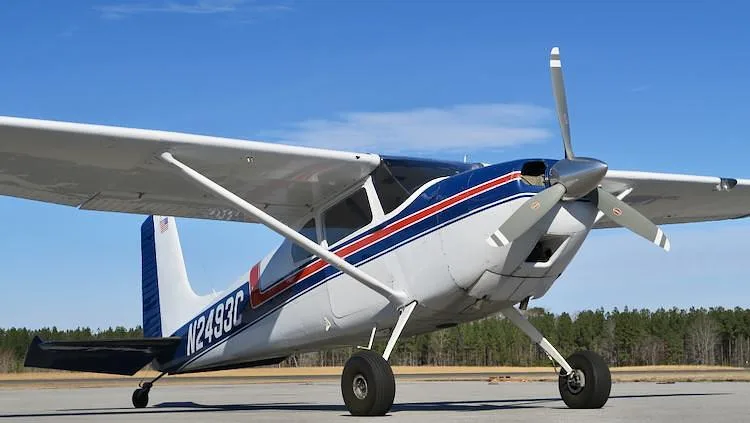
Free — save the 180 to your watchlist and track it in one place.
More CESSNA 180manuals & documents
See all 33 →- Instructions For Continued Airworthiness - Hartzell PropellerMaintenance Manual
- SEB-34-33-Stall-Warning-Horn-180-185-188.pdfParts Catalog
- AD 2020-21-22 - McFarlane AviationAirworthiness Directives
- Airworthiness Directive Schedule - Cessna 180 Series - CAAAirworthiness Directives
- Type Acceptance Report TAR 99/11 — Cessna 180 SeriesOther Documents
- Vizion Install Appendix E C180, C182-C182D, C185Wiring Diagram
- V-Speeds ReferenceOther Documents
- Over-wing Fuel Tank Vent Systems (Including Early Cessna 180 ...Service Bulletins
- CESSNA, 180, 182, Skylane, 185, Skywagon, Exhaust System.Systems Description
- ALERT SERVICE BULLETIN - Hartzell PropellerService Bulletins
- AD/CESSNA 180/89 - Crew Seat Back Cylinder Lock ModificationService Bulletins
- Airworthiness Directive - AD/CESSNA 180/90 - Fuel Line ChafingSupplemental Type Certificate
If you fly the CESSNA 180, you may also be researching these.


In this document
Introduction and Description
The AFWM Wing Strut Utility Mount is designed to attach to the wing struts of Cessna models 172, 180, 182, and 206. It can support a payload of up to 50 lbs with a frontal area of 1.0 ft². The mount can be installed on both the upper and lower sections of the left-hand wing strut and only on the upper section of the right-hand wing strut.
Installation Instructions
Installation requires locating an area on the wing strut approximately 12-18 inches from the ends of the fairing. The area must be cleaned, and rubber shims used for a proper fit. The mount is attached using AN hex bolts and should be torqued to specified values. After installation, weight and balance calculations must be updated.
Weight and Balance Information
The document provides specific weight and balance tables for each model (172, 180, 182, 206) detailing the weight of the mount and maximum payload. For example, the mount itself weighs 2.5 lbs, and the maximum payload is 50 lbs.
Removal Instructions
To remove the AFWM, the installed payload must first be removed, followed by the disassembly of the mount using the specified fasteners. The weight and balance must be updated after removal.
Safety Notes
If additional power is required for camera/sensor installations beyond the OEM auxiliary power outlet, additional certifications may be necessary. Proper weight and balance calculations are critical after installation.
Safety notes
- Ensure no gaps exist between the mount and wing strut during installation.
- Calculate weight and balance after installation and before flight.
Full document text
AIRFILM CAMERA SYSTEMS INC PROPRIETARY RIGHTS ARE INCLUDED IN THE INFORMATION DISCLOSED HEREIN. NEITHER THESE DOCUMENTS NOR THE INFORMATION DISCLOSED HEREIN SHALL BE REPRODUCED, USED, OR DISCLOSED IN WHOLE OR IN PART WITHOUT THE WRITTEN PERMISSION OF AIRFILM CAMERA SYSTEMS INC. AIRFILM CAMERA SYSTEMS REPORT AFWM-1-006 INSTALLATION INSTRUCTIONS AFWM WING STRUT UTILITY MOUNT FOR CESSNA 172, 180, 182, AND 206 AIRCRAFT DATE ISSUED: 01/15/2019 Airfilm Camera Systems 6245 Aerodrome Way, Hangar No. 2 Georgetown, CA 95634 LOG OF REVISIONS REVISION DATE PAGES EFFECTED COMMENTS N/C 01/15/2019 ALL Original Issue A 06/18/2020 ALL Revised Description and Installation Instructions for correct mount installation locations Airfilm Camera Systems AFWM WING STRUT UTILITY MOUNT INSTALLATION INSTRUCTIONS AFWM-1-006 Rev. A 1 AIRFILM CAMERA SYSTEMS INC PROPRIETARY RIGHTS ARE INCLUDED IN THE INFORMATION DISCLOSED HEREIN. NEITHER THESE DOCUMENTS NOR THE INFORMATION DISCLOSED HEREIN SHALL BE REPRODUCED, USED, OR DISCLOSED IN WHOLE OR IN PART WITHOUT THE WRITTEN PERMISSION OF AIRFILM CAMERA SYSTEMS INC. 1.0 INTRODUCTION AND DESCRIPTION: Figure 1. View Showing the AFWM-1 Installation on a Cessna 182 The Airfilm Camera Systems Wing Strut Utility Mount (AFWM) fastens to the strut near the wing attach point of the Cessna (Textron Aviation Inc.) models 172, 180, 182, and 206 to provide a means for attaching an external payload of up to 50 lbs with a frontal area of 1.0 ft2. Typical payloads could include but are not limited to: cameras, sensors, speakers, and lights. The AFWM Wing Strut Utility Mount can be installed on the upper and lower sections of the left-hand wing strut, and be installed on the upper section only of the right-hand wing strut. The mount can be installed on both wing struts simultaneously, when installed in the approved locations. A miniature version of the AFWM wing mount (AFWM-172M, AFWM-180M, AFWM-182M, and AFWM-206M) fastens to the wing strut of Cessna Aircraft and provides a mean for attaching an external payload of up to 10 lbs and a frontal area of 0.5 ft2. The AFWM Mini Wing Strut Mount can be installed anywhere the larger AFWM Wing Strut Mount can be installed. The Mini Wing Strut Mount can be installed simultaneously on both wing struts or opposite of a AFWM Wing Strut Mount, when installed in the approved locations. The AFWM Wing Strut Mount and AFWM Mini Strut Mounts are fabricated from 6061-T6 aluminum and attach with a hinged connection to the aircraft wing strut with AN Hex Bolts, AN960 Washers and AN365 Locking Nuts. After installation, calculate weight and balance for Installed items and check for proper loading of aircraft. Antenna, lights, and additional installed equipment may need to be relocated to provide clearance for the camera mount system. Airfilm Camera Systems AFWM WING STRUT UTILITY MOUNT INSTALLATION INSTRUCTIONS AFWM-1-006 Rev. A 2 AIRFILM CAMERA SYSTEMS INC PROPRIETARY RIGHTS ARE INCLUDED IN THE INFORMATION DISCLOSED HEREIN. NEITHER THESE DOCUMENTS NOR THE INFORMATION DISCLOSED HEREIN SHALL BE REPRODUCED, USED, OR DISCLOSED IN WHOLE OR IN PART WITHOUT THE WRITTEN PERMISSION OF AIRFILM CAMERA SYSTEMS INC. Note - If camera / sensor installations require additional power or system requirements beyond the placarded OEM auxiliary power outlet, additional certification(s) may be required. 2.0 AFWM WING STRUT UTILITY MOUNT INSTALLATION NOTE: Installation of the AFWM Wing Strut Utility Mount is approved for the upper and lower portion of the left-hand wing strut along with the upper portion of the right-hand wing strut. The mount is not to be installed on the lower portion of the right-hand wing strut. 1. Locate area on the wing strut approximately 12-18 inches from the upper or lower end of the wing strut fairing for installation. Clean the area of installation on the wing strut with rubbing alcohol. The approved installation area is shown in the figure below. Figure 2. Installation Location of the AFWM Wing Mount on the Strut of the Cessna Aircraft 2. Using the supplied rubber shims from the rubber shim kit (AFWM-RBKIT-101, AFWM- RBKIT-102, AFWM-RBKIT-103), shim wing strut mount for best fit. Use the varying thicknesses of rubber supplied in the kit to obtain a proper fit on the wing strut. Dry fit the assembled wing strut mount to ensure mount cannot move when fastened together. Ensure no gaps exist between the mount, rubber shims, and wing strut. Airfilm Camera Systems AFWM WING STRUT UTILITY MOUNT INSTALLATION INSTRUCTIONS AFWM-1-006 Rev. A 3 AIRFILM CAMERA SYSTEMS INC PROPRIETARY RIGHTS ARE INCLUDED IN THE INFORMATION DISCLOSED HEREIN. NEITHER THESE DOCUMENTS NOR THE INFORMATION DISCLOSED HEREIN SHALL BE REPRODUCED, USED, OR DISCLOSED IN WHOLE OR IN PART WITHOUT THE WRITTEN PERMISSION OF AIRFILM CAMERA SYSTEMS INC. Figure 3. Installation of the AFWM-RBKIT Rubber Shim Kit onto the Wing Strut 3. If installing with the DT-1-1 Quick Release Dovetail, attach the upper portion of the DT-1-1 (P/N DT-1-11) to AFWM-XXX-001 (LH) or AFWM-XXX-002 (RH) Lower Clamp (where ‘XXX’ depicts applicable model number) with AN4-10A hex bolts, MS21043-4 locking nuts, and AN960-416L washers. Torque hardware to 50-70 in-lbs per FAA AC43.13-1A. Installation of the DT-1-1 can be completed with the wing mount completely assembled. Figure 4. Exploded view of DT-1-1 Installation onto the AFWM Lower Clamp 4. Open the upper and lower Wing Mount Clamps and fit the AFWM Wing Mount Assembly onto the pre-installed rubber shims. Insert and hand-tighten the 3 AN3-6A hex bolts, AN960- 10L washers, and AN365-1032A nuts at the clamping portion of the wing mount. Leave Hand Tight. Airfilm Camera Systems AFWM WING STRUT UTILITY MOUNT INSTALLATION INSTRUCTIONS AFWM-1-006 Rev. A 4 AIRFILM CAMERA SYSTEMS INC PROPRIETARY RIGHTS ARE INCLUDED IN THE INFORMATION DISCLOSED HEREIN. NEITHER THESE DOCUMENTS NOR THE INFORMATION DISCLOSED HEREIN SHALL BE REPRODUCED, USED, OR
Show full textShow less
DISCLOSED IN WHOLE OR IN PART WITHOUT THE WRITTEN PERMISSION OF AIRFILM CAMERA SYSTEMS INC. Figure 5. Installation of the AFWM Wing Mount Assembly onto the Cessna Aircraft Wing Strut. 5. Ensure no interference is present between the wing strut, rubber shims, and the AFWM wing strut mount. Torque the AN3-10A clamping bolts to 20-25 in-lbs per FAA AC43.13-1B. After clamping bolts have been torqued to spec, torque the AN4 hinge bolt to 50-70 in-lbs at the forward portion of the wing mount. 6. Revise weight and balance per the following table: The following tables present the location of the weight/center of gravity of the mount and payload sensor/camera for adjustment of the aircraft weight and center of gravity with the mount installed. Table 1. AFWM-172 Cessna 172 Wing Mount Weight and Balance Information DESCRIPTION WEIGHT (lbs) STATION (in) MOUNT 2.5 25.0 Dovetail DT-1-1 (optional) 2.4 25.0 Spacer AFWM-SPCR-003 (optional) 0.5 25.0 PAYLOAD Use Actual Wt MAX 50 pounds. 25.0 Table 2. AFWM-180 Cessna 180 Wing Mount Weight and Balance Information DESCRIPTION WEIGHT (lbs) STATION (in) MOUNT 2.5 25.0 Dovetail DT-1-1 (optional) 2.4 25.0 Spacer AFWM-SPCR-003 (optional) 0.5 25.0 PAYLOAD Use Actual Wt MAX 50 pounds. 25.0 Table 3. AFWM-182 Cessna 182 Wing Mount Weight and Balance Information DESCRIPTION WEIGHT (lbs) STATION (in) MOUNT 2.5 25.0 Airfilm Camera Systems AFWM WING STRUT UTILITY MOUNT INSTALLATION INSTRUCTIONS AFWM-1-006 Rev. A 5 AIRFILM CAMERA SYSTEMS INC PROPRIETARY RIGHTS ARE INCLUDED IN THE INFORMATION DISCLOSED HEREIN. NEITHER THESE DOCUMENTS NOR THE INFORMATION DISCLOSED HEREIN SHALL BE REPRODUCED, USED, OR DISCLOSED IN WHOLE OR IN PART WITHOUT THE WRITTEN PERMISSION OF AIRFILM CAMERA SYSTEMS INC. Dovetail DT-1-1 (optional) 2.4 25.0 Spacer AFWM-SPCR-003 (optional) 0.5 25.0 PAYLOAD Use Actual Wt MAX 50 pounds. 25.0 Table 4. AFWM-206 Cessna 206 Wing Mount Weight and Balance Information DESCRIPTION WEIGHT (lbs) STATION (in) MOUNT 2.5 26.0 Dovetail DT-1-1 (optional) 2.4 26.0 Spacer AFWM-SPCR-003 (optional) 0.5 26.0 PAYLOAD Use Actual Wt MAX 50 pounds. 26.0 7. Make appropriate logbook entry for installation. 8. Return to service. NOTES: a) The payload package for the installation is limited to a maximum allowable frontal area of 1.0 ft² and a Maximum weight of 50 lbs at any mounting location. b) When Airfilm Payload Disconnect Devices (DT-1-1) are installed, the payload can be removed and installed by crew. Payload can be direct mounted to the AFWM Wing Strut Mount using approved hardware. c) If camera/sensor installations require additional power or system requirements beyond the placarded OEM auxiliary power outlet, additional certification(s) may be required. AFWM-172, AFWM-180, AFWM-182, and AFWM-206 Wing Strut Mount Removal Instructions: 1. Remove any installed payload from the Wing Strut Utility Mount. 2. Remove the fasteners (3X AN3-6A Bolts) from the clamping aft facing end of the Wing Strut Mount. Loosen the forward hinge bolt and allow the mount to rotate open and be removed from the Cessna Wing Strut. 3. Remove the rubber shim material from the Cessna Wing Strut Mount. 4. Update the aircraft weight and balance. 3.0 AFWM MINI WING STRUT UTILITY MOUNT INSTALLATION NOTE: Installation of the AFWM Mini Wing Strut Utility Mount is approved for the upper and lower portion of the left-hand wing strut along with the upper portion of the right-hand wing strut. The mount is not to be installed on the lower portion of the right-hand wing strut. 1. Locate area on the wing strut approximately 12-18 inches from the upper or lower end of the wing strut fairing for installation. Clean the area of installation on the wing strut with rubbing alcohol. The approved installation area is shown in the figure below. Airfilm Camera Systems AFWM WING STRUT UTILITY MOUNT INSTALLATION INSTRUCTIONS AFWM-1-006 Rev. A 6 AIRFILM CAMERA SYSTEMS INC PROPRIETARY RIGHTS ARE INCLUDED IN THE INFORMATION DISCLOSED HEREIN. NEITHER THESE DOCUMENTS NOR THE INFORMATION DISCLOSED HEREIN SHALL BE REPRODUCED, USED, OR DISCLOSED IN WHOLE OR IN PART WITHOUT THE WRITTEN PERMISSION OF AIRFILM CAMERA SYSTEMS INC. Figure 6. Installation Location of the AFWM Mini Wing Strut Mount on the Strut of the Cessna Aircraft 2. Using the supplied rubber shims from the rubber shim kit (AFWM-RBKIT-107, AFWM- RBKIT-108, AFWM-RBKIT-109), shim wing strut mount for best fit. Use the varying thicknesses of rubber supplied in the kit to obtain a proper fit on the wing strut. Dry fit the assembled wing strut mount to ensure mount cannot move when fastened together. Ensure no gaps exist between the mount, rubber shims, and wing strut. Figure 7. Installation of the AFWM-RBKIT Rubber Shim Kit onto the Wing Strut 3. Fit the AFWM Mini Wing Strut Mount onto the aircraft strut where the rubber shims are installed. Insert and hand-tighten the 4X AN3-6A hex bolts, 8X AN960-10L washers, and 4X AN365-1032A nuts at the forward and aft clamping portions of the wing mount. Leave Hand Tight. Airfilm Camera Systems AFWM WING STRUT UTILITY MOUNT INSTALLATION INSTRUCTIONS AFWM-1-006 Rev. A 7 AIRFILM CAMERA SYSTEMS INC PROPRIETARY RIGHTS ARE INCLUDED IN THE INFORMATION DISCLOSED HEREIN. NEITHER THESE DOCUMENTS NOR THE INFORMATION DISCLOSED HEREIN SHALL BE REPRODUCED, USED, OR DISCLOSED IN WHOLE OR IN PART WITHOUT THE WRITTEN PERMISSION OF AIRFILM CAMERA SYSTEMS INC. Figure 8. Installation of the AFWM Mini Wing Strut Mount onto the Cessna Wing Strut Figure 9. AFWM Mini Wing Strut Mount installed onto the Cessna Wing Strut 4. Ensure no interference is present between the wing strut, rubber shims, and the AFWM Mini Wing Strut Mount. Torque the AN3-6A clamping bolts to 20-25 in-lbs per FAA AC43.13-1B. Ensure the four clamping bolts are torqued evenly to ensure even clamping pressure on the Cessna Wing Strut. 5. Revise weight and balance per the following table: The following tables present the location of the weight/center of gravity of the mount and payload sensor/camera for adjustment of the aircraft weight and center of gravity with the mount installed. Airfilm Camera Systems AFWM WING STRUT UTILITY MOUNT INSTALLATION INSTRUCTIONS AFWM-1-006 Rev. A 8 AIRFILM CAMERA SYSTEMS INC PROPRIETARY RIGHTS ARE INCLUDED IN THE INFORMATION DISCLOSED HEREIN. NEITHER THESE DOCUMENTS NOR THE INFORMATION DISCLOSED HEREIN SHALL BE REPRODUCED, USED, OR DISCLOSED IN WHOLE OR IN PART WITHOUT THE WRITTEN PERMISSION OF AIRFILM CAMERA SYSTEMS INC. Table 5. AFWM-172M Cessna 172 Mini Wing Mount Weight and Balance Information DESCRIPTION WEIGHT (lbs) STATION (in) MOUNT 1.5 25.0 PAYLOAD Use Actual Wt MAX 10 pounds. 25.0 Table 6. AFWM-180M Cessna 180 Mini Wing Mount Weight and Balance Information DESCRIPTION WEIGHT (lbs) STATION (in) MOUNT 1.5 25.0 PAYLOAD Use Actual Wt MAX 10 pounds. 25.0 Table 7. AFWM-182M Cessna 182 Mini Wing Mount Weight and Balance Information DESCRIPTION WEIGHT (lbs) STATION (in) MOUNT 1.5 25.0 PAYLOAD Use Actual Wt MAX 10 pounds. 25.0 Table 8. AFWM-206M Cessna 206 Mini Wing Mount Weight and Balance Information DESCRIPTION WEIGHT (lbs) STATION (in) MOUNT 1.5 26.0 PAYLOAD Use Actual Wt MAX 10 pounds. 26.0 6. Make appropriate logbook entry for installation. 7. Return to service. NOTES: a) The payload package for the installation is limited to a maximum allowable frontal area of 0.5 ft² and a weight of 10 lbs at any mounting location. b) If camera/sensor installations require additional power or system requirements beyond the placarded OEM auxiliary power outlet, additional certification(s) may be required. AFWM-172M, AFWM-180M, AFWM-182M, and AFWM-206M Mini Wing Strut Mount Removal Instructions: 1. Remove any installed payload from the Mini Wing Strut Utility Mount. 2. Remove the fasteners (4X AN3-6A Bolts) from the forward and aft clamping portions the Mini Wing Strut Mount. Support the two halves of the Wing Strut Clamp and allow the mount to be removed from the Cessna Wing Strut. Airfilm Camera Systems AFWM WING STRUT UTILITY MOUNT INSTALLATION INSTRUCTIONS AFWM-1-006 Rev. A 9 AIRFILM CAMERA SYSTEMS INC PROPRIETARY RIGHTS ARE INCLUDED IN THE INFORMATION DISCLOSED HEREIN. NEITHER THESE DOCUMENTS NOR THE INFORMATION DISCLOSED HEREIN SHALL BE REPRODUCED, USED, OR DISCLOSED IN WHOLE OR IN PART WITHOUT THE WRITTEN PERMISSION OF AIRFILM CAMERA SYSTEMS INC. 3. Remove the rubber shim material from the Cessna Wing Strut Mount. 4. Update the aircraft weight and balance. Airfilm Camera Systems AFWM WING STRUT UTILITY MOUNT INSTALLATION INSTRUCTIONS AFWM-1-006 Rev. A 10 AIRFILM CAMERA SYSTEMS INC PROPRIETARY RIGHTS ARE INCLUDED IN THE INFORMATION DISCLOSED HEREIN. NEITHER THESE DOCUMENTS NOR THE INFORMATION DISCLOSED HEREIN SHALL BE REPRODUCED, USED, OR DISCLOSED IN WHOLE OR IN PART WITHOUT THE WRITTEN PERMISSION OF AIRFILM CAMERA SYSTEMS INC. 4.0 AFWM-SPCR Payload Spacer Installation Instructions (Optional) Spacer blocks can be added between the base of the mount and the payload to provide additional clearance from the strut. Refer to the following instructions for installation of the optional spacer configurations. AFWM-SPCR-001 0.5 Inch Spacer Installation Instructions: Figure 10. Exploded view of AFWM-SPCR-1 Assembly with Reference DT-1-1 Quick Disconnect 1. With the AFWM Wing Strut Mount Removed from the aircraft, install the AFWM-SPCR- 003 0.5 inch spacer onto the bottom face of the AFWM Wing Strut Mount Lower Clamp using 5X AN4 hex bolts, 10X AN960-416 Washers, and 5X MS21043 Locking Nuts. The grip length of the AN4 bolts are to be determined on installation of the spacer and payload depending on the payload configuration used. 2. Ensure proper thread engagement is present between the nut and bolt. Refer to document AC43.13-1B for standard practices when determining fastener length. Torque fasteners to 50- 70 in-lbs on the nut side of the fastener connection per AC43.13-1B. 3. Refer to Figure 10 for spacer and fastener stack-up. DT-1-1 quick disconnect device shown for reference. Airfilm Camera Systems AFWM WING STRUT UTILITY MOUNT INSTALLATION INSTRUCTIONS AFWM-1-006 Rev. A 11 AIRFILM CAMERA SYSTEMS INC PROPRIETARY RIGHTS ARE INCLUDED IN THE INFORMATION DISCLOSED HEREIN. NEITHER THESE DOCUMENTS NOR THE INFORMATION DISCLOSED HEREIN SHALL BE REPRODUCED, USED, OR DISCLOSED IN WHOLE OR IN PART WITHOUT THE WRITTEN PERMISSION OF AIRFILM CAMERA SYSTEMS INC. AFWM-SPCR-003 1.5 Inch Spacer Installation Instructions: Figure 11. Exploded view of AFWM-SPCR-3 Assembly with Reference Payload Location 1. With the AFWM Wing Strut Mount Removed from the aircraft, install three (3X) AFWM- SPCR-003 0.5 inch spacers onto the bottom face of the AFWM Wing Strut Mount Lower Clamp using 5X AN4 hex bolts, 10X AN960-416 Washers, and 5X MS21043 Locking Nuts. The grip length of the AN4 bolts are to be determined on installation of the spacer and payload depending on the payload configuration used. 2. Ensure proper thread engagement is present between the nut and bolt. Refer to document AC43.13-1B for standard practices when determining fastener length. Torque fasteners to 50- 70 in-lbs on the nut side of the fastener connection per AC43.13-1B. 3. Refer to Figure 11 for spacer and fastener stack-up. The location of the payload is shown for reference and is to be installed under the AFWM-SPCR-3 Spacers. Airfilm Camera Systems AFWM WING STRUT UTILITY MOUNT INSTALLATION INSTRUCTIONS AFWM-1-006 Rev. A 12 AIRFILM CAMERA SYSTEMS INC PROPRIETARY RIGHTS ARE INCLUDED IN THE INFORMATION DISCLOSED HEREIN. NEITHER THESE DOCUMENTS NOR THE INFORMATION DISCLOSED HEREIN SHALL BE REPRODUCED, USED, OR DISCLOSED IN WHOLE OR IN PART WITHOUT THE WRITTEN PERMISSION OF AIRFILM CAMERA SYSTEMS INC. AFWM-SPCR-005 Lower Dovetail Installation Instructions: Figure 12. Exploded view of AFWM-SPCR-3 Assembly with Reference Payload Location 1. With the DT-1-1 Lower Dovetail removed from the AFWM Wing Strut Mount, install the AFWM-SPCR-001 0.5 inch spacer onto the bottom face of the DT-1-1 Lower Dovetail using 4X AN4 hex bolts, 8X AN960-416 Washers, and 4X MS21043 Locking Nuts. The grip length of the AN4 bolts are to be determined on installation of the spacer and payload depending on the payload configuration used. 2. Ensure proper thread engagement is present between the nut and bolt. Refer to document AC43.13-1B for standard practices when determining fastener length. Torque fasteners to 50- 70 in-lbs on the nut side of the fastener connection per AC43.13-1B. 3. Refer to Figure 11 for spacer and fastener stack-up. The location of the payload is assumed to be placed underneath the AFWM-SPCR-5 Lower Dovetail Spacer. Airfilm Camera Systems AFWM WING STRUT UTILITY MOUNT INSTALLATION INSTRUCTIONS AFWM-1-006 Rev. A 13 AIRFILM CAMERA SYSTEMS INC PROPRIETARY RIGHTS ARE INCLUDED IN THE INFORMATION DISCLOSED HEREIN. NEITHER THESE DOCUMENTS NOR THE INFORMATION DISCLOSED HEREIN SHALL BE REPRODUCED, USED, OR DISCLOSED IN WHOLE OR IN PART WITHOUT THE WRITTEN PERMISSION OF AIRFILM CAMERA SYSTEMS INC. APPENDIX A – METHOD OF ADDING ADDITIONAL SENSOR /CAMERA / PAYLOADS Overview This Appendix provides the requirements necessary to qualify sensor / camera / light payloads – IF NEEDED. It may also be used as a check list for previously approved sensor /cameras / light payloads if desired. The STC flight testing was conducted and the STC approved with the largest and heaviest payload expected for use with this mount. The specific sensor/cameras/light not listed in the installation manual of equal or lesser than the limit case are accepted with this follow-on test plan. Sensor/ Camera/ payload Make & Model ________________________________ Test Team Pilot(s) _________________________________ ________________________________ Print Name Mechanic and/or Engineer and/or Camera Operator _______________________________ _____________________________ Print Name Airfilm Camera Systems AFWM WING STRUT UTILITY MOUNT INSTALLATION INSTRUCTIONS AFWM-1-006 Rev. A 14 AIRFILM CAMERA SYSTEMS INC PROPRIETARY RIGHTS ARE INCLUDED IN THE INFORMATION DISCLOSED HEREIN. NEITHER THESE DOCUMENTS NOR THE INFORMATION DISCLOSED HEREIN SHALL BE REPRODUCED, USED, OR DISCLOSED IN WHOLE OR IN PART WITHOUT THE WRITTEN PERMISSION OF AIRFILM CAMERA SYSTEMS INC. 1. Test Aircraft Configuration and Location Aircraft Model, Registration & Serial Number ________________ _______________________ _______________________ Model Registration Number Serial Number Test Configurations Empty weight with appropriate fuel and camera system installed Takeoff Gross weight with crew Configuration Gross Weight Longitudinal CG Lateral CG Empty Wt Takeoff Wt 1.1. Test Location _________________________________ Airport or Test Site 2. Test Conditions Date: ___________________ Weather: Ceiling ______________ Visibility ______________ Winds ________________ Altimeter ___________ Field Elevation _____________ Flight Time: Engine Start _____________ Shut Down _____________ Flt Time ______ 3. Flight Test 3.1. Overview The testing required for the compliance findings of this installation will be made by as a subject/qualitative evaluation. Although the most critical CG is at the aft limit for most tests this configuration is mounted forward of the mast should not approach the aft limits. This also depends on crew loading. The test team conducts the following tests and evaluations and mark initial the box at the end of each section if the configuration successfully passes the requirements. Airfilm Camera Systems AFWM WING STRUT UTILITY MOUNT INSTALLATION INSTRUCTIONS AFWM-1-006 Rev. A 15 AIRFILM CAMERA SYSTEMS INC PROPRIETARY RIGHTS ARE INCLUDED IN THE INFORMATION DISCLOSED HEREIN. NEITHER THESE DOCUMENTS NOR THE INFORMATION DISCLOSED HEREIN SHALL BE REPRODUCED, USED, OR DISCLOSED IN WHOLE OR IN PART WITHOUT THE WRITTEN PERMISSION OF AIRFILM CAMERA SYSTEMS INC. 3.2. FAR § 27.51 Takeoff The weight at which the takeoff roll of the modified aircraft, in the highest drag configuration, is equal to or less than that of the unmodified airplane will be determined using the Segment Technique per AC 23-8C, Section 2 para 4.b.(2). Tests will be conducted on the unmodified and modified aircraft. The takeoff run to rotation at a speed of VX plus 4 knots will be marked by ground observers. 3.2.1. Test Procedure: Hold brakes. Run up engine to takeoff power. Release brakes. Accelerate to VX plus 4 knots and rotate. Record: 1) pressure altitude; 2) takeoff weight; 3) runway slope. 4) headwind; 6) outside air temperature; 7) distance from brake release to rotation. Data Reduction: The test results of the unmodified aircraft will be corrected for weight but will be considered acceptable without correction for weight if a ±0.5 percent weight tolerance is observed. The test results will be corrected if the atmospheric conditions during the unmodified and modified tests present a difference in density altitude greater than 500 feet. The tests will be conducted on the same runway, eliminating the effect of runway gradient. The effect of headwind will be corrected per AC 23-8C Section 2 para 4.b.(5) should the headwind during unmodified and modified tests differ by more than 3 knots. A qualitative evaluation of the ability to safely land at any point along the flight path will be made using judgment and experience with the basic aircraft. No engine failure testing at low altitude will be conducted. The normal takeoff procedures will be used for the sensor/camera/light payload and mount installation. 3.2.2. Findings Satisfactory _________ 3.3. FAR § 23.143 Controllability and Maneuverability The airplane will be safely controllable and maneuverable during all flight phases including takeoff, climb, level flight, descent, go-around, and landing. It will be possible to make a smooth transition from one flight condition to another without danger of exceeding the limit load factor, under any probable operating condition. If marginal conditions exist with regard to required pilot strength, the appropriate control forces will be determined by quantitative tests. In no case will the control forces exceed the following: Airfilm Camera Systems AFWM WING STRUT UTILITY MOUNT INSTALLATION INSTRUCTIONS AFWM-1-006 Rev. A 16 AIRFILM CAMERA SYSTEMS INC PROPRIETARY RIGHTS ARE INCLUDED IN THE INFORMATION DISCLOSED HEREIN. NEITHER THESE DOCUMENTS NOR THE INFORMATION DISCLOSED HEREIN SHALL BE REPRODUCED, USED, OR DISCLOSED IN WHOLE OR IN PART WITHOUT THE WRITTEN PERMISSION OF AIRFILM CAMERA SYSTEMS INC. Temporary (two hands on the yoke) Pitch 75 lbs Roll 50 lbs Yaw 150 lbs Temporary (one hand on the yoke) Pitch 50 lbs Roll 25 lbs Yaw 150 lbs Prolonged Pitch 10 lbs Roll 5 lbs Yaw 20 lbs “Temporary” will be defined as the period of time necessary to trim the airplane and change the airspeed and configuration as necessary to relieve the control forces “Prolonged” will be defined as those control forces that cannot be relieve by changing trim, airspeed or configuration. Controllability will be deemed "satisfactory" or "unsatisfactory." Unsatisfactory controllability will exist if the test pilot finds it so inadequate that a dangerous condition might easily occur and is unacceptable as a showing of compliance with the regulations. Maneuverability will be a qualitative judgement and treated in the same manner as controllability. Tests will be conducted with a test shape mounted on both sides, and also a single test shape mounted outboard on the critical side. The critical side will be determined by the stall characteristics of the unmodified aircraft. 3.3.1. Test Procedure: In the noted phase of flight and configuration, record: 1) ability to safely control and maneuver airplane. Use the AFM recommended procedures for takeoff, approach and landing. The aircraft should be easily controllable and adequate control margins should exist throughout the flight test points. The difference between the mount and sensor / camera / light payload and the clean configuration is the evaluation point. 3.3.2. Findings Satisfactory _________ Cruise Altitude HP ________ Fuel Gage Reading _______ Airfilm Camera Systems AFWM WING STRUT UTILITY MOUNT INSTALLATION INSTRUCTIONS AFWM-1-006 Rev. A 17 AIRFILM CAMERA SYSTEMS INC PROPRIETARY RIGHTS ARE INCLUDED IN THE INFORMATION DISCLOSED HEREIN. NEITHER THESE DOCUMENTS NOR THE INFORMATION DISCLOSED HEREIN SHALL BE REPRODUCED, USED, OR DISCLOSED IN WHOLE OR IN PART WITHOUT THE WRITTEN PERMISSION OF AIRFILM CAMERA SYSTEMS INC. 3.4. FAR § 23.171 Stability: General The airplane will be longitudinally, directionally, and laterally stable under §§23.173 through 23.177. In addition, the airplane will show suitable stability and control “feel” (static stability) in any condition normally encountered in service if flight tests show it is necessary for safe operation. Test methods will entail qualitative determinations. The magnitude of the forces will increase with departure from the trim speed up to a speed limit or up to the 40-pound force limit specified in § 23.173. A pull force will be required to fly slower than trim and a push force required to fly faster than trim and the gradient will be clearly perceptible to the pilot. Compliance for this requirement will be evaluated throughout the test program. 3.4.1. Findings Satisfactory _________ 3.5. FAR § 23.251 Vibration 3.5.1. Applicable Regulation Each part of the aircraft must be free from excessive vibration under each appropriate speed and power condition. 3.5.2. Method of Compliance This flight requirement may be both a qualitative and quantitative flight evaluation. The airspeed should be evaluated at 20 kt increments out to the AFM VNE speed. Changes in vibration are best sensed in stick and pedal controls. The stability of the camera/sensor image will be a good indicator. The pilot will make a subjective evaluation of the difference between the mount and sensor / camera/ light payload and the clean configuration is the evaluation point. Compliance with this requirement will be evaluated during testing of FAR §23.143 Controllability and Maneuverability. 3.5.3. Findings Satisfactory _________ Airfilm Camera Systems AFWM WING STRUT UTILITY MOUNT INSTALLATION INSTRUCTIONS AFWM-1-006 Rev. A 18 AIRFILM CAMERA SYSTEMS INC PROPRIETARY RIGHTS ARE INCLUDED IN THE INFORMATION DISCLOSED HEREIN. NEITHER THESE DOCUMENTS NOR THE INFORMATION DISCLOSED HEREIN SHALL BE REPRODUCED, USED, OR DISCLOSED IN WHOLE OR IN PART WITHOUT THE WRITTEN PERMISSION OF AIRFILM CAMERA SYSTEMS INC. 3.6. FAR § 23.1301 Function and Installation. 3.6.1. Applicable Regulation Each item of installed equipment must-- (a) Be of a kind and design appropriate to its intended function (b) Be labeled as to its identification, function, or operating limitations, or any applicable combination of these factors; (c) Be installed according to limitations specified for that equipment; and (d) Function properly when installed. 3.6.2. Method of Compliance For optional equipment, the emphasis on functioning is rather limited compared to that for required equipment. The conditions under which the optional equipment is evaluated should be recorded in the report. The major emphasis for this type of equipment should be to ensure it does not interfere with the operation of systems that are required for safe operation of the aircraft, and that the failure modes are acceptable and do not create any hazards. During flight operations, operate all avionics and electrical systems. Complete the matrix below. The matrix is laid out with the newly installed equipment listed at the top of the page and all aircraft systems listed down the left side of the page. Note any EMI or RFI either TO or FROM the installed equipment. Note any anomalies or EMI/RFI interference to other instruments or indications during all testing phases of flight. Each item must be checked. Check off each block if no interference is noted. If interference is present during the test, DO NOT CHECK THE BOX and explain in Comments section at end of section. If applicable, note relevant conditions (i.e. frequencies, OBI selection, function modes) under which the interference occurred. Airfilm Camera Systems AFWM WING STRUT UTILITY MOUNT INSTALLATION INSTRUCTIONS AFWM-1-006 Rev. A 19 AIRFILM CAMERA SYSTEMS INC PROPRIETARY RIGHTS ARE INCLUDED IN THE INFORMATION DISCLOSED HEREIN. NEITHER THESE DOCUMENTS NOR THE INFORMATION DISCLOSED HEREIN SHALL BE REPRODUCED, USED, OR DISCLOSED IN WHOLE OR IN PART WITHOUT THE WRITTEN PERMISSION OF AIRFILM CAMERA SYSTEMS INC. 3.6.3. Findings Interference? Camera/Sensor/Light Position Controller Camera/Sensor/Light Position Controller VHF Comm 1 VHF Comm 2 VHF Comm 3 VHF NAV 1 VHF NAV 2 ADF 1 XPONDER 1 Other Radios Audio 1 Audio 2 Standby Compass Engine Inst Fuel Gage Clock Voltmeter Ammeter Other EMI / RFI Comments: Satisfactory _________ Airfilm Camera Systems AFWM WING STRUT UTILITY MOUNT INSTALLATION INSTRUCTIONS AFWM-1-006 Rev. A 20 AIRFILM CAMERA SYSTEMS INC PROPRIETARY RIGHTS ARE INCLUDED IN THE INFORMATION DISCLOSED HEREIN. NEITHER THESE DOCUMENTS NOR THE INFORMATION DISCLOSED HEREIN SHALL BE REPRODUCED, USED, OR DISCLOSED IN WHOLE OR IN PART WITHOUT THE WRITTEN PERMISSION OF AIRFILM CAMERA SYSTEMS INC. Signatures General test findings ________________________________ Pilot Signature ____________________________ Mechanic/ Engineer ____________________________ Other Flt Personnel Signature & Function ______________________________________
What's in the CESSNA 180 TCDS
A Type Certificate Data Sheet (TCDS) is the FAA's record of what an aircraft type was approved as. It is the source of truth for weights, seating, fuel and the rules the design was certified against. Expand any line to see what it means.
740 CESSNA 180 parts for sale
See all →


Parts listed for sale by vetted eBay sellers — confirmed on eBay at checkout.