GENERAL AVIATION INSPECTION AIDS
CESSNA 310L · Other Documents
Overview
The document titled 'General Aviation Inspection Aids' serves as a comprehensive resource for the aviation community, focusing on the inspection, maintenance, and operation of various aircraft, including the Cessna 310L. It aims to improve the safety and durability of aeronautical products by sharing service experiences and recommendations. The publication is intended for mechanics, aircraft operators, and pilots, providing insights into common issues, maintenance practices, and safety measures. It emphasizes the importance of reporting malfunctions and defects to enhance collective knowledge and safety in aviation operations.
- Regular inspections are crucial for maintaining aircraft safety and reliability.
- Operators should report any malfunctions or defects to the FAA using the appropriate forms.
- Corrosion and structural integrity should be prioritized during inspections.
- Adherence to manufacturer maintenance guidelines is essential for aircraft longevity.
- Safety practices should be integrated into daily operations to mitigate risks.
Document
Source
Originally published by rosap.ntl.bts.gov. Sprinkle hosts a reference copy with an added summary, specifications and searchable full text.
Document details
- Type
- Other Documents
- Year
- 1977
- Pages
- 296
- File size
- 16 MB
- Publisher
- rosap.ntl.bts.gov
Common. Rarer than 2% of the aircraft models we track.
Most owners only have the POH. Here's the essential set for the CESSNA 310L.
- Pilot's Operating Handbook / AFM
- Checklist
- Maintenance Manual
- Parts Catalog (IPC)
- Systems & Wiring
- Service Bulletins
- Type Certificate (TCDS)
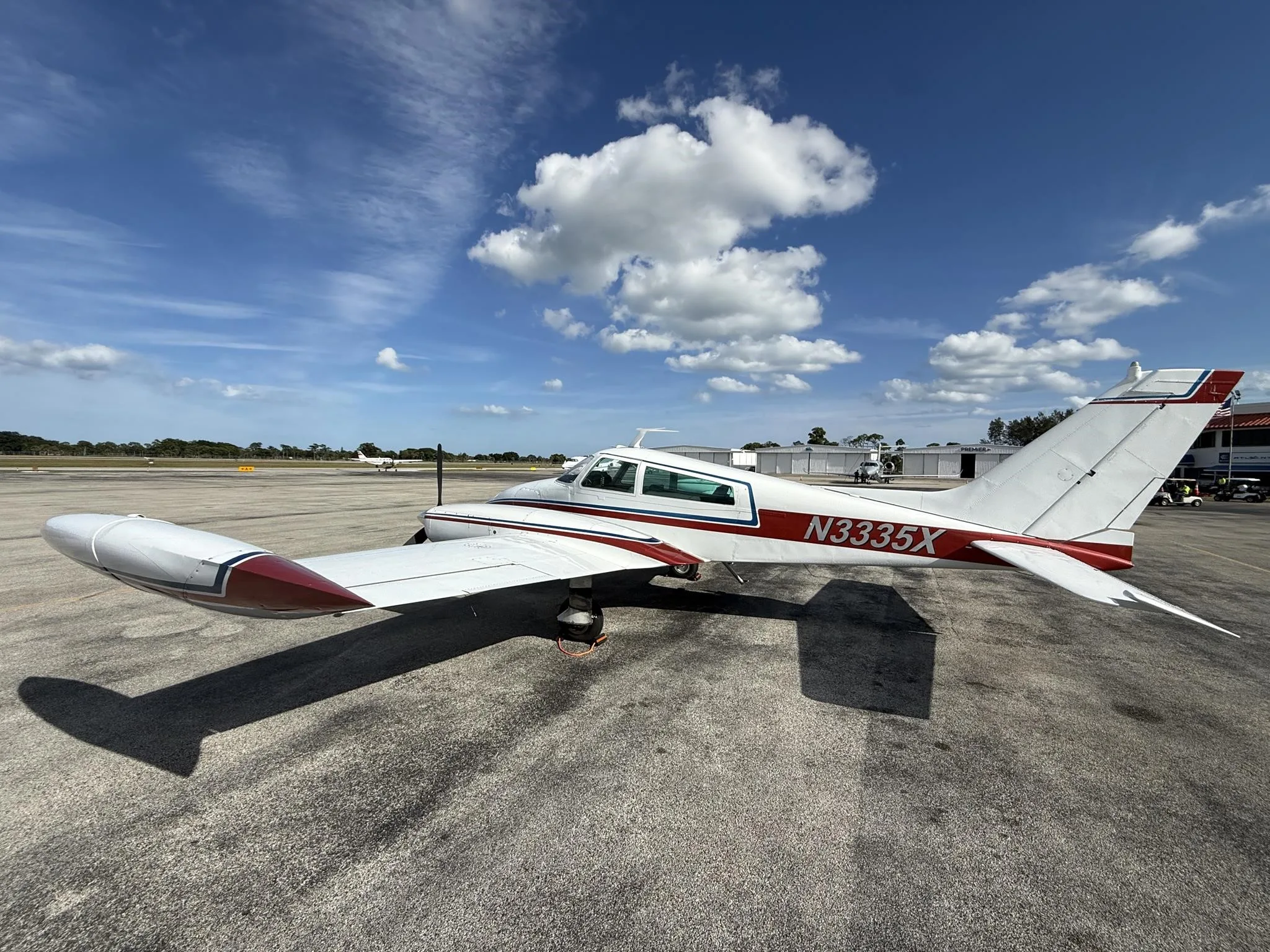
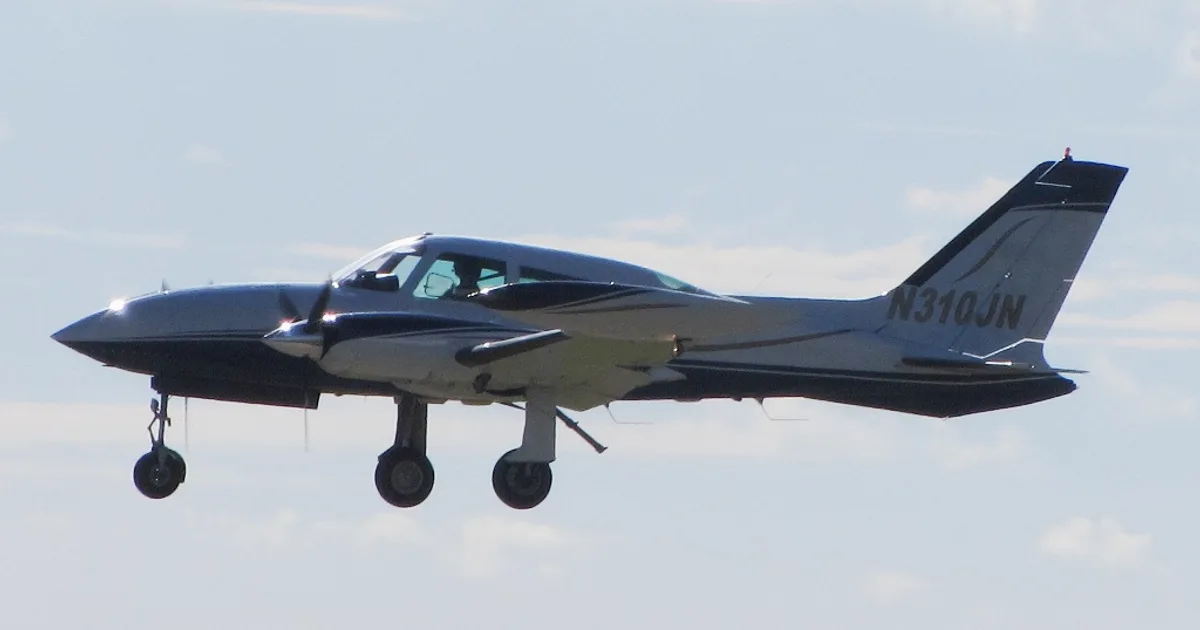
CESSNA 310L for sale now

Free — save the 310L to your watchlist and track it in one place.
More CESSNA 310Lmanuals & documents
See all 19 →- PILOT SUPPLIES - Wing Aero ProductsTraining Manual
- Airworthiness Directive Schedule Amendment Nr 24-07 - CAAOther Documents
- Weight & Balance Guide - ForeFlightWeight And Balance
- PMA Application and Pump Cross Reference - Aircraft SpruceService Bulletins
- EASA - J.P. InstrumentsSupplemental Type Certificate
- 28V Alternator Controller Units (ACU) Cross ReferenceWiring Diagram
- AAIB Bulletin No: 2/2004Service Bulletins
- Airworthiness Directives; McCauley Accessory Division, The Cessna Aircraft Company, Model C35, C72, C74, C75, C80, C86, C87, C92, and C93 Series PropellersService Bulletins
- SCHEDULE OF AIRWORTHINESS DIRECTIVESAirworthiness Directives
- Aviation Safety Digest 117Other Documents
- PILOT'S OPERATING HANDBOOK - flight examinersPilot's Operating Handbook
- Cessna 310L, G-AZUYOther Documents
If you fly the CESSNA 310L, you may also be researching these.



In this document
Introduction
The introduction outlines the purpose of the General Aviation Inspection Aids, which is to provide updated information on aircraft maintenance and safety based on service experiences. It encourages the aviation community to report any malfunctions or defects to improve overall safety.
Aircraft Inspection
This section discusses the importance of regular inspections for various aircraft components, including the Cessna 310L. It highlights specific areas to focus on during inspections, such as corrosion, structural integrity, and compliance with manufacturer guidelines.
Maintenance Recommendations
The document provides maintenance recommendations for aircraft operators, including the Cessna 310L. It emphasizes the need for routine checks and adherence to service bulletins to ensure aircraft reliability and safety.
Reporting Malfunctions
This section stresses the importance of reporting any malfunctions or defects encountered during aircraft operation. It provides guidance on how to submit reports to the FAA, which helps in gathering data for improving aircraft safety.
Safety Practices
The safety practices section outlines best practices for aircraft operation and maintenance, including pre-flight checks and emergency procedures. It aims to enhance pilot awareness and preparedness for various flight scenarios.
Safety notes
- Always report malfunctions or defects to the FAA to contribute to aviation safety.
- Inspect for corrosion and structural issues regularly to prevent in-flight failures.
- Follow manufacturer guidelines for maintenance to ensure compliance and safety.
Full document text
AC NO. 20-7P GENERAL AVIATION i n s p e c t i o n SUMMARY AUGUST 1 9 7 7 U . S . D E P A R T M E N T O F T R A N S P O R T A T I O N F E D E R A L A V I A T I O N A D M I N I S T R A T I O N Flight Standards Service PREFACE The General Aviation Inspection Aids publication provides the aviation community with a uniform means for interchanging service experience which is intended to improve the durability and safety of aeronautical products. It is hoped that this exchange of brief, advisory data wiU be of value to mechanics, operators of repair stations, and others en gaged in the inspection, maintenance, and operation of aircraft in general. The information contained in the Aids publication is in no way intended to be critical of any manufacturer or his product. Rather, it is expected to alert the aviation community to maintainability data gained through service experience. When possible, manufacturers' suggestions for improvements to their products have been included. The recommenda tions which are contained in the Aids, however, are not mandatory. When the information is made available, this publication includes data on the service experience of V. S. manufactured aircraft that have been exported and are operating in foreign countries. In addition, information is also provided on those aircraft of foreign manufacture that have been issued an FAA Certificate of Airworthiness. To advance the exchange of in-service information such as that available in this publi cation, the FAA encourages all persons in the aviation community (including aircraft owners, mechanics, pilots, and manufacturers) to promptly report their experiences by submitting a Malfunction or Defect Report (FAA Form 8330-2), Copies of this form, commonly referred to as an M i? D Report, may be obtained, free of charge, from most airport managers or at any FAA District Office. This form requires no postage and is preaddressed to receive prompt handling. For the purpose of accurately determining the scope, complexity, and growth of con ditions encountered in service, it is essential that all experiences be reported as they occur, even though such information may have already appeared in the General Avia tion Inspection Aids. The results of such cooperative action, on the part of everyone concerned, will provide the means for measuring the validity and effectiveness of cor rective actions taken by manufacturers and the Federal Aviation Administration's Flight Standards Service. F o r sale by the Superintendent of D o c u m e n t s , U . S . G o v e r n m e n t Printing Office Washington, D . C . 20402 U.S. DEPARTMENT OF TRANSPORTATION FEDERAL AVIATION ADMINISTRATION WASHINGTON, D.C. 20590 GENERAL AVIATION INSPECTION AIDS Table of Contents A I R C R A F T AVIONS MARCEL DASSAULT 3 BALLOON WORKS 3 BEAGLE AIRCRAFT LTD 4 BEECH . 4-10, 147 BELL 10-12, 147 BELLANCA 12-15 BOEING 15 BOLKOW , . . . . „ . 15 CESSNA 15-34, 147 CURTISS-WRIGHT 34 DeHAVILLAND 34-36 ENSTROM 36-37 FAIRCHILD INDUSTRIES 37-40, 148 GENERAL DYNAMICS 41 GRUMMAN 41 GRUMMAN-AMERICAN 41-45, 148-149 HELIO . 45 HILLER 45-46 INTERCEPTOR 46 ISRAEL AIRCRAFT 46 LAKE 47 LEAR 47 LET 149 MARTIN 48 MAULE 48 MCDONNELL DOUGLAS 49 MITSUBISHI 50 MOONEY 50-53, 14ft NAVION 53 NORTH AMERICAN 53 PIPER 53-85, 149-152 ROCKWELL INTERNATIONAL 85-88, 152 GENERAL AVIATION INSPECTION AIDS SUMMARY A I R F R A M E C O M P O N E N T S CLEVELAND 92 GOODYEAR 92 PEE-KAY. 93 A P P L I A N C E S ACCESSORIES AIRESEARCH 93 BENDDC 93-98, 152 GERDES 98 LEAR SIEGLER 98 MARVEL-SCHEBLER 98-99 PRESTOLITE 99-100 RAJAY 100 SLICK 101 SORENSEN 101 TITAN 101 C O M M U N I C A T I O N / N A V I G A T I O N E Q U I P M E N T AIRCRAFT RADIO CORPORATION 101 DORNE AND MARGOLIN 102 EDO-AIRE 102 NARCO 102 E Q U I P M E N T AIR CRUISER 102 COMMUNICATION COMPONENTS CORPORATION 103 DORNE AND MARGOLIN 153 GARRETT , 103 JANITROL 103 LEIGH SYSTEMS 103, 153 MARATHON 104 NARCO 104 WALTER K3DDE 104 I N S T R U M E N T S AEROSONIC . . . 105 DATCON 105 ELECTRIC GYRO 106 11 T A B L E O F C O N T E N T S (Con.) A I R C R A F T (Con.) SCHWEIZER 88-89 SIKORSKY 89 SMITH 80 STINSON 90 SWEARINGEN 90-91 UNIVAIR 91 UNIVERSAL AIRCRAFT INDUSTRIES 91 WEATHERLY 92 GENERAL AVIATION INSPECTION AIDS SUMMARY E N G I N E S AIRESEARCH 106 CONTINENTAL 106-108 LYCOMING , 108-117, 153-154 UNITED AIRCRAFT OF CANADA 117-120, 155 P R O P E L L E R S BEECH 120 HAMILTON STANDARD 120, 155 HARTZELL 120-121, 156 McCAULEY 122-123, 156 SENSE NICH 123 P A R A * A I D S PIONEER 146 S O M E T H I N G T O T H I N K A B O U T A SAFE TOOL OR A LIVE BOMB 139 AIRCRAFT SERVICE PERSONNEL 160 B-NUTS 145 CARE AND HANDLING OF METALLURGICAL FAILURES 158 CAUSES OF CORROSION 139 CAUTION! OWNERS AND MECHANICS 139 COLD WEATHER MAINTENANCE 140 COMMON TYPES OF CORROSION 140 CORROSION CONTROL 141 CORROSION INSPECTION 140 DO-IT-YOURSELF QUALITY CONTROL , 141 ENVIRONMENT VS. CORROSION 141 FLOW DIRECTION 142 FROST COSTS . 144 INSPECTION DO'S AND DON'TS , 142 KEEP THE BUGS OUT 159 METAL PROPELLER — USE AND CARE 143 OVERHEATING OF NICKEL CADMIUM BATTERIES 144 PART MISSING? FIND IT 1 140 PREVENTIVE MAINTENANCE AND TIPS ON WINTER OPERATION 145 SPECIAL NOTE 160 SUPERVISION + SAFETY = A WINNING TEAM 144 SUPPORT OF FITTINGS USED IN THE REPAIR OF FUEL AND HYDRAULIC RIGID LINES 143 TOO MUCH OF SOME GOOD THINGS CAN BE BAD 146 WHEEL FAIRINGS COLLECT DIRT 146 ILL T A B L E O F C O N T E N T S (Con.) GENERAL AVIATION INSPECTION AIDS SUMMARY O F I N T E R E S T BEECH MODEL 18 AND C45 SERIES AIRCRAFT — WING STRUCTURE 138 M A I N T E N A N C E N O T E S A NOTE OF CAUTION! 124 AIRCRAFT FLEXIBLE FUEL HOSES 157 AIRCRAFT TIRE CARE 123 AIRCRAFT WIRING HARNESS SPIRAL WRAPPING 124 CARBURETOR Am BOX ASSEMBLIES 125 CARBURETOR CLEANING 124 CARGO DOORS 156 CHECK THESE DIMENSIONS 125 CONTINENTAL AND LYCOMING ENGINES USING CRANKSHAFT DAMPERS 125 CORROSION 126 CORROSION CONTROL 126 ELT BATTERIES 126 ENGINE HOSES 126 ENGINE OIL DRAIN VALVES 127 FLEXIBLE THROTTLE CONTROL CABLE ASSEMBLIES 126
Show full textShow less
FUEL CONTAMINATION INSPECTION 157 GROUND SERVICE EQUIPMENT BATTERY CARE 127 HOT AIR BALLOON DEFLATION PANELS 128 HOW TO MINIMIZE LEAD FOULING PROBLEMS 129 IMPORTANCE OF THE CORRECT CYLINDER BASE NUT TIGHTENING PROCEDURE . . 128 NA-265 FUEL TANK DRAINING 131 NICK-KNOCKED PROPS 130 NOSE CARGO DOORS 130 NOSE GEAR—HARD LANDINGS AND CONTROL SYSTEM DAMAGE 131 PAINTING AND BALANCING CONTROL SURFACES 131 OVERHEATED NICKEL-CADMIUM BATTERIES 132 SABRE LINER DOOR SEAL INSTALLATION 133 SAFETY BELT CONFUSION 133 SELF-LOCKING FASTENERS 132 STREAMLINE TUBING PROBLEMS 133 TIRE AND WHEEL INSPECTION 136 TIRE PRESSURE GAUGE PRACTICE 136 USE OF FUEL ADDITIVES 135 VIBRATION CHECKLIST 134 WHAT'S THE DIFFERENCE BETWEEN AVIATION AND AUTOMOTIVE GASOLINE? . . . 135 WRONG SEAL 135 IV T A B L E O F C O N T E N T S (Con.) I N T R O D U C T I O N The items in this year's annual summary have been reviewed and updated since they were originally published in a monthly supplement. This has been done to provide the latest informa tion available on the conditions identified. In some instances, problems that proved to be relatively isolated were deleted; and in other cases, new information on specific subjects has been added. A few items which were published in last year's sum mary have been repeated as the conditions identified continue to be reported. The Addendum, located in the back portion of this summary, provides the very latest information available on the safety and reliability of aeronautical products not previously published in an Aids supplement. This information was received after the main body of the summary was ready to be printed. The items in the Addendum are, however, indexed into the Table of Con tents. The Voluntary General Aviation Safety Program is indebted to the many persons who reviewed the hundreds of items printed during the past year to evaluate and update the data prior to republica tion. We also wish to express our gratitude to those persons in the aviation community who support this program as the Inspec tion Aids rely on their interest and continued participation. The voluntary submission of the many thousands of Malfunction or Defect Reports (FAA Form 8330-2) throughout the preceding 12 months provided the data without which this program (in its present form) would not be possible. 1 GENERAL AVIATION INSPECTION AIDS SUMMARY O F I N T E R E S T f, UKI IT, IIT7 nan • DEPARTMENT OF TRANSPORTATION Federal A via lint ADVISORY CFOtAB CHECKLIST AND STATUS Of FEDERAL AVIATION REGULATIONS PURPOSE: This notice contains the revised checklist of current FAA advisory circulars and the status of Federal Aviation Regulations, EXPLANATION: The FAA Issues advisory circulars to inform the aviation public in a systematic way of nonregulatory material of interest. Unless incorporated into a regulation by reference, the contents of an advisory circular are not binding on the public. Advisory circulars a r e issued In a numbered- subject system corresponding to the subject areas In the recodified Federal Aviation Regulations (14 CFR Ch. I). This checklist is issued triannuatly and lists all current advisory circulars. In addition, it now includes information concerning the status of the Federal Aviation Regulations. The checklist may be obtained by requesting "AC 00-2, Advisory Circular Checklist" from: Department of Transportation Publications Section, TAD 443.1 Washington, D. C. 20590 The General Aviation Inspection Aids publication Is always interested in new facts and/or photos that can be instrumental in furthering the safety features and reliability of aeronautical products currently in the aviation community. If you would like to share such material, please send It to: Federal Aviation Administration, Flight Standards National Field Office, Attention: AFS-583, P . O. Box 25082, Oklahoma City, Oklahoma 73125. P. S. The publishing facilities here at the FAA Aeronautical Center are capable of reproducing any snapshot of average quality, but we ask that identification data such as make, model, and assembly name be included as an attachment rather than printing on the photograph. U.S. DEPARTMENT OF TRANSPORTATION FEDERAL AVIATION ADMINISTRATION WASHINGTON, D.C. 20590 GENERAL AVIATION INSPECTION AIDS AUGUST 1977 SUMMARY A I R C R A F T A V I O N S M A R C E L D A S S A U L T Avions Marcel Wing Leading Edge The left wing outboard slat anti-icing hose uncoupled from the Dassault Slat Anti-Icing Hose slat at wing zone 540 as a result of a loose hose clamp. High Model Falcon 10 temperature engine bleed a i r discharged into the forward wing area melting the flux gate transmitter wiring insulation, and short circuited the a. c. power. The short circuit burned the directional gyro transformer and tripped the No. 1 a. c, cir cuit breaker. Uncoupling of the hose clamp may be prevented by positioning the clamp so that it is not on the coupling bead and by verify ing its tightness. The manufacturer's maintenance manual, chapter 30-10-01, pages 602 and 603 graphically describes the correct way for installing these clamps. B A L L O O N W O R K S Balloon Works Model 6 Tank Valve The operator attempted to shut off the gas supply to the pilot light. Instead of turning the valve in the normal clockwise direction, he turned it counterclockwise. The valve stem and packing came out, releasing p r o pane. The propane caught fire destroying the balloon and tanks. NOTICE TO READERS: The General Aviation Inspection Aids a r e , for the most part, prepared from information supplied by those who operate and maintain aircraft. For the Aids to be of the most value, a continual interchange of service information is most important. The FAA encourages the reporting of all malfunctions o r defects that come to the attention of service or operating personnel, even though the problem has been previously reported. FAA Form 6330-2, available from the local General Aviation District Office, may be used for reporting purposes. 3 GENERAL AVIATION INSPECTION AIDS SUMMARY B E A G L E A I R C R A F T L T D . Beagle Exhaust System During takeoff, the right engine manifold pressure was lost. Model B. 206 Series 2 Investigation revealed that the exhaust bellows on the outboard exhaust stack were broken aft of the No. 1 cylinder. The engine compartment was severely damaged. Total time in service - 2072 hours. B E E C H Beech Cabin Door The safety chains used as a secondary method to secure the Model 18 Safety Chain cabin door a r e not adequate for any particular load. They Series can obstruct egress a s well as hinder ground crew entry in an actual emergency. The door latching mechanism is com pletely adequate without the safety chain engaged if the door i s closed and latched according to established instructions. It Is recommended the safety chain be removed from all a i r planes on which they have been installed. Beech Model 18 Series Main Landing Gear Drag Leg, P/N 404-188405-6 Cracks and complete failures of the main landing gear drag leg have been reported. The failures usually occur at the lower end of the tube and a r e generally attributable to corro sion. It is suggested the drag legs be carefully examined on a periodic basis. Defects in the paint should be given special attention to determine whether they a r e corrosion pits or merely stone chips, etc. Probing questionable areas with an ice pick or cotter key extractor is also suggested as a method to determine if corrosion has progressed through the tube. Beech Tall Wheel Installation An airplane was substantially damaged during a ground loop Models 18 and following collapse of the tail wheel assembly upon landing. C-45 Series The tail wheel support structure incorporates a vertical cross brace member in the aft fuselage above the tail wheel truss attach fittings. The upper right member of the cross brace support was found separated and evidence of a pre-existing crack was observed. Failure of the cross brace support r e sulted In loss of structural support to the tail wheel assembly, allowing it to collapse when side loads were encountered. 4 GENERAL AVIATION INSPECTION AIDS SUMMARY Beech Model 16 Series Control Column Assembly There have been several reports of the control columns be ing found either cracked or broken. The manufacturer be- lleves these cracks may have been caused by stress exerted by the elevator during gusty wind conditions when the con trol locks were In place. Beech has issued Class I Service Instructions No. 0689-155 which provides procedures to be used to detect and repair cracks found in the control column or elevator control a r m s . Beech Elevator Control Arm Elevator control was lost during takeoff. Investigation r e - Model E18S Assembly, P/N 804-187504 vealed that the elevator control arm had failed at the taper pin where the arm is attached to the torque tube. The break was clean with no Indication of a pre-existing crack. BEECH MODEL 19, 23, AND 24 SERIES AIRCRAFT - - THROTTLE CONTROL FAILURES Failures of vernier throttle controls continue to be reported. These reports have been received on airplanes equipped with either the fuel injected engine or the carbureted version, including those airplanes which have complied with AD 73-23-06. It is believed these failures are caused by Improper use of the vernier control; however, it may also be possible to induce a failure through misrigging of the throttle control. The vernier action should only be used to adjust power in the mid-range of throttle control travel. Do not rotate the throttle knob when the throttle is against the full power or Idle stops. This can damage the internal throttle cable and eventually cause cable separation and result in loss of power control. Beech issued Executive Airplane Safety Com munique No. 19/23/24-12 on August 14, 1972, intitled "Proper Use of the Vernier Throttle Control." It Is suggested this information be reviewed by owners/operators. In addition, It is recommended that maintenance personnel ad here to the rigging Information contained In the Beech Shop Manual or Service Instruction No. 0130-159 any time r e - rigging of the throttle control is necessary. BEECH MODELS B19, C23, A24, A24R, AND B24R AIRCRAFT — INDUCTION AIR FILTER The following information is contained in Beechcraft Executive Airplane Service Communique No. 24, dated September 13, 1976: "Failure to properly tighten the screws attaching the induction air filter to the cowling or fuel Injector air box can result In the filter gasket becoming loose and separating from the induction air filter. If this should occur, it is possible for the air filter gasket to be sucked into the induction air system resulting in a reduction of engine power. For this reason, the Induction air filter must be Inspected for condition, and for a snug and secure fit to the cowling or fuel injector air box any time the induction air fitter is replaced or reinstalled, and as a part of pre-fllght in spections. " Aircraft affected: Model B19, S/N's MB-481 and after; C23, S/N's M-1285 and after; A24, S/N's MA-364 through MA-368; A24R and B24R, S/N's MC-2 and after. S A F E T Y is a Responsibility, Not a Task! 5 G E N E R A L AVIATION INSPECTION AIDS SUMMARY BEECH MODEL 33, 35, 36, 55 AND 58 SERIES AIRCRAFT--OIL FILTER ADAPTERS AND NEW TYPE OIL FILTERS Teledyne Continental Motors recently made a change to the oil filter adapter used with the 0-520 series engines. The by-pass valve in the adapter was removed and is now incorporated in the new type "gold" oil filters (P/N's 641583 and 641584). With this change a situation can occur which we feel should be brought to the attention of owners/ operators and maintenance personnel. If the old type "black" oil filters (P/N's 632399 and 637584) a r e used with the new oil filter adapter, P/N 641639, there will not be a by-pass in either unit and proper oil p r e s s u r e cannot be obtained with cold oil. However, oil pressure will be normal after the oil warms up. Teledyne Continental Motors Service Bulletin No. M75-27 dated November 1975 pertains to this subject. It is suggested this service bulletin be consulted for additional Information. Beech aircraft affected: Models F33A, S/N's CE-572 and on; F33C, S/N's CJ-86 and on; V35B, S/N's D-9757 and on; A36, S/N's E-670 and on; E55, S/N's TE-1044 and on; 58, S/N's TH-615 and on; and 58P, S/N's TJ-4 and on. Beech Elevator Support, Model 35 P/N 35-600002 BEECH AIRCRAFT — INSPECTION AND REPLACEMENT OF ROD END BEARINGS Some rod end bearings, which were manufactured by Nippon Miniature Bearing Corporation, were reported to have seized in service. Beech has issued Class n Service Instructions No. 0760-010 to advise Beech owners/operators of this situation, and to provide information regarding manufacturers of approved replacement rod ends. It is suggested that rod end bearings used on engine controls; landing gear retract mechanisms; nose gear steering mechanisms; flap, aileron, elevator, rudder, and tab controls be carefully inspected for binding during normal main tenance activities. Serial numbers of the affected aircraft are listed in the service Instructions. BEECH AIRCRAFT — FUEL CELL INSPECTION Beech Issued Class I Service Instruction No. 0632-280 to provide inspection criteria for bladder type fuel cells because numerous reports have been received of leaks being found at the drain nipples and fuel vents. Wing lower surfaces and under the nacelles should be examined each 100 hours for fuel stains or other evidence of possible fuel seepage. If stains a r e found, remove the access plates from the wing lower surfaces and Inspect the areas between the fuel cells and the wing skin. Aircraft with fuel cells over four years old, or which a r e continually subjected to high tempera ture and/or high humidity should be checked more frequently. If fuel seepage Is found or if the fuel cells appear to be hard and brittle, they should be replaced. Aircraft affected: All models (except Model 23 series) which a r e equipped with rubber bladder type fuel cells. An annual inspection of a Beech M35 Bonanza revealed severe corrosion (pitting) of the elevator support located on the fuselage aft bulkhead. The area affected the most was around the attach boltholes. The corrosion is be lieved to have been caused by inadequate removal or neu tralizing of a paint stripper used during preparation for repainting the aircraft. Series 6 ! G E N E R A L AVIATION INSPECTION AIDS SUMMARY BEECH MODEL 35 SERIES - - ELEVATOR TAB CABLES, P/N'S NAS302-37-( ) AND NAS303-27-( ) There have been a number of reports which Indicate that the trim tab cables were found rusted, corroded, frayed, and broken at the end which is attached to the tab. Rust and corrosion a r e believed to be the result of paint strippers or other caustic materials coming in contact with the trim tab cables. Cable fraying and breakage at the swaged clevis fitting a r e caused by overtorque of the bolt used to secure the clevis end to the trim tab horn. When the bolt is overtorqued, the clevis will not move on the horn so all movement occurs at the cable end of the clevis which causes the strands of the cable to fray and break. It is suggested these cables be Inspected frequently for conditions of Impending failure. Beech Oil P r e s s u r e Cracks are reported to have occurred In the oil pressure gauge Model 35 Series Gauge Line line of these aircraft, resulting in loss of engine oil and sub sequent emergency landings. In these instances the lines were made of copper. Copper tubing should be inspected for cracks, hardness, brittleness, and general condition at regular intervals. Copper becomes hard and brittle from vibration; however, It may be . restored to the soft annealed state by heating to a red-hot con dition and quenching in cold water. This annealing process should be accomplished If the copper tubing is removed for any reason. The copper tubing may also be replaced with aluminum alloy or corrosion-resiBtant steel tubing. BEECH MODELS C35 THROUGH H35 AIRCRAFT—FUEL SELECTOR VALVE HANDLE Reports have been received which indicate that the fuel selector valve will sometimes stick due to tack of usage. Other reports cite a misunderstanding a s to which end of the fuel selector valve handle serves a s the tank selection pointer. In this regard, the shorter, narrow thin end of the old type handle (P/N 35-924251) is to be pointed toward the desired fuel tank. Beech Class n Service Instructions No. 0670-289 and Beechcraft Executive Airplane Safety Communique No. 35-28 were both released In late 1974. Each publication refers to the availability of a newly designed handle for the fuel selector valve. The new handle, which is identified by P/N 35-924287-1, features a better hand grip area and improved visual pointer capability. This handle replaces the handles on the P/N 35-924230 fuel pump or the handle which was Included in Kit No. 35-576S. In addition, the Safety Communique contains a preflight procedure the pilot can use to assure the fuel selector valve Is not binding and that the selector Indicator Is positioned to the desired fuel tank prior to takeoff. Airplanes affected: S/N's D-2001 thru D-5330, except D-5062. 7 G E N E R A L AVIATION INSPECTION AIDS SUMMARY Beech Emergency Hand Crank Models V35B, 95-B55, Main Landing Gear and 58P There have been a few reports of spar covers installed so the landing gear emergency handle is covered and cannot be used. Investigation of these reports disclosed that the spar covers were installed after alterations in the field without any con sideration given to the functioning of the emergency hand crank. It is recommended that the emergency Landing gear hand crank be checked for clearance from obstructions prior to being r e turned to service after maintenance or servicing has been accomplished in the cabin area. Beech Model 58 Propeller Accumulator Diaphragm, P/N 95-380026A During inspection, the propeller unfeathering accumulator diaphragm was found ruptured permitting oil to leak between the mating surfaces. Total time in service - 1260 hours. Beech Model 65-ASO S/N's LJ-76 and LJ-114 thru LJ-301 Current Limiters Reports Indicate the propeller detent springs have broken and dropped onto the isolation limlter buss located in the control pedestal. This resulted in sparking and smoke. Beech Class I Service Instructions No. 0825-352 pertaining to this subject is currently being revised. The original s e r vice instruction called for the installation of a protective cover over the current limiters; however, this cover will not fit the affected airplanes. Revision I will detail a different method of protecting the isolation limlter buss. It is sugges ted this service instruction be complied with when received. Beech Model 90, 99, 100, and 200 Series Fuel Filters An operator experienced an in-flight loss of power on the No. 2 engine of a Model B99 airplane. Contaminants were found in excessive quantities in the fuel filters and a small amount had bypassed the filters through bypass valves and affected operation of the fuel discharge nozzles. It is recommended that all fuel filters (In-line and engine driven) be Inspected at regular intervals of 100 hours aircraft time a s specified in the applicable Beech Service Manual. • If at any time it is suspected that contaminated fuel has been used, earlier inspection Is recommended. • At any time the submerged fuel boost pumps are replaced, all filters and tank sump area should be properly cleaned. Model 99 operators following this procedure have verified adequacy of these procedures. BEECH MODEL 90, 99, 100 and 200 SERIES AIRCRAFT ~ ENGINE FUEL DRAIN COLLECTOR SYSTEM Inoperative or defective float switches in the engine fuel drain collector tanks will allow fuel from the tanks to over flow onto the ramp. Beech has issued Class I Service Instructions No. 0783-282 which announces the availability of an Improved float switch.. It is suggested that this service instruction be complied with if problems are encountered with the existing float switches. 8 GENERAL AVIATION INSPECTION AIDS SUMMARY Beech Models B90, C90 and E90 Edo-Alre Mitchell Model AK422 Autopilot STC SA1640SW Several reports have been received which indicate that the elevator trim cable haB loosened and failed at the electric trim/autopilot actuator located In the vicinity of the cockpit pedestal. This results in the loss of trim capability. In at least one instance, the failed cable unreeled from the actuator capstan and contacted elec trical connections on the subpanel feeder diodes causing sparks and smoke in the cockpit; however, no electrical failure occurred. Edo-Aire Mitchell has issued Service Letters Nos. ML-39 and ML-42 which describe inspection and modifi cation procedures to prevent this type failure. Beech Model E90 Generator Contactor Strap, P/N 90-364071-55 During inspection, the pilots left rudder cable, P/N 50- 524438-17, was found to be burned as a result of touching the generator contactor strap. All cable strands were broken except the core. Total time in service - 90 hours. Beech Model 95 Engine Mount, P/N 95910005 During inspection, both engine mounts were found cracked in the cluster welds at the forward end, A minimum of six cracks were found in each mount. BEECH MODEL 95-B55 AIRCRAFT - - PRESTOLITE ALTERNATORS The following information is contained in Beechcraft Executive Airplane Service Communique No. 25, dated September 13, 1976: "Due to three reports of the alternator drive pulley and cooling fan separating from the alternator, the proper torque of the pulley retaining nut should be confirmed. The torque should be 410-480 inch l b s . " Airplanes affected: Serial numbers prior to TC-1981, except TC-1979. Beech Models 95, B95, B95A, D95A, and E95 Engine Mount Numerous reports of cracks found in the tubular engine mounts of these aircraft have been received. Beech recommends the engine mounts be inspected with at least a four-power magnify ing glass every 100 hours time in service. This inspection Is specified in Beech Class II Service Instructions No. 0816- 241. These engine mounts are not heat treated; therefore, if cracks a r e found during this inspection, repairs can be made using the guidelines contained in the welding section of FAA Advis ory Circular No. 43.13-1 A. Beech Model 95 and 95-55 Series Elevator Trim Tab Universal Joint, P/N 45-526015 There are reports of the universal joint in the trim tab actu ator drive being found dry, worn, and seized. It is recom mended these "U" joints be inspected each 100 hours. 9 G E N E R A L AVIATION INSPECTION AIDS SUMMARY Models 95-B55 and 9S-C55 Rudder Bellcrank Support Bulkhead, P / N ' s 35-400366-2 or 96-420001-9 The bulkhead, located on the left side of the fuselage at Station 49.0, has been found cracked or broken. When this bulkhead fails, partial loss of rudder travel may occur as the rudder bellcrank support, P/N 35-424136, is mounted on this bulkhead. These failures are believed to be attributable to ground handling of the aircraft using a tow bar and tow tractor when the aircraft gust locks are Installed. Beech Class Tf Service Instructions No. 0869-154 announc ed the availability of two kits which were developed to p r o vide more durable cast-type supports. Kit No. 55-4029-IS pertains to Model 95-B55, S/N's TC-602 through TC-1944. Kit No. 55-4029-3S affects Model 95-C55, S/N's TE-1 through TE-300. Beech Heater Installation Certain types of combustion heater malfunctions may Model D95A result in the introduction of flame in the non fireproof com bustion air inlet hose and plenum. These hoses and plenums are constructed of material which when burned can produce undesirable and noxious fumes. It i s suggested that these areas be given special attention when performing inspections required by FAR 9 1 , B E L L Bell Boost Cylinder Model 47G-2 Bolt, P / N 47-691093-5 The pilot reported fore and aft cyclic control feedback. Inspection disclosed that the boost cylinder bolt was broken. Bell Fuel Tank Cap Seal, The engine quit during spray operation. Investigation revealed Model47G-5 P/N MS 29513-338 that the fuel remaining in the tank contained water. Also, water was found in the carburetor float chamber. This a i r craft had been parked outside during heavy rains and water may have entered the fuel tank through the preformed packing at the filler cap. 10 G E N E R A L INSPECTION AIDS SUMMARY Bell Model 47G- Tail Rotor Drive Pinion Gear, P/N 47-620-568-1 The tail rotor drive pinion gear failed resulting in loss of tail rotor drive. Investigation disclosed that the shaft was worn severely permitting the gear to disen gage. Bell Service Instruction No. 428 relates to this subject. Bell Model 206B Oil Tank Tube, P/N 206-061-541-1 An oil tank tube failed due to chafing against air duct, P/N 5112-2. The a i r duct which connects to the oil cooler must be disconnected in order to see the chafed area. Inspection of five additional aircraft disclosed chafing in the same area. Bell Model 206B Horizontal Stabilizer Rib, P/N 206-020-119-52 During inspection, the right horizontal stabilizer inboard rib was found to be cracked. Total time In service - 590 hours. A doubler had been installed in compliance with AD 76-05-01, however, the doubler was cracked also. Bell Model 206B Main Rotor Hub Yoke, P/N 206-010-101-9 The main rotor hub yoke was found to be cracked at the trunnion support bore. The crack was approximately 1 - 1/4 inches deep, extending into the square section at the bottom of the yoke. Bell Service Bulletin No. 206-04- 1-74-1 was complied with 9/1/74. Airworthiness Direc tive 76-04-9 was complied with 10/9/75 and again on 11/23/76 which was 561 hours prior to discovery of the crack. Belt Model 206B Main Rotor System During inspection, a main rotor blade retention bolt, P/N 206-010-154-3, lower washer was found to be cracked through at one side. Total time in service - 705 hours. 11 GENERAL AVIATION INSPECTION AIDS SUMMARY Bell Main Rotor Hub During inspection, the main rotor hub tension strap assembly Model 206B Tension Strap Assembly, plastic outer coating was found to be split at the rotor head P/N 206-010-105-3 attachment end. Total time in service - 1241 hours. Bell Service Bulletin No. 206-76-7 relates to this subject. Bell Main Rotor Blade, The main rotor blade lower surface was found to be cracked. Model 212 P/N 204-012-001-023 The crack was located 76 inches inboard from the blade tip and extended 19 inches across the blade. Also, the spar was cracked approximately halfway through the "D" section. Total time In service - 2979 hours. Bell Service Instruction No. 204-32 relates to this subject. B E L L A N C A Bellanca Elevator Bellcrank Stop The elevator down stop has been found deformed, bent down- Model 7 and 8 Series ward and concave, as shown in photo No. 1. The correct condition of the stop, perpendicular to the vertical stabilizer tube and flat, Is shown in photo No. 2. The optional bolt, in stalled in the bellcrank i s to adjust for proper elevator travel, and should not be filed flat. 12 G E N E R A L AVIATION INSPECTION AIDS SUMMARY Bellanca Model 7ECA Elevator Cable The elevator (up) cable broke during aerobatlc maneuvers. Investigation revealed that the cable failed at the pulley imme diately aft of the aft cabin upholstery panel due to rust and fraying. The elevator (down) cable was found to be severely rusted and frayed. Total time in service - 3100 hours. Bellanca Model 7GCAA Main Landing Gear Leg, P / N 7-1404 The left main landing gear leg broke in the radius of the upper bend. A cross section of the break area showed signs of rust discoloration. Total time in service - - 1233 hours. Bellanca Model 7GCAA Landing Gear "U" Bolt, P/N 1-9805 During takeoff, the right main landing gear "U" bolt failed at the bend radius. Total time In service - 65 hours. Bellanca Model 8KCAB Engine Mount Washer, P/N STD-619 The engine starter ring gear cut through the top cowling dur ing inverted flight. Investigation revealed that the engine was sagging In its mounts and could be moved approximately 4 inches at the propeller hub. Further checks disclosed that one washer was missing from the aft side of each mount. Aircraft total time in service - 47 hours. Bellanca Model 8KCAB Seat Frame, P/N 7-1454-16 The front seat frame broke during aerobatic maneuvers. The break occurred in the lower portion of the frame just forward of the bend at the aft attachment to the floor. Bellanca Model 8KCAB Wing Spar, P/N 5-355 During inspection, the forward spar in both wings was found cracked approximately 4 feet in length. The cracks start at the seventh rib outboard of the wing attach and extend to the twelfth rib. The cracks a r e approximately one-third of the way up from the bottom of the s p a r s . Total time in service - 727 hours. Bellanca Model 8KCAB Wing Structure The aircraft was difficult to control laterally after doing a series of aerobatic maneuvers. An emergency landing was accomplished. Investigation revealed that the left wing fabric upper attach rivets were pulled loose from 12 ribs outboard of the fuel tank. The doublers that were Installed in accordance with AD-74-23-4 and Bellanca Kit No. 243, were found cracked and broken In both wings. Bellanca Model 14-13-2 Wing Attachment Strap, P/N 7751 Following wing removal, inspection revealed both the left and right upper r e a r spar attachment straps were severely deter iorated from intergranular corrosion. SAFETY IS AVIATION'S GREATEST ASSET 13 G E N E R A L AVIATION INSPECTION AIDS SUMMARY Bellanca Model 14-13-2 Wing Spar At 1555 hours aircraft time in service, external examination of the wing surfaces failed to reveal any evidence of wood decay. Removal of the plywood skin from suspected areas revealed extensive wood deterioration of the left wing r e a r spar adjacent to the upper attachment fitting and the right wing front spar 70 inches outboard of the upper attachment fitting. Bellanca Carry Through Spar, The r e a r spar carry through truss was found to be cracked Model 14-19-3 P/N 190202 during inspection. The vertical members were cracked adjacent to the welds at the upper r e a r spar attachment fittings. The left side was cracked approximately 90 degrees around the circumference and the right side was cracked approximately 40 degrees around the circumference. Bellanca Fuel Selector Valve Pin, The pin which connects the main fuel selector handle to the Model 17-30A P/N 191177 valve was found to be missing. Inspection of the auxiliary selector valve disclosed that a cotter pin was being utilized instead of the proper pin, P/N 191177. This pin is drilled for a cotter pin and washer combination. Inspection of two additional aircraft revealed that the correct pins were in stalled in one aircraft, but the washers were missing. The second aircraft had the correct installation on the main fuel selector valve but the auxiliary valve had a 3/32-inch cotter pin installed in lieu of the pin. Bellanca Model 17-30A Nose Gear Actuator Rod End The nose gear actuator rod end failed during gear exten sion. Inspection disclosed that the ball joint was seized due to the lack of lubrication. Bellanca Wing Spar The pilot noticed a bubble In the skin surface over the left Model 17-30A main spar. After the fuel tank cover and fabric were removed, an Inspection disclosed severe deterioration of the spar. The right main spar was also deteriorated. Total time in service- 1505 hours. AD 76-08-04 relates to this subject, Bellanca Engine Mount The engine mount was found to be cracked on both sides where Model 17-30A the 45-degree tubing attaches below the forward Lord mount. 14 GENERAL AVIATION INSPECTION AIDS SUMMARY Bellanca Model 17-30A Fuel Selector Valve Shaft There has been a report of the main fuel selector valve shaft becoming disengaged from the selector valve due to a missing fastener. It Is suggested that the selector valve assemblies be checked periodically for wear of the indexing roll pin and fastener. B O E I N G Boeing Model 107-n Shaft and Carrier Assembly, P/N A-2D1259-3 Due to pilot's reports of a nolBy forward transmission, a teardown inspection was performed. When conducting this inspection, the c a r r i e r portion of the shaft and carrier a s sembly was found to be cracked. Boeing Model 107-II Rotor Hub Horizontal Hinge Pin Bearing, P/N A02R8262-1 During inspection to determine the cause of an oil leak in the forward rotor hub, the horizontal hinge pin bearing liner was found to be cracked. Total time in service - 2884 hours. The life limit specified by the manufacturer for this part is 4000 hours. BOLKOW Bolkow Model BO-105C Main Rotor Stud, P/N 105-14101-38 During inspection of the main rotor head for seal leakage, two studs were found to be cracked In the threaded area. In addi tion, two bearings, P/N F32827, were badly worn. C E S S N A Cessna Single Engine Aircraft Overvottage Indicator Light Assembly, P/N S2135-1 There have been a few reports of wires pulling out of the overvoltage light assemblies, allowing the wires to short against the Instrument panel. These lights are Installed on most single engine aircraft produced by Cessna in the past several y e a r s . Effective early in the 1974 model year, the design and con struction of the lamp assembly was revised. One change was improved wire retention. However, if proper precautions a r e taken not to allow the Instrument panel to hang by these wires when the panel cover is removed to accomplish main tenance, the earlier lamps will also provide good service life. Safety Is No Accident 15 G E N E R A L AVIATION INSPECTION AIDS SUMMARY Cessna Single Engine Models Adjustable Seat Assemblies Numerous reports have been received which indicate that difficulties continue to be encountered with seat attachments, structure, locking mechanisms, tracks, and stops.. When required inspections are made, it is suggested the following items be examined: 1. Check the seat assembly for structural integrity. 2. Inspect the roller brackets for separation and wear. 3. Examine the locking mechanism (actuating a r m , linkage, locking pin) for wear and evidence of Impending failure. 4. Inspect the floor mounted seat rails for condition and security, locking pin holes for wear, and rail stops for security. 5. Determine that the floor structure in the vicinity of the seat rails is not cracked or distorted. Defective or worn parts are a potential hazard which should be given prompt attention. Accomplish repair and/or replacement of damaged components in accordance with the manufacturer's service publications or FAA Advisory Circular No. 43.13-1 A, Aircraft Inspection and Repair. CESSNA SINGLE-ENGINE AIRCRAFT — INDUCTION SYSTEM FLEXIBLE AIR DUCTS Several incident and accident reports have been received which were attributed to the failure of the flexible air ducts installed on Cessna single-engine aircraft. Some of the reports indicated the hose assembly collapsed resulting in loss of engine power. To prevent the possibility of restricting air flow through the engine air induction system, it is recommended the duct assembly be examined each 100 hours. Inspect for such duct deterioration a s separation of inner lining, broken or frayed cord wrapping, evidence of hose collapsing, indication of reinforcement wire slippage, or evidence of wire not being properly bonded to the duct. Replacement of defective duct assemblies should be accomplished promptly when any indi cation of deterioration Is evident. The Cessna Aircraft Company provided this photograph to illustrate how they recommend the flexible ducts be clamped. Please note that the ends of the Inner reinforcing wire and the outer cord are turned 45 degrees to normal and a r e secured by the clamp. 16 G E N E R A L AVIATION INSPECTION AIDS SUMMARY CESSNA SINGLE ENGINE AIRCRAFT - - McCAULEY NOSE WHEELS Beginning with airplanes manufactured after mid-1873, steel wheel flanges replaced the previously used aluminum flanges on McCauley nose wheels. The aluminum wheel flanges a r e no longer available for spares. The wheels with steel flanges were identified by P/N C163003-0201. Cessna issued Single Engine Service Letter No. SE74-26 which explained this change and listed serial numbers of the following affected aircraft models: 150, A150, 172, 177, 177RG, 182, U206, 207, and 210. In December 1074, Cessna incorporated a new improved nose wheel into their production line for Models 177, 177RG, 182, U206, 207, and 210 series aircraft. This new wheel is identified by P/N C163003-401 and is interchangeable with and supersedes the earlier nose wheels, P/N C163003-0201. Improvements Include the use of 5/16-inch cap screws in place of the 1/4-inch thru-bolts and slightly thicker steel flanges than those previously used. This infor mation is contained in Cessna Service Letter No. SE75-8. It is suggested these service letters be reviewed if nose wheels on these aircraft a r e found damaged in any manner. Cessna Single Engine Models Auxiliary Power Unit Receptacle Several reports have been received which describe cracks found in the firewall around and under the auxiliary power unit receptacle, It is believed these cracks are caused by side and/or down loads applied to the receptacle when removing the auxiliary power cable. It is recommended this cable be pulled straight out during removal. Cessna Models 120, 140, ISO (over 10 y r s old) and 170 Series Fuselage Rear Spar Assembly There have been several reports of corrosion in the fuselage r e a r spar wing carry-thru structure. It is recommended that the hat section be checked at every annual inspection. The following procedure is suggested to facilitate this inspection. The Cessna Aircraft Company concurs with this procedure. 1. Remove either wing, remove the spar bearing block. In spect interior of hat section for corrosion or other discrepan cies. Or 2. Drill 1/2-inch holes in the cabin top skin on 7-inch centers along the center line of the hat section. The first hole should be on the fuselage centerline. Do not drill holes in the area of the spar bearing blocks. After completion of the inspection, smooth edges of holes and apply protective coating. Close the holes with grommets, fabric patches, or other suitable meth ods. NOTE: If holes a r e drilled into the spar channel, reinforce the channel to provide equivalent strength. 17 G E N E R A L AVIATION INSPECTION AIDS SUMMARY CESSNA MODEL 150 AIRCRAFT - FUEL SYSTEM DRAINS In addition to the usual provisions for draining fuel and contaminants from the fuel cells, main fuel strainer, and carburetor, the Cessna 150 has one other important fuel drain which has occasionally been overlooked. This drain from a tee fitting at the Low point in the fuel system is a tube that extends to the bottom (exterior) of the fuselage where it Is capped. Investigation of complete loss of engine power has disclosed that water accumulating in this drain line can freeze and restrict the flow of fuel to the carburetor. To prevent this, it is essential that owners and operators drain this line periodically and also at any time it is suspected that there is water in the fuel system. Cessna Model 150 Horizontal Stabilizer Attach Stiffeners Service experience and engineering tests indicate that cracks in the forward attachment stiffener can be caused by exces sive loads being imposed on the horizontal stabilizer if im proper procedures a r e used during ground handling. It Is important that pushing forces be applied close to the fuselage when moving an aircraft by the horizontal stabilizer (refer ence Model 150 Service Manual, Section 2, Ground Handling). Cessna has Issued Service Letter No. SE71-23 which super sedes Service Letter No. SE68-32. The current service Information provides additional modification instructions and information relative to a modification kit designed to reinforce the present stiffener or replace the stiffener and bulkhead assemblies with improved p a r t s . Field inspections of a few high time Model 150's incorporating the earlier design stiffeners have disclosed some minor skin cracking. As a result, Service Kits Nos. SKI50-43 and SKI50-44 have been developed to provide a field repair. These kits and the areas involved a r e described in Cessna Service Letter No. SE73-23. Cessna Main Wheel Brake Beginning with aircraft produced during the 1971 model year, Model 150 Assemblies McCauley brake assemblies were used in place of Cleveland (S/N's components. The two assemblies a r e very B i m i l a r ; however, 15072004 and on; the rivet holes in the McCauley Linings a r e 1/32-inch further and A15000227 apart and 1/32-inch shorter than the Cleveland parts. Caution and on) should be used during maintenance a s inadvertent use of the wrong lining will result in cracked linings and loose rivets. Cessna Model 150 Series Elevator and Trim Tab Assemblies A number of reports have Indicated that various types of service problems have developed in the elevator and trim tab assemblies. It is suggested the following items be checked for evidence of Irregularities during each prefllght inspection and at every subsequent scheduled inspection. 1. Condition of the elevator hinge brackets and bolts. 2. Elevator bellcrank wear at the control attach point. 3. Condition of the elevator trim tab assembly at the hinge and control horn attach points. 4. Bushing wear at control horn/attach points. Repairs and/or replacements should be accomplished in accordance with the manufacturer's service Information. 18 \ GENERAL AVIATION INSPECTION AIDS SUMMARY Cessna Model 150 Elevator Bellcrank Bracket Assembly, P/N 0432004-1 The elevator bellcrank bracket assembly was found to be cracked. Total time In service - 6275 hours. A second aircraft was Inspected and the same condition was found. Cessna Forward Elevator Models 150 Bellcrank Assembly, and A150 P/N 0411288 There have been several reports of cracks found in compo nents of the forward elevator bellcrank assembly, located under the cabin floorboard near the lower end of the con trol column, Cracks have occurred on both high- and low- time airplanes. In one case, the cracks were found when investigating the cause of stiff elevator control movement. In another in stance, popping sounds were heard when the elevators were moved, and in at least one other case, the elevator system was reported as being extremely loose. It is recommended that this area be thoroughly inspected at each annual inspection and whenever any peculiar e l e vator control condition exists. Cracks have been found in the flanges on the upper portion of the P/N 0412025-8 bulkhead. Cracking also occurs in the upper corners adjacent to the vertical components of the bulk head. It i s recommended this bulkhead be checked for cracks at each required inspection. Item two of Cessna Service Letter No. SE75-20 announces the availability of a sttffener for the upper outboard corners of the bulkhead. It Is suggested this service letter be consulted whenever cracks a r e found at this location. Aircraft affected: Models 150 S/N's 15060088 thru 15077005; A150 S/N*s A1500001 thru A1500609; F150 S/N's F1500001 thru F1501246; and FA150 S/N's FA1500001 thru FA1500281. Cessna Fuselage Bulkhead Model 150 Assembly, Station 95.00 Series (1964 thru 1975 Models) Cessna Horizontal Stabilizer There is a possibility that the boltholes, located in the fuselage Model 150 Series Attachment and used for the horizontal stabilizer aft attach bolts, can be come elongated on high-time aircraft (over 3,000 hours). It is necessary to remove the stabilizer front attach bolts in order to check the aft bolts for looseness or vertical move ment. It is recommended that a check for loose bolts and elongated boltholes be accomplished at 3,000 hours time in service and at each 1,000-hour interval thereafter. 19 G E N E R A L INSPECTION AIDS SUMMARY Cessna Model ISO Series Main Fuel Tank Hold Down Straps Several reports nave been received which indicate the fuel tank hold down straps were found broken. It is recommended the fuel tank covers be removed and the straps checked at least every 1,000 hours Of operation. Cessna Model 150M Static Line, P/N S1071-1 The plastic static line was found melted where it passes near a light dimming assembly, P/N 1570166-1. Heat from this unit melted the tubing. Total time in service - 212 hours. Models 150, A150 and 172 Brake Guide Pin, P/N A30023 (McCauley Brakes) The guide pins in the brake cylinder a r e reported to be corroding and seizing in the torque plate. This con dition is more likely to exist if the aircraft has been inactive for an extended period. The brake manufac turer advises that the plating on later guide pins has been improved which reduces this problem. It i s suggested that these brake assembly guide pins be Inspected each 50 hours of operation. Aircraft affected are: Model 150, S/N's 15072004 and on; Model A150, S/N's 1500227 and on; and Model 172, S/N's 17260835 and on. CESSNA MODEL 150 AND 172 SERIES AIRCRAFT — ROCKER TYPE ELECTRICAL SWITCHES Reports continue to be received regarding failures of the switch, P/N S1824-1, used in a variety of electrical light circuits of these aircraft. Cessna has provided a new heavy-duty switch to improve the service life. These new switches, which were incorporated in the 1974 Model 150 and 172 airplanes, a r e identified by P/N S2160-1 for single switch applications and P / N S2160-4 for double switch applications. These can be used for replacement of the earlier switches, P / N ' s S1824-1 and S2061-1; used in 1969through 1973 Model 150 and 1971 through 1973 Model 172 aircraft. Cessna Service Letter No. SE74-25 provides installation and cost details involving the new switches. Cessna Model 150 and 172 Series Horizontal Stabilizer Front Spar HORIZONTAL STABILIZER CRACK LOCATION Inspections have disclosed cracking of the horizontal stabilizer front spar center section. The cracks usually develop at the lightening holes. The cracks are being found on aircraft which have accumulated approximately 2000 hours time in service. This condition is believed attributable, at least in part, to the malpractice of pushing down on the horizontal stabilizer to lift the nose wheel off the ground during ground movement of the aircraft. It is suggested the horizontal stabilizer front spar be examined for this condition whenever the tail fairings are removed. 20 GENERAL AVIATION INSPECTION AIDS SUMMARY CESSNA MODEL 150 AND 172 SERIES AIRCRAFT - - FUEL TANK VENTS Insects and their nests are a constant hazard to safe aircraft operation. Their presence In fuel tank vents creates an obstruction which can cause the engine to operate erratically. Complete engine stoppage due to fuel starvation can also occur. In addition, a malfunctioning fuel vent check valve can block the fuel tank vent. Owners, operators and maintenance personnel are advised to check the fuel tank vent system for proper functioning during preflight and at each 50-hour inspection. Fuel tank vents should be checked for obstructions and proper opera tion; and the fuel tank caps for proper fit and sealing. The following procedures describe a method of checking the vent system which simultaneously checks for vent block age and proper check valve operation: 1. Attach a rubber tube to the end of the vent line beneath the wing. 2. Blow Into the tube (by mouth) to slightly pressurize the tanks. If air can be blown into the tank, the vent line is open. 3. After the tank is sllghtlv pressurized, insert the end of the tube into a container of water and watch for a continuous stream of bubbles. These bubbles indicate that the bleed hole in the valve assembly is open and relieving pressure. 4. Any fuel vent found plugged or restricted must be corrected prior to returning the aircraft to service. CESSNA MODEL 150 AND 172 SERIES AIRCRAFT — FUEL TANK VENT SYSTEM Several recent accident/incident reports have been received which indicate that engine loss of power has occurred on. these series of aircraft. Review of these reports disclosed that some of the aircraft involved were operated with partially plugged or malfunctioning fuel vent systems or other problems which affected fuel flow to the engine. Owners, operators, and maintenance personnel are advised to check the fuel tank vent system for proper functioning during preflight and at each 50-hour inspection. Fuel tank vents should be checked for obstructions and proper oper ation and the fuel tank caps for proper fit and sealing. The procedure for this check is contained in the current Cessna Service Manuals. Cessna Service Letter No. SE 77-6 provides information on vented fuel tank caps. Cessna Ailerons There are reports of corrosion being found in the ailerons Models 150, 172, 175, between the skin and balance weights. Some rivet heads have 180, 182, 185, and separated due to corrosion. It is suggested this area be 210 thru 210E checked closely for corrosion during inspections. The manu facturer recommends that MS20470A rivets be used if replace ment is necessary. This type rivet replaces the 5056 alloy rivets used In these models of aircraft produced prior to late 1965. Cessna Main Landing To preclude fatigue failures of the landing gear legs at the Single Engine Gear Legs fuselage outboard supports, it is recommended that the por- Alrcraft (Flat Spring Type) tion of the gear leg which comes in contact with the support structure be examined for signs of chafing, rust pits, and corrosion. Any gear leg which is found with signs of rust pits or severe chafing should be replaced. Minor surface corrosion should be removed and the leg primed and refinish- ed in accordance with procedures in the Cessna Service Man ual for the aircraft affected. 21 m - m o - 77 - a G E N E R A L AVIATION INSPECTION AIDS SUMMARY Cessna External Power Model 172 Diode Board, P/N 1570043 When the external power unit was connected, the aircraft's starting circuit was energized. Investigation revealed that the wires, pa II and pc 3 were connected in reverse to the diode board. Cessna Service Letter SE77-1 relates to this subject, Cessna Model 172, S/N 17256513 thru 17266390 (1968 thru 1976) Induction Air Filter Sealing Improvement Washers may be added under the head of Induction air filter attach studs, as required, to insure proper fit of the filter and improve the air filter seal. Addition of washers (AN960-10) is recommended whenever excessive filter looseness Is experienced. Cessna has issued Service Letter No. SE76-12 providing instructions. Cessna Shoulder Harness There Is a possibility that the bolts used to attach the pilot Model 172M Attach Bolts and co-pilot shoulder harnesses to the cabin top a r e not the (1974 thru proper length. The correct bolt is an NAS464P4A12 with a 1976) grip length of 3/4 inch. It is suggested these bolts be checked at the next routine inspection. Replace any bolt which is not the proper length. Cessna Service Letter No. SE76-23, Item 2, lists the airplane serial numbers which should be checked. Cessna Elevator Torque Models 172, 180, Tube Adapters 182, 185, and 188 Series There have been several recent reports which indicate the rivets, used to secure the adapters to the elevator torque tube, have been found loose or sheared off. This condition can usually be detected by holding one elevator Immobile while attempting to move the other. Any movement indicates that looseness is present. It is suggested that these model aircraft be checked periodically for this problem. Cessna Cabin Door Push Rod, A number of reports regarding bent or broken cabin door push Models 172, 182, P / N 1217047-7 rods have been received. Cessna Service Letter No. SE75- U206, 207, and 210 10 (Item No. 1) announces the availability of an improved push rod assembly should replacement of the existing push rod become necessary. The new part is identified by P/N 0517021-1. 22 GENERAL AVIATION INSPECTION AIDS SUMMARY Cessna Landing Gear Actuator, A main landing gear actuator shaft rod end locknut was found Model 177RG P/N 201007-1 to be loose. Total time in service - 700 hours. Cessna Landing Gear There have been reports where, during landing, a gear unsafe Model 177RG indication was noticed. In one Instance, the setscrew which anchors the sector gear shaft, P/N 2041012-1, was found broken. This allowed the shaft to slide until It interfered with the spur gear. The bushing, P/N S1004-58A, was also broken. In a similar instance, the setscrew was found loose. It is suggested these setscrews be checked periodically for tightness. Cessna Stabilator Attach Problems of looseness in the stabllator attach bracket were Model 177RG Bolts, P/N NAS1306-17D corrected by replacing the existing bolt and nut with P/N's NAS1306-17D, and AN310-6, also, adding cotter pin, P/N MS24665-283, and washers, P/N AN960-616L, (as required). Cessna Service Letter No. SE73-30 describes this change. Reports have since been received which Indicate that the c a s tellated nuts on the pivot bolts were found to be loose. It is suggested that these bolts and nuts be checked for proper torque and security. Cessna Engine Mount Engine mounts were found cracked at the tubes adjacent to the Model 180,182, reinforcement gusset plates. These cases are more prevalent 185, and 188 on older, high time aircraft. B is suggested these areas be closely examined when performing scheduled inspections. Cessna Models 180, 185 and A188 Exhaust Stack Assembly, P / N 0750161-67 Reports have been received of cracks being found In the exhaust stacks of low-time aircraft. The cracks generally occur in the "Y" section of the stack assembly; however, some cracking in the flanges which bolt to the cylinders have also been reported. It is suggested that the exhaust stacks of aircraft having less than 100 hours time in service be examined imme diately for cracks in these a r e a s . It i s also recommended that replacement stacks be mounted on the engine before the stack clamps a r e tightened. This will prevent the stacks from being Installed in a "preloaded" condition and, in addition, will allow the stacks to adjust to any differences in cylinder exhaust ports caused by machining tolerances. Cessna Fuselage Reports have been received describing cracks in the bulk- Model 180, 165, and Tailcone heads and looseness in fittings for the tailwheel spring 188 Series attachment. Recommend close attention be given this area, especially for airplanes operating from unpaved fields. 23 G E N E R A L AVIATION INSPECTION AIDS SUMMARY Cessna Engine Mount There has been a continuing problem with corrosion on those Model 180, 182, portions of the engine mounts which are exposed to heat from 185 and 188 Series adjacent exhaust stacks. Cessna has Issued Single Engine Service Letter No. SE78-22 (dated November 15, 1976) which suggests that a very high temperature enamel be applied to the areas of the engine mounts which a r e in close proximity to the exhaust stacks. This enamel is identified by Cessna P/N CES1054-8125. Although the service letter specifically mentions the Model A185 and A188 Series airplanes with the 300 hp engine, it is recommended the enamel be used on any airplane where cor rosion of the engine mounts is accelerated by elevated temp eratures. Cessna Tallwheel Steering Mechanism There have been numerous reports of the tailwheel steering Models 180, 185 and bellcrank, P/N 0712309-1, found with elongated holes at the 188 Series cable attach points. In addition, the brackets, P / N 0712309-1, have been found cracked. These brackets a r e used to secure the steering bellcranks to the tallcone bulkhead. It is recommended that the bellcranks and brackets be examined closely at each 100-hour or annual inspection. Loss of electrical power to the autopilot, rotating beacon, and all radio equipment was traced to a mechanical failure of the power relay used to disconnect the radio bus during engine s t a r t s . The contact rating of this relay should be considered before additional electrical loads a r e added to the avionics bus. There have been several reports of forced landings caused by engine power loss as a result of the primary air inlet seals (gaskets) being ingested into the carburetor. It i s suggested that the condition and installation of the expand er boot/air duct seals be checked periodically. These seals a r e Identified by P/N's 0752016-10 and 0752016-11. Cessna Control Wheel Model 182, 206, 207 Attach Screws and 210 Series Several reports have been received which describe loose or missing screws which attach the control wheel adap ter to the tube assembly. It i s recommended that the control wheel adapter cover be pulled back and the attaching screws periodically checked for tightness. The screws should be tightened to 20-25 inch pounds torque or a s an alternate method, a thread locking material such a s "Loc-tite" can be used. The use of screws for this application was discontinued on the Model 210, beginning with the 1972 model year and on; Models 182, 206 and 207 at the beginning of the 1976 model year. These newer model airplanes use AN3 bolts instead of screws. The proper torque value for these bolts is 30 inch pounds. Cessna Belay, Model 182 P/N SI 917-1 Cessna Model 182 Series (S/N 18253599 and on) Carburetor Air Intake Duct 24 G E N E R A L AVIATION INSPECTION AIDS SUMMARY \ ( j . — CESSNA MODELS 182, 205, 206, 207, AND 210 SERIES AIRCRAFT — AFT TAILCONE ASSEMBLY There have been numerous reports of cracks being found in the bulkhead at Fuselage Station 209 and in the horizontal stabllator forward attach hardware. It id suggested this a r e a be checked for these conditions during the repetitive inspections of the vertical fin required by FAA Airworthiness Directive No. 72-7-9. Cessna Service Letter No. SE72-29 also pertains to this subject. Aircraft models affected: 182, S/N 182^3599 and on; 205 series; 206 series; 207 s e r i e s ; 210, S/N 21057841 and on; and T210 s e r i e s . ! ( • — Cessna Carburetor Air Duct The engine quit during cruise. Investigation revealed that the Model 182P Seal, P/N 07520,16-10 carburetor air duct sponge rubber seal had been sucked into > the carburetor venturi, cutting off the air flow which caused the carburetor to flood and choke the engine. Cessna Vertical Fin ,. The vertical fin has been found loose during routine inspec- Model 185 Series tlons. Subsequent examination revealed the fore and aft spar ; attach bolts to be loose. It is suggested that security of the vertical fin be checked immediately on receipt of this information. The Cessna Service Manual provides the recommended torque values to be used for each specific bolt size. Cessna Rudder Control System The cotter keys were missing from the bolts that attach the Model A185F front and r e a r rudder cables to the bellcrank, P/N 0712309- 16. Total time in service - 7 hours. Cessna Model A188B Induction Air Duct, P/N S1053K24T32 Engine lost power during takeoff. Investigation revealed the Induction air duct had collapsed. Two other A188B aircraft were Inspected and the air ducts on both showed signs of collapse. Cessna Service Letter No. SE75-5 and AD75-09-06 pertain to this problem. Cessna Models 190 and 195 Series Fuselage Door Frames i Inspections have revealed cracks emanating from the door post bulkhead (fuselage frame) upper attach rivets. The cracks have been found in the front and r e a r door posts on both the left and right sides of the aircraft. The a r e a involved i s adjacent to the location described in AD No. 63-20-2. Any previous involvement in a ground loop or other operational daniage to the wing tip could have transmitted excessive loads to this area. Cessna Service Letter SE 73-15 dated June 22, 1973 out lines an inspection procedure. / } 25 G E N E R A L AVIATION INSPECTION AjIDS SUMMARY Cessna Model 206, 207 and 210 Series Elevators There have been several reports of corrosion being found in the elevator trailing edge. This corrosion is apparently caused by water retention in the styrofoam type stiffening material. It is recommended this area be checked at scheduled Inspections. ^ 3 A ^ ' V L ' W CESSNA MODEL 207 — THROTTLE CONTROL ASSEMBLY, P/N S1222-25A ; An accident occurred when the engine would not respond when the throttle was jbeing advanced. Investigation disclosed that the throttle control housing had failed where the control assembly passes through the upper (horizontal) gusset plate (P/N 1213921-1) of the nose gear tunnel. ; Analysis of this accident and other M or D reports indicates the control i s not being inspected and replaced at time periods specified in the Cessna Service Manual. The plastic grommet, P/N NAS557-8A, used around the hole in the sheet metal gusset plate to protect the throttle control housing either wears away after extended periods of time, or is not replaced when the throttle control is replaced. This allows the control housing to chafe on the bare metal and eventually results In control malfunction or failure. ! It is recommended that all engine controls be inspected a t periodic Intervals and retired at the manufacturer's r e c ommended replacement time intervals. CESSNA MODELS 300 AND 400 SERIES — ALTERNATOR NOISE FILTER, P/N 5116346-7 Reports have been received of problems associated with the noise filter (capacitor) leads and mounting straps used with alternators Installed on various models of Cessna aircraft. These reports were generally associated with low- time aircraft. Cessna was contacted about these reports and the following is a list of changes which will be incorpor ated into future production aircraft and provided as spares for in-service airplanes: J 1. A heavy duty steel clamp which completely encircles the capacitor will be added to improve mounting rigidity. 2. The capacitor will be mounted directly to the alternator negative post. 3. A heavy-duty "hook type" solder connection will be added to the capacitor and 65-strand flexible wiring will be used to improve wiring reliability. ' Cessna Multi-Engine Service Letter No. ME 75-15 provides additional information on this subject. 26 I G E N E R A L AVIATION INSPECTION AIDS SUMMARY CESSNA TWIN ENGINE AIRCRAFT - - REPLACEMENT OF WING FRONT SPAR CAP/LOWER SKIN RIVETS When loose or working rivets a r e found In the wing lower skin (front spar cap Juncture) an improved repair can be achieved by using the procedures contained in Cessna Multi-Engine Service Letter No. ME77-6. This service letter describes a combination riveting and bonding technique. Aircraft serial number affected: 310Q0714 thru 310R0836; 340-0208 thru 340-0555; 340A0001 thru 340A0217; 402B0361 thru 402B1212; 414-0301 thru 414-0912; and 421B0397 thru 421B0970. Cessna Wing Rib Models 300 Modification and 400 Series (Except 338/337) The wing rib onto which the main landing gear side brace attaches has been found cracked on high time, heavy usage aircraft. Reinforcement plates and angles have recently been added to production Model 340 and 400 series airplanes. Cessna Multi-Engine Service Letter No. ME76-2 has been Issued and recommends the wing ribs located with in the main wheel wells be inspected for cracks and the main gear upper side brace support be checked for looseness. If cracks a r e found, the rib can be repaired using Service Kit No. SK414-8E. CESSNA MODEL 310, 320 AND 400 SERIES AIRCRAFT — RUDDER PEDAL TORQUE TUBE ASSEMBLY Bending and breakage of the rudder pedal posts and control cable attach a r m s welded to the rudder pedal torque tubes continue to be reported. Airplanes manufactured prior to March 1970, are particularly susceptible to this type prob lem. Affected part numbers a r e : Models 310 and 320 — P / N ' s 0813018-1 and - 2 ; 0861700-1 and - 2 . Model 400 Series — P / N ' s 5015006-7, -8 and - 9 ; 5115260-1 and -4. It is recommended these torque tubes be carefully examined for deformation or cracks in the welded areas during regularly scheduled inspections. Removal of the cabin floorboards is necessary to properly accomplish this In spection. Cessna Service Letter No. ME71-1 announced that a strengthened torque tube had been developed for Inclusion in p r o duction 400 series aircraft and for use a s spares. This service letter also provided instructions for the modification of existing torque tubes. In March 1970, a reinforcing sleeve was added to the torque tubes used on Model 310 pro duction aircraft and spares. A modification similar to that described in Service Letter ME71-1 can also be added to the torque tubes originally Installed in early Model 310 and 320 airplanes. CESSNA MODEL 310 AND 320 SERIES AIRCRAFT — NOSE GEAR DOORS Numerous reports of interference, between the nose gear strut assembly and other components within the nose wheel well, have been received during the last 2 y e a r s . In the majority of these incidents, the cause was traced to a proce dure used by maintenance personnel to provide better accessibility and ease of maintenance. On these aircraft, the nose gear doors a r e usually disconnected prior to beginning any repair or servicing function Inside the nose wheel well. In far too many cases, the repairman neglects to reconnect the actuating rods to the doors before returning the airplane to service. It i s then almost Inevitable that the loose doors and/or rods will contact and bind the nose gear during the next retraction/extension cycle causing overloads arid failures of other retract system components. This, in most cases, results in a landing with the nose gear in a partially retracted position with subsequent extensive damage. 27 G E N E R A L AVIATION INSPECTION AIDS SUMMARY < CESSNA MODEL 310, 320, 340, 401, 402, 411, 414, and 421 SERIES AIRCRAFT — LANDING GEAR RETRACTION AND EXTENSION SYSTEM Numerous incidents involving collapse of the landing gear were determined to have resulted from faulty maintenance and/or operational abuse. Some specific causes of landing gear operational difficulties a r e (1) premature retraction following liftoff resulting in the aircraft settling on a partially retracted landing gear, thus inflicting damage to the operating mechanism and linkage, (2) extension of landing gear above the airspeeds specified by placards or flight manual, (3) out-of-rig conditions found in either or both the upiocks and downlocks, (4) damaged electrical warning and position indicating systems and (5) lack of proper lubrication during maintenance. In order to decrease the in-service occurrences involving the landing gear systems of these aircraft and to assure a higher level of safety, it is recommended the following be used as guidance by aircraft owners/operators and/or maintenance personnel. NOTE! ANYONE PERFORMING MAINTENANCE OR RIGGING ON THESE MODELS OF AIRCRAFT MUST HAVE THE APPROPRIATE SERVICE MANUAL AT HAND. It is also necessary to have the following Cessna Service Manual Changes for Models 310 through 310K and 320, Service Manual Change Notice dated July 13, 1973; for Models 310 through 310N, 320, 411, and 411A, Service Manual Change Notice dated April 12, 1974; for later Models 310, 340, and 400 series aircraft, all necessary information is contained in the current service manual. The following items should be inspected with the airplane on jacks at 200 hour intervals: a. Retract mechanisms - - inspect all link rods, rod ends, pivot shafts, gimbals, trunnions, drive tubes, seals and mounting structure for evidence of wear, looseness or other damage. b. Gear doors and links ~ check doors, hinges, hinge pins and linkage for evidence of wear, damage, and security of attachment. Check rigging per Cessna Service Manual instructions. c. Wiring and switches — check security of connections, switch operation, and gear position indicator lights for proper indication. Examine wires for worn or chafed insulation, kinks, or sharp bends. d. Rigging and operational check perform operational check to insure proper rigging of all components, including main gear free-fall downlock tensions, uplock hooks, doors, switches, drive tubes, and actuator. Check travel time in each direction. e. Emergency manual extension — check operation. The following items should be inspected for condition at each 50 hour interval. It i s not necessary to place aircraft on jacks. a. Nose gear torque links, steering rods, boots, landing/taxi lights, strut for leakage and proper extension, strut barrel condition, shimmy damper, steering bungee. b. Main gear — torque links, linkages, boots, strut for leakage and proper extension, strut barrel condition. Cessna Elevator Outboard Model 310, 320, Hinge Brackets 340, and 400 Series There have been several reports of elevator outboard hinge brackets being found cracked or broken where they a r e attached to the r e a r spar of the horizontal stabilizer. Failed rivets have also been found at this location. It is suggested these hinge brackets be inspected period ically for these conditions. 28 G E N E R A L AVIATION INSPECTION AIDS SUMMARY Cessna Air Inlet Duct, Investigation following an engine power loss incident which Models 310, P/N S1053E36W22 or occurred on a Model 310 revealed that the engine primary air T310, 320, S1053E40W inlet flexible duct had collapsed and shut off airflow to the 401, and 402 engine. The flexible duct had a fiberglass inner liner which Series separated from the outer portion of the duct and collapsed. Ram airflow can contribute to collapse of the inner liner once it is loose. Owners, operators, and maintenance personnel are advised to inspect the engine flexible air intake ducts, located in the wing leading edges, for deterioration and Inner liner separa tion. Ducts must be replaced if flaking or separation of the inner liner is detected. Portions of the air inlet duct inner liner may be found in the engine air filter if the duct Is deteriorating. Cessna Model 310, 320, 340 and 400 Series (Ex cept 404 and 421C) Main Landing Gear Downlock Links Reports continue to be received regarding collapse of the main landing gear of these aircraft. One of the most common causes of landing gear collapse is that the downlocks do not snap fully over center into the locked position. Improper lubrication and/or rigging almost always contributes to this situation. The photograph illustrates the type failures which can occur due to overload when the weight of the airplane is put on a landing gear which is not in the fully locked position. 1. Mounting lug breaks off main gear trunnion and/or bolt fails. 2. Ear breaks off downlock belle rank, 3. Eyebolt lug breaks in the threaded area. Models 3io, u-3A, 310B and 310C Flap Cable System A split-flap condition occurred during approach to landing on an early Model 310 airplane. A clevis pin used to attach the flap cable to the actuator was found sheared. The aircraft was manufactured in 1957 and had accumulated over 8,600 hours in service. The flap control cables in early 310 s e r i e s airplanes were attached with clevis pins, such as AN 392 or MS20392-1. Al though the strength of these pins is adequate for the design loads, some additional margin of safety can be achieved by replacing the pins with AN21 clevis bolts. CESSNA MODEL 310 THRU 310E AIRCRAFT ~ MAIN LANDING GEAR DOOR CLOSING MECHANISM The AN4-14A bolt at the end of the actuator a r m , P/N 0843500, can become loose and worn if not maintained properly. When this condition exists, the bolthead will not clear adjacent parts and jamming of the entire retract system can result. This difficulty can be avoided by replacing the AN4-14A hex head bolt with an AN24-14A clevis bolt, which has a thinner, smooth head. All component parts of the door closing mechanism should be inspected and maintained so that wear and looseness do not develop to a critical level. Refer to Cessna Service Letter No. 310-37 dated January 26, 1959, concerning looseness of the idler bellcrank. 29 G E N E R A L AVIATION INSPECTION AIDS SUMMARY CESSNA MODEL 310, 401, 402 and 411 SERIES AIRCRAFT — EMERGENCY EXIT WINDOW RELEASE HANDLE A number of Instances have been reported where the handle on the emergency exit was pulled, probably out of curious- ity, and then stowed so the condition was undetectable by visual inspection. On a subsequent flight, the emergency exit window blew off unexpectedly. When the emergency exit handle is pulled on these airplanes, the retaining pins are withdrawn from the window frame. Merely returning the handle to its normal position will not reinstall the pins to their locked position. An acceptable method, to prevent occurrences such as these is to tag the exit release handle for easy preflight In spection. Use a fine wire such a s a 5-amp fuse wire or .011 copper safety wire and secure It loosely between the handle and the window trim. II the handle is displaced enough to disengage the retaining pins, the wire will be broken, thereby Indicating an unsafe condition during the next preflight. CESSNA MODEL 310, 320, 340 AND 400 SERIES AIRCRAFT — LANDING GEAR RIGGING There have been a number of recurring accidents wherein the landing gear collapsed. It has been determined that In many of these cases, after the defective or broken component was replaced, the only adjustment made was to the downlock tension of the affected gear. This procedure may only compensate for an out-of-limit condition somewhere else in the system. Whenever components a r e replaced in a landing gear system, it is necessary to completely r e - rig the entire system starting at the actuator gearbox. V A b TBtomtneuueu ftaft maintenance personnel assure they have the latest revisions to the Service Manual for the specific airplane Involved and that they adhere to the step-by-step rigging procedure for the entire gear system. Cessna Wing Rear The wing r e a r spar caps, located directly downstream of the Models 310, 320 Spar Caps engine exhaust discharge and in the vicinity of the gap between and 400 Series the wing flap panels, can become corroded from the exhaust gases entering the area. The manufacturer indicates that particular attention should be directed to the Inspection of the wing r e a r spar caps during scheduled annual inspections. The metal in this area should be closely checked for corrosion and deterioration. Cessna Model 310C Wing Spar During an annual inspection, both wing main spar caps and flanges were found to be severely corroded under the exhaust augmentors. Corrosion was also evident on the right spar extending to the wing tip. Total time in service - 6568 hours. Cessna Model 310G Landing Gear Actuator Gearbox, P / N 0894000 The landing gear collapsed during landing roll. Investigation revealed that the gearbox sector gear had failed at the pivot shaft. Further checks disclosed that the landing gear was misrigged, and the sector gear was contacting the internal stop. The sector gear was dented at point of contact. S A F E T Y 1b the responsibility of everyone in Aviation. 30 G E N E R A L AVIATION INSPECTION AIDS SUMMARY I Cessna Fuel System An investigation to determine the cause lor engine power loss Models 3101, 310R, during flight in extremely cold temperature revealed that the and 421B fuel filter contained ice, One hundred octane low lead fuel was being used. The fuel tank sumps and filters had been drained before flight. One percent by volume, isopropl alcohol may be used as anti-icing additive a s outlined In Cessna Service Letter ME 73-25. Cessna Model 310K Circuit Breaker Mounting Panel, P/N 0812565-4 During flight, smoke came from the generator circuit breaker panel and all electrical power was lost. In vestigation revealed that the generator circuit breaker panel, P/N 0812668-3, bus bar had shorted against the mounting panel. It Is suggested that maintenance p e r sonnel check for adequate clearance before substituting longer circuit breakers for the original components. Cessna Main Landing Gear Trunnion Models 310L thru 310R,Plvot Shafts, P/N's 504-1107-1 320E thru 320F, and and -2 400 Series Several occurrences of collapsed main gears have been attributed to failure of the trunnion pivot shafts. These shafts (two per trunnion) a r e retained by a roll pin through one end of each shaft. If this roll pin is not in place, the pivot shaft can move endways and eventually will release one side of the trunnion. This causes ex treme loads to be applied to the other pivot shaft which will then be subjected to progressive fatigue cracking and finally total failure due to overload. The trunnion will then separate from the wing support structure r e sulting in a collapsed main gear. The photograph depicts a typical failure of a pivot shaft. During each scheduled inspection of the Landing gear, visually inspect the roll pins to assure proper engagement through both the trunnion and pivot shaft. In addition, assure the roll pins are safetywired a s outlined in the service manual. CESSNA MODEL 310P AND 310Q SERIES AIRCRAFT — PARTS CATALOG Figure 93 of the Cessna Model 310P and 310Q parts catalog Is misleading a s to the proper assembly sequence of the main landing gear torque link center pivot. The AN960-716 washers called out by Index 38 in the parts catalog should be Installed between the links. The washers, P/N 5045018- 1, (Index 37) are to be used on each side of the links, Cessna plans to revise the parts catalog (Manual No. P497- 12) to reflect this change. Airplanes affected: S/N's 310P0001 thru 310P0683 and 310Q0718 thru 310Q0732. FIGURE 93 31 G E N E R A L AVIATION INSPECTION AIDS SUMMARY Cessna Exhaust Joint Spring, Model 320E P/N 186218 Typical Exhaust J o i n t Spring I n s t a l l a t i o n Cessna Vertical Fin, Lower Tip, P/N*s Model 336 and 1431001-4, 1431001-6, and 337 Series 1431001-11 There is a report that water collected in the lower tip fiberglass fairing of the vertical fin. As much as two gallons of water have been found in one fuselage boom fairing. Drain holes should be present in the lower part of the fin. It is recommended that periodic checks be made to assure the drain holes are open. The exhaust Joint spring tension relaxed permitting the ball socket to separate approximately 1/8-inch. The escaping exhaust damaged the right engine compartment, hoses, and wiring. AD 75-23-08 relates to this subject. Cessna Aileron Pulley Bracket, Cessna Service Letter No. ME74-5 dated April 12, 1974, Model 337 P / N 1513507-1 recommended a one-time inspection of the aileron pulley bracket, P/N 1513507-1, for possible misalignment in aircraft S/N's 33701399 through 33701550. Cessna has since deter mined that S/N's 33701348 through 33701398 should also be Included in this inspection, and Issued Service Letter No. ME- 76-21 on September 27, 1976. It is recommended that owners of these airplanes comply with Service Letter ME76-21. In addition, there have been a few reports of cracks being found in some of the other control system brackets located In the same general a r e a . It is suggested that all pulley brackets be checked for condition during the inspection specified In the Cessna Service Letters. DON'T PUT IT O F F ANY LONGER If you have experienced mechanical difficulties or problems with an aeronautical product and have not reported it yet, please do so now and help your fellow airmen. FAA Form 8330-2, available from your local General Aviation District Office, may be used for this purpose. The form requires no postage and is preaddressed to receive prompt handling. 32 G E N E R A L AVIATION INSPECTION AIDS SUMMARY Cessna Horizontal Stabilize^ Two reports have been received of loose and working rivets Model 400 being found in the horizontal stabilizer front spar center s e c - Series i tlon web/cap attachment. Time in service of the airplanes . involved was 1,470 and 1,695 hours. • Cessna has issued Multi-Englne Service Letter No. ME75-22 ' which describes procedures for incorporating additional rivets I in the horizontal stabilizer front spar. Cessna recommends this modification, which is intended to increase strength and Improve service life, be accomplished within the first 1,000 hours time in service, or at the next 100 hour inspection for those airplanes which have exceeded 1,000 hours total time. Cessna Horizontal Stabilizer Model 400 Front Spar Series Grooves have been found cut into the web of the front spar center section. These grooves a r e the result of Improperly trimmed fuselage side skin panels chafing on the spar web. Partial disassembly of the tail section i s required to check for this condition; therefore, it is recommended this inspection be combined with the inspection and spar Improvement outlined in Cessna Service Letter No. ME75-22. If grooves a r e found cut into the spar web, damage limits and approved repair methods are con tained in Supplement No. 1 of Service Letter No. ME75-22. Cessna Elevator Torque Model 401, 402, 411, Tube Fittings 414 and 421 Series There have been several reports of cracks found in the torque tube fittings, especially at the taper pinholes. Cracking at these holes is believed to be caused by overtorquing the taper pins. The recommended torque value for these pins Is 50 - 10 inch-pounds. It Is suggested that these fittings be checked for cracks and corrosion at each annual or 100-hour inspection, or whenever the tail cone is removed for any reason. Cessna Service Letter No. ME71-8 provides additional information on this subject. Cessna Hose Assembly, An in-flight fire occurred on the right engine which was shut- Model 411 P / N 624100-6DO102 down and the fire extinguished. Investigation revealed that the hose to the propeller feathering accumulator had ruptured. It i s in a confined a r e a below the cylinders and exposed to heat from the exhaust manifold. Hoses which a r e confined and sub jected to excessive heat should be inspected more frequently than those in an open or cooler area. Advisory Circular 72-14-8 requires inspection of these hoses every 50 hours time in service. 33 G E N E R A L AVIATION INSPECTION AIDS SUMMARY CESSNA MODEL 421 - - FUEL CELL The right inboard fuel cell vent nipple broke causing a severe fuel leak. Examination of the deteriorated and broken nipple disclosed that when the vent Line was installed, the clamp serrations] and thumb screw threads had cut the nipple causing it to deteriorate and break, thus causing the fuel leak to develop. 1 Excessive tightening of clamps and reinstallation of used clamps a r e considered the main factors in the reported fuel cell damage and subsequent leakage conditions. Clamps must be installed a t a sufficient distance from the nipple/ bladder interface to relieve shear s t r e s s e s from the bladder. Proper engagement of the transfer or connector tube must be verified prior to tightening of clamps to insure that no preloads or phear stresses are carried by the bladder side walls. Upon installation (or removal) of connector tubes, both clamps must be loosened until the tanks are properly located and connector tubes correctly engaged. NOTE: Aero Seal, P/N QS100 style clamps a r e currently used during fuel cell Installation on new production aircraft. These have superseded the AN737RM58 clamps made by Whittek, however, either clamp i s acceptable. C U R T I S S - W R I G H T Curtiss-Wright Model C-46F Elevator Bellcrank, P/N 2053030441 Elevator control was lost during takeoff. Investigation r e vealed the lower end of the elevator bellcrank had failed adja cent to the torque tube attachment bearing. D e H A V I L L A N D DeHavilland Model DHC-3 Elevator Control Lever Assembly, P / N C3-CF-41 The elevator control leyer assembly, which connects the ele vator cables to the control column below the cockpit floor, was found to have a fractured end lug. DeHavilland Service Bulletin No. 3/28, dated November 26, 1076, calls for In spection of both faces of the elevator control lever assembly Immediately inboard of the cable attachments using a 10-power magnifying glass and m i r r o r . The inspection should be p e r formed within the next 50 hours time in service and each 200 hours thereafter. DeHavilland Model DHC-6 Generator Leece- Neviile M-3 The generator became Inoperative during flight. Inspection revealed the brush block to be loose. Close examination d i s closed two brush block retaining screws had backed out and were rubbing on the cooling fan which repositioned the block assembly, broke a lead, and short circuited the generator field windings. DeHavilland Model DHC-6 Wing Flap Actuator The wing flaps jammed during extension. Investigation r e vealed that the flap actuator had seized. After disassembly, the actuator cylinder walls were found to be severely scored. DeHavilland Model DHC-6 Landing Gear Fairing Bracket, P / N ' s C8U1165-43 and -44 The cause of loose landing gear fairing assemblies was traced to failure of the forward Inboard attachment brackets for both left and right main landing gear. 34 G E N E R A L AVIATION INSPECTION AIDS SUMMARY DeHaviUand Elevator and Rudder A pilot reported loss of elevator control during takeoff roll. Model DHC-6 Control Cables Investigation revealed separation of the elevator control cable and severe corrosion of both the elevator and rudder cables between fuselage stations 353 and 377. The aircraft time in service was 9300 hours. Inspection of another aircraft with 8400 hours time in service disclosed control cable corrosion DeHavilland Nose Gear Steering Collar, During routine inspection at 1500 hours time in service, the Model DHC-6 P/N 71-161-9AC nose wheel steering collar was found to be cracked. The crack originated at the steering actuator stud rollpin hole and progressed completely through the collar. DeHavilland Elevator Control System During taxi following landing, the pilot was unable to move the Model DHC-6 elevator control to the forward position. Inspection revealed a screw used to secure a bonding wire to the outboard elevator hinge assembly had backed out, preventing full down travel of the elevators. DeHavilland Float Main Frame During Inspection, the main frame of the right float was Model DHC-6-300 found to be cracked at approximately the one o'clock position at station 195. Failures of the right float spreader and up right strut fittings were previously experienced on this a i r craft. DeHavilland Float Spreader Strut Fitting, At approximately 200 hours time in service, a strange "pound- Model DHC-6-300 P/N C6UFM1031-27 ing" noise was heard during landing, and a slight side-to-side motion of the floats was noted during taxi. Investigation r e vealed the right spreader strut fitting failed adjacent to its attachment bolthole. A similar failure occurred with the lower fitting of the right upright strut, P/N C6UF1014-1, approximately 40 hours time in service following the failure of the spreader strut fitting. DeHavilland Bleed Air Valve, The flight crew reported a strong burning odor in the cabin. Model DHC-6-300 P / N 26440051 Investigation revealed a short circuit in the bleed air valve electric solenoid located In the left engine nacelle. 35 G E N E R A L AVIATION INSPECTION AIDS SUMMARY DeHavilland Fuel Shutoff Lever Binding of the fuel shutoff levers when moved from the "on" Model DHC-6-300 to the "off" positions has been corrected by cleaning and lubri cation of the linkage In the cockpit overhead panel. Periodic checks to a s s u r e free movement and proper action of control return springs is recommended. E N S T R O M Enstrom Tail Rotor Gearbox There have been reports of inability to accurately determine All Models Oil Sight Glass the level of oil in the toil rotor gearbox due to oil residue buildup on the gearbox oil sight glass. It is suggested that the oil sight glass be Inspected for evidence of discoloration at recommended oil change intervals after the oil has been removed. If discoloration is found, the glass should be cleaned or replaced, a s necessary. Enstrom Tall Rotor Spindle, During flight, the pilot noted a vibration. The aircraft was Model F-28C P / N 28-15202 destroyed during an attempt to land. Investigation revealed that the tail rotor spindle had failed In the reduced-area por tion. Total time in service - 483 hours. AD 76-18-08 had been complied with 86 hours previously. S A F E T Y Is Aviation's Greatest Asset 36 G E N E R A L AVIATION INSPECTION AIDS SUMMARY Enstrom Model 280C Tail Rotor Blade Grip Fitting, P / N 28-150013 A tall rotor blade grip fitting failed. The blade separated from the aircraft, followed by the entire tall rotor assembly. Total time in service - 6 hours. F A I R C H I L D I N D U S T R I E S Fairchild Industries Model F-27 Landing Gear Strut Cylinders, P/N 20004228 During overhaul of the main landing gear, corrosion pits ap proximately . 025 inch in depth were found on the outside sur face of both strut cylinders. The corrosion was beneath the landing gear data plates which were removed during the over haul process. Fairchild Industries Model F-27 Nose Gear Cable Pulley, P/N9009Y16 A loud bang was heard when the landing gear was extended. During a subsequent retraction attempt, the nose gear remain ed extended. Inspection revealed the nose gear cable attach ment lug on the pulley, P/N 9009Y16, bad failed. Fairchild Industries Model F-27 Aileron Tab Mechanism Assembly, P/N 27-727239-32 Malfunctioning of the aileron and spring tab mechanism was found to be caused by breakage of the torsion bar, P/N 27- 727251-3 and housing, P/N 27-727240-12. The aircraft had previously been parked outside in strong winds with the gust lock engaged. Fairchild Industries Model F-27A Accessory Gearbox Drive Shaft Bearing A momentary fire warning indication was noted during landing approach. Investigation revealed that the left engine acces sory gearbox drive shaft universal Joint bearing had failed. The fire warning system activation resulted from combustion gas leakage through a small puncture In the outer shell of the No. 2 burner can due to drive shaft contact following failure of the bearing. Fairchild Industries Model F-27A Horizontal Stabilizer Skin During inspection, a l l / 2 inch crack was found on the top skin of the left horizontal stabilizer Just forward of the out board elevator hinge. Fairchild Industries Model F-27A Nose Gear Pneumatic Line, P / N 70A570000600-160 A loud "bang" was heard and the normal pneumatic pressure dropped to zero when the landing gear was retracted following takeoff. The emergency system was used to extend the landing gear. Investigation revealed the nose landing gear-up pneu matic line had failed midway between the actuator and bulk head. Fairchild Industries Model F-27A Wing Rib During inspection, the left wing outer section closing rib at station 167 was found to be cracked at the lower end of the 1st and 2nd vertical stiffener. 37 G E N E R A L AVIATION INSPECTION AIDS SUMMARY Fairchild Industries Model F-27A Horizontal Stabilizer Spar Web and Cap During a stabilizer leading edge change, the right front spar web was found to be cracked diagonally from the upper cap, at station 108, to the lower cap, at station 99. Also, the upper cap, at station 108, had a crack approximately 3/4-inch in length and the lower cap, at station 99, was broken completely a c r o s s . Inspection of the failed components indicated exces sive bending of the spar web with rivet hole elongation. The aircraft had accumulated approximately 24,000 hours time in service, and Service Bulletin No. 55-7 was complied with. Fairchild Industries Fuel Shutoff Valve Motor Model F-27A Following in-flight feathering of the left propeller, the No. 1 fuel tank shutoff valve failed In the closed position. Investi gation revealed the fuel tank shutoff valve motor was burned out. Fairchild Industries Seatbelt Model FH-227 P/N BNl-1800 The seatbelt buckle latches were found to be binding on four passenger seatbelts. Inspection revealed that the latch return spring tang becomes deformed with use. This tang separates and lodges between the latch and its pivot pin interfering with release of the seatbelt buckle. Total time in service - 1302 hours. Fairchild Industries Low Torque Model FH-227 Switch, P / N L944738 When power was reduced for descent, the right propeller auto feathered. Investigation revealed the cause of difficulty to be low torque switch leakage. Fairchild Industries Low Torque Switch Model FH-227 Diaphragm, P / N 3907935 The left propeller auto feathered during descent. The d i s crepancy was corrected by replacement of the low torque switch, NegrerU and Zambra Model L944738. Disassembly of the switch revealed a defective diaphragm which leaked oil at all test p r e s s u r e s . Fairchild Industries Air Duct Clamp Rivets Model FH-227-B A rapid decompression and Inability to control cabin pressure manually were caused by an open air duct at the recirculation fan outlet. Inspection revealed that the air duct clamp rivets failed permitting the clamp to loosen and the boot to slip off the duct. Fairchild Industries Blockage of Pltot Model FH-227-B Lines During cruise, the copilot's airspeed indicator became unre liable, followed by complete loss of airspeed indication on the pilot's Instrument. At the time
What's in the CESSNA 310L TCDS
A Type Certificate Data Sheet (TCDS) is the FAA's record of what an aircraft type was approved as. It is the source of truth for weights, seating, fuel and the rules the design was certified against. Expand any line to see what it means.
6,047 CESSNA 310L parts for sale
See all →
Parts listed for sale by vetted eBay sellers — confirmed on eBay at checkout.