Installation Manual
Cirrus SR22T G6 · Service Manual
Overview
This Installation Manual provides detailed instructions for the installation of the BlueMAX module in Cirrus SR series aircraft, specifically the SR20, SR22, SR22TN, and SR22T models. The BlueMAX module captures serial data from an RS232 data feed and streams it via Bluetooth Low Energy to portable devices, allowing for supplementary aircraft data to be displayed and logged. The manual outlines the installation process, power requirements, and necessary components for both RDM and non-RDM aircraft configurations. It is intended for use by certified mechanics and includes safety warnings, specifications, and troubleshooting guidelines to ensure proper installation and operation of the BlueMAX module.
- The BlueMAX module is compatible with Cirrus SR20, SR22, SR22TN, and SR22T aircraft.
- Installation must be performed by a certified mechanic following FAA regulations.
- The module operates on a supply voltage of 7-35 V DC and draws a maximum of 10 mA.
- Post-installation checks are essential to verify the functionality of the BlueMAX module.
- The installation process varies depending on whether the aircraft is RDM or non-RDM equipped.
Document
Source
Originally published by www.flightdata.com. Sprinkle hosts a reference copy with an added summary, specifications and searchable full text.
Document details
- Type
- Service Manual
- Year
- 2024
- Pages
- 53
- File size
- 1.8 MB
- Publisher
- www.flightdata.com
Most owners only have the POH. Here's the essential set for the Cirrus SR22T G6.
Cirrus SR22T G6 for sale now
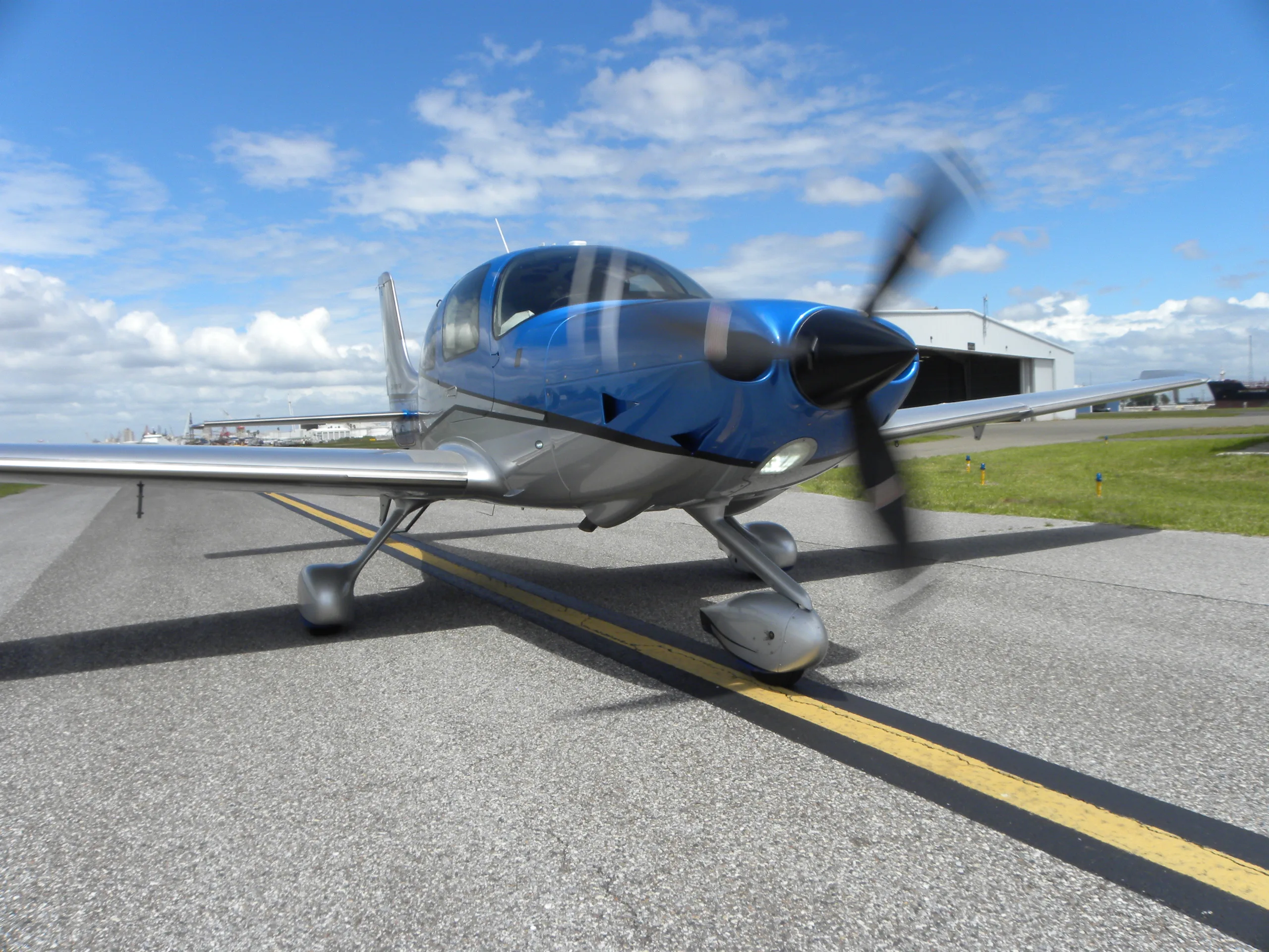

Free — save the SR22T G6 to your watchlist and track it in one place.
More Cirrus SR22T G6manuals & documents
See all 29 →- AVIATION SERVICE DOCUMENT NOTIFICATIONMaintenance Manual
- AAIB Bulletin: 5/2025Service Bulletins
- Airworthiness Directive Schedule Aeroplanes Cirrus SR20 and SR22Service Bulletins
- Airworthiness Directives for Cirrus SR22T G6Airworthiness Directives
- CIRRUS AIRCRAFT SR22T GTS G6Specifications
- 2022 G6 Cirrus SR22TSpecifications
- Cirrus SR2x Prebuy Examination—Scope and DetailChecklist
- INSTRUCTION – HEATER INSTALLATIONWiring Diagram
- CTC Operating Procedures and GuidelinesAirworthiness Directives
- 2021 Cirrus SR22T G6 GTSSystems Description
- PILOT’S OPERATING HANDBOOK AND FAA APPROVED AIRPLANE FLIGHT MANUAL for the CIRRUS DESIGN SR22Pilot's Operating Handbook
- SR22TSpecifications
If you fly the Cirrus SR22T G6, you may also be researching these.



In this document
Introduction
The BlueMAX module is designed to capture serial data from an RS232 data feed and stream it via Bluetooth Low Energy to portable devices. This allows for the display and logging of supplementary aircraft data, such as engine and GPS data. It is important to note that the BlueMAX module is intended to supplement, not replace, the aircraft's primary engine instruments.
Specifications
The BlueMAX module measures 55.2 x 52 x 19 mm and weighs less than 100 g when installed. It operates on a supply voltage of 7-35 V DC, with a maximum current draw of 10 mA and an average of 2 mA. The module uses Bluetooth Low Energy for data transmission at a peak power of 4 dBM (2.5 mW).
Power Requirements
The BlueMAX module requires a maximum of 10 mA of power, which can be supplied from existing breakers. For non-RDM aircraft, it is recommended to use the convenience power breaker CB638 (5A or 3A depending on configuration). For RDM aircraft, power is supplied through the existing wiring harness.
Installation Procedure
The installation of the BlueMAX module should be performed by an FAA certificated Airframe & Powerplant mechanic. The manual provides detailed steps for installation, including tools required and specific procedures for different aircraft configurations. It emphasizes the importance of following AC 43.13-1B for all wiring.
Post Install Checks
After installation, it is crucial to perform checks on the aircraft instruments to ensure proper functionality of the BlueMAX module. This includes verifying the presence of primary engine data on the PFD and ensuring that all connections are secure.
Safety notes
- The BlueMAX module is intended to supplement, not replace, primary engine instruments. Pilots should rely on primary instruments in case of conflicting data.
Full document text
Installation Manual Document Number 2456-05 Revision 14 Date: 2024-10-03 FlightData 2975 Bluegrass Ln. Suite 322 Henderson NV, 89074 © 2021 FlightData Solutions, LLC. All Rights Reserved Table 1. Revision History of 2 53 Date Revision Document Changes 2017-02-17 1 Initial Draft 2017-02-17 2 Revised document list 2017-02-22 3 Placard CB; Flight manual supplement 2017-02-22 4 Minor corrections to wiring instructions 2017-06-07 5 Additional information on wiring and connector identification. 2020-04-11 6 Added JPI and ARNAV, tank selector sensor installation. 2020-06-13 7 Expanded JPI information 2020-12-24 8 Minor corrections and updates 2021-01-02 9 Additional information related to GPS connection 2021-04-12 10 Added RDM installation instructions and minor updates 2021-04-19 11 Minor corrections and updates 2021-07-01 12 Added sample logbook entries, installation approval info, and minor updates/corrections. 2021-07-20 13 Minor corrections and updates 2024-10-03 14 Added compatible JPI units Table of Contents Table of Contents 3 ..................................................................................................... 1. Introduction 5 ..................................................................................................... 1.1 The BlueMAX module 5 ............................................................................................ 1.2 Applicability 5 ............................................................................................................ 1.3 Installation Approval 6 ............................................................................................. 2. Definitions 7 ......................................................................................................... 3. Specifications 8 ................................................................................................... 4. Supporting Documents 9 .................................................................................... 5. Power Requirements 10 ...................................................................................... 5.1 Non RDM Aircraft 10 ................................................................................................ 5.2 RDM Aircraft 10 ........................................................................................................ 6. Preparation for Installation 10 ............................................................................ 6.1 Aircraft Identification 10 .......................................................................................... 6.2 Cirrus Connector Identification (Non RDM) 11 ...................................................... 6.2.1 GPS Connections 11 ............................................................................................. 6.2.2 DAU Connections 11 ............................................................................................. 6.2.3 ARNAV Cirrus Connections 12 ............................................................................. 6.3 Cirrus Perspective Connector Identification (RDM) 12 ......................................... 6.4 Piper and Colombia 13 ............................................................................................. 6.5 Verifying Presence of SIU 13 ................................................................................... 6.5.1 Missing connectors in SIU aircraft 13 ................................................................. 6.6. Verify primary engine data on PFD for DAU aircraft 13 ....................................... 6.7. Installation with MFD permanently removed (Non RDM Aircraft) 15 .................. 6.8. GPS wiring (Non RDM Aircraft) 15 ......................................................................... 7. Parts required 16 ................................................................................................. 8. Installation procedure 17 .................................................................................... 8.1. Tools required 17 ..................................................................................................... 8.2. ARNAV aircraft - MFD permanently removed: 17 ................................................. 8.3. ARNAV aircraft – with MFD fitted: 18 ..................................................................... 8.4. SIU aircraft - MFD has been permanently removed: 19 ....................................... 8.5. SIU aircraft – with MFD fitted: 20 ........................................................................... 8.6. DAU G2 Aircraft: 21 ................................................................................................. 8.7. DAU G3 (Avidyne) Aircraft: 22 ................................................................................. 8.8. Cirrus RDM Aircraft: 23 ........................................................................................... 8.9. JPI Aircraft: 24 ......................................................................................................... 8.9.1. JPI Configuration 24 ............................................................................................. of 3 53 9. Optional Tank Selector Sensor Installation (Non RDM) 25 .............................. 9.1. Cable routing 26 ...................................................................................................... 9.2. Magnet and switch installation 27 ......................................................................... 9.3. Upgrading existing installation with tank selector sensor 29 ............................. 9.3.1. DAU G3 adapter harness 29 ................................................................................ 9.3.2. SIU and DAU G2 adapter harnesses 29 ..............................................................
Show full textShow less
10. Post install checks 30 ....................................................................................... 10.1. Aircraft Instrument Checks (Non RDM) 30 .......................................................... 10.2. App Installation 31 ................................................................................................. 10.3. Connection 31 ........................................................................................................ 10.4. Firmware upgrade 32 ............................................................................................ 10.5. Configuration 33 .................................................................................................... 10.5.1. ARNAV Configuration notes 35 ......................................................................... 10.6 Enabling Automatic Connection to the BlueMAX Module 35 ............................. 10.6.1 Enabling Location Services (iOS Users only) 36 ............................................... 11. Weight and balance 37 ...................................................................................... 12. Flight Manual Supplement 37 ........................................................................... 13. Logbook entry 37 ............................................................................................... 14. Instructions for continued airworthiness 39 ................................................... 15. Removal of the BlueMAX installation 39 ......................................................... 16. Technical support 39 ......................................................................................... 17. Warranty information and Limitations of Liability 39 ..................................... Appendix A: Troubleshooting 40 ............................................................................ A.1. Status icons 40 ........................................................................................................ A.2. Bluetooth Connection Issues 40 ............................................................................ A.3. Bluetooth connects, but no engine data is displayed 42 .................................... A.4. Bug reports 44 ......................................................................................................... Appendix B: Noise Detection 45 ............................................................................. B.1. Noise margin 45 ...................................................................................................... Appendix C: Additional Documentation 46 ........................................................... C.1. Drawing 2530-24: BlueMAX Installation - ARNAV 46 ........................................... C.2. Drawing 2530-09: BlueMAX Installation - SIU 47 ................................................. C.3. Drawing 2530-10: BlueMAX Installation - DAU G2 48 ......................................... C.4. Drawing 2530-12: BlueMAX Installation - DAU G3 49 ......................................... C.5. Drawing 2530-23: BlueMAX Installation - ARNAV (MFD Removed) 50 .............. C.6. Drawing 2530-13: BlueMAX Installation - SIU (MFD Removed) 51 .................... C.7. Drawing 2530-25: BlueMAX Installation - RDM 52 .............................................. C.8. Drawing 2530-18: BlueMAX Installation - JPI 53 ................................................. of 4 53 1. Introduction 1.1 The BlueMAX module The BlueMAX module captures serial data from an RS232 data feed and streams it via Bluetooth Low Energy to portable devices. This enables supplementary aircraft data (such as engine & GPS data) to be displayed and logged on a portable device. WARNING: BlueMAX is intended to supplement and not replace the aircraft’s primary engine instruments. If there is conflicting data between BlueMAX and any primary instruments, the Pilot in Command should rely upon the aircraft’s primary instruments. 1.2 Applicability The BlueMAX module is intended for installation into aircraft already fitted with a compatible engine monitoring system. A list of compatible monitors is given in Table 2. This document focuses on installation in Cirrus SR series aircraft (SR20, SR22, SR22TN and SR22T) generation 1 through generation 5. This includes aircraft equipped with ARNAV/Sagem engine monitors, Avidyne engine monitors, and aircraft with Garmin Perspective avionics. Installation in other aircraft for which specific information is not included here but which have a compatible monitor should be performed in accordance with the same general principles. If there are any issues not covered in this document or accompanying documents contact FlightData for assistance. Table 2. Compatible Engine Monitors Manufacturer Monitor Type Avidyne SIU / DAU ARNAV EMM35 JPI EDM 730/740/830/900/930/960 series monitors with FDR option Heads Up Technologies RDM of 5 53 1.3 Installation Approval Installation of BlueMAX has been approved by EASA by Minor Change Approval 10076563 (available at Flightdata.com/BlueMAX) which directly covers all countries in the EASA regulatory structure. This also means it can be installed in other countries that have bilateral agreements with EASA, including Australia, the USA and Canada. The references for this reciprocal acceptance are: Australia: CASR 1998 regulation 21.470 applies. Refer also to CASA AC 21-08, paragraph 5.23 which covers recognition of foreign approvals. The BlueMAX EASA approval meets all the criteria specified. USA: The BlueMAX installation is a minor change as classified by 14 CFR 21.93(a). AC 43-210A paragraph 3.2.2.1 confirms that an authorized person can perform a minor change with acceptable data, documented by a logbook entry. The EASA approval both provides evidence ("acceptable data") that it is a minor change , and is also considered approved by the FAA per the FAA/EASA Technical Implementation Procedures for Airworthiness and Environmental Certification, paragraph 3.2.2 and 3.3.2. Canada: The Technical Implementation Procedures for Airworthiness and Environmental Certification paragraph 2.13.2(2) provides that a minor change approved by EASA is considered to be approved by Transport Canada Civil Aviation. Other countries may also accept EASA approval under a bilateral agreement. of 6 53 2. Definitions The following abbreviations and acronyms are used in this document: AMM The Cirrus Aircraft Maintenance Manual (See Table 5). BLE Bluetooth Low Energy - the radio protocol used by the BlueMAX module, operating at 2.4GHz. DAU Data Acquisition Unit – One of the two interface modules used by Avidyne to collect analog engine data and convert to RS-232 serial data. DAU’s are found on later serial number Cirrus aircraft that are equipped with Avidyne Entegra avionics. DAU’s are also found on some models of Piper and Columbia aircraft that are equipped with Avidyne avionics. Refer to section 6 and Table 6 for more information. DTU Data Transfer Unit – a module installed in G3 aircraft which collects aircraft data and transmits it to a logging module. EMAX Avidyne’s product name for the engine monitoring system. EX5000 The Avidyne MFD installed in Cirrus SR22 and SR20 aircraft. MFD Multi Function Display – a panel-mounted display used to display non-flight- critical data, including supplementary engine data. PFD Primary Flight Display – a panel mounted display for flight-critical information. RDM Recoverable Data Module - a data storage unit installed in Cirrus SR series aircraft (Generation 3 and later). RS-232 A serial data format used for low-speed communication between electronic devices. SIU Sensor Interface Unit – One of two interface modules used by Avidyne to collect analog engine data and convert to RS-232 serial data. SIU’s are found on earlier serial number Cirrus aircraft that are equipped with Avidyne Entegra avionics (later serial number aircraft will be equipped with a DAU). Refer to section 6 and Table 6 for more information. of 7 53 3. Specifications Table 3. Specifications Table 4. Pinout Size (module only) 55.2 x 52 x 19mm Weight (installed, including adapter harness) Less than 100g Supply Voltage 7-35 V DC Current Maximum: 10mA; Average: 2mA Transmission protocol Bluetooth Low Energy (2.4GHz) Transmission power (peak) 4 dBM (2.5 mW) Pin no. Function 1 Ground, internally connected to pin 6 2 RS232 out - may provide fuel flow/used data 3 RS232 in - GPS data in 4 RS232 out - unused 5 RS232 in - Engine data 6 Ground, internally connected to pin 1 7 GPIO input/output, used for tank selector sensor 8 Power supply +ve of 8 53 4. Supporting Documents Other documents referred to in these instructions are listed in Table 5. Table 5. Referenced Documents Title Document number Rev Date Internal documents Drawing - BlueMAX SIU Adapter Harness 2530-07 5 2020-06-30 Drawing - BlueMAX SIU Basic Adapter Harness (MFD removed) 2530-06 2 2017-02-20 Drawing - BlueMAX DAU G2 Adapter Harness 2530-08 3 2017-06-06 Drawing - BlueMAX DAU G3 Adapter Harness 2530-11 6 2020-11-04 Drawing - BlueMAX ARNAV Adapter Harness 2530-20 1 2019-10-03 Drawing - BlueMAX ARNAV Basic Adapter Harness (MFD removed) 2530-19 3 2019-10-03 Drawing - BlueMAX Bare Adapter Harness 2530-21 2 2020-03-26 Drawing - BlueMAX RDM Adapter Harness 2530-22 2 2021-04-12 Drawing - Cirrus J719-P719 Wiring 2530-17 2 2019-05-16 Drawing - BlueMAX installation – SIU 2530-09 2 2019-05-10 Drawing - BlueMAX installation – DAU G2 2530-10 1 2017-02-15 Drawing - BlueMAX installation – DAU G3 2530-12 1 2017-02-16 Drawing - BlueMAX installation - SIU (MFD removed) 2530-13 1 2017-02-17 Drawing - BlueMAX installation - ARNAV (MFD removed) 2530-23 1 2021-04-12 Drawing - BlueMAX installation - ARNAV 2530-24 1 2021-04-12 Drawing - BlueMAX installation - RDM 2530-25 1 2021-04-12 Drawing - BlueMAX module – circuit 2530-16 3 2017-02-22 Drawing - BlueMAX module - mechanical 2530-01 2 2017-02-22 Drawing - BlueMAX installation JPI 2530-18 3 2019-10-05 Approval - EASA Minor Change Approval 10076563 1 2021-06-27 Manual - BlueMAX Cirrus SOP Supplement 2456-08 3 2021-04-06 External documents ACCEPTABLE METHODS TECHNIQUES, AND PRACTICES - AIRCRAFT INSPECTION AND REPAIR AC 43.13-1B 1 1998-09-08 AIRPLANE WIRING MANUAL FOR THE CIRRUS SR22 AND SR22T 13775-001 D6 2018-09-04 AIRPLANE WIRING MANUAL FOR THE CIRRUS SR20 12129-001 C7 2018-09-04 AIRPLANE MAINTENANCE MANUAL CIRRUS SR22 AND SR22T 13773-001 B8 2018-09-04 AIRPLANE MAINTENANCE MANUAL FOR THE CIRRUS SR20 12137-001 B9 2017-09-04 of 9 53 5. Power Requirements The BlueMAX module draws a maximum of only 10mA and may be supplied from an existing breaker. 5.1 Non RDM Aircraft It is recommended that power be supplied from the convenience power breaker CB638 (5A or 3A depending on aircraft configuration) on the non-essential bus. All power wiring to the BlueMAX module should be 22AWG, which is rated to 5A per AC 43.13-1B, or heavier. 5.2 RDM Aircraft The RDM wiring harness includes power from the 3-amp FUEL QTY circuit breaker on the Main Bus 1 via its wiring harness, so separate power wiring is not required. 6. Preparation for Installation 6.1 Aircraft Identification BlueMAX instillation procedures vary by the avionics configuration. The first step is to identify the aircraft’s applicable configuration: ARNAV monitoring systems were fitted to early production G1 SR20 and SR22 aircraft. Some of those have since been retrofitted with Avidyne SIU monitors. Avidyne EMAX engine monitoring systems installed in Cirrus aircraft fall into two general categories – those fitted with an SIU or those fitted with a DAU: SIUs are fitted only to early serial numbers and can be identified by the presence of analog engine instruments on the right hand side of the instrument panel. Note that for aircraft with the analog engine instruments, the SIU was an option, and may not be fitted to all applicable aircraft. DAUs are fitted to later serial number Avidyne equipped aircraft and can be identified by the presence of a glove box on the right hand side of the instrument panel in lieu of analog engine instruments. The DAU provides two RS-232 outputs, one feeds the MFD and is used for connection to the BlueMAX module, and the other feeds the PFD which displays the primary engine instrumentation. RDM data storage units were installed in Cirrus Perspective aircraft. RS-232 outputs from the aircraft avionics and electrical power are bundled and sent to the unit installed in the aircraft tail. of 10 53 6.2 Cirrus Connector Identification (Non RDM) Connectors installed by Cirrus are generally well labeled, but note that there is a peculiarity with the nomenclature used – connectors with male pins (which would normally be called “plugs”) are called jacks and labeled as Jnnn and connectors with female pins (which would normally be called “sockets” or “jacks”) are called plugs and labeled as Pnnn. 6.2.1 GPS Connections If connection is to be made to GPS data from the #1 GPS on wire ANGP543-22, this is located in J518 (most aircraft) or J517 (serial numbers 22-0434 and earlier, and 20-1336 and earlier.) Refer to the Cirrus wiring manual for further information. J518 carries RS-232 GPS #1 (wire ANGP543-22) data on pin 9 . J518 is a D-Sub plug (i.e. male pins) which connects to P518, which is mounted on the top right of the radio rack, below the MFD opening. J518 is secured by a slide-lock so is relatively easy to remove, but there may be other cables in the way that will have to be disconnected to access it. 6.2.2 DAU Connections DAU G3: P1047 and J1047 are present in G3 aircraft only, and are located forward of the MFD. They use metal backshells with slide-lock coupling. All DAU (G2 & G3): P1426 and J1426 are located in the same area, and are found in all DAU aircraft. They have plastic backshells and jackscrew coupling. See Figure 1 for more detail. Both pairs of connectors are unplugged from each other in this image. There may be variations in the hardware in different aircraft, but all should be labeled – verify identification by checking the labels. of 11 53 Figure 1. Connector locations for Avidyne equipped Cirrus 6.2.3 ARNAV Cirrus Connections ARNAV EMM35 engine monitor units were fitted to a number of early production SR20 and SR22 aircraft. There is one or more pairs of DB9 connectors on the MFD harness where the connection to the EMM35 is made. One of these will be P5A and J5A which will be used to connect the BlueMAX ARNAV adapter harness. These units were installed aftermarket and as a result, wiring and labeling may vary. See Figure 2. Figure 2. Connectors for ARNAV EMM35 6.3 Cirrus Perspective Connector Identification (RDM) P1048 and J1048 are located inside access hole RE2 located on the right side of the empennage below the horizontal stabilizer. See Figure 3 Figure 3. Connectors for Cirrus Perspective RDM of 12 53 6.4 Piper and Colombia Avidyne DAU monitors are fitted to some models of Piper and Columbia aircraft. Installation in these aircraft will be similar to Cirrus DAU installations, but the appropriate wiring manual should be consulted for connector and wire locations. 6.5 Verifying Presence of SIU If the aircraft is fitted with analog engine instruments as shown in Figure 4, confirm the presence of an SIU either by verifying that the MFD displays engine data on the Engine page, or visually confirm the presence of an SIU mounted on the co-pilot side kick panel (below the analog engine instruments.) Refer to the Cirrus AMM chapter 77-40. If the aircraft has analog engine instruments and no SIU the BlueMAX module cannot be installed. 6.5.1 Missing connectors in SIU aircraft The SIU serial data is connected from the SIU to the MFD by cable ANMD977-22 (refer to Cirrus Wiring Manual chapter 77-00-01) and in SR22s with serial numbers 1087 and above, and SR20s with serial numbers 1456 and above, this cable incorporates a pair of connectors labelled J719/ P719 which provides a convenient place to insert the adapter harness p/n 4370-5147. Aircraft with serial numbers below those ranges may not have J719/P719 fitted and installation of BlueMAX will be facilitated if those connectors are installed in accordance with the Cirrus Wiring Manual chapter 77-00-01. The necessary connectors can be ordered from FlightData as part number 4370-9869 and drawing 2530-17 provides additional guidance. 6.6. Verify primary engine data on PFD for DAU aircraft DAU equipped aircraft display primary engine data on the PFD, but this requires that the software version installed on the PFD supports this display. To verify this, power up the aircraft and inspect the lower right area of the PFD. There should be a data block with primary engine data as shown in Figure 5. If this data is absent, the PFD software must be upgraded before installing BlueMAX. The applicable aircraft models, serial numbers and configurations are summarized in Table 6: Cirrus Engine monitor types. of 13 53 Figure 4. Analog engine instruments Figure 5. Engine data on PFD Table 6. Cirrus Engine monitor types Model Serial numbers Installation Type Notes G1/G2 SR20 1005 - 1581 Cirrus SIU SIU must be fitted. G2 SR20 1582 - 1877, 1879 - 1885 Cirrus DAU G2 Verify primary engine data displayed on PFD G3 SR20 (with Avidyne Avionics) 1878, 1886 - 2015 Cirrus DAU G3 Verify primary engine data displayed on PFD G3/G5 SR20 (with Garmin Perspective Avionics 2016 - 2392 Cirrus RDM Does not include G6 G1/G2 SR22 0002 - 1601, 1603 -1643 and 1645 - 1662 Cirrus SIU SIU must be fitted. G2 SR22 1602, 1644, 1663 - 2333, 2335 - 2419, 2421 -2437 Cirrus DAU G2 Verify primary engine data displayed on PFD G3 SR22 (with Avidyne Avionics) 2334, 2420, 2438 -2978, 2980 - 2991, 2993 -3001, 3003 - 3025 Cirrus DAU G3 Verify primary engine data displayed on PFD G3-G5 SR22 (with Garmin Perspective Avionics 2979, 2992, 3002, 3026 - 4593 Cirrus RDM Does not include G6 G3-G5 SR22T 0001-1691 Cirrus RDM Does not include G6 of 14 53 6.7. Installation with MFD permanently removed (Non RDM Aircraft) If the MFD has been permanently removed from the aircraft, an alternative installation method is to connect the BlueMAX module to the now unused MFD connector. This connector is shown in the Cirrus Wiring Manual as P528. This provides serial engine data, serial GPS data (SIU aircraft only) and power in a single connector. The SIU Basic adapter harness p/n 4370-9630 is available to plug directly into P528. Installation in DAU G2 equipped aircraft where the MFD is to be removed will require a separate wire for the GPS connection as it was not wired to the MFD in those aircraft. Installations in DAU G3 aircraft should use the DAU G3 harness in any case as it provides engine and GPS data in one. 6.8. GPS wiring (Non RDM Aircraft) For full functionality the BlueMAX module requires a GPS data feed to capture GPS position, speed, and altitude. For this purpose, BlueMAX ARNAV and Avidyne wiring harnesses (with the exception of the DAU G3) come with a GPS wire for connection to the RS232 output from a GPS navigator (typically a GNS430 or similar). For more information on identifying GPS connections, refer to section 6.2.1 above. Cirrus SIU aircraft that are equipped with an Avidyne EX5000C MFD have an RS-232 connection from one of the GPS units to the MFD (which is not used by the MFD). The RS232 connection from the GPS to the MFD on these aircraft may be disconnected to facilitate connection to the BlueMAX module. Note: Accessing this wire (ANGP543-22) at the connection to the MFD is easier than at the connector on top of the radio stack. Refer to drawing 2530-09 for more details. Notes: 1) For Cirrus SRV aircraft fitted with EX3000 MFDs: The RS-232 connection from GPS to MFD on EX3000 MFD equipped aircraft is required and cannot be disconnected. The RS232 connection to an EX3000 can still be used by the BlueMAX, but it will require a wire to be spliced onto this connection so that the feed to the MFD remains intact. 2) RS-232 wires are shielded. To avoid compromising the wire shield, wire splice must be done at a wire termination. To avoid a ground loop, do not connect the shields together (the shield is grounded at the BlueMAX module end.) Cirrus DAU G2 aircraft do not have an RS-232 connection from the GPS to the MFD and will require a separate wire for the GPS connection to the BlueMAX module. Cirrus DAU G3 (Avidyne) wiring harnesses provide engine and GPS data in one, so separate GPS wiring is not required. of 15 53 7. Parts required Installation of BlueMAX requires the BlueMAX module, an adapter harness which connects it to the aircraft wiring, and two BlueMAX window stickers. The adapter harnesses for ARNAV, SIU, DAU and RDM aircraft are different – order the correct parts as listed in Table 7. For installation with JPI engine monitors, or for installation in aircraft other than SR20 and SR22, use the bare adapter harness. This has the BlueMAX connector with power, ground and data cables provided but unterminated. For RDM installation, Loctite 5140 and a 3/8 inch horsehair acid brush will be required for sealing connectors. For all installations, there may be cable ties, wire, splices and other common electrical parts required – these are not included in the kit. Table 7. BlueMAX part numbers Installation type BlueMAX module Adapter Harness Harness w/tank sensor Cirrus ARNAV 4370-2730 4370-8345 4370-8346 Cirrus ARNAV (MFD removed) 4370-2730 4370-6148 4370-6149 Cirrus SIU 4370-2730 4370-5146 4370-5147 Cirrus SIU (MFD removed) 4370-2730 4370-9630 4370-9631 Cirrus DAU G2 4370-2730 4370-2720 4370-2721 Cirrus DAU G3 4370-2730 4370-8434 4370-8435 Cirrus RDM 4370-2730 4370-9652 NA Other aircraft - Bare harness 4370-2730 4370-7142 4370-7143 of 16 53 8. Installation procedure The BlueMAX installation falls outside the scope of owner-authorized Preventative Maintenance (per 14 CFR Appendix A to part 43 Subpart c) and should be installed by an FAA certificated Airframe & Powerplant mechanic (or international equivalent) in accordance with one of the following procedures. All wiring should be performed in accordance with AC 43.13-1B. 8.1. Tools required An iOS device (i.e. iPad / iPhone) or Android device will be required post installation to verify proper BlueMAX operation. 8.2. ARNAV aircraft - MFD permanently removed: Harness p/n 4370-6149 (different from ARNAV install with MFD) Note: Installation drawing can be found in Appendix C below 1. Gain access behind the instrument panel through the opening where the MFD was previously fitted. Note: if installing an adapter harness that has the optional tank selector cable and you do not wish to install the tank selector sensor, cut the fuel selector wire at the base of the BlueMAX connector and continue the installation process as detailed below. 2. If the tank selector sensor is being fitted refer to Section 9 and install the tank selector sensor in accordance with those instructions. Note: The power wire will be routed with the optional tank selector cable. More details on “best practices” for the cable and power wire routing can be found in Section 9.1 and Figure 7 below. 3. Route the power wire in the ARNAV adapter harness to the circuit breaker panel and terminate to the convenience power breaker currently labeled “12VDC OUTLET”. Relabel the breaker “12VDC OUTLET/BLUETOOTH”. 4. Plug ARNAV Basic adapter harness into the MFD connector J5A and secure with cable ties or screws. Note: If you do not wish to connect GPS data, cap and stow the shielded cable, or remove from the BlueMAX connector. CAUTION: 1.To avoid compromising the wire shield, wire splice must be done at a wire termination. 2. To avoid a ground loop, do not connect the shields together (the shield is grounded at the BlueMAX module end.) of 17 53 5. To connect GPS data to the BlueMAX module, locate wire ANGP543-22 which runs from GPS1 to the MFD (found on J517) and splice the signal wire to the inner of the shielded wire provided in the adapter harness. 6. Plug the BlueMAX module into the other end of the adapter harness. 7. Secure module & cabling to existing structure or wire bundles using cable ties. 8. Perform Operational Test - Engine and Electrical Indication Systems IAW Cirrus the AMM. 9. Place BlueMAX stickers in the lower left corners of the two aft passenger windows as depicted here: 8.3. ARNAV aircraft – with MFD fitted: Harness p/n 4730-8346 (different from ARNAV install with MFD removed) Note: 1) ARNAV EMM35 units were installed aftermarket and wiring can vary. 2) Installation drawing can be found in Appendix C below 1. Remove MFD to gain access behind the instrument panel. Note: if installing an adapter harness that has the optional tank selector cable and you do not wish to install the tank selector sensor, cut the fuel selector wire at the base of the BlueMAX connector and continue the installation process as detailed below. 2. If the tank selector sensor is being fitted refer to Section 9 and install the tank selector sensor in accordance with those instructions. Note: The power wire will be routed with the optional tank selector cable. More details on “best practices” for the cable and power wire routing can be found in Section 9.1 and Figure 7 below. 3. Route the power wire in the ARNAV adapter harness to the circuit breaker panel and terminate to the convenience power breaker currently labeled “12VDC OUTLET”. Relabel the breaker “12VDC OUTLET/BLUETOOTH”. 4. Locate connector pair P5A/J5A. They will be one of the DB9 connectors on the harness that connects the EMM35 engine monitor to the MDF. For more information, see section 6.2.3 above. Note: only one of the DB9 connectors will contain P5A and J5A, so you may have to try both. Secure using cable ties or screws. 5. Disconnect P5A and J5A connectors from each other and re-connect to the ARNAV adapter harness. of 18 53 Note: If you do not wish to connect GPS data, cap and stow the shielded cable, or remove from the BlueMAX connector. CAUTION: 1.To avoid compromising the wire shield, wire splice must be done at a wire termination. 2. To avoid a ground loop, do not connect the shields together (the shield is grounded at the BlueMAX module end.) 6. To connect GPS data to the BlueMAX module, locate wire ANGP543-22 which runs from GPS1 to the MFD (found on J517) and splice the signal wire to the inner of the shielded wire provided in the adapter harness. Plug the BlueMAX module into the other end of the adapter harness. 7. Secure module & cabling to existing structure or wire bundles using cable ties. 8. Replace MFD IAW the Cirrus AMM. 9. Perform Operational Test - Engine and Electrical Indication Systems IAW the Cirrus AMM. 10. Place BlueMAX stickers in the lower left corners of the two aft passenger windows as depicted here: 8.4. SIU aircraft - MFD has been permanently removed: Harness p/n 4370-9631 (different from SIU install with MFD) Note: Installation drawing can be found in Appendix C below 1. Gain access behind the instrument panel through the opening where the MFD was previously fitted. Note: if installing an adapter harness that has the optional tank selector cable and you do not wish to install the tank selector sensor, cut the fuel selector wire at the base of the BlueMAX connector and continue the installation process as detailed below. 2. If the tank selector sensor is being fitted refer to Section 9 and install the tank selector sensor in accordance with those instructions. 3. Plug SIU Basic adapter harness into the MFD connector P528. 4. Plug the BlueMAX module into the other end of the adapter harness. 5. Secure module & cabling to existing structure or wire bundles using cable ties. 6. Perform Operational Test - Engine and Electrical Indication Systems IAW the Cirrus AMM. 7. Place BlueMAX stickers in the lower left corners of the two aft passenger windows as depicted here: of 19 53 8.5. SIU aircraft – with MFD fitted: Harness p/n 4370-5147 (different from SIU install with MFD removed) Note: Installation drawing can be found in Appendix C below 1. Remove MFD to gain access behind the instrument panel. Note: if installing an adapter harness that has the optional tank selector cable and you do not wish to install the tank selector sensor, cut the fuel selector wire at the base of the BlueMAX connector and continue the installation process as detailed below. 2. If the tank selector sensor is being fitted refer to Section 9 and install the tank selector sensor in accordance with those instructions. Note: The power wire will be routed with the optional tank selector cable. More details on “best practices” for the cable and power wire routing can be found in Section 9.1 and Figure 7 below. 3. Route the power wire in the SIU adapter harness to the circuit breaker panel and terminate to the convenience power breaker currently labeled “12VDC OUTLET”. Relabel the breaker “12VDC OUTLET/BLUETOOTH”. 4. Locate connector pair P719/J719. If these are not fitted locate wire ANMD977-22 running from the SIU to the MFD, and install P719 and J719 in accordance with the Cirrus Wiring Manual. FlightData drawing 2530-17 is available for guidance on the connector wiring. 5. Disconnect P719 and J719 from each other and re-connect to the SIU adapter harness. Note: If you do not wish to connect GPS data, cap and stow the shielded cable, or remove from the BlueMAX connector CAUTION: 1.To avoid compromising the wire shield, wire splice must be done at a wire termination. 2. To avoid a ground loop, do not connect the shields together (the shield is grounded at the BlueMAX module end.) 6. To connect GPS data to the BlueMAX module: -EX5000C MFDs: locate wire ANGP543-22 which runs from GPS1 to the MFD (found on J517 or J518 depending on serial number). The MFD receives GPS data via ARINC429 and thus the RS232 connection from the GPS is not used by the MFD. Disconnect ANGP543-22 from the MFD and splice the signal wire to the inner of the shielded wire provided in the adapter harness. For more information refer to section 6.7 above. of 20 53 -EX3000 MFDs MFDs (SRV models): Locate wire ANGP543-22 which runs from GPS1 to the MFD (found on J517 or J518 depending on serial number) and splice the signal wire to the inner of the shielded wire provided in the adapter harness. 7. Plug the BlueMAX module into the other end of the adapter harness. 8. Secure module & cabling to existing structure or wire bundles using cable ties. 9. Replace MFD IAW the Cirrus AMM. 10. Perform Operational Test - Engine and Electrical Indication Systems IAW the Cirrus AMM. 11. Place BlueMAX stickers in the lower left corners of the two aft passenger windows as depicted here: 8.6. DAU G2 Aircraft: Harness p/n 4370-2721 Note: Installation drawing can be found in Appendix C below 1. Remove MFD to gain access behind the instrument panel. Note: if installing an adapter harness that has the optional tank selector cable and you do not wish to install the tank selector sensor, cut the fuel selector wire at the base of the BlueMAX connector and continue the installation process as detailed below. 2. If the tank selector sensor is being fitted refer to Section 9 and install the tank selector sensor in accordance with those instructions. Note: The power wire will be routed with the optional tank selector cable. More details on “best practices” for the cable and power wire routing can be found in Section 9.1 and Figure 7 below. 3. Route the power wire in the DAU G2 adapter harness to the circuit breaker panel and terminate to the convenience power breaker currently labeled “12VDC OUTLET”. Relabel the breaker “12VDC OUTLET/BLUETOOTH”. 4. Locate connector pair P1426/J1426. These will be directly behind the MFD. 5. Disconnect P1426 and J4126 from each other and re-connect to the DAU G2 adapter harness. Note: If you do not wish to connect GPS data, cap and stow the shielded cable, or remove from the BlueMAX connector. of 21 53 6. To connect GPS data to the BlueMAX module, locate connector pair P518/J518 (at the top right of the radio rack) disconnect, and remove the backshell from J518. Pin 9 in J518 should be empty. 7. The adapter harness has a shielded wire attached terminated with a pre- crimped male pin. Insert this pin into J518 in the pin 9 position. 8. Replace the backshell on J518, securing all cables. 9. Reconnect J518 to P518. 10. Plug the BlueMAX module into the other end of the adapter harness. 11. Secure module & cabling to existing structure or wire bundles using cable ties. 12. Replace MFD IAW the Cirrus AMM. 13. Perform Operational Test - Engine and Electrical Indication Systems IAW the Cirrus AMM. 14. Place BlueMAX stickers in the lower left corners of the two aft passenger windows as depicted here: 8.7. DAU G3 (Avidyne) Aircraft: Harness p/n 4370-8435 Note: Installation drawing can be found in Appendix C below 1. Remove MFD to gain access behind the instrument panel. Note: if installing an adapter harness that has the optional tank selector cable and you do not wish to install the tank selector sensor, cut the fuel selector wire at the base of the BlueMAX connector and continue the installation process as detailed below. 2. If the tank selector sensor is being fitted refer to Section 9 and install the tank selector sensor in accordance with those instructions. Note: The power wire will be routed with the optional tank selector cable. More details on “best practices” for the cable and power wire routing can be found in Section 9.1 and Figure 7 below. 3. Route the power wire in the DAU G3 adapter harness to the circuit breaker panel and terminate to the convenience power breaker currently labeled “12VDC OUTLET”. Relabel the breaker “12VDC OUTLET/BLUETOOTH”. 4. Locate connector pair P1047/J1047. These will be directly behind the MFD. of 22 53 5. Disconnect P1047 and J1047 from each other and re-connect to the G3 adapter harness. 6. Plug the BlueMAX module into the other end of the adapter harness. 7. Secure module & cabling to existing structure or wire bundles using cable ties. 8. Replace MFD IAW the Cirrus AMM. 9. Perform Operational Test - Engine and Electrical Indication Systems IAW the Cirrus AMM. 10. Place BlueMAX stickers in the lower left corners of the two aft passenger windows as depicted here: 8.8. Cirrus RDM Aircraft: Harness p/n 4370-9652 Note: Installation drawing can be found in Appendix C below 1. Set BAT 1, BAT 2, and AVIONICS switches to OFF positions. 2. Pull FUEL QTY, STALL WARNING, and GPS NAV GIA 1 circuit breakers. 3. Remove access panel RE2 found on the right side of the empennage below the horizontal stabilizer 4. Locate connector pair P1048/J1048 inside the access hole. Disconnect P1048 and J1048 from each other and re-connect to the RDM adapter harness. 5. Temporarily orient and stabilize connectors in a level position inside tail area with open back-shells facing up. Note: Use brush to coat entire inside of back-shell with sealant, including wiring, connector body, walls and ring lug. Ensure small gaps and features between wires and connector are coated. 6. Coat outer surfaces of mated connectors with sealant. 7. Pour sealant into open connector backshells to fill up to top of connector. Allow 24 hours undisturbed to cure. 8. Attach backshell cover plates and brush coat entire outer surface of mated connectors including connector interfaces and cable entries. Allow time to cure. WARNING: Verify no interference exists between RDM cable and flight controls. 9. Plug the BlueMAX module into the other end of the adapter harness. of 23 53 CAUTION: Ensure mated connectors and BlueMAX module are secured along fuselage wall and off BL0 floor. Note: Ensure that the BlueMAX module are secured upright such that connector is facing the aft of the aircraft. This will orient the bluetooth antenna in the most favorable position to connect with a mobile device in the cabin. 10. Secure module, connectors & cabling to existing structure or wire bundles using cable ties ensuring the unit is not in an area where moisture can pool. 11. Reset FUEL QTY, STALL WARNING and GPS NAV GIA 1 circuit breakers. 12. Perform Operational Test - Aircraft Data Logger System IAW the Cirrus AMM 13. Replace access panel RE2. 14. Place BlueMAX stickers in the lower left corners of the two aft passenger windows as depicted here: 8.9. JPI Aircraft: Harness p/n 4370-7143 Note: Installation drawing can be found in Appendix C below BlueMAX will work with any JPI engine monitor supporting FDR or DAU output formats, which includes EDM730, EDM740, EDM830 and EDM9xx series units with FDR capability. Serial data is supplied by the JPI monitor on connector P1, pin 24 at 9600 baud (FDR) or 57600 baud (DAU). See drawing 2530-18 for wiring details. 8.9.1. JPI Configuration The JPI unit must be configured to send data via the serial output. To configure proceed as follows: 1. Hold left two buttons until “PROGRAM” message is displayed. 2. Tap left button (NO) when “REFUEL?” displayed 3. Continue tapping left button until “END?” displayed 4. Tap rightmost button (labeled “FACTORY”) 5. Tap left button repeatedly (many times) until “REMOTE DISPLAY I/O?” is displayed (the program may only display “I/O?” in some versions). 6. Select “MASTER/SLAVE” to enable DAU output at 57600 baud. 7. Continue stepping until the setting "FDR OUTPUT" and set it to Y. This enables FDR output at 9600 baud. of 24 53 9. Optional Tank Selector Sensor Installation (Non RDM) The BlueMAX module can sense the position of the fuel tank selector via a reed switch which is mounted next to the tank selector shaft. A small magnet is glued to the base of the shaft so that it activates the switch when the selector is in the left tank position. There is no physical contact with the tank selector or shaft so no possibility of interference with normal operation of the tank selector. Note: The Tank Selector Sensor is optional. If you do not wish to install the tank elector sensor and you are using a wiring hardness that has the optional tank selector sensor cables, simply cut the fuel secretor wire at the base of the BlueMAX connector and continue the installation process as detailed below Figure 6. Tank sensor installation of 25 53 9.1. Cable routing The tank sensor cable (composed of a white and black wire) must be routed from the module installation location to the tank selector area. Proceed as follows using the AMM for reference. 1. Remove the pilot’s seat. 2. Open the circuit breaker panel. 3. Remove the trim panel surrounding the circuit breaker panel, extending back to the center console area. 4. Route the tank sensor cable (i.e. both black and white wires) and power wire from under the glareshield down to the circuit breaker panel area. This can be quite full of existing wiring - it may be useful to use a length of 12mm semi-rigid plastic tubing as a guide - see Figure 7. Slide the wires down the tubing then remove the tubing. 5. The power wire will be terminated onto a circuit breaker as described above. Route the tank sensor wire above the circuit breaker panel back to the tank selector area. Figure 7. Cable routing of 26 53 9.2. Magnet and switch installation Figure 8. Magnet installation 1. Supplied with the adapter harness is a small rare earth circular magnet. 2. Place this magnet onto a piece of clear adhesive tape. 3. Position the fuel tank selector to the left tank position. 4. Clean the left hand side of the tank selector shaft and the adjacent panel with isopropyl alcohol. 5. Mix a small quantity of 5-minute epoxy and apply to the magnet, ensuring that a thin coat is applied to the exposed top and sides. 6. Position the magnet onto the tank selector shaft so that the magnet is facing the left hand side of the aircraft and is centered 7mm (approx 1/4") above the base horizontal panel - see Figure 8. 7. After the epoxy has cured remove the adhesive tape. 8. Attach the white and black wires from the tank sensor cable to the reed switch. (Polarity does not matter, so the white and black wires can be connected to either side of the reed switch). The reed switch cover should be removed to expose the connector screws. Note: the wire ends do not need to be stripped - the reed switch connectors will puncture the insulation when the screws are tightened. Do not over tighten. of 27 53 9. Replace the cover on the reed switch and mark the top of the switch with a line 19 mm (3/4") from the side of the switch faction toward the nose of the aircraft - the switch will be positioned with the wires facing the left side of the aircraft. See Figure 9 below for orientation. 10. Remove the backing paper from the double sided tape on the bottom of the switch. 11. Position the switch at right angles to the magnet, with the mark on top of the switch adjacent to the magnet. There must be a gap of 1 - 3mm (1/16 - 1/8") between the magnet and the switch. 12. Verify that rotation of the tank selector does not result in any contact between the reed switch and magnet or selector shaft. 13. Press firmly to adhere the double sided tape. Reinforce with a fillet of 5-minute epoxy around the base of the switch. 14. Secure the cable with cable ties as required. See Figure 6 for a view of the completed switch installation. Figure 9. Switch installation of 28 53 9.3. Upgrading existing installation with tank selector sensor Where an existing BlueMAX installation without tank selector sensor is to be upgraded, users can either purchase a new adapter harness or install the additional two wires and reed switch manually. If installing the additional wires, they will need to be attached to the existing BlueMAX adapter harness. Remove the BlueMAX connector from the module and proceed as follows. 9.3.1. DAU G3 adapter harness Open the BlueMAX connector hinge and insert the pins on the tank sensor wire - black wire (ground) into location 1 and the white wire into location 7. Close the connector hinge. 9.3.2. SIU and DAU G2 adapter harnesses The new wire requires connection to the existing ground wire. Both the shield and the black wire in the new cable should be connected to ground at the BlueMAX module. It may be expedient to remove the adapter harness from the aircraft for these steps. Refer to Figure 10 for an illustration of the manner in which the new wire is to be connected to the existing ground wire. 1. Identify the ground wire connected to pin 6 of the BlueMAX connector. Open the BlueMAX connector and remove the pin and wire from location 6. A fine sharp tool will be required to lift the pin retainer. 2. Cut this wire at a point approximately 25mm (1") from the connector. Strip each cut end approximately 3mm (1/8"). 3. The upgrade harness has a two-core shielded wire supplied with a solder sleeve. Insert the shielded wire into the solder sleeve so that the bare shield lies within the solder ring. 4. Insert into the solder sleeve the two ends of the ground wire and the doubled- back black wire from within the tank sensor cable. The stripped ends of all three wires should be positioned with the exposed shield inside the solder ring. 5. Using a heat gun shrink the sleeve and melt the solder ring so that all the wires and the shield are firmly soldered. There should be no visible ring left from the solder. Check for physical security and electrical continuity of the wires. 6. Now insert the ground wire back into location 6 on the BlueMAX connector, and insert the new wire from the tank sensor into location 7. Close the connector. of 29 53 Figure 10. Tank sensor upgrade harness connection. 10. Post install checks WARNING: When powering the aircraft from external power use only an electrically clean power supply at 14V or 28V as required. Turn on the aircraft battery prior to plugging in the external power source to minimize the risk of spikes on the electrical bus. Do not externally power up the aircraft without the aircraft battery fitted! 10.1. Aircraft Instrument Checks (Non RDM) 1. Power up the aircraft and verify that the analog instruments (if fitted) or the PFD display primary engine data. 2. Verify that the MFD (if fitted) displays supplementary engine data. The BlueMAX module requires configuration after installation. This is performed via the BlueMAX app which is available for iOS and Android. The module must be powered up for this process. of 30 53 10.2. App Installation Either use the following URLs or search the App Store (iOS) or Play Store (Android) for "BlueMAX Aircraft Monitor" and install the app on an iPad or Android tablet. 1. iOS - https://apps.apple.com/au/app/bluemax-aircraft-monitor/id1238996807 2. Android - https://play.google.com/store/apps/details?id=com.controlj.bluemax.app 10.3. Connection If the app is freshly installed and has not previously connected to any BlueMAX module it will automatically connect to the first one it finds after it is opened. If it has previously connected to a different module then it will be necessary to find the new module in the Bluetooth page. This is selected via the Bluetooth menu item. The menu can be opened by swiping across from the left hand side of the screen. Note: The BlueMAX module is a BLE device and it will not appear as a Bluetooth device in the iOS Bluetooth settings page. Bluetooth connection to the BlueMAX module is managed exclusively in the BlueMAX app. For troubleshooting help, see section A.2 of the troubleshooting guide below. Figure 11 - BlueMAX app: main menu Figure 12 - BlueMAX app: Bluetooth Management screen of 31 53 10.4. Firmware upgrade Before configuring the BlueMAX module check for a firmware upgrade for the module. CAUTION: Do not attempt to upgrade firmware in flight. Notes: 1) Internet connection required to perform update. 2) The BlueMAX adapter must be powered (turn on aircraft battery) and you will need to be within range of the bluetooth connection There are two ways to do the update. If method one does not work, use method two. Method One: 1. Open the Main menu: Swipe across the screen from the left. 2. Access the Tool menu: Tap the “Tools” button. 3. Now choose "Firmware upgrade". A dialog will appear (see Figure 13 ) and if an upgrade is available will prompt to install it. Tap Update. If no upgrade is available the dialog will disappear with a message "Firmware is up to date.” Method Two (This method can be used if you need to update multiple modules): 1. Open the Main menu: Swipe across the screen from the left. 2. Access the Bluetooth Management page: tap the “Bluetooth” button. 3. In the page that opens find your device (if you only use one, that's all there should be.) If you have previously connected to it the device will be under "Active BlueMAX adapters", otherwise it will be under "New BlueMAX adapters". The page can be refreshed by dragging down. 4. Tap the device name and a menu will pop up. If one of the options is "disconnect" choose that, then tap the device name again. 5. Now choose "Firmware upgrade". A dialog will appear and if an upgrade is available will prompt to install it. Tap Update. If no upgrade is available the dialog will disappear with a message "Firmware is up to date.” After a few seconds it should complete and disconnect. 6. You can now connect to the device by tapping the name again and selecting "Connect". of 32 53 Figure 13 - BlueMAX app: Update firmware pop up menu 10.5. Configuration Note: Configuration should be accomplished when the BlueMAX module is NOT connected to the app. If you are already connected to the device, select the device from the Bluetooth management screen and click “Disconnect” before following the directions below. 1. Tap the device name and select “Configure". The dialog box shown in Figure 14 will appear with various options - see Table 8 for a description of the options. 2. Set the options as appropriate for the installation and tap OK. 3. Tap the device name again and select "Connect". The app will connect to the module and should display engine data. Figure 14 - BlueMAX app: module configuration page of 33 53 Table 8. Configuration Dialog Items Item Function Device Name Allows changing the name of the module. It is recommended to set this to match the aircraft tail number. Interface Selects the serial interface format. See Table 9 for details. COM1 Baudrate Baud rate for the COM 1 (Engine data) interface. Will be set automatically when the interface format is chosen and should only be overridden in special circumstances. COM2 Baudrate Baud rate for the GPS input - leave at 9600 Total Flight Time (hrs) The module will accumulate flight time. This allows setting it to match the aircraft’s current TTIS per the logbook. MP Offset A calibration factor for the Manifold Pressure sensor. The value in this field will be added to the received MP value before display and logging, e.g. if your MP sensor reads 0.5 inHg high, enter -0.5 in this field. Noise Detection Margin See Appendix B for details. Tank selector sensor Check this box if a tank selector sensor is installed. FF K-factor Used only with some engine monitor types and should be the K-factor of the fuel flow sensor. For most Cirrus aircraft this is 29200 but some early SR20s with ARNAV monitors are 33330 Factory CHT cylinder Used only with ARNAV installations, and should be the cylinder which has a CHT probe connected to the analog CHT gauge. This should be #6 in SR22s, and #2 or #3 in SR20s depending on serial number. RPM Factor Used with ARNAV only. If the RPM on the app does not match the RPM on the MFD, calculate the RPM factor: 1. Set the RPM factor to 1 (this removes any adjustment) 2. Run the aircraft and record the RPM indications shown on the BlueMAX and those shown on the ARNAV MFD 3. RPM Factor = BlueMAX RPM divided by ARNAV MFD RPM (For example, if the BlueMAX = 1,500 RPM and the ARNAV indicates 1,000 RPM, then the RPM factor is 1.5) 4. Set the RPM factor per above (in this case 1.5) and run the plane to confirm correct indications. Note: the RPM indication on the ARNAV is sometimes "rounded" so for best results, attempt to adjust the RPM to a round number on both units (i.e. 1,000 RPM and 1,500 RPM) before making adjustments. of 34 53 Table 9. Interface choices 10.5.1. ARNAV Configuration notes 1. The lower limit for many of the parameters that are displayed on the ARNAV MFD are higher than the actual readings for the parameters when the engine is not running. The actual readings are captured by the EMM35 engine monitoring system and transmitted via the BlueMAX module. As such, it is normal for the parameters shows on the BlueMAX app to differ from those displayed on the MFD when the engine is not running. 2. The RPM factor must be calculated using the method shown in Table 8 above. 10.6 Enabling Automatic Connection to the BlueMAX Module The BlueMAX can automatically connect to your mobile device when powered and in range for BLE connection. To enable this feature follow the directions below. Note: Auto connection will not work in “airplane mode”. If using “airplane mode”, the BlueMAX will require manual connection. 1. Open the BlueMAX mobile app. 2. Open the main menu: Swipe across the screen from the left. 3. Select “Settings”. 4. Select the “Auto connect in the background” box. Note: iOS users will also need to modify location services. Refer to section 10.6.1 below for details. Selection Usage DAU Avidyne DAU monitors - 19200 baud SIU Avidyne SIU monitors - 9600 baud DEMO Demo mode - internally generates dummy data AVIATION GPS input only - do not use. ARNAV ARNAV EMM35 - 19200 baud JPI_DAU JPI monitors with DAU format at 57600 baud JPI_FDR JPI monitors with FDR format at 9600 baud RDM Cirrus Perspective equipped aircraft of 35 53 Figure 15 - BlueMAX Setting Menu 10.6.1 Enabling Location Services (iOS Users only) For automatic connection to the BlueMAX module on iOS devices, BlueMAX location services need to be set to “Always”. If location services are set to “While Using the App” you will need to open up the mobile app prior to each flight to initiate the connection to the BlueMAX module. To change the location services option follow these steps: 1. Open Phone Settings. 2. Select “Privacy”. 3. Select “Location Services” at the top. 4. Select “BlueMAX” from the list. 5. Select “Always” from the list of Location Access Options. Note: After you enable this option, you will get notifications from time to time reminding you that location services have been running for BlueMAX and it will ask if you would like to change your location services option. If you change it to “While Using the App” you will lose the automatic connection function. of 36 53 Figure 16 - BlueMAX Location Services Menu 11. Weight and balance The installed weight of the BlueMAX module and adapter harness is approximately 120g (less than 4 ounces) and results in a change in the CG position of approximately 0.008% MAC. This is considered a negligible change per AC 43.13-1B and no weight and balance update is required. 12. Flight Manual Supplement Complete the required information on the provided Flight Manual Supplement and insert it into the aircraft Flight Manual or POH. 13. Logbook entry Make a suitable logbook entry documenting the installation. Sample text below for USA registered aircraft, edit as required for specific installation: For ARNAV installation without MFD: "Installed BlueMAX ARNAV basic adapter harness (p/n 4370-9631) and BlueMAX adapter module (p/n 4370-2730) at connector J5A. Connected adapter harness power wire to convenience power breaker currently labeled “12VDC OUTLET” and relabel the breaker “12VDC OUTLET/BLUETOOTH”. Spliced ANGP543-22 signal wire to BlueMAX inner shielded GPS wire. Attached magnet to fuel tank selector shaft and attached reed switch next to the base of the fuel tank selector tank using 5-minute epoxy. Secured BlueMax adapter module and cabling to existing structure using cable ties. All work IAW AC43.13-1B. Performed operational test of Engine & Electrical Indication Systems IAW Cirrus AMM. No defects noted at this time." For ARNAV installation with MFD: "Removed MFD. Installed BlueMAX ARNAV adapter harness (p/n 4370-8346) and BlueMAX adapter module (p/n 4370-2730) at connector pair P5A/J5A. Connected adapter harness power wire to convenience power breaker currently labeled “12VDC OUTLET” and relabel the breaker “12VDC OUTLET/BLUETOOTH”. Spliced ANGP543-22 signal wire to BlueMAX inner shielded GPS wire at termination into J517. Attached magnet to fuel tank selector shaft and attached reed switch next to the base of the fuel tank selector tank using 5-minute epoxy. Secured BlueMax adapter module and cabling to existing structure using cable ties. Replaced MFD IAW the Cirrus AMM. All work IAW AC43.13-1B. Performed operational test of Engine & Electrical Indication Systems IAW Cirrus AMM. No defects noted at this time." of 37 53 For SIU installation without MFD: "Installed BlueMAX SIU basic adapter harness (p/n 4370-9631) and BlueMAX adapter module (p/n 4370-2730) at connector P528. Connected adapter harness power wire to convenience power breaker currently labeled “12VDC OUTLET” and relabel the breaker “12VDC OUTLET/BLUETOOTH”. Attached magnet to fuel tank selector shaft and attached reed switch next to the base of the fuel tank selector tank using 5-minute epoxy. Secured BlueMax adapter module and cabling to existing structure using cable ties. All work IAW AC43.13-1B. Performed operational test of Engine & Electrical Indication Systems IAW Cirrus AMM. No defects noted at this time." For SIU installation with MFD: "Removed MFD. Installed BlueMAX SIU adapter harness (p/n 4370-5147) and BlueMAX adapter module (p/n 4370-2730) at connector pair P719/J719. Connected adapter harness power wire to convenience power breaker currently labeled “12VDC OUTLET” and relabel the breaker “12VDC OUTLET/BLUETOOTH”. Disconnected ANGP543-22 from J51_ (7 or 8 depending on aircraft serial) and spliced signal wire to BlueMAX inner shielded GPS wire. Attached magnet to fuel tank selector shaft and attached reed switch next to the base of the fuel tank selector tank using 5- minute epoxy. Secured BlueMax adapter module and cabling to existing structure using cable ties. Replaced MFD IAW the Cirrus AMM. All work IAW AC43.13-1B. Performed operational test of Engine & Electrical Indication Systems IAW Cirrus AMM. No defects noted at this time." For DAU G2 installation: "Removed MFD. Installed BlueMAX DAU G2 adapter harness (p/n 4370-2721) and BlueMAX adapter module (p/n 4370-2730) at connector pair P1426/J1426. Connected adapter harness power wire to convenience power breaker currently labeled “12VDC OUTLET” and relabel the breaker “12VDC OUTLET/BLUETOOTH”. Connected BlueMAX GPS wire to J518 pin 9. Attached magnet to fuel tank selector shaft and attached reed switch next to the base of the fuel tank selector tank using 5- minute epoxy. Secured BlueMax adapter module and cabling to existing structure using cable ties. Replaced MFD IAW the Cirrus AMM. All work IAW AC43.13-1B. Performed operational test of Engine & Electrical Indication Systems IAW Cirrus AMM. No defects noted at this time." For DAU G3 installation: "Installed BlueMAX DAU G3 adapter harness (p/n 4370-8435) and BlueMAX adapter module (p/n 4370-2730) at connector pair P1047/J1047. Connected adapter harness power wire to convenience power breaker currently labeled “12VDC OUTLET” and relabel the breaker “12VDC OUTLET/BLUETOOTH”. Attached magnet to fuel tank selector shaft and attached reed switch next to the base of the fuel tank selector tank using 5-minute epoxy. Secured BlueMax adapter module and cabling to existing structure using cable ties. Replaced MFD IAW the Cirrus AMM. All work IAW AC43.13-1B. Performed operational test of Engine & Electrical Indication Systems IAW Cirrus AMM. No defects noted at this time." of 38 53 For RDM Installation: "Installed BlueMAX RDM adapter harness (p/n 4370-9652) and BlueMAX adapter module (p/n 4370-2730) at connector pair P1048 /J1048. Sealed connectors with Loctite 5140 IAW the Cirrus AMM RDM installation procedure. Secured BlueMax adapter module and cabling to existing structure using cable ties. All work IAW AC43.13-1B. Performed operational test of the Aircraft Data Logger System IAW Cirrus AMM. No defects noted at this time." 14. Instructions for continued airworthiness No routine maintenance or inspection of the BlueMAX module is required. Correct display of primary and supplementary engine data should be monitored during normal operation. 15. Removal of the BlueMAX installation For temporary removal, disconnect the module from P1426B and remove it. For permanent removal, remove the adapter harness, and reconnect P719/J719, P1407/ J1407 P1426/P1426, or P1048A/J1048A as appropriate, IAW the Cirrus Wiring Manual. Remove the tank selector sensor and cable if fitted. 16. Technical support For assistance with installation issues or for service or replacement parts, contact FlightData via email atc@flightdata.com. 17. Warranty information and Limitations of Liability BlueMAX products have a one-year limited warranty from the date of their original purchase. If during this one-year period any BlueMAX product is not properly functioning, and after all troubleshooting contact FlightData to obtain an RMA for confirmation of defectiveness. If so confirmed, FlightData will send a replacement unit at no cost except for shipping. No labor is included in this limited warranty. FlightData expressly disclaims all other warranties, including but not limited to any implied warranties of merchantability or fitness for a particular purpose. The sole remedy for any and all claims is the replacement product. FlightData will not be liable for any incidental or consequential damages resulting from the use of its products or the operation of any aircraft which relies on the indications of the BlueMAX product. At all times, the Pilot in Command is responsible for the safe operation of the aircraft without any reference to BlueMAX indications. of 39 53 Appendix A: Troubleshooting A.1. Status icons The BlueMAX app shows status icons in the fuel gauge widget. These are blue when active, and grey when inactive. Left to right, they indicate: • Bluetooth status (blue means a BlueMAX module is connected); • engine data status (blue means valid engine data is being received); and • flight status (blue means the aircraft is in flight.) A.2. Bluetooth Connection Issues Note: BlueMAX is a BLE device and it will not be visible in the iOS “Bluetooth” section as an available device. If you want to test to make sure the device is receiving power and is transmitting (without using the BlueMAX app), we recommend downloading the “nRF Connect” app to scan for available bluetooth devices. When started on the iPad, BlueMAX will automatically try to reconnect to the last BlueMAX module used. If no module has previously been connected, or you want to connect to a new module, you will need to locate the module via the Bluetooth page. Access the Bluetooth page by tapping the Bluetooth icon in the left side menu bar - you can also drag across from the left to open this bar to a full menu: of 40 53 nRF Connect In the Bluetooth page you will find a list of BlueMAX modules. The top section lists modules already connected to at least once - "Active BlueMAX Devices" and a list of new BlueMAX modules that are currently visible and available for connection under "New BlueMAX devices" You can drag down on the page to trigger a refresh - this will re-scan for nearby modules. The device named DEMO is an internal simulated device - you can ignore this. If a device is currently connected to the app, it will have the note "Connected". Other devices will have a signal strength indicator and, if visible, a signal strength number. This number will be negative, and if absent or less than -100, the device is not connectable. Typical numbers for nearby devices will be in the -30 to -80 range. If you don’t see the device you want to connect to, or it has no signal strength displayed, follow these steps until it becomes connectable. • Check the module has power connected: Modules with serial number 2001 and subsequent incorporate a green power light to indicate the module is receiving power. For models without the power indication light, check for power using a multimeter. • Download “nRF Connect” and scan for the BlueMAX device (this will allow you to ensure the device has power and is transmitting). • In the iOS settings find BlueMAX and check that both Location and Bluetooth are on. • Within the BlueMAX app, refresh the page - drag downwards. If you see a message "Bluetooth is off" then turn on Bluetooth from the Settings app. • Turn off Bluetooth and turn it on again - this will reset the iOS or Android Bluetooth subsystem. If none of this works, contact FlightData for further assistance. The module may be faulty. of 41 53 A.3. Bluetooth connects, but no engine data is displayed If the Bluetooth status icon is active, but the engine data status icon is greyed out and no engine data is being displayed, this indicates that the module is not receiving data on the RS-232 line from the DAU or SIU. To troubleshoot this, follow these steps: 1. Check that the configuration is correct.(The Interface setting should be RDM for all Perspective G3-G5 aircraft, DAU for all Avidyne G3’s and glovebox G2 Cirrus aircraft, SIU for most other Avidyne aircraft except early models with ARNAV engine monitors.) See section 10.4 Configuration and Table 9 above for further details. NOTE: The BlueMAX app can sometimes have connection issues if a connection to the BlueMAX module was attempted with the incorrect configuration. This issue will manifest as “no engine data” message followed by an inability to disconnect from the BlueMAX module. To resolve the issue, power cycle the aircraft electrical system. 2. Check the data capture Open the Serial Capture page via the Tools menu. • In the Serial Capture page turn on the Engine data switch and observe if any data is displayed in the capture box. There should be lines of ASCII data updating several times per second. This is the raw data from the RS-232 feed. If there is data but it’s gibberish this would suggest an incorrect baud rate. • If no data is displayed, this suggests a wiring fault. Check the BlueMAX adapter harness and associated connectors for loose connectors, bad crimps etc. The serial log files captured can be sent to FlightData via a bug report (see Section A.4 Bug Reports below.) of 42 53 3. If there is any doubt about the connections to the module, use a DVM or an oscilloscope to confirm data on the inputs to the module. • Unplug the BlueMAX module from its connector (press down on the tab to release the connector) and check the voltages on the pins. DO NOT insert a probe into the pin opening as this will damage the terminal. Use a fine probe (0.66mm or smaller) in the probe opening below the pin opening. • Alternatively open the top latch on the connector (release the clips either side with a small tool) and probe on top of the exposed pins. The pinout for Avidyne installations is shown here. Not all pins will be populated. The pinout for Perspective/RDM installations will only include Power (pin 8), GND (pin 6) and DATA (pin 5). With power on the aircraft measure the voltage between +V (pin 8) and GND (pin 6.) It should be bus voltage - i.e. 24V or 12V. Use a DVM to measure the voltage between DATA and GND - it should be a negative voltage between -5 and -15V but fluctuating. A zero reading indicates a connection problem between the connector and the RS-232 data source (EMM35/ SIU/DAU/RDM • If the GPS wire is connected also measure from GPS to GND, it should also be negative and fluctuating. If an oscilloscope is available it should show data on the DATA and GPS pins between -5 and +5V (the voltage range may be higher, up to +/- 15V.) Close the latch by pressing down and ensure both clips are secure. of 43 53 A.4. Bug reports If further investigation of any issues is required, you can send a debug report to FlightData via the Logfiles page - tap the Logfiles menu, then in the page that opens select all of the app Debug logs as well as any Engine and Serial logfiles you wish to send and tap the “bug report” button in the bottom right. This will send the selected files and all the App logfiles to FlightData. You will have the option to enter an email address if you want feedback. of 44 53 Appendix B: Noise Detection BlueMAX has a feature that monitors inputs (in particular CHT and EGT) for electrical noise. A significant amount of noise on a signal is indicative of a bad connection or probe, and means the value displayed may not be reliable. If noise is detected, BlueMAX will flag the signal as unreliable by cross-hatching it in the engine bar display. When a signal is flagged as noisy it will not generate alarms and will be ignored when selecting the highest value in the group. WARNING: Flagging a signal may assist in distinguishing between a real problem and an indication error, but the pilot must use their own judgement. There is no guarantee that a noise detection will always detect a faulty sensor, nor is it assured that a flagged signal is in fact erroneous. B.1. Noise margin EGT signals in particular can be somewhat noisy even when operating correctly (though this can also indicate a bad ground connection between the engine and airframe) so if there are too many nuisance noise detections the Noise Margin setting in the Configure menu can be increased. Higher numbers for the noise margin will reduce the sensitivity of the noise detection. of 45 53 Appendix C: Additional Documentation C.1. Drawing 2530-24: BlueMAX Installation - ARNAV of 46 53 C.2. Drawing 2530-09: BlueMAX Installation - SIU SR22 SN1087-1662 excluding 1602 & 1644, SR22 SN 1456-1581 (See notes below for earlier SN’s) of 47 53 Notes: 1. SIU and J719/P719 were installed at the factory starting at SR22 SN1087 & SR20 SN1456. SIU installed on earlier SN aircraft were done in the field and may require installation of J719/P719. See section 6.5.1 above for details. 2. P528 wiring varies on earlier SN’s. Refer to appropriate Cirrus wiring manual diagram for P528 pin allocation. 3. Wiring for aircraft with SIU field installations may vary. For example, ANGP543-22 is not used by the MFD, so in some cases it is de-pinned from P528 and it’s pin re- allocated to ANMD997-22. ANGP543-22 can be found on P518/J518, refer to appropriate Cirrus wiring manual diagram for P518/J518 pin allocation. C.3. Drawing 2530-10: BlueMAX Installation - DAU G2 of 48 53 C.4. Drawing 2530-12: BlueMAX Installation - DAU G3 of 49 53 C.5. Drawing 2530-23: BlueMAX Installation - ARNAV (MFD Removed) of 50 53 C.6. Drawing 2530-13: BlueMAX Installation - SIU (MFD Removed) of 51 53 C.7. Drawing 2530-25: BlueMAX Installation - RDM of 52 53 C.8. Drawing 2530-18: BlueMAX Installation - JPI of 53 53