Helicopter performance
Robinson R44 · Performance
Overview
This document provides comprehensive guidance on helicopter performance, specifically focusing on factors that affect the operational capabilities of helicopters like the Robinson R22B and R44. It emphasizes the importance of understanding performance limitations to prevent accidents, particularly during critical phases such as take-off and landing. The manual discusses various performance factors, including weight, air density, wind effects, and pilot techniques, and provides practical examples and calculations to help pilots assess their helicopter's performance under different conditions. It serves as a vital resource for pilots to ensure safe operations and compliance with aviation regulations.
- Performance calculations are critical for safe helicopter operations.
- Weight affects hover ceiling and power requirements significantly.
- Air density impacts engine performance and rotor efficiency.
- Conduct power checks to validate performance capabilities before flight.
- Wind conditions can greatly influence take-off and landing performance.
Document
Source
Originally published by www.aviation.govt.nz. Sprinkle hosts a reference copy with an added summary, specifications and searchable full text.
Document details
- Type
- Performance
- Year
- 2023
- Pages
- 36
- File size
- 3.1 MB
- Publisher
- www.aviation.govt.nz
Common. One of the most common aircraft types we track.
Most owners only have the POH. Here's the essential set for the Robinson R44.
Robinson R44 for sale now
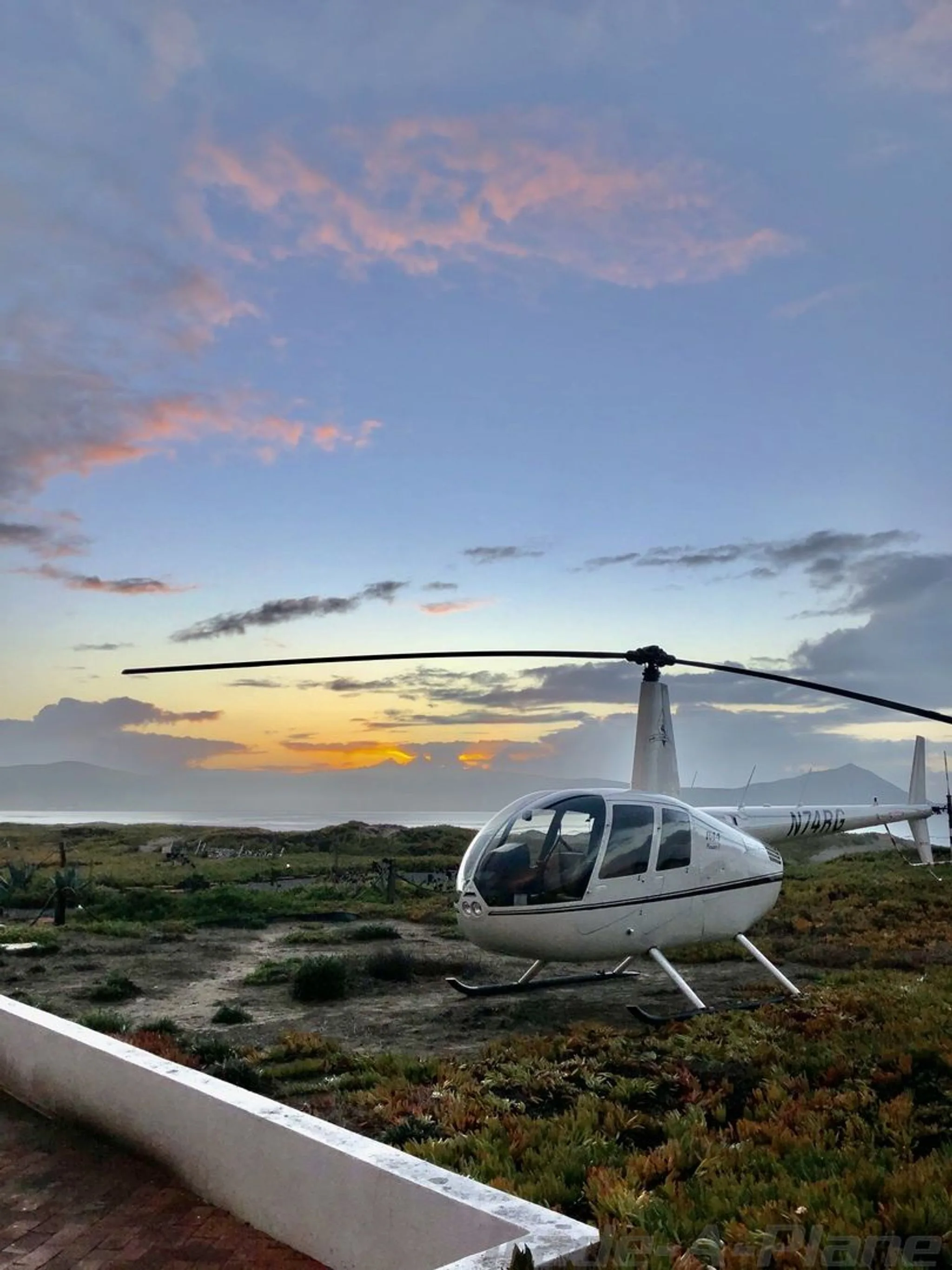


Free — save the R44 to your watchlist and track it in one place.
More Robinson R44manuals & documents
See all 13 →- Robinson R88 SpecificationsSpecifications
- Continuing Airworthiness Notice 73-006 Revision 2Maintenance Manual
- Drive belt tensioning motor failure involving Robinson R44 helicopter, VH-ZUJOther Documents
- Supplemental Type CertificateType Certificate
- SAFO 11008Service Bulletins
- Pilot’s Operating Handbook for Robinson R44Pilot's Operating Handbook
- Service Bulletin Fuel Systems Bulletin No.: PRS-109 Revision No.: 1Service Bulletins
- Flight Review GuideChecklist
- WEIGHT AND BALANCEWeight And Balance
- Service Information for RSA-10AD1 Fuel Injection ServoSystems Description
- ROTORCRAFT FLIGHT MANUAL SUPPLEMENT for the installation of the TYLER ROB-001 UNIVERSAL MOUNTS to the ROBINSON R-44 & R-44 II HELICOPTERFlight Manual
- SCHEDULE OF AIRWORTHINESS DIRECTIVESAirworthiness Directives
If you fly the Robinson R44, you may also be researching these.
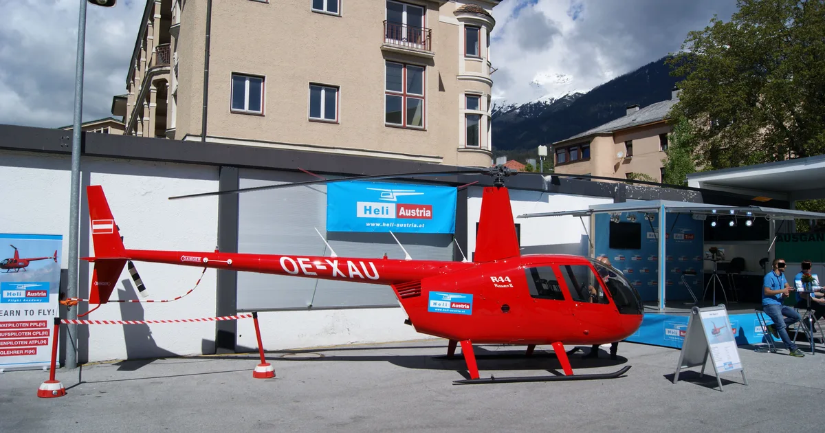
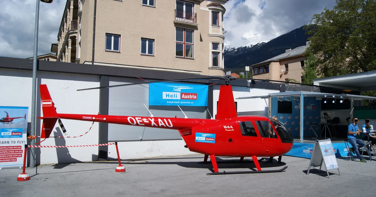
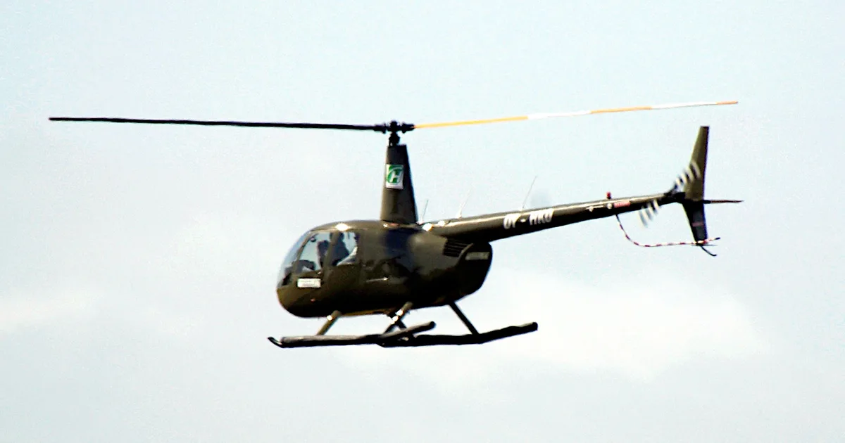

In this document
Introduction
The introduction outlines the significance of understanding helicopter performance and its impact on safety. It highlights that many accidents are performance-related, particularly during take-off and landing, and stresses the need for thorough preflight preparation and performance calculations.
Performance Factors
This section discusses various factors that can adversely affect helicopter performance, such as weight, air density, and environmental conditions. It emphasizes the importance of using accurate performance data from flight manuals and conducting power checks to validate performance capabilities.
Weight
The section explains how increased gross weight requires more lift and power for hovering and climbing. It discusses the relationship between weight and hover ceiling, urging pilots to accurately calculate the helicopter's weight before flight to ensure safe operations.
Air Density
Air density significantly affects helicopter performance, particularly engine power and rotor efficiency. This section provides formulas for calculating density altitude and explains how temperature, pressure, and humidity impact performance.
Wind Effects
The effects of wind on helicopter performance are detailed, including the advantages of headwinds for take-off and landing, and the dangers of tailwinds. The section advises pilots on how to assess wind conditions accurately to enhance safety during operations.
Safety notes
- Pilots must ensure compliance with operating limitations specified in the aircraft flight manual.
- Accurate performance calculations are essential to prevent accidents during take-off and landing.
Full document text
Helicopter performance 2 Cover photo: iStock.com/chameleonseye The technical assistance provided by North Shore Helicopters, Kāpiti Districts Aero Club, GCH Aviation, Ardmore Helicopters and Christchurch Helicopters in compiling this booklet is gratefully acknowledged. See the CAA website for civil aviation rules, advisory circulars, airworthiness directives, forms, and more safety publications. Visit aviation.govt.nz. Every effort is made to ensure the information in this booklet is accurate and up-to- date at the time of publishing, but numerous changes can occur with time, especially in regard to airspace and legislation. Readers are reminded to obtain appropriate up-to-date information. Contents Abbreviations ....................................3 Introduction ..................................... 4 Some accident examples ....................5 PIC responsibilities .............................7 How to comply .....................................7 Performance factors ......................... 8 Weight ............................................... 8 Air density .......................................... 9 Wind .................................................15 Ground effect.................................... 18 Slope ...............................................20 Surface.............................................20 Other considerations .......................21 Power checks .....................................21 Decision points ................................. 23 Speed control ...................................24 Overpitching .....................................24 Pilot technique ..................................24 Vortex ring state ............................... 25 Rotor condition ................................. 26 Contingencies ................................... 26 Know your helicopter ......................... 26 Determining performance ................ 27 Examples .......................................... 27 Conclusion ...................................... 33 Performance questions ......................34 AMSL Above mean sea level FATO Final approach and take-off hPa Hectopascals HPA Available horsepower HPR Required horsepower IGE In ground effect ISA International Standard Atmosphere MAP Manifold absolute pressure OGE Out of ground effect P alt Pressure altitude QNH An altimeter sub-scale setting to obtain elevation when on the ground TAS True airspeed TLOF Touchdown and lift-off area Safety Safety Around Helicopters How you can operate safely around helicopters – with modules on the land, in the bush, at sea, in the mountains, and more. Around Helicopters nd e t are gs e and ral wn. Land nd in a cued by odule ose and ite, with daylight g in ation e 2006. s Abbreviations Safety Around Helicopters This video, produced in 2006, is ideal for your passenger safety briefings because it is designed for everyone who works around helicopters, especially non- aviation passengers. The introduction has information for everyone, and there are separate modules on: • industry • going bush • corporate and tourism • the mountains • rescue on the land • all at sea • helicopter identification. You can order your copy from videonz.co.nz or watch online at youtube.com/@CivilAviationAuthorityNZ. We also recommend you read the Mountain flying GAP booklet in conjunction with this booklet. 3 Helicopter performance This booklet examines the factors affecting helicopter performance, and provides guidance to help pilots carry out safe operations. A significant number of New Zealand helicopter accidents are performance- related. Most of them occur during take-off or landing. The remainder are associated with external load or confined-area operations. Many of these accidents occurred when the helicopters were being operated from sites that were elevated, facing out of wind, restricted by terrain, sloping, or had rough surfaces. In most cases, the sites were on ridgetops or in confined, steep- sided valleys. Often the helicopters were being operated at high gross weights, in higher ambient temperatures, and lower air pressures than standard. The circumstances of performance-related accidents usually indicate the pilot hadn’t ensured there was sufficient power available for the intended manoeuvre in the prevailing conditions. These accidents could have been prevented, had the pilots been fully aware of the prevailing conditions, and taken the time to determine the performance capabilities of their helicopter before committing themselves. Accident prevention relies on thorough preflight preparation, of which flight manual performance chart calculations are an integral part. Because the ambient conditions at the intended point of operation can be quite different from those planned for, and because flight manual performance graphs can sometimes be optimistic, calculated values must always be validated by an actual power check at the operating site. Photo courtesy of Heliflite Charter & Training Ltd Introduction 4 Some accident examples The following examples illustrate how a series of events can lead to an accident, in which a lack of performance is a key causal factor. Although we’ve used piston engine examples here, gas turbine powered helicopters are also susceptible to performance problems. Insufficient power The purpose of this Robinson R22B helicopter flight was to land a passenger by the south side of a small lake, at 5300 feet above mean sea level (AMSL). A small tramping pack was carried on the cargo hook. The only clear approach was from the south, and a missed approach was not practicable from late final. A high reconnaissance was flown and a landing point selected on a knoll. A power check suggested that a hover landing should be possible, and the lake surface indicated no wind. On short final, the pilot found that the helicopter did not slow as intended. After losing translational lift, the rotor RPM started to decay, and the descent was not
Show full textShow less
arrested. The pilot turned the helicopter away from the knoll toward lower but uneven ground, in an effort to make a controlled landing. The ensuing heavy landing collapsed the left skid gear, and the helicopter rolled over. The pilot applied full carburettor heat after he had reduced power for the approach, but he didn’t return the control to the COLD position before landing. A subsequent flight check in the area showed that this reduced the available manifold absolute pressure (MAP) by half an inch. The hook load was not jettisoned. Analysis For the conditions at the time, the flight manual indicated that the R22B could achieve an out of ground effect (OGE) hover at 5300 feet AMSL, with the two persons and hook load on board, but it seems from events that the margins were small. The loss of MAP from having carburettor heat selected, together with a possible light tailwind, presumably tipped the balance. The situation would have deteriorated fairly rapidly, but by jettisoning the cargo hook load the pilot might have restored the balance enough to prevent the accident. Photo: CAA 5 Helicopter performance Photo: CAA Too high A tramper who wished to be flown to a hut in the mountains approached a helicopter operator, advising him that the hut was at an elevation of 1450 feet AMSL. The pilot assigned to the job flew the Robinson R22B to the airport, where the tramper waited. The pilot assessed the weight of the tramper, pack, helicopter, and fuel, and considered them to be within the capability of the helicopter to operate at the elevation of the hut. Some items from the tramper’s pack were stowed under the seat, and the pack was placed at his feet. The pilot did an IGE hover check, and found that 24 inches of MAP was required for the hover. The tramper guided the pilot to the hut, which turned out to be at a much greater height than expected. The pilot did a power check, and elected to land on a nearby tussock-covered saddle. He approached the saddle obliquely to allow for an escape route, and flew the helicopter in a shallow approach at 22 inches MAP. At about 15 feet above the landing site, the pilot noticed the RPM was at 97 percent – the bottom of the normal range – and opened the throttle fully. No more power was available, and believing a landing was inevitable, the pilot tried to control the flight path by increasing collective pitch. He could not arrest the helicopter forward motion by applying full aft cyclic, and the helicopter began to rotate, touching down heavily. The helicopter then pitched slowly onto its nose, and fell onto its right side. The tramper had misled the pilot about the correct site elevation, and used the NZMS 260 series of maps, which showed heights in metres. The altitude of the hut was 1450 metres AMSL (4750 feet), not 1450 feet, as the tramper reported. Another significant factor was the helicopter weight and balance. Using the weights the pilot estimated, the helicopter take-off weight was 635 kilograms; 13 kilograms over its maximum. This inevitably placed a premium on the power required. Moreover, by placing the pack at the tramper’s feet, the helicopter was probably loaded outside its forward C of G limits. This would have added to the difficulties of using cyclic to arrest the helicopter forward motion. Lack of a power margin was inevitable given the helicopter weight and the density altitude at the landing site, but the pilot did 6 not recognise the shortfall in power. The pilot carried out a power check estimate as he approached the landing area, but did not apply the technique fully. Had he done so, it would have shown the power required was 24 inches MAP and the power available was 23 inches. A no-go situation would then have been evident. After recognising that there was insufficient power available, the pilot used an incorrect recovery technique. At 15 feet above the landing site, the helicopter could have been accelerated to about 15 knots to gain translational lift. This would have significantly reduced the power required, and the pilot could have taken some time to figure out another way of delivering the tramper and his pack. Or, the pilot could have considered the cost and complications of a potential crash compared with the cost of turning around. He could have landed in the lower ground (in the background of the picture to the left), and reassessed the job, with the possibility of using a more appropriate aircraft. He could also have landed at the lower site to offload a portion of the cargo and/or the passenger, then flown to the higher intended site, offloaded that portion of the load, and gone back down to pick up the rest of the load. Analysis Overall, this flight had the odds stacked against it being successfully carried out, although there were numerous opportunities for the pilot to have rectified the situation along the way. PIC responsibilities Section 14 of the Civil Aviation Act 2023 says that the pilot- in-command is responsible for the safe operation of their aircraft and for the safety of their passengers, crew, and cargo. More specifically, rule 91.201(2) states that “A pilot-in-command of an aircraft must … during the flight, ensure the safe operation of the aircraft and the safety of its occupants…”. Rule 91.109 states, “A person must not operate an aircraft unless it is operated in compliance with the operating limitations specified in the aircraft flight manual.” How to comply You can comply with rule 91.109 by using the performance data graphs in the helicopter flight manual. Enter the graph, and trace the applicable data to determine the performance capabilities for the given conditions. Then, confirm those values with a power check. Most flight manuals have graphs for determining density altitude, IGE and OGE hover ceilings, take-off distances, and rate-of-climb performance. Between helicopter types, there is considerable variation in the standard of information presented in these graphs. The use of these graphs is discussed, with worked examples, later in this booklet. 7 Helicopter performance Photo courtesy of Amalgamated Helicopters (NZ) Ltd Performance factors In this section, we discuss how various physical and environmental factors can adversely affect helicopter performance. We’ve tried to avoid using rule-of-thumb methods for determining performance, because there are differences between helicopter types. The application of rules- of-thumb could be misleading. Instead, we’ve given several performance examples, from a range of helicopter types, to illustrate how each performance factor affects performance capability. Refer to your helicopter flight manual or operating procedures, or ask your chief pilot or instructor for the specific performance information that applies to your helicopter. The performance values derived from the following examples may be significantly better than what the helicopter can actually achieve. They’re based on a brand new helicopter (that’s to say, with an ‘on spec’ engine, clean rotor blades, and correct rigging), being flown by an experienced test pilot. Engine performance may deteriorate between overhaul periods. All examples have been derived from flight manual performance graphs only, and they would normally be validated by an actual power check, under the ambient conditions existing at the point of intended operation. Some flight manuals contain performance charts that have minor variations (for example, generator ON, sand filter fitted, bleed air ON). You must use the correct variant so that accurate performance data is obtained. Weight The greater the gross weight of the helicopter, the greater the lift (rotor thrust) required for hovering or climbing. The available lift is proportional to the collective setting and the associated rotor blade angle of attack. The power available determines the maximum collective pitch setting that can be maintained at the optimum rotor RPM. The heavier the helicopter, the greater the power required to hover (and for flight in general), and the smaller the margin between the power required and the power available. The higher the gross weight, the lower the hover ceiling, and therefore the more restricted the helicopter will be in where it can operate. This can be seen from the following two examples. 8 Effect of increasing weight on IGE hover ceiling example: Schweizer 269C Gross weight 725kg 910kg Temperature +27°C at sea level +27°C at sea level QNH 1003 hPa 1003 hPa Hover ceiling 11,350 feet P alt (1013 hPa set) 5400 feet P alt (1013 hPa set) Which gives 11,050 feet indicated alt (QNH set) 5100 feet indicated alt (QNH set) Pilots must ensure that they always use an established method to accurately determine the gross weight of the helicopter before flight. This means totalling the weights of the crew, passengers, fuel, and any other items being carried, in a systematic way, which will allow accurate performance calculations to be carried out. A check of the power required to hover IGE can then be made, to confirm that the actual weight of the helicopter corresponds to this figure. Many flight manuals have graphs to help determine this. Air density As air density decreases, both engine (particularly normally aspirated piston engines) and aerodynamic performance (rotor thrust) decrease. Effect of pressure on density Atmospheric pressure decreases with increasing altitude, because the air near the earth’s surface is compressed by the air above it. The reduced pressure allows the air to expand and to become less dense as a result. Effect of temperature on density Temperature generally decreases with altitude. This makes the air contract, and become more dense. However, the pressure reduction of increasing altitude has the greater effect, over the increase in density from the reduction in air temperature. Effect of humidity on density There is an accepted method to determine density altitude, which should be used in warmer areas of New Zealand. You can calculate density altitude using the following formula: Density Altitude in Feet = Pressure Altitude in Feet + (120 x (OAT°C – ISA Temperature °C)) Below is a shortened version of the formula, where: DA = Density Altitude (ft) PA = Pressure Altitude (ft) OAT = Outside Air Temperature (Celsius) ISA = Standard Temperature (Celsius) DA = PA + (120 x (OAT – ISA)) For example, if the temperature at 3000ft pressure altitude is 12°C, the density altitude formula will be: DA = 3000 + (120 x (12 – 9)) Note: 9 is the ISA temp (°C) for 3000ft. Therefore, the density altitude will be 3360ft. Pilots must develop a keen sense of moisture assessment, and adjust their expectations of the helicopter’s performance accordingly. Hot and humid conditions usually bring about reduced engine (and aerodynamic) performance and reduced lift. These factors should never be underestimated when operating at high density altitudes and gross weights. 9 Helicopter performance Sea level Stratus and nimbus clouds High cumulus clouds Mt Cook Mt Everest Cirrus clouds 40 25 20 15 10 5 0 35 30 -56 -34 -25 -15 -5 +5 +15 -54 -44 377 466 572 697 843 1013 188 239 301 0.449 0.533 0.629 0.739 0.862 1.000 0.247 0.311 0.375 Height above sea level (thousands of feet) Temp (°C) Pressure (hPa) Relative density Figure 1 International Standard Atmosphere International Standard Atmosphere An International Standard Atmosphere (ISA) has been established to enable comparison of aircraft performance, calibration of altimeters, and other practical uses. In the ISA, a particular pressure and temperature distribution with height is assumed. At sea level the pressure is assumed to be 1013.2 hPa, and the temperature 15°C. ISA also assumes dry air. Pressure altitude In ISA, any pressure level has a standard corresponding altitude called the pressure altitude, based on a lapse rate of approximately one hPa per 30 feet at lower levels. Pressure altitude is the height that will register on a sensitive altimeter whenever its subscale is set to 1013.2 hPa. At any ISA pressure level, there’s also a corresponding temperature called the ISA temperature. In ISA, temperature falls off with height at a rate of 1.98°C per 1000 feet up to 36,090 feet, above which it is assumed to be constant (see Figure 1). Warm air is less dense than cold air. So, when the temperature at a given altitude is higher than the standard atmospheric temperature, the air at that altitude will be less dense. Density altitude Density altitude represents the combined effect of pressure altitude and temperature. Density altitude is defined as the height in the standard atmosphere, that has a density corresponding to the density at the particular location (on the ground or in the air), at which the density altitude is being measured. Calculate density altitude by taking pressure altitude and adding (or subtracting) 120 feet for each 1°C above (or below) ISA. This isn’t something that pilots normally have to do in practice, 10 Figure 2 Effect of increasing altitude on HPA / HPR (available horsepower/required horsepower) Effect of increasing altitude on HPA / HPR Max power available at sea level Excess power available A B Power Max straight and level speed TAS (true airspeed) A = Power required OGE hover B = Power required IGE hover Power available at increased altitude Power required at sea level Power required at increased altitude because the temperature reference lines on a performance graph works this out for them. However, pilots still need to understand how this is calculated, so see the “Determining performance” section on pages 27-32 for details. Helicopter performance is highly dependent on air density, which directly affects engine power, drag, and rotor efficiency. As air density decreases, performance decreases. Density altitude provides a basis for relating air density to ISA, so that comparative helicopter performance can be readily determined. High density altitudes are usually found at high-elevation take-off and landing sites, particularly when the air temperature is high, and the atmospheric pressure is low. Such conditions are commonly found in the Southern Alps or the Central North Island. Operating from such high-density altitude sites can be perilous, so your performance calculations must be consistently accurate. The effect of a high-density altitude on the power developed from a normally aspirated piston engine is particularly adverse, meaning that less power will be available for hovering, taking off, and landing. The power available from a gas turbine engine also falls off at a similar rate as density altitude increases. The engine may ultimately become temperature or gas producer speed limited, which will reduce its available power. The margin between available power, and the power required to hover at high gross weights and high-density altitudes, is often small for helicopters. Density altitude becomes a lot more important to the helicopter pilot than to the fixed-wing pilot (see Figure 2). In practical terms, an increase in density altitude has several effects on helicopter performance: • reduced hover ceiling – means the choice of take-off and landing sites available becomes limited • reduced operating margins – means reduced payloads • reduced rate-of-climb performance – means obstacle clearance can be adversely affected. Trans-shipping of passengers or load may be necessary. 11 Helicopter performance You should gain as much prior knowledge as practicable of the ambient conditions at the landing site. Take-off For any given weight, the higher the density altitude at the departure point, the more the power required to hover, because of reduced rotor efficiency. With engine performance already reduced, the amount of excess power available to hover can be small. Under certain conditions, a helicopter may not have sufficient power available to take off and satisfactorily clear obstacles. Limited-power techniques, such as a cushion-creep or a running take-off, may need to be made. These aren’t usually options in a confined-area operation, because there may be insufficient distance available, or the surface may be unsuitable. For this reason, you should always carefully assess the power needed to achieve the type of take-off you’re planning. For power checks, see page 21. Translational lift must be achieved as soon as possible after lift-off, and the helicopter accelerated to the speed for best climb angle. If not specified in the flight manual, this is approximately translational lift speed plus 20 knots. Photo courtesy of Christchurch Helicopters 12 Landing Given that a normal landing is preceded by a hover, the limited power available at high-density altitudes can be just as much of a problem when landing. If the landing site has a high-density altitude, you might not have enough power to hover at your operating weight. In such conditions, you can land safely by doing a run-on or a zero-speed landing, but this isn’t always an option in a confined space or on a rough surface. Gain as much prior knowledge as practicable of the ambient conditions at the landing site. If relevant, allow for surface heating, which can cause the air temperature immediately above the landing site to be higher than the theoretical value, based on the temperature of the day and the lapse rate. Before attempting the flight, calculate the hover ceiling using flight manual performance graphs. This will give you some idea of what to expect. Note that the performance graphs don’t consider adverse factors, such as rotor condition and ground surface type. Near the landing site, and before a landing is attempted, confirm the predicted hover ceiling with a power check. Near the landing site, and before a landing is attempted, confirm the predicted hover ceiling with a power check. Photo courtesy of Christchurch Helicopters 13 Helicopter performance Effect of increasing temperature on OGE hover ceiling example: R22B at 590kg gross weight Temperature –10°C +10°C QNH 1005 hPa 1005 hPa Hover ceiling 7100 feet P alt (1013 set) 5900 feet P alt (1013 set) Which gives 6860 feet indicated alt (QNH set) 5660 feet indicated alt (QNH set) Effect of reducing atmospheric pressure on OGE hover ceiling example: R22B at 590kg gross weight Temperature +10°C +10°C QNH 1030 hPa 995 hPa Hover ceiling 5900 feet P alt (1013 set) 5900 feet P alt (1013 set) Which gives 6410 feet indicated alt (QNH set) 5360 feet indicated alt (QNH set) Effect of increasing temperature on OGE hover ceiling example: AS350B2 at 2180kg gross weight Temperature –10°C +10°C QNH 1005 hPa 1005 hPa Hover ceiling 9400 feet P alt (1013 set) 7400 feet P alt (1013 set) Which gives 9160 feet indicated alt (QNH set) 7160 feet indicated alt (QNH set) Effect of reducing atmospheric pressure on OGE hover ceiling example: AS350B2 at 2180kg gross weight Temperature +10°C +10°C QNH 1030 hPa 995 hPa Hover ceiling 7400 feet P alt (1013 set) 7400 feet P alt (1013 set) Which gives 7910 feet indicated alt (QNH set) 6860 feet indicated alt (QNH set) Some examples The following examples illustrate the relative effects that changing temperature and pressure individually can have on helicopter performance. Remember that, when operating at high density altitudes and weights, the ‘four Hs’ (High, Hot, Heavy, and Humid) all combine to reduce helicopter performance. 14 Wind Headwind Headwind is a big advantage, particularly if it is associated with upflow. This effect, however, reduces at wind speeds above the minimum power speed. Headwind is a big advantage, because it can mean considerably improved take-off and landing performance. It can be particularly useful when the helicopter is being operated at the limit of its lifting capability, for example, sling load operations. Ideally, the helicopter should be orientated so the wind is always from its front quarter. Knowing which direction the wind is coming from is very important, especially in light wind conditions. Some helicopter flight manual performance graphs (for example, Bell 206B3) have a critical wind azimuth area, in which adequate control of the helicopter is not assured when the wind is from anywhere within the specified azimuth area. As a result, hover ceiling will be reduced. Taking off into wind means a lower groundspeed on lift-off, which makes it easier to bring the helicopter to a hover, if you need to reject the take-off. Climbing into wind also gives the steepest angle of climb after take-off, which is good for obstacle clearance. Landing into wind results in a lower groundspeed, which leaves more time to judge the approach. The increase in air flow through the rotor disc means that less power is required to carry out the approach, leaving more power available for the unexpected. A headwind also allows the helicopter to remain in translational lift for longer during the landing approach, meaning a smoother transition and a smaller power increase in the final stages of the approach. Avoid downwind approaches where possible, because they can result in a vortex ring state, sometimes referred to as power settling. A difficulty you could face, when planning to land at a site where the terrain is significantly affecting the wind speed and direction, is accurately assessing the headwind component. Photo courtesy of Heliflite Charter & Training Ltd Headwind can be particularly useful when the helicopter is being operated at the limit of its lifting capability, such as in sling-load operations. 15 Helicopter performance ‘Power-pedal-plan’ Coming into confined areas, make sure you have power in place, pedal in the correct position, with a controlled rate of descent. In the event of an aborted landing and having to fly away, you only need very minimal control input. Consider that, when descending below a treeline to land, the assisted wind and increase in temperature below the treeline will degrade aircraft performance. Make your decision early to fly away and reassess. If you don’t identify these factors, you’ll run out of two things at exactly the same time: horsepower and ideas. This is particularly so when the landing site is in a valley. Wind speed and direction may be reasonably constant on the tops, but can be far less predictable down in the valley. The danger is starting an approach based on a particular headwind component, only to have it abate or change direction as the helicopter descends into the valley. Translational lift may be lost, and the power required may increase to a point beyond the power available, resulting in an increased rate of descent and an undershoot. Having a headwind component during the final stages of an approach in this kind of situation shouldn’t be taken for granted. Tailwind Lifting off with a tailwind means a higher groundspeed and a decreased angle-of- climb, which is bad for obstacle clearance. Avoid tailwind take-offs unless absolutely necessary. They should only be attempted by experienced pilots. An important factor, and one that’s often overlooked by pilots, is the detection of a tailwind while on approach to land. If the wind speed and direction at the landing site isn’t obvious, an estimate of whether the groundspeed matches the indicated approach airspeed is good practice. Photo: CAA 16 Most helicopters will give an indication when decelerating through translational lift, by the presence of aerodynamic shuddering. Additionally, the observation of higher-than-expected power required for the stage of the approach, is another clue that a tailwind is present. Remember – in light wind conditions, accurate wind direction assessment can be difficult. Only a few knots of wind on the tail can make a big difference to the power required to satisfactorily control the rate of descent during an approach, especially when landing at high altitudes. Landing with a tailwind often results in an early increase in the power required, which may mean that the power available is exceeded. This normally results in an unwelcome rate of descent and an undershoot. Helicopters can be directionally unstable in a tailwind, and require anti-torque pedal inputs to maintain the desired direction of travel, which will increase the power required. There’s also the possibility of entering a vortex ring state, or power settling. Rates of descent should be kept less than 300 feet per minute during the final stages of the approach (that’s to say, for airspeeds below about 30 knots) to minimise the chances of power settling occurring. If a significant tailwind is detected on approach, an early decision to go around is usually the best course of action. Tailwind take-offs and landings should be avoided wherever possible, unless there’s a very large margin of power available, and the pilot is experienced. Maintaining a good awareness of the wind velocity, power available, airspeed, and rate of descent is always important during these phases of flight – whatever the wind direction. Crosswind A crosswind situation will affect take-off and landing performance, because of the reduced headwind component and the difficulties in maintaining directional control. For example, if the wind is 30 degrees from the take-off or landing heading, the headwind is reduced by 14 percent. If the wind is 45 degrees off, the headwind is reduced by 31 percent. A light crosswind may be either an advantage or disadvantage with respect to take-off and landing performance, depending on whether the wind is from the right or left quarter. If the helicopter main rotor rotates in an anti-clockwise direction, when viewed from above (American designs), a crosswind from the left side will assist performance. This happens because the wind effect reduces the thrust required from the tail rotor to counter main rotor torque. The reduced power needed then makes more power available to the main rotor for increased lift. Exercise caution if using this technique, as the main rotor vortices in low speed flight will interfere with tail rotor efficiency, potentially leading to an LTE (loss of tail rotor effectiveness) event. If the wind is from the right quarter, it will push against the tail boom, vertical stabiliser, and the tail rotor disc in the same direction as main rotor torque. This increase in the total rotational force must be overcome by additional tail rotor thrust, absorbing more power from the engine. If the engine is unable to produce the additional power needed to do this, you must reduce collective pitch, causing the helicopter to descend. You must do this to conserve rotor RPM, otherwise the helicopter will rotate and descend uncontrollably. 17 Helicopter performance Turbulence and wind shear The possibility of turbulence and wind shear should be considered when determining take-off and landing performance. Wind shear is a change in wind speed and/ or direction over a very short distance. The presence of wind shear can cause the sudden loss of translational lift, and increase the power required to that of OGE hover and beyond. This is particularly the case if accompanied by a downdraught. Local terrain, trees and buildings all influence the flow of the wind near them. The mechanical turbulence resulting from this disturbed airflow may become marked in the lee of the obstruction. In winds below 15 knots, the turbulence in the lee of an obstruction may extend vertically to about one third higher again than the height of the obstruction. In winds above 20 knots, eddies can occur on the leeward side to a distance of about 10 to 15 times the obstruction height, and up to twice the obstruction height above the ground. A gusty wind situation, where wind shear is likely to be present during take-off, will require a greater power margin to deal with any unexpected loss of airspeed and accompanying sink. Gusty conditions when landing can result in varying power demands and an unstable approach. This may mean you have a problem maintaining a stable RPM range, and that the engine is unable to be accelerated (especially a gas turbine) to meet the demand for power. Large anti- torque pedal inputs to maintain directional control also act to reduce the excess power available. Ground effect Hover in ground effect When hovering at approximately a 3-feet skid height, the velocity of the downwash from the blades reduces, because the airflow has to change direction by 90 degrees on contact with the ground. This change in velocity is felt at the rotor disc, in a similar way that the oncoming relative airflow to an aerofoil feels the downwash behind it (that’s to say, induced drag). The result of this interference is to reduce the induced flow through the rotor disc. If the blade angle and RPM are kept the same, the blade angle of attack will increase as the induced flow decreases. This means that lift production increases, and you must lower the collective lever to reduce the blade angle of attack and prevent the helicopter from gaining height. Since lowering the collective means reducing the power required to maintain the same rotor RPM, less power is required to hover IGE. Photo courtesy of John Newsham and Heliflite 18 Most helicopter flight manuals provide performance graphs to calculate IGE hover ceiling at a skid height of between 2 to 5 feet. Remember, an IGE hover is based on hovering over a flat and relatively smooth surface. Hover out of ground effect When hovering above a 3-feet skid height (OGE), the ground resistance is reduced or even eliminated, so there’s an increase in the induced flow when compared with an IGE hover. If the blade angle and RPM are kept the same, the angle of attack will decrease as the induced flow increases. This means that lift production reduces, and you must raise the collective lever to increase the blade angle of attack to prevent the helicopter from descending. Since raising the collective means increasing the power required to maintain the same rotor RPM, more power is required to hover OGE. This means that OGE hover ceiling will be considerably lower than IGE hover ceiling, as low as 60 percent of IGE. Practical considerations When using hover-ceiling charts to determine performance capabilities under a given (known) set of conditions, you should use conservative values until you’re familiar with the operation. Performance calculations should be based only on an IGE hover (that’s to say, a lesser performance margin) when the following criteria are well known: • familiarity with, and currency on, type • accurate assessment of helicopter weight • familiarity with the landing zone being used, especially approach and departure routes, obstacles, escape routes, surface, and landing aids • ambient conditions at the landing zone, especially wind direction and density altitude. If all the above criteria are not able to be quantified (or a sling load delivery is involved), then the operation must be based on OGE hover performance. Caution: There will be situations where further calculations may be needed to depart safely from some pads that, for instance, require a towering climb from a confined area. Uneven terrain offers only partial benefits of ground effect. Photo courtesy of Amalgamated Helicopters (NZ) Ltd 19 Helicopter performance Slope Hovering above sloping ground needs more power than that needed to hover over a flat surface. Hovering over a slope allows some of the downwash on the downhill side to escape. This means the induced flow through the rotor disc is not as greatly affected, resulting in a loss of the benefits that would permit an IGE hover. In this situation, you should base your performance calculations on an OGE hover. An upslope wind, when hovering above a slope, has the advantage of requiring less into-slope cyclic to hold the helicopter level. This means more cyclic movement is available to control the helicopter. Strong upslope winds can reduce tail rotor authority and, if anti-torque pedal inputs are made, increase the power required. Surface Any surface that absorbs the downwash from the rotor blades will reduce the benefits of ground effect. Hovering over long grass, rough water, rocky riverbeds, a tree canopy, or similar surfaces, requires more power and will reduce the IGE hover ceiling. Hovering above sloping ground needs more power than that needed to hover over a flat surface. Photo courtesy of Amalgamated Helicopters (NZ) Ltd 20 Other considerations Power checks Conditions at take-off and landing sites are likely to differ from what has been allowed for during flight manual performance calculations. To take this into account (plus the fact that flight manual performance graphs tend to be optimistic), and to confirm the amount of excess power available, you must make an operational assessment by doing a power check before committing to a take-off or landing. Before take-off Determining the excess power available at take-off gives a good idea of whether obstacle clearance will be adequate. It also gives an idea of what the climb performance is likely to be, and whether landing at an even higher elevation will be feasible. Checking the excess power available prior to take-off is a useful tool to indicate a departure from ‘expected’ performance values. See the section on power assurance checks on page 23. The excess power in hand for take-off can be determined as follows. • Hover IGE, and note the minimum power required to do so. • Check the maximum power available for the given ambient conditions by slowly* starting a vertical take-off until maximum collective input is achieved. Note the corresponding MAP or torque. Sometimes you may already have a good idea of this value from a power check prior to landing at the site. * Taking off slowly prevents the possibility of entering a vortex ring state, if less power than expected is available and the helicopter sinks unexpectedly. • Allow for a reduction in the power required to hover if there’s a significant headwind, otherwise the value obtained may be misleading. • Compare the two values. The difference represents the power margin available and indicates the type of take-off that will be possible (that’s to say, running, cushion-creep, towering, or vertical). • The prevailing wind, terrain, and escape routes at the site will then dictate what type of take-off profile needs to be made. Before take-off, assess power available. Photo courtesy of Amalgamated Helicopters (NZ) Ltd 21 Helicopter performance If the power available for take-off is marginal, you should use the cushion-creep method. This means you should: • turn the helicopter into wind • hold the maximum allowable rotor RPM • raise the collective lever until the skids clear the surface, then use a small amount of forward cyclic to initiate forward momentum • keep the skids as close as practical to the ground to fully utilise ground effect until translational lift is achieved • accelerate to best-rate-of-climb speed and establish a satisfactory climb. The main objectives of this technique are to keep the total rotor thrust almost vertical, and to utilise ground effect as much as possible. If more power is needed, a reduction in rotor RPM will occur. You may be tempted to increase the collective pitch to avoid the helicopter settling back on to the ground. Increasing rotor blade angle of attack, however, increases drag, further reducing rotor RPM. With any decrease in rotor RPM, there will be a reduction in the effective disc area, because of an increase in the coning angle. This extreme situation may not be recoverable, and is referred to as overpitching. In the event a pilot overpitches the rotors, only one recovery method is available. That’s to reduce the blade pitch angle, by lowering the collective with the throttle set at maximum. Overpitching is discussed on page 24. Refer to your helicopter flight manual, or consult an instructor or senior pilot for specific details on doing a power check prior to take-off. Before landing Many landings are preceded by a hover, and since power required to hover is greater than that required for forward flight, special care is needed for landings at high gross weights in high density altitudes. Keeping the wind on the nose is essential. Photo courtesy of Christchurch Helicopters 22 The method for assessing the power in hand before landing is based on similar principles to that used for the take-off, except that it’s normally done in forward flight, and at an altitude similar to the landing site. A power check is usually accomplished as follows. • Fly straight and level at a pre- determined speed (usually minimum- power speed) with landing rotor RPM selected, taking care to avoid air that is subject to up or downdraughts. • Note the MAP or torque. • While maintaining the same rotor RPM, briefly apply full power and note the corresponding change in MAP or torque. Note, most aircraft can be checked in this way, but refer to the manufacturer’s aircraft flight manual to be sure. If you’re using this method, it’s not usually practical or necessary to maintain the same airspeed at this point. • The difference between the two values gives a clear indication of the type of approach and landing that can be safely carried out at the site. Any headwind component will be an advantage, but you shouldn’t rely on it, as it may abate just when you need it most. Head wind assessment at the power check stage for landing may disappear when landing in a sheltered landing site, such as amongst trees or on the lee side of a ridge. Using the R22 as an example, six inches of excess MAP should enable an approach to be made to an OGE hover. However, just three inches of excess MAP will usually mean that only a run-on landing will be possible – but this isn’t recommended. Refer to the flight manual for specifics. An alternative method is to check the power required to hover OGE adjacent to the landing site, and compare it with the power available. This must be done with a predetermined escape route in mind, over a clear area with plenty of height to spare, because the power required to hover OGE at high density altitudes can be large. The helicopter can quickly develop a high rate of descent if there’s insufficient power available, so be alert and avoid entering a vortex ring state. Power assurance checks Because engine performance can deteriorate between overhauls, you should do regular assurance checks to confirm that engine output is within the manufacturer’s specifications. ‘Below spec’ engines can’t be relied on to meet flight manual performance graph figures. Ensuring that engine instruments are accurately calibrated is also an important part of the power assurance process. Incorrect readings are dangerous, and can mislead a pilot into thinking there’s more power available than there really is. You should record the results of a power assurance check, and establish a baseline for the engine concerned. Subsequent power checks will then indicate any degradation in engine performance, and can be considered. Decision points A decision point should always be nominated where the take-off will be rejected, the load jettisoned, or the landing approach discontinued, if things aren’t going as expected. For take-off, this is the point at which either there’s sufficient distance and height remaining to safely bring the helicopter to a hover; or to accelerate it to a safe flying speed down a pre-determined escape route, if the helicopter climbs more slowly than expected, or suffers a power loss. 23 Helicopter performance This is particularly important for multi- engine helicopters. Plan to clear obstacles in the climb-out path by at least 50 feet. For an external load operation, have a pre-determined point where the load will be jettisoned, if the helicopter doesn’t achieve adequate climb performance after lift-off. Also, have a good idea of where to put the load if the helicopter develops a higher-than-expected rate of descent (sink) on approach to land. Things can happen quickly, so the less time spent thinking about where to put the load, the better. A pre-determined plan can make all the difference. For landing, the decision point should be the height where there’s sufficient room to safely discontinue the approach while there is translational lift, if you’re not satisfied with the approach and confident that the helicopter can be brought safely to a hover. As for take-offs from challenging ridgetop sites, where possible, you should have a suitable down-slope escape route in mind before committing to the landing. Speed control Accurate speed control after take-off is important when, for obstacle clearance, you need to achieve the best angle-of-climb performance from your helicopter. For landing, accurate speed control is important so that a stabilised approach can be flown. This is particularly important when the transition from translational lift to ground effect is made – especially when making a zero-speed landing. If you get too slow, too early, the helicopter may develop a high rate of descent. Get too fast, and large or rapid control inputs may be required to overcome the helicopter inertia, where ‘power settling’* may occur. * Not to be confused with ‘settling with power’ (vortex ring). Overpitching Overpitching is a dangerous situation. The engine can no longer provide enough power to overcome the drag of the main rotor at high collective pitch settings. The result is a reduction in rotor RPM, thrust, and centrifugal force, which in turn reduces the effective lifting area of the rotor disc. You must react quickly to correct the situation and prevent a dangerous rate of descent from developing. Remember, if you’re close to the ground, there may be insufficient height to recover. Discuss techniques to recover from an overpitched state with an instructor or senior pilot. If the rotors are inadvertently overpitched, it usually means you haven’t determined whether the proposed operation was within the helicopter performance envelope. You may also not have done an adequate power check at the operating site prior to committing. Remember, gross mishandling can also bring about overpitching, even if adequate power is available. Overpitching can be prevented if you plan ahead, do the necessary performance graph calculations, and validate them with a power check at the operating site. Pilot technique Getting the best performance out of your helicopter relies on using the correct flight manual techniques, and being current enough to apply them accurately. For instance, you must ensure that the recommended maximum performance take-off technique is always used when operating out of a confined area. This includes flying the climb-out at best-angle- of-climb speed, for optimum obstacle clearance. 24 Likewise, knowing what kind of landing technique to use in a particular situation, and being able to fly it accurately, is just as important. Consult the flight manual, or an instructor, if you’re unsure what take-off or landing technique to use, where performance is a consideration. Get some dual revision if you’re rusty or not current. Vortex ring state Vortex ring state is a serious hazard all helicopter pilots need to be aware of. Vortex ring state occurs when a recirculation vortex envelops a helicopter’s rotor system, causing significant loss of lift. This can occur when the helicopter is descending at a reduced airspeed, and is most at risk of happening during downwind approaches. The likelihood of vortex ring state is increased with a helicopter at a heavier weight, due to a higher power setting requirement. The condition can be sudden, and it results in a rapid increase in rate of descent. Any increase in rotor thrust to reduce this further energises the vortices and increases the rate of descent. The standard vortex ring state recovery technique requires pilots to reduce power, by lowering the collective and accelerating forward away from the downwash. However, in the low-level environment, this may not always be possible as it consumes valuable height. Alternatively, the Vuichard Recovery technique can be used to move out of the vortex ring. This involves increasing collective to climb power, applying the appropriate pedal (generally left in American helicopters, and right in European helicopters) to keep the nose straight, and applying the appropriate cyclic (opposite to the pedal used). Of course, avoiding vortex ring state is the best course of action. You should: • remain alert to the conditions that can lead to vortex ring state • closely monitor the airspeed and rate of descent during the final approach • initiate recovery action at the first indication that you may be approaching vortex ring state. Vortex ring state. 25 Helicopter performance Rotor condition Deposits on the main or tail rotor blades, such as a frost coating, can disrupt the laminar airflow and significantly reduce the lift production. Other such deposits could include spray residue, insects, dust, dirt, and pollen. Nicks and dents, or ripped and rough leading edge blade tape, can also disrupt the laminar airflow. Keep all rotor surfaces damage-free and clean to ensure maximum performance. Contingencies Even after having worked out your helicopter take-off, landing or lifting performance, add a contingency to allow for other factors that you may have overlooked. For instance, the engine may not be performing as well as it used to; the rotors may be less efficient than they used to be; you might encounter an unexpected lull or shift in the wind; the air temperature at the landing site might be higher than anticipated because of surface heating; you might not be as current as you think you are; and so on. Remember, many flight manual performance graphs are somewhat optimistic and are based on test data from a brand-new helicopter being flown by an experienced test pilot. This is even more reason to add a contingency. When the performance figures are looking tight, always factor a contingency of at least 10 percent into your calculations. Know your helicopter It’s important that you’re thoroughly familiar with your helicopter’s performance capabilities. Spend time reading the performance section of the flight manual, and talk to other pilots who fly the same type of helicopter. Take a conservative approach to operations until you feel really comfortable with your helicopter. Photo courtesy of Christchurch Helicopters 26 Determining performance The following section contains worked performance examples, plus further examples for you to test yourself on. Examples Take-off performance example Let’s work through a take-off performance Example, using the H269C IGE hover ceiling chart provided in Figure 3 on page 29. The red line relates to the data supplied below, and the blue line provides a comparison for ‘standard’ conditions. You are the pilot of a H269C who needs to calculate the IGE hover ceiling of your helicopter, to determine if you can safely pick up some deer shooters from an elevated ridgetop site under the following conditions. You have just called them to find out what their combined weights (which includes gear) are. Can you safely accept the job? Photo courtesy of Christchurch Helicopters 27 Helicopter performance Gross weight 930kg (assume full fuel tanks) Temperature +25°C at sea level QNH 1003 hPa Wind Nil Take-off site elevation 5300 feet AMSL (there are no obstacles of note on the climb-out) Surface flat short grass Workings Step 1 The first thing we need to do is to calculate the site pressure altitude. To do this, we need to take the elevation of the landing site and correct it for atmospheric pressure. Knowing that 1013.2 hPa is ISA pressure at sea level, we calculate the difference from today’s QNH (sea level pressure), which is 1003 hPa. The difference is 10 hPa, and as each hectopascal equals approximately 30 feet, this equates to 300 feet. We must now apply this correcting figure to our take-off site elevation of 5300 feet. Do we add it or subtract it? Because the pressure is lower than standard (pressure decreases with altitude, 1003 hPa being found at 300 feet AMSL on a standard day) we add the figure to take-off site elevation, arriving at a pressure altitude of 5600 feet. Step 2 Now that we’ve determined the pressure altitude, we must calculate what is effectively the density altitude (not actually represented as a numerical value on the graph). Our sea level temperature in this case is 25°C, that’s to say, 10 degrees higher than ISA’s 15°C at sea level, and so we describe the conditions as ISA+10°C. Note: For an approximation of the theoretical temperature at a pressure altitude of 5600 feet, extrapolate the sea level temperature at 2°C cooler per 1000 feet. So, 2 times 5.6 equals 11°C colder than the 25°C sea level temperature, giving a theoretical 14°C at 5600 feet. Surface heating may, however, cause the air temperature immediately above the landing site to be higher than any derived or calculated value, which would mean an increase in the local density altitude. You may wish to make an allowance for this when entering the temperature. Carefully draw a line that represents the ISA+10°C temperature profile parallel to the existing ISA reference line, and use that as your reference datum, being careful not to confuse °F with °C. Note, some manufacturers don’t provide this ISA line, so you’ll have to draw your own, by plotting several points using the known ISA pressure altitude and temperature relationship. 28 GROSS WEIGHT ~ KG 2000 4000 6000 8000 10,000 12,000 14,000 16,000 PRESSURE ALTITUDE ~ FT 1500 700 750 800 850 900 950 0 1600 1700 1800 1900 2000 2100 GROSS WEIGHT ~ LB Reduced hover ceiling as follows if equipped with: 269A8801-5 exhaust muffler, or 269A8257-3 exhaust pipe installation, or 269A8263-1, -7, -13 or -15 exhaust Diffuser installation: 218ft. Abrasion tape on blades: 500ft. This chart is based on: • take-off power • no muffler • no exhaust pipe instl. • no abrasion tape. Key Maximum permissible weight to hover IGE at pressure altitude 5600ft in ISA +10°C Maximum permissible weight to hover IGE at 5300ft elevation in ISA condition Ambient temperature 0°F (-18°C) ISA ISA + 36°F (20°C) ISA 10°C) 40 (4) 60 (16) 80 (27) 100 (38) NOT FOR OPERATIONAL USE Figure 3 SCHWEIZER 269C helicopter IGE hover (3200 RPM) ceiling graph (take-off performance example) 29 Helicopter performance Note: If we had a reading of what the actual air temperature was at the take- off site, we would draw a line parallel to the appropriate ambient temperature line rather than the ISA line. We can now enter the vertical axis of the graph at 5600 feet pressure altitude, and track horizontally across to the ISA+10°C temperature line that we’ve just drawn. The intersection of these lines indicates the density altitude at the site. Step 3 Finally, the graph is exited by tracking vertically upwards to the horizontal axis, to determine what the maximum weight is for that density altitude. In this case, the theoretical gross weight that your helicopter could hover IGE at such a density altitude is 910kg. Since you calculated that the shooters’ combined weight, plus full fuel, would bring the helicopter gross weight up to 930kg, you would be 20kg overweight. At the lighter weight of 910kg you should, in theory, be able to hover IGE at the take- off site under these conditions, but you would have little excess power available to take off. However, if you offloaded some fuel (assuming no adverse effect on safe endurance), or made two trips, you would be considerably lighter. You could reasonably conclude that you could take off safely at this new weight, but this would need to be validated with a power check prior to taking off at the site. This would tell you what kind of take-off you could achieve, and what sort of climb performance to expect – important when operating in mountainous terrain. Landing performance example Now, work through the following landing performance example, using the Bell 206B3 OGE hover ceiling chart provided in Figure 4. Again, the red line relates to the data supplied below and the blue line provides a comparison for ‘standard’ conditions. Let’s say you’re the operator of a Bell 206B3, and a broadcasting company has asked you to lift a heavy radio repeater onto a ridgetop site in Aoraki/Mount Cook National Park. The repeater can’t fit inside the helicopter, so a sling load operation will be necessary. The landing site is flat on fine scree, and is clear of obstacles on the approach. Can you safely accept the job? The season is mid-summer, so you decide to base your calculations on a hot day, with low pressure and no headwind component at the site, just to be safe. Since the operation involves a sling load, the calculations will need to be based on an OGE hover. 30 Figure 4 Bell 206B3 OGE hover ceiling graph (landing performance example) 16,000ft. DEN. ALT. 12,000 10,000 8000 6000 4000 2000 S.L. HOT DAY HOT DAY OAT °C 0 10 20 30 AREA A AREA B 0 10 20 30 40 50 20 24 28 32 LB x 100 kg x 100 9 10 11 12 13 14 15 OAT °C PRES SURE ALTIT UDE – FEET Key Maximum permissible weight to hover OGE with 20°C and pressure altitude of 6940ft at site Maximum permissible weight to hover OGE with ISA at pressure altitude 6700ft NOT FOR OPERATIONAL USE 31 Helicopter performance Gross weight 1455kg (assume full fuel tanks) Site air temperature +20°C QNH 1005 hPa Wind Nil Landing site elevation 6700 feet AMSL Surface flat, fine scree Workings Step 1 The first thing to do is to calculate the site pressure altitude using the method described in the previous example. In this case pressure altitude is 6,940 feet (6700 feet + 240 feet). A line representing this value is drawn parallel to, and the appropriate distance below, the 7000-foot pressure altitude reference slope at the left of the graph. Step 2 Next, determine the site density altitude. The site temperature is estimated at 20°C using the standard temperature lapse rate. A line is then drawn vertically up from the 20°C mark, on the graduated temperature scale at the bottom left of the graph, to intercept the = 6940-foot pressure altitude reference line that has been drawn. The intersection of these lines indicates the density altitude at the site. A line is drawn horizontally across from this point, until it intersects the 20°C sloping performance-limit line, inside shaded Area B at the top right of the graph. Area B relates only to operations in calm wind conditions, or wind directions that will be outside the helicopter’s critical wind azimuth area. The absence of wind in this situation would satisfy this requirement. Note that the B206B3 is not performance- limited for density altitudes below approximately 4000 feet. Step 3 Finally, the graph is exited by drawing a line vertically downwards from this point to the horizontal weight axis, where the maximum permissible OGE hover weight is read. The maximum weight the helicopter can hover OGE at this density attitude is 1390kg. Therefore, it will not be possible to safely do the job at 1455kg. Offloading 80 litres of fuel would bring the helicopter weight down to approximately 1390kg, where the job could likely safely be carried out under the specified conditions (this figure would need to be validated by a power check near the site). Alternatively, you may decide to wait for a cooler day with a higher pressure, or a steady headwind, to do the job. 32 Conclusion Take-off, landing, and hovering are all potentially risky phases of helicopter flight. The more we can do as pilots to minimise these risks – especially when operating at high gross weights, from challenging sites, with high density altitudes – the safer we will be. Most performance-related accidents can be prevented, if you maintain a good awareness of the surrounding conditions, know the performance limitations of the helicopter, always do a power check before committing to a marginal situation, and are disciplined enough to ‘give it away early’ if the odds are stacking up against getting the job done safely. Photo courtesy of Amalgamated Helicopters (NZ) Ltd 33 Helicopter performance Performance questions Now that you have had a brief refresher using hover ceiling graphs, try these problems by using the graphs provided on pages 29 and 31 (answers on page 35). 1. Calculate the IGE hover ceiling, given the following: Type Schweizer 269C Gross weight 900kg Temperature +20°C at sea level QNH 1013 hPa 2. A farmer asks you to sling-load some fencing equipment onto a high ridge-top site. Is the job within your helicopter performance capabilities, given the following? Type Bell 206B3 Gross weight 1430kg Temperature +20°C at ridge-top site QNH 1003 hPa Site elevation 4300 feet AMSL 3. What is the maximum weight I can hover IGE at an elevation of 6200 feet, given the following? Type Schweizer 269C Temperature +25°C at sea level QNH 1025 hPa Elevation 6200 feet amsl 4. A friend asks if you can fly four college students and their packs into a tramping hut in the Tararua Ranges. You say that you’ll do some calculations and let them know if it’s feasible. What would your answer be given the following? Type Bell 206B3 Helicopter empty weight 800kg Pilot and pax weight 400kg Fuel weight 160kg Combined pack weight 90kg (sling load) Temperature +25°C at site QNH 1003 hPa Site elevation 5800 feet AMSL 34 1. IGE hover ceiling would be 6200 feet pressure altitude. 2. Yes, you could accept the job. An OGE hover will be possible at 1430kg. 3. Maximum weight to hover IGE is 890kg. 4. The answer is no, you would only be able to hover OGE at 1400kg maximum. You would need to offload at least 50kg before undertaking the flight. Answers to performance questions: Photo courtesy of Amalgamated Helicopters (NZ) Ltd 35 Helicopter performance PO Box 3555 Wellington 6140 Tel: +64 4 560 9400 Fax: +64 4 569 2024 Email: info@caa.govt.nz See the CAA website for civil aviation rules, advisory circulars, airworthiness directives, forms, and more safety publications. To order publications such as GAPs and posters, go to aviation.govt.nz/education. aviation.govt.nz Helicopter performance was revised in April 2025.
What's in the Robinson R44 TCDS
A Type Certificate Data Sheet (TCDS) is the FAA's record of what an aircraft type was approved as. It is the source of truth for weights, seating, fuel and the rules the design was certified against. Expand any line to see what it means.
775 Robinson R44 parts for sale
See all →
Parts listed for sale by vetted eBay sellers — confirmed on eBay at checkout.