ROTORCRAFT FLYING HANDBOOK
Robinson R44 Raven II · Pilot's Operating Handbook
Overview
The Rotorcraft Flying Handbook serves as a comprehensive technical manual for pilots seeking certification in helicopters and gyroplanes. It is particularly useful for those preparing for private, commercial, or flight instructor certificates. The handbook covers a wide range of topics including aerodynamics, flight controls, systems, performance, flight maneuvers, and emergency procedures. It is designed to align with FAA training and certification standards, providing essential information for safe and effective rotorcraft operation. This handbook is structured to facilitate learning and reference for both instructors and students, ensuring a thorough understanding of helicopter and gyroplane operations.
- Understand the main rotor system and its types: fully articulated, semirigid, and rigid.
- Familiarize with helicopter systems including engines, fuel, and electrical systems for safe operation.
- Recognize factors affecting performance such as density altitude and weight.
- Master emergency procedures like autorotation and power recovery techniques.
- Utilize flight instruments effectively during instrument flying.
Document
Source
Originally published by www.faa.gov. Sprinkle hosts a reference copy with an added summary, specifications and searchable full text.
Document details
- Type
- Pilot's Operating Handbook
- Year
- 2000
- Pages
- 207
- File size
- 16 MB
- Publisher
- www.faa.gov
Common. One of the most common aircraft types we track.
Most owners only have the POH. Here's the essential set for the Robinson R44 Raven II.
- Pilot's Operating Handbook / AFM
- Checklist
- Maintenance Manual
- Parts Catalog (IPC)
- Systems & Wiring
- Service Bulletins
- Type Certificate (TCDS)
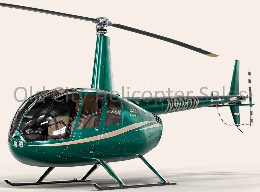
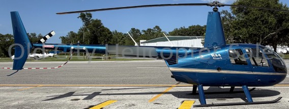
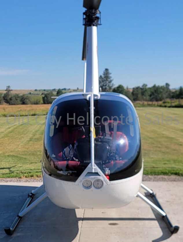
Robinson R44 Raven II for sale now
Free — save the R44 Raven II to your watchlist and track it in one place.
More Robinson R44 Raven IImanuals & documents
See all 45 →- U.S. AIRWORTHINESS DIRECTIVESAirworthiness Directives
- Emergency Checklist R44 RII – Heli Academy V1.0 2025-09Checklist
- R44 SERVICE BULLETIN SB-117Service Bulletins
- ROBINSON MAINTENANCE MANUAL R44 SERIESWiring Diagram
- V-Speeds Reference for the Robinson R44 Raven IIV Speeds Reference
- Advisory Circular: Certification: Pilots and Flight and Ground InstructorsTraining Manual
- ROBINSON MODEL R44 SECTION 5 PERFORMANCEPerformance Data
- Airworthiness Directives; Robinson Helicopter Company HelicoptersAirworthiness Directives
- Collision with terrain involving Robinson R44, VH-OCLOther Documents
- MANDATORY SERVICE BULLETIN - LycomingService Bulletins
- PILOT'S OPERATING HANDBOOK AND FAA APPROVED ROTORCRAFT FLIGHT MANUALPilot's Operating Handbook
- Clutch actuator lower bearing seizure and collision with terrain involving Robinson Helicopter Company R44, VH-KOV near Nathan River Station, Northern Territory on 16 May 2022Other Documents
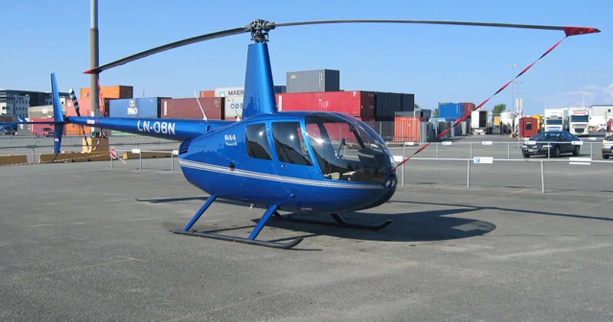
If you fly the Robinson R44 Raven II, you may also be researching these.

In this document
Chapter 1—Introduction to the Helicopter
This chapter introduces the main rotor system, types of rotor systems (fully articulated, semirigid, rigid), antitorque systems, and landing gear configurations. It provides foundational knowledge necessary for understanding helicopter mechanics.
Chapter 5—Helicopter Systems
This section details the various systems within helicopters, including engine types (reciprocating and turbine), fuel systems, electrical systems, and hydraulic systems. It emphasizes the importance of understanding these systems for safe operation and maintenance.
Chapter 8—Performance
This chapter discusses factors affecting helicopter performance such as density altitude, weight, and environmental conditions. It includes performance charts for hovering, takeoff, and climb, which are critical for flight planning and safety.
Chapter 11—Helicopter Emergencies
This section covers emergency procedures including autorotation, power recovery, and handling system malfunctions. It highlights critical safety practices and recovery techniques essential for pilots during in-flight emergencies.
Chapter 12—Attitude Instrument Flying
This chapter focuses on the use of flight instruments, including airspeed indicators and altimeters, and their role in maintaining control during instrument flight. It provides guidance on instrument checks and common errors to avoid.
Safety notes
- Always adhere to operating limitations and emergency procedures outlined in the handbook.
- Understand the implications of density altitude on helicopter performance.
Full document text
ROTORCRAFT FLYING HANDBOOK 2000 U.S. DEPARTMENT OF TRANSPORTATION FEDERAL AVIATION ADMINISTRATION Flight Standards Service i i iii PREFACE The Rotorcraft Flying Handbook is designed as a technical manual for applicants who are preparing for their pri- vate, commercial, or flight instructor pilot certificates with a helicopter or gyroplane class rating. Certificated flight instructors may find this handbook a valuable training aid, since detailed coverage of aerodynamics, flight controls, systems, performance, flight maneuvers, emergencies, and aeronautical decision making is included. Topics, such as weather, navigation, radio navigation and communications, use of flight information publications, and regula- tions are available in other Federal Aviation Administration (FAA) publications. This handbook conforms to pilot training and certification concepts established by the FAA. There are different ways of teaching, as well as performing flight procedures and maneuvers, and many variations in the explanations of aerodynamic theories and principles. This handbook adopts a selective method and concept to flying helicopters and gyroplanes. The discussion and explanations reflect the most commonly used practices and principles. Occasionally, the word “must” or similar language is used where the desired action is deemed critical. The use of such language is not intended to add to, interpret, or relieve a duty imposed by Title 14 of the Code of Federal Regulations (14 CFR). This handbook is divided into two parts. The first part, chapters 1 through 14, covers helicopters, and the second part, chapters 15 through 22, covers gyroplanes. The glossary and index apply to both parts. It is essential for persons using this handbook to also become familiar with and apply the pertinent parts of 14 CFR and the Aeronautical Information Manual (AIM). Performance standards for demonstrating competence required for pilot certification are prescribed in the appropriate rotorcraft practical test standard. This handbook supersedes Advisory Circular (AC) 61-13B, Basic Helicopter Handbook, dated 1978. In addition, all or part of the information contained in the following advisory circulars are included in this handbook: AC 90- 87, Helicopter Dynamic Rollover; AC 90-95, Unanticipated Right Yaw in Helicopters; AC 91-32B, Safety in and around Helicopters; and AC 91-42D, Hazards of Rotating Propeller and Helicopter Rotor Blades. This publication may be purchased from the Superintendent of Documents, U.S. Government Printing Office (GPO), Washington, DC 20402-9325, or from U.S. Government Bookstores located in major cities throughout the United States. The current Flight Standards Service airman training and testing material and subject matter knowledge codes for all airman certificates and ratings can be obtained from the Flight Standards Services web site at http://av-info.faa.gov. Comments regarding this handbook should be sent to U.S. Department of Transportation, Federal Aviation Administration, Airman Testing Standards Branch, AFS-630, P.O. Box 25082, Oklahoma City, OK 73125. AC 00-2, Advisory Circular Checklist, transmits the current status of FAA advisory circulars and other flight infor- mation publications. This checklist is free of charge and may be obtained by sending a request to U.S. Department of Transportation, Subsequent Distribution Office, SVC-121.23, Ardmore East Business Center, 3341 Q 75th Avenue, Landover, MD 20785. AC00-2 also is available on the Internet at http://www.faa.gov/abc/ac-chklst/actoc.htm. iv v Chapter 4—Helicopter Flight Controls Collective Pitch Control ..........................................4-1 Throttle Control.......................................................4-1 Collective Pitch / Throttle Coordination .................4-2 Correlator / Governor ..............................................4-2 Cyclic Pitch Control ................................................4-2 Antitorque Pedals ....................................................4-3 Heading Control..................................................4-3 Chapter 5—Helicopter Systems Engines ....................................................................5-1 Reciprocating Engine..........................................5-1 Turbine Engine....................................................5-1 Compressor.....................................................5-2 Combustion Chamber.....................................5-2 Turbine ...........................................................5-2 Transmission System...............................................5-3 Main Rotor Transmission ...................................5-3 Tail Rotor Drive System .....................................5-3 Clutch..................................................................5-4 Centrifugal Clutch..........................................5-4 Belt Drive Clutch ...........................................5-4 Freewheeling Unit ..........................................5-4 Main Rotor System .................................................5-4 Fully Articulated Rotor System ..........................5-4 Semirigid Rotor System......................................5-5 Rigid Rotor System ............................................5-5 Combination Rotor Systems ...............................5-5 Swash Plate Assembly ........................................5-5 Fuel Systems ...........................................................5-6 Fuel Supply System ............................................5-6 Engine Fuel Control System...............................5-6 Reciprocating Engines ...................................5-7 Carburetor ..................................................5-7 Carburetor Ice ............................................5-7 Fuel Injection.............................................5-8 Turbine Engines .............................................5-8 Electrical Systems ...................................................5-8
Show full textShow less
Hydraulics ...............................................................5-9 Stability Augmentations Systems..........................5-10 Autopilot................................................................5-10 Environmental Systems.........................................5-10 Anti-Icing Systems ................................................5-11 Chapter 6—Rotorcraft Flight Manual (Helicopter) Preliminary Pages....................................................6-1 General Information ................................................6-1 Operating Limitations .............................................6-1 Airspeed Limitation ............................................6-1 Altitude Limitations............................................6-2 Rotor Limitations................................................6-2 HELICOPTER Chapter 1—Introduction to the Helicopter The Main Rotor System ..........................................1-1 Fully Articulated Rotor System ..........................1-1 Semirigid Rotor System......................................1-2 Rigid Rotor System ............................................1-2 Antitorque Systems .................................................1-2 Tail Rotor ............................................................1-2 Fenestron.............................................................1-2 NOTAR® ............................................................1-2 Landing Gear...........................................................1-2 Powerplant...............................................................1-3 Flight Controls.........................................................1-3 Chapter 2—General Aerodynamics Airfoil ......................................................................2-1 Relative Wind .....................................................2-2 Blade Pitch Angle ...............................................2-2 Angle of Attack...................................................2-2 Lift ...........................................................................2-3 Magnus Effect.....................................................2-3 Bernoulli’s Principle ...........................................2-3 Newton’s Third Law of Motion..........................2-4 Weight......................................................................2-4 Thrust.......................................................................2-5 Drag .........................................................................2-5 Profile Drag ........................................................2-5 Induced Drag ......................................................2-5 Parasite Drag.......................................................2-6 Total Drag ...........................................................2-6 Chapter 3—Aerodynamics of Flight Powered Flight ........................................................3-1 Hovering Flight .......................................................3-1 Translating Tendency or Drift.............................3-1 Pendular Action ..................................................3-2 Coning.................................................................3-2 Coriolis Effect (Law of Conservation of Angular Momentum) ..........................................3-2 Ground Effect .....................................................3-3 Gyroscopic Precession........................................3-4 Vertical Flight ..........................................................3-4 Forward Flight.........................................................3-5 Translational Lift ................................................3-5 Induced Flow ......................................................3-6 Transverse Flow Effect .......................................3-6 Dissymmetry of Lift ...........................................3-6 Sideward Flight .......................................................3-8 Rearward Flight.......................................................3-8 Turning Flight..........................................................3-8 Autorotation.............................................................3-8 Autorotation (Vertical Flight) .............................3-9 Autorotation (Forward Flight) ..........................3-11 CONTENTS vi Powerplant Limitations.......................................6-2 Weight and Loading Distribution .......................6-2 Flight Limitations ...............................................6-3 Placards...............................................................6-3 Emergency Procedures ............................................6-3 Normal Procedures ..................................................6-3 Performance.............................................................6-3 Weight and Balance.................................................6-4 Aircraft and Systems Description ...........................6-4 Handling, Servicing, and Maintenance ...................6-4 Supplements ............................................................6-4 Safety and Operational Tips ....................................6-4 Chapter 7—Weight and Balance Weight......................................................................7-1 Basic Empty Weight ...........................................7-1 Useful Load ........................................................7-1 Payload................................................................7-1 Gross Weight.......................................................7-1 Maximum Gross Weight.....................................7-1 Weight Limitations .............................................7-1 Determining Empty Weight ................................7-1 Balance ....................................................................7-2 Center of Gravity ................................................7-2 CG Forward of Forward Limit.......................7-2 CG Aft of Aft Limit .......................................7-2 Lateral Balance ...................................................7-3 Weight and Balance Calculations............................7-3 Reference Datum ................................................7-3 Arm .....................................................................7-4 Moment...............................................................7-4 Center of Gravity Computation ..........................7-4 Weight and Balance Methods..................................7-4 Computational Method .......................................7-4 Loading Chart Method........................................7-5 Sample Problem 1 ..........................................7-5 Sample Problem 2 ..........................................7-5 Sample Problem 3 ..........................................7-6 Combination Method ..........................................7-6 Calculating Lateral CG .......................................7-7 Chapter 8—Performance Factors Affecting Performance................................8-1 Density Altitude ..................................................8-1 Atmospheric Pressure .........................................8-1 Altitude ...............................................................8-2 Temperature ........................................................8-2 Moisture (Humidity) ...........................................8-2 High and Low Density Altitude Conditions .......8-2 Weight .................................................................8-2 Winds ..................................................................8-2 Performance Charts .................................................8-3 Hovering Performance........................................8-3 Sample Problem 1 ..........................................8-4 Sample Problem 2 ..........................................8-4 Takeoff Performance...........................................8-5 Sample Problem 3 ..........................................8-5 Climb Performance .............................................8-5 Sample Problem 4 ..........................................8-6 Chapter 9—Basic Flight Maneuvers Preflight ...................................................................9-1 Minimum Equipment Lists (MELS) and Operations With Inoperative Equipment ............9-1 Engine Start and Rotor Engagement.......................9-2 Rotor Safety Considerations ...............................9-2 Safety In and Around Helicopters ......................9-3 Ramp Attendants and Aircraft Servicing Personnel........................................9-3 Aircraft Servicing...........................................9-3 External-Load Riggers ...................................9-3 Pilot at the Flight Controls.............................9-3 External-Load Hookup Personnel ..................9-3 Passengers ......................................................9-4 Vertical Takeoff to a Hover .....................................9-5 Technique............................................................9-5 Common Errors ..................................................9-5 Hovering ..................................................................9-5 Technique............................................................9-5 Common Errors ..................................................9-5 Hovering Turn .........................................................9-6 Technique............................................................9-6 Common Errors ..................................................9-7 Hovering—Forward Flight......................................9-7 Technique............................................................9-7 Common Errors ..................................................9-7 Hovering—Sideward Flight ....................................9-7 Technique............................................................9-7 Common Errors ..................................................9-8 Hovering—Rearward Flight....................................9-8 Technique............................................................9-8 Common Errors ..................................................9-8 Taxiing.....................................................................9-8 Hover Taxi ..........................................................9-9 Air Taxi ...............................................................9-9 Technique .......................................................9-9 Common Errors..............................................9-9 Surface Taxi ........................................................9-9 Technique .......................................................9-9 Common Errors............................................9-10 Normal Takeoff From a Hover..............................9-10 Technique..........................................................9-10 Common Errors ................................................9-10 Normal Takeoff From the Surface.........................9-11 Technique ..........................................................9-11 Common Errors.................................................9-11 Crosswind Considerations During Takeoffs ................................................9-11 Straight-and-Level Flight ......................................9-12 vii Technique..........................................................9-12 Common Errors ................................................9-12 Turns......................................................................9-12 Technique..........................................................9-12 Slips ..................................................................9-13 Skids..................................................................9-13 Common Errors ................................................9-13 Normal Climb........................................................9-13 Technique..........................................................9-13 Common Errors ................................................9-14 Normal Descent.....................................................9-14 Technique..........................................................9-14 Common Errors ................................................9-14 Ground Reference Maneuvers...............................9-14 Rectangular Course...........................................9-14 S-Turns..............................................................9-16 Turns Around a Point........................................9-17 Common Errors During Ground Reference Maneuvers .......................................9-18 Traffic Patterns ......................................................9-18 Approaches ............................................................9-19 Normal Approach to a Hover ...........................9-19 Technique .....................................................9-19 Common Errors............................................9-19 Normal Approach to the Surface ......................9-20 Technique .....................................................9-20 Common Errors............................................9-20 Crosswind During Approaches .........................9-20 Go-Around.............................................................9-20 After Landing and Securing ..................................9-20 Noise Abatement Procedures ................................9-20 Chapter 10—Advanced Maneuvers Reconnaissance Procedures...................................10-1 High Reconnaissance........................................10-1 Low Reconnaissance ........................................10-1 Ground Reconnaissance....................................10-1 Maximum Performance Takeoff ...........................10-2 Technique..........................................................10-2 Common Errors ................................................10-2 Running/Rolling Takeoff.......................................10-2 Technique..........................................................10-3 Common Errors ................................................10-3 Rapid Deceleration (Quick Stop) ..........................10-3 Technique..........................................................10-3 Common Errors ................................................10-4 Steep Approach to a Hover ...................................10-4 Technique..........................................................10-4 Common Errors ................................................10-5 Shallow Approach and Running/Roll-On Landing..................................................................10-5 Technique..........................................................10-5 Common Errors ................................................10-5 Slope Operations ...................................................10-6 Slope Landing ...................................................10-6 Technique.....................................................10-6 Common Errors............................................10-6 Slope Takeoff ....................................................10-6 Technique.....................................................10-7 Common Errors............................................10-7 Confined Area Operations.....................................10-7 Approach...........................................................10-7 Takeoff ..............................................................10-8 Common Errors ................................................10-8 Pinnacle and Ridgeline Operations .......................10-8 Approach and Landing .....................................10-8 Takeoff ..............................................................10-9 Common Errors ................................................10-9 Chapter 11—Helicopter Emergencies Autorotation...........................................................11-1 Straight-in Autorotation ....................................11-2 Technique .....................................................11-2 Common Errors............................................11-3 Power Recovery From Practice Autorotation ......................................................11-3 Technique .....................................................11-3 Common Errors............................................11-3 Autorotation With Turns ...................................11-3 Technique .....................................................11-3 Power Failure in a Hover..................................11-4 Technique .....................................................11-4 Common Errors............................................11-4 Height/Velocity Diagram.......................................11-4 The Effect of Weight Versus Density Altitude ................................................11-5 Vortex Ring State (Settling With Power) ..............11-5 Retreating Blade Stall............................................11-6 Ground Resonance.................................................11-7 Dynamic Rollover .................................................11-7 Critical Conditions ............................................11-8 Cyclic Trim .......................................................11-8 Normal Takeoffs and Landings.........................11-8 Slope Takeoffs and Landings............................11-8 Use of Collective ..............................................11-9 Precautions ........................................................11-9 Low G Conditions and Mast Bumping ...............11-10 Low Rotor RPM and Blade Stall ........................11-10 Recovery From Low Rotor RPM........................11-10 Systems Malfunctions..........................................11-11 Antitorque System Failure ..............................11-11 Landing—Stuck Left Pedal........................11-11 Landing—Stuck Neutral or Right Pedal .................................................11-12 Unanticipated Yaw / Loss of Tail Rotor Effectiveness (LTE) ........................................11-12 Main Rotor Disc Interference (285-315°) .......................................................11-12 Weathercock Stability (120-240°) .......................................................11-13 viii Tail Rotor Vortex Ring State (210-330°) .......................................................11-13 LTE at Altitude...........................................11-13 Reducing the Onset of LTE .......................11-13 Recovery Technique...................................11-14 Main Drive Shaft Failure ................................11-14 Hydraulic Failures...........................................11-14 Governor Failure.............................................11-14 Abnormal Vibrations.......................................11-14 Low Frequency Vibrations.........................11-15 Medium and High Frequency Vibrations ...................................................11-15 Tracking and Balance ................................11-15 Flight Diversion...................................................11-15 Lost Procedures ...................................................11-16 Emergency Equipment and Survival Gear ..........11-16 Chapter 12—Attitude Instrument Flying Flight Instruments .................................................12-1 Pitot-Static Instruments ....................................12-1 Airspeed Indicator........................................12-1 Instrument Check.........................................12-1 Altimeter ......................................................12-2 Instrument Check.....................................12-2 Vertical Speed Indicator....................................12-2 Instrument Check.........................................12-2 System Errors...............................................12-2 Gyroscopic Instruments ....................................12-3 Attitude Indicator.........................................12-3 Heading Indicator ........................................12-3 Turn Indicators.............................................12-4 Instrument Check.........................................12-4 Magnetic Compass............................................12-4 Compass Errors............................................12-4 Magnetic Variation.......................................12-4 Compass Deviation..................................12-5 Magnetic Dip ...........................................12-5 Instrument Check.....................................12-5 Instrument Flight ...................................................12-5 Instrument Cross-Check ...................................12-5 Instrument Interpretation ..................................12-6 Aircraft Control ................................................12-7 Straight-and-Level Flight..................................12-7 Pitch Control ................................................12-7 Attitude Indicator.....................................12-8 Altimeter ..................................................12-8 Vertical Speed Indicator ..........................12-8 Airspeed Indicator ...................................12-9 Bank Control................................................12-9 Attitude Indicator.....................................12-9 Heading Indicator ..................................12-10 Turn Indicator ........................................12-10 Common Errors During Straight-and-Level Flight ...........................12-10 Power Control During Straight-and-Level Flight ...........................12-11 Common Errors During Airspeed Changes.......................................12-11 Straight Climbs (Constant Airspeed and Constant Rate)..........................................12-11 Entry...........................................................12-12 Leveloff......................................................12-14 Straight Descents (Constant Airspeed and Constant Rate) ................................................12-14 Entry...........................................................12-14 Leveloff......................................................12-15 Common Errors During Straight Climbs and Descents ....................12-15 Turns ...............................................................12-15 Turns to a Predetermined Heading ............12-16 Timed Turns ...............................................12-16 Change of Airspeed in Turns .................12-16 30° Bank Turn............................................12-17 Climbing and Descending Turns ...............12-17 Compass Turns...........................................12-17 Common Errors During Turns...................12-18 Unusual Attitudes............................................12-18 Common Errors During Unusual Attitude Recoveries ....................................12-18 Emergencies ........................................................12-18 Autorotations ..................................................12-19 Common Errors During Autorotations..............................................12-19 Servo Failure...................................................12-19 Instrument Takeoff ..............................................12-19 Common Errors During Instrument Takeoffs ........................................12-20 Chapter 13—Night Operations Night Flight Physiology ........................................13-1 Vision in Flight .................................................13-1 The Eye .............................................................13-1 Cones ................................................................13-1 Rods ..................................................................13-2 Night Vision......................................................13-2 Night Scanning .................................................13-2 Aircraft Lighting ...............................................13-3 Visual Illusions .................................................13-3 Autokinesis ..................................................13-3 Night Myopia...............................................13-3 False Horizon...............................................13-3 Landing Illusions .........................................13-4 Night Flight ...........................................................13-4 Preflight ............................................................13-4 Engine Starting and Rotor Engagement ...........13-4 Taxi Technique..................................................13-4 Takeoff ..............................................................13-4 En route Procedures..........................................13-5 ix Collision Avoidance at Night............................13-5 Approach and Landing .....................................13-5 Chapter 14—Aeronautical Decision Making Origins of ADM Training......................................14-2 The Decision-Making Process ..............................14-3 Defining the Problem........................................14-3 Choosing a Course of Action............................14-3 Implementing the Decision and Evaluating the Outcome ...................................14-3 Risk Management..................................................14-4 Assessing Risk ..................................................14-4 Factors Affecting Decision Making ......................14-5 Pilot Self-Assessment .......................................14-5 Recognizing Hazardous Attitudes ....................14-5 Stress management ...........................................14-6 Use of Resources ..............................................14-6 Internal Resources ........................................14-7 External Resources.......................................14-7 Workload Management.....................................14-7 Situational Awareness .......................................14-8 Obstacles to Maintaining Situational Awareness ..................................14-8 Operational Pitfalls.......................................14-8 GYROPLANE Chapter 15—Introduction to the Gyroplane Types of Gyroplanes..............................................15-1 Components...........................................................15-2 Airframe............................................................15-2 Powerplant ........................................................15-2 Rotor System ....................................................15-2 Tail Surfaces .....................................................15-2 Landing Gear ....................................................15-3 Wings ................................................................15-3 Chapter 16—Aerodynamics of the Gyroplane Autorotation...........................................................16-1 Vertical Autorotation.........................................16-1 Rotor Disc Regions...........................................16-2 Autorotation in Forward Flight ........................16-2 Reverse Flow................................................16-3 Retreating Blade Stall ..................................16-3 Rotor Force............................................................16-3 Rotor Lift ..........................................................16-4 Rotor Drag ........................................................16-4 Thrust.....................................................................16-4 Stability .................................................................16-5 Horizontal Stabilizer .........................................16-5 Fuselage Drag (Center of Pressure)..................16-5 Pitch Inertia.......................................................16-5 Propeller Thrust Line........................................16-5 Rotor Force .......................................................16-6 Trimmed Condition...........................................16-6 Chapter 17—Gyroplane Flight Controls Cyclic Control .......................................................17-1 Throttle ..................................................................17-1 Rudder ...................................................................17-2 Horizontal Tail Surfaces........................................17-2 Collective Control .................................................17-2 Chapter 18—Gyroplane Systems Propulsion Systems ...............................................18-1 Rotor Systems .......................................................18-1 Semirigid Rotor System....................................18-1 Fully Articulated Rotor System ........................18-1 Prerotator ...............................................................18-2 Mechanical Prerotator.......................................18-2 Hydraulic Prerotator .........................................18-2 Electric Prerotator .............................................18-3 Tip Jets ..............................................................18-3 Instrumentation......................................................18-3 Engine Instruments ...........................................18-3 Rotor Tachometer .............................................18-3 Slip/Skid Indicator ............................................18-4 Airspeed Indicator ............................................18-4 Altimeter ...........................................................18-4 IFR Flight Instrumentation ...............................18-4 Ground Handling...................................................18-4 Chapter 19—Rotorcraft Flight Manual (Gyroplane) Using the Flight Manual........................................19-1 Weight and Balance Section .............................19-1 Sample Problem ...........................................19-1 Performance Section .........................................19-2 Sample Problem ...........................................19-2 Height/Velocity Diagram .............................19-3 Emergency Section ...........................................19-3 Hang Test...............................................................19-4 Chapter 20—Flight Operations Preflight .................................................................20-1 Cockpit Management........................................20-1 Engine Starting ......................................................20-1 Taxiing...................................................................20-1 Blade Flap .........................................................20-1 Before Takeoff.......................................................20-2 Prerotation.........................................................20-2 Takeoff...................................................................20-3 Normal Takeoff.................................................20-3 Crosswind Takeoff ............................................20-4 Common Errors for Normal and Crosswind Takeoffs ..........................................20-4 Short-Field Takeoff...........................................20-4 x Common Errors............................................20-4 High-Altitude Takeoff ..................................20-4 Soft-Field Takeoff.............................................20-5 Common Errors............................................20-5 Jump Takeoff................................................20-5 Basic Flight Maneuvers.........................................20-6 Straight-and-Level Flight..................................20-6 Climbs...............................................................20-6 Descents ............................................................20-7 Turns .................................................................20-7 Slips..............................................................20-7 Skids .............................................................20-7 Common Errors During Basic Flight Maneuvers ..............................................20-8 Steep Turns .......................................................20-8 Common Errors............................................20-8 Ground Reference Maneuvers...............................20-8 Rectangular Course...........................................20-8 S-Turns............................................................20-10 Turns Around a Point......................................20-11 Common Errors During Ground Reference Maneuvers ........................20-11 Flight at Slow Airspeeds .....................................20-12 Common Errors ..............................................20-12 High Rate of Descent ..........................................20-12 Common Errors ..............................................20-13 Landings ..............................................................20-13 Normal Landing..............................................20-13 Short-Field Landing........................................20-13 Soft-Field Landing..........................................20-14 Crosswind Landing .........................................20-14 High-Altitude Landing....................................20-14 Common Errors During Landing....................20-15 Go-Around...........................................................20-15 Common Errors ..............................................20-15 After Landing and Securing ................................20-15 Chapter 21—Gyroplane Emergencies Aborted Takeoff.....................................................21-1 Accelerate/Stop Distance..................................21-1 Lift-off at Low Airspeed and High Angle of Attack ............................................21-1 Common Errors ................................................21-2 Pilot-Induced Oscillation (PIO) ............................21-2 Buntover (Power Pushover) ..................................21-3 Ground Resonance ................................................21-3 Emergency Approach and Landing .......................21-3 Emergency Equipment and Survival Gear............21-4 Chapter 22—Gyroplane Aeronautical Decision Making Impulsivity.............................................................22-1 Invulnerability .......................................................22-1 Macho ....................................................................22-2 Resignation ............................................................22-2 Anti-Authority .......................................................22-3 Glossary.................................................................G-1 Index........................................................................I-1 1-1 Helicopters come in many sizes and shapes, but most share the same major components. These components include a cabin where the payload and crew are car- ried; an airframe, which houses the various compo- nents, or where components are attached; a powerplant or engine; and a transmission, which, among other things, takes the power from the engine and transmits it to the main rotor, which provides the aerodynamic forces that make the helicopter fly. Then, to keep the helicopter from turning due to torque, there must be some type of antitorque system. Finally there is the landing gear, which could be skids, wheels, skis, or floats. This chapter is an introduction to these compo- nents. [Figure 1-1] THE MAIN ROTOR SYSTEM The rotor system found on helicopters can consist of a single main rotor or dual rotors. With most dual rotors, the rotors turn in opposite directions so the torque from one rotor is opposed by the torque of the other. This cancels the turning tendencies. [Figure 1-2] In general, a rotor system can be classified as either fully articulated, semirigid, or rigid. There are varia- tions and combinations of these systems, which will be discussed in greater detail in Chapter 5—Helicopter Systems. FULLY ARTICULATED ROTOR SYSTEM A fully articulated rotor system usually consists of three or more rotor blades. The blades are allowed to flap, feather, and lead or lag independently of each other. Each rotor blade is attached to the rotor hub by a horizontal hinge, called the flapping hinge, which per- mits the blades to flap up and down. Each blade can move up and down independently of the others. The flapping hinge may be located at varying distances from the rotor hub, and there may be more than one. The position is chosen by each manufacturer, primarily with regard to stability and control. Payload—The term used for pas- sengers, baggage, and cargo. Torque—In helicopters with a sin- gle, main rotor system, the ten- dency of the helicopter to turn in the opposite direction of the main rotor rotation. Blade Flap—The upward or downward movement of the rotor blades during rotation. Blade Feather or Feathering—The rotation of the blade around the spanwise (pitch change) axis. Blade Lead or Lag—The fore and aft movement of the blade in the plane of rotation. It is sometimes called hunting or dragging. Landing Gear Tail Rotor System Main Rotor System Cabin Airframe Transmission Powerplant Figure 1-2. Helicopters can have a single main rotor or a dual rotor system. Figure 1-1. The major components of a helicopter are the cabin, airframe, landing gear, powerplant, transmission, main rotor system, and tail rotor system. 1-2 Each rotor blade is also attached to the hub by a verti- cal hinge, called a drag or lag hinge, that permits each blade, independently of the others, to move back and forth in the plane of the rotor disc. Dampers are nor- mally incorporated in the design of this type of rotor system to prevent excessive motion about the drag hinge. The purpose of the drag hinge and dampers is to absorb the acceleration and deceleration of the rotor blades. The blades of a fully articulated rotor can also be feath- ered, or rotated about their spanwise axis. To put it more simply, feathering means the changing of the pitch angle of the rotor blades. SEMIRIGID ROTOR SYSTEM A semirigid rotor system allows for two different movements, flapping and feathering. This system is normally comprised of two blades, which are rigidly attached to the rotor hub. The hub is then attached to the rotor mast by a trunnion bearing or teetering hinge. This allows the blades to see-saw or flap together. As one blade flaps down, the other flaps up. Feathering is accomplished by the feathering hinge, which changes the pitch angle of the blade. RIGID ROTOR SYSTEM The rigid rotor system is mechanically simple, but structurally complex because operating loads must be absorbed in bending rather than through hinges. In this system, the blades cannot flap or lead and lag, but they can be feathered. ANTITORQUE SYSTEMS TAIL ROTOR Most helicopters with a single, main rotor system require a separate rotor to overcome torque. This is accomplished through a variable pitch, antitorque rotor or tail rotor. [Figure 1-3]. You will need to vary the thrust of the antitorque system to maintain directional control whenever the main rotor torque changes, or to make heading changes while hovering. FENESTRON Another form of antitorque rotor is the fenestron or “fan-in-tail” design. This system uses a series of rotat- ing blades shrouded within a vertical tail. Because the blades are located within a circular duct, they are less likely to come into contact with people or objects. [Figure 1-4] NOTAR® The NOTAR® system is an alternative to the antitorque rotor. The system uses low-pressure air that is forced into the tailboom by a fan mounted within the helicop- ter. The air is then fed through horizontal slots, located on the right side of the tailboom, and to a controllable rotating nozzle to provide antitorque and directional control. The low-pressure air coming from the horizon- tal slots, in conjunction with the downwash from the main rotor, creates a phenomenon called “Coanda Effect,” which produces a lifting force on the right side of the tailboom. [Figure 1-5] LANDING GEAR The most common landing gear is a skid type gear, which is suitable for landing on various types of sur- faces. Some types of skid gear are equipped with dampers so touchdown shocks or jolts are not transmit- ted to the main rotor system. Other types absorb the shocks by the bending of the skid attachment arms. Landing skids may be fitted with replaceable heavy- duty skid shoes to protect them from excessive wear and tear. Helicopters can also be equipped with floats for water operations, or skis for landing on snow or soft terrain. Wheels are another type of landing gear. They may be in a tricycle or four point configuration. Normally, the Tail Rotor Thrust to Compensate for Torque Torque Torque Blade Rotation Figure 1-3. The antitorque rotor produces thrust to oppose torque and helps prevent the helicopter from turning in the opposite direction of the main rotor. Figure 1-4. Compared to an unprotected tail rotor, the fene- stron antitorque system provides an improved margin of safety during ground operations. 1-3 nose or tail gear is free to swivel as the helicopter is taxied on the ground. POWERPLANT A typical small helicopter has a reciprocating engine, which is mounted on the airframe. The engine can be mounted horizontally or vertically with the transmis- sion supplying the power to the vertical main rotor shaft. [Figure 1-6] Another engine type is the gas turbine. This engine is used in most medium to heavy lift helicopters due to its large horsepower output. The engine drives the main transmission, which then transfers power directly to the main rotor system, as well as the tail rotor. FLIGHT CONTROLS When you begin flying a helicopter, you will use four basic flight controls. They are the cyclic pitch control; the collective pitch control; the throttle, which is usually a twist grip control located on the end of the collective lever; and the antitorque pedals. The col- lective and cyclic controls the pitch of the main rotor blades. The function of these controls will be explained in detail in Chapter 4—Flight Controls. [Figure 1-7] Figure 1-5. While in a hover, Coanda Effect supplies approxi- mately two-thirds of the lift necessary to maintain directional control. The rest is created by directing the thrust from the controllable rotating nozzle. Main Rotor Wake Rotating Nozzle Downwash Air Jet Lift Air Intake Main Rotor Main Transmission Antitorque Rotor Engine Figure 1-6. Typically, the engine drives the main rotor through a transmission and belt drive or centrifugal clutch system. The antitorque rotor is driven from the transmission. Cyclic Throttle Collective Antitorque Pedals Figure 1-7. Location of flight controls. 1-4 2-1 There are four forces acting on a helicopter in flight. They are lift, weight, thrust, and drag. [Figure 2-1] Lift is the upward force created by the effect of airflow as it passes around an airfoil. Weight opposes lift and is caused by the downward pull of gravity. Thrust is the force that propels the helicopter through the air. Opposing lift and thrust is drag, which is the retarding force created by development of lift and the movement of an object through the air. AIRFOIL Before beginning the discussion of lift, you need to be aware of certain aerodynamic terms that describe an airfoil and the interaction of the airflow around it. An airfoil is any surface, such as an airplane wing or a helicopter rotor blade, which provides aerodynamic force when it interacts with a moving stream of air. Although there are many different rotor blade airfoil designs, in most helicopter flight conditions, all airfoils perform in the same manner. Engineers of the first helicopters designed relatively thick airfoils for their structural characteristics. Because the rotor blades were very long and slender, it was necessary to incorporate more structural rigidity into them. This prevented excessive blade droop when the rotor system was idle, and minimized blade twist- ing while in flight. The airfoils were also designed to be symmetrical, which means they had the same cam- ber (curvature) on both the upper and lower surfaces. Symmetrical blades are very stable, which helps keep blade twisting and flight control loads to a minimum. [Figure 2-2] This stability is achieved by keeping the center of pressure virtually unchanged as the angle of attack changes. Center of pressure is the imaginary point on the chord line where the resultant of all aero- dynamic forces are considered to be concentrated. Today, designers use thinner airfoils and obtain the required rigidity by using composite materials. In addi- tion, airfoils are asymmetrical in design, meaning the upper and lower surface do not have the same camber. Normally these airfoils would not be as stable, but this can be corrected by bending the trailing edge to produce the same characteristics as symmetrical airfoils. This is called “reflexing.” Using this type of rotor blade allows the rotor system to operate at higher forward speeds. One of the reasons an asymmetrical rotor blade is not as stable is that the center of pressure changes with changes in angle of attack. When the center of pressure lifting force is behind the pivot point on a rotor blade, it tends to cause the rotor disc to pitch up. As the angle of attack increases, the center of pressure moves forward. If it moves ahead of the pivot point, the pitch of the rotor disc decreases. Since the angle of attack of the rotor blades is constantly changing during each cycle of rotation, the blades tend to flap, feather, lead, and lag to a greater degree. When referring to an airfoil, the span is the distance from the rotor hub to the blade tip. Blade twist refers to a changing chord line from the blade root to the tip. Figure 2-2. The upper and lower curvatures are the same on a symmetrical airfoil and vary on an asymmetrical airfoil. Asymmetrical Symmetrical Lift Weight Drag Thrust Figure 2-1. Four forces acting on a helicopter in forward flight. 2-2 Twisting a rotor blade causes it to produce a more even amount of lift along its span. This is necessary because rotational velocity increases toward the blade tip. The leading edge is the first part of the airfoil to meet the oncoming air. [Figure 2-3] The trailing edge is the aft portion where the airflow over the upper surface joins the airflow under the lower surface. The chord line is an imaginary straight line drawn from the leading to the trailing edge. The camber is the curvature of the air- foil’s upper and lower surfaces. The relative wind is the wind moving past the airfoil. The direction of this wind is relative to the attitude, or position, of the airfoil and is always parallel, equal, and opposite in direction to the flight path of the airfoil. The angle of attack is the angle between the blade chord line and the direction of the relative wind. RELATIVE WIND Relative wind is created by the motion of an airfoil through the air, by the motion of air past an airfoil, or by a combination of the two. Relative wind may be affected by several factors, including the rotation of the rotor blades, horizontal movement of the helicopter, flapping of the rotor blades, and wind speed and direction. For a helicopter, the relative wind is the flow of air with respect to the rotor blades. If the rotor is stopped, wind blowing over the blades creates a relative wind. When the helicopter is hovering in a no-wind condition, rela- tive wind is created by the motion of the rotor blades through the air. If the helicopter is hovering in a wind, the relative wind is a combination of the wind and the motion of the rotor blades through the air. When the helicopter is in forward flight, the relative wind is a combination of the rotation of the rotor blades and the forward speed of the helicopter. BLADE PITCH ANGLE The pitch angle of a rotor blade is the angle between its chord line and the reference plane containing the rotor hub. [Figure 2-4] You control the pitch angle of the blades with the flight controls. The collective pitch changes each rotor blade an equal amount of pitch no matter where it is located in the plane of rotation (rotor disc) and is used to change rotor thrust. The cyclic pitch control changes the pitch of each blade as a function of where it is in the plane of rotation. This allows for trimming the helicopter in pitch and roll during forward flight and for maneuvering in all flight conditions. ANGLE OF ATTACK When the angle of attack is increased, air flowing over the airfoil is diverted over a greater distance, resulting in an increase of air velocity and more lift. As angle of attack is increased further, it becomes more difficult for air to flow smoothly across the top of the airfoil. At this point the airflow begins to separate from the airfoil and enters a burbling or turbulent pattern. The turbulence results in a large increase in drag and loss of lift in the area where it is taking place. Increasing the angle of attack increases lift until the critical angle of attack is reached. Any increase in the angle of attack beyond this point produces a stall and a rapid decrease in lift. [Figure 2-5] Angle of attack should not be confused with pitch angle. Pitch angle is determined by the direction of the relative wind. You can, however, change the angle of attack by changing the pitch angle through the use of the flight controls. If the pitch angle is increased, the angle of attack is increased, if the pitch angle is reduced, the angle of attack is reduced. [Figure 2-6] Axis-of-Rotation—The imaginary line about which the rotor rotates. It is represented by a line drawn through the center of, and perpen- dicular to, the tip-path plane. Tip-Path Plane—The imaginary circular plane outlined by the rotor blade tips as they make a cycle of rotation. Aircraft Pitch—When referenced to a helicopter, is the movement of the helicopter about its lateral, or side to side axis. Movement of the cyclic forward or aft causes the nose of the helicopter to move up or down. Aircraft Roll—Is the movement of the helicopter about its longitudi- nal, or nose to tail axis. Movement of the cyclic right or left causes the helicopter to tilt in that direction. Figure 2-3. Aerodynamic terms of an airfoil. Trailing Edge Chord Line Angle of Attack FLIGHT PATH RELATIVE WIND Upper Camber Lower Camber Leading Edge Axis of Rotation Reference Plane Pitch Angle Chord Line Figure 2-4. Do not confuse the axis of rotation with the rotor mast. The only time they coincide is when the tip-path plane is perpendicular to the rotor mast. 2-3 LIFT MAGNUS EFFECT The explanation of lift can best be explained by looking at a cylinder rotating in an airstream. The local velocity near the cylinder is composed of the airstream velocity and the cylinder’s rotational velocity, which decreases with distance from the cylinder. On a cylinder, which is rotating in such a way that the top surface area is rotating in the same direction as the airflow, the local velocity at the surface is high on top and low on the bottom. As shown in figure 2-7, at point “A,” a stagnation point exists where the airstream line that impinges on the sur- face splits; some air goes over and some under. Another stagnation point exists at “B,” where the two air streams rejoin and resume at identical velocities. We now have upwash ahead of the rotating cylinder and downwash at the rear. The difference in surface velocity accounts for a differ- ence in pressure, with the pressure being lower on the top than the bottom. This low pressure area produces an upward force known as the “Magnus Effect.” This mechanically induced circulation illustrates the rela- tionship between circulation and lift. An airfoil with a positive angle of attack develops air circulation as its sharp trailing edge forces the rear stagnation point to be aft of the trailing edge, while the front stagnation point is below the leading edge. [Figure 2-8] BERNOULLI’S PRINCIPLE Air flowing over the top surface accelerates. The airfoil is now subjected to Bernoulli’s Principle or the “venturi effect.” As air velocity increases through the constricted portion of a venturi tube, the pressure decreases. Axis of Rotation Reference Plane Pitch Angle Chord Line Angle of Attack RELATIVE WIND Figure 2-6. Angle of attack may be greater than, less than, or the same as the pitch angle. Figure 2-5. As the angle of attack is increased, the separation point starts near the trailing edge of the airfoil and pro- gresses forward. Finally, the airfoil loses its lift and a stall condition occurs. LIFT STALL 8° 12-16° Figure 2-7. Magnus Effect is a lifting force produced when a rotating cylinder produces a pressure differential. This is the same effect that makes a baseball curve or a golf ball slice. B A Increased Local Velocity (Decreased pressure) Decreased Local Velocity Downwash Upwash Figure 2-8. Air circulation around an airfoil occurs when the front stagnation point is below the leading edge and the aft stagnation point is beyond the trailing edge. Leading Edge Stagnation Point Trailing Edge Stagnation Point B A Steady-State Flight—A condition when an aircraft is in straight- and-level, unaccelerated flight, and all forces are in balance. 2-4 ward. According to Newton’s Third Law of Motion, “for every action there is an equal and opposite reac- tion,” the air that is deflected downward also produces an upward (lifting) reaction. Since air is much like water, the explanation for this source of lift may be compared to the planing effect of skis on water. The lift which supports the water skis (and the skier) is the force caused by the impact pres- sure and the deflection of water from the lower surfaces of the skis. Under most flying conditions, the impact pressure and the deflection of air from the lower surface of the rotor blade provides a comparatively small percentage of the total lift. The majority of lift is the result of decreased pressure above the blade, rather than the increased pressure below it. WEIGHT Normally, weight is thought of as being a known, fixed value, such as the weight of the helicopter, fuel, and occupants. To lift the helicopter off the ground verti- cally, the rotor system must generate enough lift to overcome or offset the total weight of the helicopter and its occupants. This is accomplished by increasing the pitch angle of the main rotor blades. The weight of the helicopter can also be influenced by aerodynamic loads. When you bank a helicopter while maintaining a constant altitude, the “G” load or load factor increases. Load factor is the ratio of the load sup- ported by the main rotor system to the actual weight of the helicopter and its contents. In steady-state flight, the helicopter has a load factor of one, which means the main rotor system is supporting the actual total weight of the helicopter. If you increase the bank angle to 60°, while still maintaining a constant altitude, the load fac- tor increases to two. In this case, the main rotor system has to support twice the weight of the helicopter and its contents. [Figure 2-11] Disc loading of a helicopter is the ratio of weight to the total main rotor disc area, and is determined by divid- ing the total helicopter weight by the rotor disc area, which is the area swept by the blades of a rotor. Disc area can be found by using the span of one rotor blade as the radius of a circle and then determining the area the blades encompass during a complete rotation. As the helicopter is maneuvered, disc loading changes. The higher the loading, the more power you need to maintain rotor speed. Leading Edge Stagnation Point B A Compare the upper surface of an airfoil with the con- striction in a venturi tube that is narrower in the middle than at the ends. [Figure 2-9] The upper half of the venturi tube can be replaced by layers of undisturbed air. Thus, as air flows over the upper surface of an airfoil, the camber of the airfoil causes an increase in the speed of the airflow. The increased speed of airflow results in a decrease in pres- sure on the upper surface of the airfoil. At the same time, air flows along the lower surface of the airfoil, building up pressure. The combination of decreased pressure on the upper surface and increased pressure on the lower surface results in an upward force. [Figure 2-10] As angle of attack is increased, the production of lift is increased. More upwash is created ahead of the airfoil as the leading edge stagnation point moves under the leading edge, and more downwash is created aft of the trailing edge. Total lift now being produced is perpen- dicular to relative wind. In summary, the production of lift is based upon the airfoil creating circulation in the airstream (Magnus Effect) and creating differential pressure on the airfoil (Bernoulli’s Principle). NEWTON’S THIRD LAW OF MOTION Additional lift is provided by the rotor blade’s lower surface as air striking the underside is deflected down- Figure 2-10. Lift is produced when there is decreased pres- sure above and increased pressure below an airfoil. Lift Decreased Pressure Increased Pressure Increased Velocity Decreased Pressure Figure 2-9. The upper surface of an airfoil is similar to the constriction in a venturi tube. 2-5 DRAG The force that resists the movement of a helicopter through the air and is produced when lift is developed is called drag. Drag always acts parallel to the relative wind. Total drag is composed of three types of drag: profile, induced, and parasite. PROFILE DRAG Profile drag develops from the frictional resistance of the blades passing through the air. It does not change significantly with the airfoil’s angle of attack, but increases moderately when airspeed increases. Profile drag is composed of form drag and skin friction. Form drag results from the turbulent wake caused by the separation of airflow from the surface of a struc- ture. The amount of drag is related to both the size and shape of the structure that protrudes into the relative wind. [Figure 2-12] Skin friction is caused by surface roughness. Even though the surface appears smooth, it may be quite rough when viewed under a microscope. A thin layer of air clings to the rough surface and creates small eddies that contribute to drag. INDUCED DRAG Induced drag is generated by the airflow circulation around the rotor blade as it creates lift. The high-pres- sure area beneath the blade joins the low-pressure air above the blade at the trailing edge and at the rotor tips. This causes a spiral, or vortex, which trails behind each blade whenever lift is being produced. These vortices deflect the airstream downward in the vicinity of the blade, creating an increase in downwash. Therefore, the blade operates in an average relative wind that is inclined downward and rearward near the blade. Because the lift produced by the blade is perpendicular Aircraft Yaw—The movement of the helicopter about its vertical axis. THRUST Thrust, like lift, is generated by the rotation of the main rotor system. In a helicopter, thrust can be for- ward, rearward, sideward, or vertical. The resultant of lift and thrust determines the direction of movement of the helicopter. The solidity ratio is the ratio of the total rotor blade area, which is the combined area of all the main rotor blades, to the total rotor disc area. This ratio provides a means to measure the potential for a rotor system to provide thrust. The tail rotor also produces thrust. The amount of thrust is variable through the use of the antitorque ped- als and is used to control the helicopter’s yaw. Figure 2-11. The load factor diagram allows you to calculate the amount of “G” loading exerted with various angle of bank. Load Factor - "G's" Bank Angle (in Degrees) 0 10 20 30 40 50 60 70 80 90 9 8 7 6 5 4 3 2 1 0 Figure 2-12. It is easy to visualize the creation of form drag by examining the airflow around a flat plate. Streamlining decreases form drag by reducing the airflow separation. 2-6 to the relative wind, the lift is inclined aft by the same amount. The component of lift that is acting in a rear- ward direction is induced drag. [Figure 2-13] As the air pressure differential increases with an increase in angle of attack, stronger vortices form, and induced drag increases. Since the blade’s angle of attack is usually lower at higher airspeeds, and higher at low speeds, induced drag decreases as airspeed increases and increases as airspeed decreases. Induced drag is the major cause of drag at lower airspeeds. PARASITE DRAG Parasite drag is present any time the helicopter is moving through the air. This type of drag increases with airspeed. Nonlifting components of the helicopter, such as the cabin, rotor mast, tail, and landing gear, contribute to par- asite drag. Any loss of momentum by the airstream, due to such things as openings for engine cooling, creates additional parasite drag. Because of its rapid increase with increasing airspeed, parasite drag is the major cause of drag at higher airspeeds. Parasite drag varies with the square of the velocity. Doubling the airspeed increases the parasite drag four times. TOTAL DRAG Total drag for a helicopter is the sum of all three drag forces. [Figure 2-14] As airspeed increases, parasite drag increases, while induced drag decreases. Profile drag remains relatively constant throughout the speed range with some increase at higher airspeeds. Combining all drag forces results in a total drag curve. The low point on the total drag curve shows the air- speed at which drag is minimized. This is the point where the lift-to-drag ratio is greatest and is referred to as L/D max. At this speed, the total lift capacity of the helicopter, when compared to the total drag of the heli- copter, is most favorable. This is important in helicopter performance. Figure 2-14. The total drag curve represents the combined forces of parasite, profile, and induced drag; and is plotted against airspeed. 0 25 50 75 100 125 150 Speed Drag Parasite Drag Profile Drag Induced Drag Total Drag Minimum Drag or L/D max L/Dmax—The maximum ratio between total lift (L) and the total drag (D). This point provides the best glide speed. Any deviation from best glide speed increases drag and reduces the distance you can glide. Induced Drag Figure 2-13. The formation of induced drag is associated with the downward deflection of the airstream near the rotor blade. 3-1 Once a helicopter leaves the ground, it is acted upon by the four aerodynamic forces. In this chapter, we will examine these forces as they relate to flight maneuvers. POWERED FLIGHT In powered flight (hovering, vertical, forward, side- ward, or rearward), the total lift and thrust forces of a rotor are perpendicular to the tip-path plane or plane of rotation of the rotor. HOVERING FLIGHT For standardization purposes, this discussion assumes a stationary hover in a no-wind condition. During hov- ering flight, a helicopter maintains a constant position over a selected point, usually a few feet above the ground. For a helicopter to hover, the lift and thrust produced by the rotor system act straight up and must equal the weight and drag, which act straight down. While hovering, you can change the amount of main rotor thrust to maintain the desired hovering altitude. This is done by changing the angle of attack of the main rotor blades and by varying power, as needed. In this case, thrust acts in the same vertical direction as lift. [Figure 3-1] The weight that must be supported is the total weight of the helicopter and its occupants. If the amount of thrust is greater than the actual weight, the helicopter gains altitude; if thrust is less than weight, the helicopter loses altitude. The drag of a hovering helicopter is mainly induced drag incurred while the blades are producing lift. There is, however, some profile drag on the blades as they rotate through the air. Throughout the rest of this discussion, the term “drag” includes both induced and profile drag. An important consequence of producing thrust is torque. As stated before, for every action there is an equal and opposite reaction. Therefore, as the engine turns the main rotor system in a counterclockwise direction, the helicopter fuselage turns clockwise. The amount of torque is directly related to the amount of engine power being used to turn the main rotor system. Remember, as power changes, torque changes. To counteract this torque-induced turning tendency, an antitorque rotor or tail rotor is incorporated into most helicopter designs. You can vary the amount of thrust produced by the tail rotor in relation to the amount of torque produced by the engine. As the engine supplies more power, the tail rotor must produce more thrust. This is done through the use of antitorque pedals. TRANSLATING TENDENCY OR DRIFT During hovering flight, a single main rotor helicopter tends to drift in the same direction as antitorque rotor thrust. This drifting tendency is called translating tendency. [Figure 3-2] Thrust Lift Weight Drag Figure 3-1. To maintain a hover at a constant altitude, enough lift and thrust must be generated to equal the weight of the helicopter and the drag produced by the rotor blades. Blade Rotation Torque Torque Drift Tail Rotor Thrust Figure 3-2. A tail rotor is designed to produce thrust in a direction opposite torque. The thrust produced by the tail rotor is sufficient to move the helicopter laterally. 3-2 greater the centrifugal force. This force gives the rotor blades their rigidity and, in turn, the strength to support the weight of the helicopter. The centrifugal force gen- erated determines the maximum operating rotor r.p.m. due to structural limitations on the main rotor system. As a vertical takeoff is made, two major forces are act- ing at the same time—centrifugal force acting outward and perpendicular to the rotor mast, and lift acting upward and parallel to the mast. The result of these two forces is that the blades assume a conical path instead of remaining in the plane perpendicular to the mast. [Figure 3-4] CORIOLIS EFFECT (LAW OF CONSERVATION OF ANGULAR MOMENTUM) Coriolis Effect, which is sometimes referred to as con- servation of angular momentum, might be compared to spinning skaters. When they extend their arms, their rotation slows down because the center of mass moves farther from the axis of rotation. When their arms are retracted, the rotation speeds up because the center of mass moves closer to the axis of rotation. When a rotor blade flaps upward, the center of mass of that blade moves closer to the axis of rotation and blade acceleration takes place in order to conserve angular momentum. Conversely, when that blade flaps down- ward, its center of mass moves further from the axis of Before Takeoff During Takeoff Lift Centrifugal Force Resultant Blade Angle Figure 3-4. Rotor blade coning occurs as the rotor blades begin to lift the weight of the helicopter. In a semirigid and rigid rotor system, coning results in blade bending. In an articulated rotor system, the blades assume an upward angle through movement about the flapping hinges. Centrifugal Force—The apparent force that an object moving along a circular path exerts on the body constraining the obect and that acts outwardy away from the cen- ter of rotation. To counteract this drift, one or more of the following features may be used: • The main transmission is mounted so that the rotor mast is rigged for the tip-path plane to have a built- in tilt opposite tail thrust, thus producing a small sideward thrust. • Flight control rigging is designed so that the rotor disc is tilted slightly opposite tail rotor thrust when the cyclic is centered. • The cyclic pitch control system is designed so that the rotor disc tilts slightly opposite tail rotor thrust when in a hover. Counteracting translating tendency, in a helicopter with a counterclockwise main rotor system, causes the left skid to hang lower while hovering. The opposite is true for rotor systems turning clockwise when viewed from above. PENDULAR ACTION Since the fuselage of the helicopter, with a single main rotor, is suspended from a single point and has consider- able mass, it is free to oscillate either longitudinally or laterally in the same way as a pendulum. This pendular action can be exaggerated by over controlling; therefore, control movements should be smooth and not exagger- ated. [Figure 3-3] CONING In order for a helicopter to generate lift, the rotor blades must be turning. This creates a relative wind that is opposite the direction of rotor system rotation. The rotation of the rotor system creates centrifugal force (inertia), which tends to pull the blades straight outward from the main rotor hub. The faster the rotation, the Hover Rearward Flight Forward Flight Figure 3-3. Because the helicopter’s body has mass and is suspended from a single point (the rotor mast head), it tends to act much like a pendulum. 3-3 rotation and blade deceleration takes place. [Figure 3-5] Keep in mind that due to coning, a rotor blade will not flap below a plane passing through the rotor hub and perpendicular to the axis of rotation. The acceleration and deceleration actions of the rotor blades are absorbed by either dampers or the blade structure itself, depend- ing upon the design of the rotor system. Two-bladed rotor systems are normally subject to Coriolis Effect to a much lesser degree than are articu- lated rotor systems since the blades are generally “underslung” with respect to the rotor hub, and the change in the distance of the center of mass from the axis of rotation is small. [Figure 3-6] The hunting action is absorbed by the blades through bending. If a two-bladed rotor system is not “underslung,” it will be subject to Coriolis Effect comparable to that of a fully articulated system. GROUND EFFECT When hovering near the ground, a phenomenon known as ground effect takes place. [Figure 3-7] This effect usually occurs less than one rotor diameter above the surface. As the induced airflow through the rotor disc is reduced by the surface friction, the lift vector increases. This allows a lower rotor blade angle for the same amount of lift, which reduces induced drag. Ground effect also restricts the generation of blade tip vortices due to the downward and outward airflow making a larger portion of the blade produce lift. When the heli- copter gains altitude vertically, with no forward air- speed, induced airflow is no longer restricted, and the blade tip vortices increase with the decrease in outward airflow. As a result, drag increases which means a Axis of Rotation Blade Flapping Center of Mass Figure 3-5. The tendency of a rotor blade to increase or decrease its velocity in its plane of rotation due to mass movement is known as Coriolis Effect, named for the mathe- matician who made studies of forces generated by radial movements of mass on a rotating disc. Large Blade Tip Vortex No Wind Hover Blade Tip Vortex OUT OF GROUND EFFECT (OGE) IN GROUND EFFECT (IGE) Downwash Pattern Equidistant 360° Figure 3-7. Air circulation patterns change when hovering out of ground effect (OGE) and when hovering in ground effect (IGE). This elbow moves away from the mast as the rotor is tilted. This elbow moves toward the mast as the rotor is tilted. Mast Axis CM CM CM CM Figure 3-6. Because of the underslung rotor, the center of mass remains approximately the same distance from the mast after the rotor is tilted. 3-4 higher pitch angle, and more power is needed to move the air down through the rotor. Ground effect is at its maximum in a no-wind condition over a firm, smooth surface. Tall grass, rough terrain, revetments, and water surfaces alter the airflow pattern, causing an increase in rotor tip vortices. GYROSCOPIC PRECESSION The spinning main rotor of a helicopter acts like a gyro- scope. As such, it has the properties of gyroscopic action, one of which is precession. Gyroscopic preces- sion is the resultant action or deflection of a spinning object when a force is applied to this object. This action occurs approximately 90° in the direction of rotation from the point where the force is applied. [Figure 3-8] Let us look at a two-bladed rotor system to see how gyroscopic precession affects the movement of the tip- path plane. Moving the cyclic pitch control increases the angle of attack of one rotor blade with the result that a greater lifting force is applied at that point in the plane of rotation. This same control movement simul- taneously decreases the angle of attack of the other blade the same amount, thus decreasing the lifting force applied at that point in the plane of rotation. The blade with the increased angle of attack tends to flap up; the blade with the decreased angle of attack tends to flap down. Because the rotor disk acts like a gyro, the blades reach maximum deflection at a point approxi- mately 90° later in the plane of rotation. As shown in figure 3-9, the retreating blade angle of attack is increased and the advancing blade angle of attack is decreased resulting in a tipping forward of the tip-path plane, since maximum deflection takes place 90° later when the blades are at the rear and front, respectively. In a rotor system using three or more blades, the move- ment of the cyclic pitch control changes the angle of attack of each blade an appropriate amount so that the end result is the same. VERTICAL FLIGHT Hovering is actually an element of vertical flight. Increasing the angle of attack of the rotor blades (pitch) while their velocity remains constant generates addi- tional vertical lift and thrust and the helicopter ascends. Decreasing the pitch causes the helicopter to descend. In a no wind condition when lift and thrust are less than weight and drag, the helicopter descends vertically. If 90° Axis Upward Force Applied Here Reaction Occurs Here New Axis Gyro Tips Down Here Gyro Tips Up Here Old Axis Figure 3-8. Gyroscopic precession principle—when a force is applied to a spinning gyro, the maximum reaction occurs approx- imately 90° later in the direction of rotation. Blade Rotation Angle of Attack Decreased Maximum Upward Deflection Maximum Downward Deflection Angle of Attack Increased Figure 3-9. With a counterclockwise main rotor blade rota- tion, as each blade passes the 90° position on the left, the maximum increase in angle of attack occurs. As each blade passes the 90° position to the right, the maximum decrease in angle of attack occurs. Maximum deflection takes place 90° later—maximum upward deflection at the rear and maxi- mum downward deflection at the front—and the tip-path plane tips forward. 3-5 lift and thrust are greater than weight and drag, the hel- icopter ascends vertically. [Figure 3-10] FORWARD FLIGHT In or during forward flight, the tip-path plane is tilted for- ward, thus tilting the total lift-thrust force forward from the vertical. This resultant lift-thrust force can be resolved into two components—lift acting vertically upward and thrust acting horizontally in the direction of flight. In addition to lift and thrust, there is weight (the downward acting force) and drag (the rearward acting or retarding force of inertia and wind resistance). [Figure 3-11] In straight-and-level, unaccelerated forward flight, lift equals weight and thrust equals drag (straight-and-level flight is flight with a constant heading and at a constant altitude). If lift exceeds weight, the helicopter climbs; if lift is less than weight, the helicopter descends. If thrust exceeds drag, the helicopter speeds up; if thrust is less than drag, it slows down. As the helicopter moves forward, it begins to lose alti- tude because of the lift that is lost as thrust is diverted forward. However, as the helicopter begins to acceler- ate, the rotor system becomes more efficient due to the increased airflow. The result is excess power over that which is required to hover. Continued acceleration causes an even larger increase in airflow through the rotor disc and more excess power. TRANSLATIONAL LIFT Translational lift is present with any horizontal flow of air across the rotor. This increased flow is most notice- able when the airspeed reaches approximately 16 to 24 knots. As the helicopter accelerates through this speed, the rotor moves out of its vortices and is in relatively undisturbed air. The airflow is also now more horizontal, which reduces induced flow and drag with a correspon- ding increase in angle of attack and lift. The additional lift available at this speed is referred to as “effective translational lift” (ETL). [Figure 3-12] When a single-rotor helicopter flies through translational lift, the air flowing through the main rotor and over the tail rotor becomes less turbulent and more aerodynami- cally efficient. As the tail rotor efficiency improves, more thrust is produced causing the aircraft to yaw left in a counterclockwise rotor system. It will be necessary to use right torque pedal to correct for this tendency on takeoff. Also, if no corrections are made, the nose rises or pitches up, and rolls to the right. This is caused by combined effects of dissymmetry of lift and transverse flow effect, and is corrected with cyclic control. Resultant Resultant Lift Thrust Helicopter Movement Weight Drag Figure 3-11. To transition into forward flight, some of the ver- tical thrust must be vectored horizontally. You initiate this by forward movement of the cyclic control. No Recirculation of Air More Horizontal Flow of Air Reduced Induced Flow Increases Angle of Attack Tail Rotor Operates in Relatively Clean Air 16 to 24 Knots Figure 3-12. Effective translational lift is easily recognized in actual flight by a transient induced aerodynamic vibration and increased performance of the helicopter. Thrust Lift Weight Drag Vertical Ascent Figure 3-10. To ascend vertically, more lift and thrust must be generated to overcome the forces of weight and the drag. 3-6 Translational lift is also present in a stationary hover if the wind speed is approximately 16 to 24 knots. In nor- mal operations, always utilize the benefit of translational lift, especially if maximum performance is needed. INDUCED FLOW As the rotor blades rotate they generate what is called rotational relative wind. This airflow is characterized as flowing parallel and opposite the rotor’s plane of rotation and striking perpendicular to the rotor blade’s leading edge. This rotational relative wind is used to generate lift. As rotor blades produce lift, air is acceler- ated over the foil and projected downward. Anytime a helicopter is producing lift, it moves large masses of air vertically and down through the rotor system. This downwash or induced flow can significantly change the efficiency of the rotor system. Rotational relative wind combines with induced flow to form the resultant relative wind. As induced flow increases, resultant rel- ative wind becomes less horizontal. Since angle of attack is determined by measuring the difference between the chord line and the resultant relative wind, as the resultant relative wind becomes less horizontal, angle of attack decreases. [Figure 3-13] TRANSVERSE FLOW EFFECT As the helicopter accelerates in forward flight, induced flow drops to near zero at the forward disc area and increases at the aft disc area. This increases the angle of attack at the front disc area causing the rotor blade to flap up, and reduces angle of attack at the aft disc area causing the rotor blade to flap down. Because the rotor acts like a gyro, maximum displacement occurs 90° in the direction of rotation. The result is a tendency for the helicopter to roll slightly to the right as it acceler- ates through approximately 20 knots or if the headwind is approximately 20 knots. You can recognize transverse flow effect because of increased vibrations of the helicopter at airspeeds just below effective translational lift on takeoff and after passing through effective translational lift during land- ing. To counteract transverse flow effect, a cyclic input needs to be made. DISSYMMETRY OF LIFT When the helicopter moves through the air, the relative airflow through the main rotor disc is different on the advancing side than on the retreating side. The relative wind encountered by the advancing blade is increased by the forward speed of the helicopter, while the rela- tive wind speed acting on the retreating blade is reduced by the helicopter’s forward airspeed. Therefore, as a result of the relative wind speed, the advancing blade side of the rotor disc produces more lift than the retreating blade side. This situation is defined as dissymmetry of lift. [Figure 3-14] If this condition was allowed to exist, a helicopter with a counterclockwise main rotor blade rotation would roll to the left because of the difference in lift. In reality, the main rotor blades flap and feather automatically to equalize lift across the rotor disc. Articulated rotor sys- tems, usually with three or more blades, incorporate a horizontal hinge (flapping hinge) to allow the individ- ual rotor blades to move, or flap up and down as they rotate. A semirigid rotor system (two blades) utilizes a teetering hinge, which allows the blades to flap as a unit. When one blade flaps up, the other flaps down. Figure 3-13. A helicopter in forward flight, or hovering with a headwind or crosswind, has more molecules of air entering the aft portion of the rotor blade. Therefore, the angle of attack is less and the induced flow is greater at the rear of the rotor disc. Resultant Relative Wind Resultant Relative Wind 10 to 20 Knots A A B B Induced Flow Induced Flow Angle of Attack Angle of Attack Rotational Relative Wind Rotational Relative Wind 3-7 As shown in figure 3-15, as the rotor blade reaches the advancing side of the rotor disc (A), it reaches its max- imum upflap velocity. When the blade flaps upward, the angle between the chord line and the resultant rela- tive wind decreases. This decreases the angle of attack, which reduces the amount of lift produced by the blade. At position (C) the rotor blade is now at its maximum downflapping velocity. Due to downflapping, the angle between the chord line and the resultant relative wind increases. This increases the angle of attack and thus the amount of lift produced by the blade. The combination of blade flapping and slow relative wind acting on the retreating blade normally limits the maxi- mum forward speed of a helicopter. At a high forward speed, the retreating blade stalls because of a high angle of attack and slow relative wind speed. This situation is called retreating blade stall and is evidenced by a nose pitch up, vibration, and a rolling tendency—usually to the left in helicopters with counterclockwise blade rotation. You can avoid retreating blade stall by not exceeding the never-exceed speed. This speed is designated V NE and is usually indicated on a placard and marked on the airspeed indicator by a red line. During aerodynamic flapping of the rotor blades as they compensate for dissymmetry of lift, the advancing blade Relative Wind Relative Wind Direction of Flight Advancing Side Blade Tip Speed Plus Helicopter Speed (400 KTS) Blade Tip Speed Minus Helicopter Speed (200 KTS) Retreating Side Forward Flight 100 KTS Blade Rotation Figure 3-14. The blade tip speed of this helicopter is approxi- mately 300 knots. If the helicopter is moving forward at 100 knots, the relative wind speed on the advancing side is 400 knots. On the retreating side, it is only 200 knots. This differ- ence in speed causes a dissymmetry of lift. Figure 3-15. The combined upward flapping (reduced lift) of the advancing blade and downward flapping (increased lift) of the retreating blade equalizes lift across the main rotor disc counteracting dissymmetry of lift. Direction of Rotation Chord Line Resultant RW Chord Line Resultant RW Chord Line Downflap Velocity Resultant RW Chord Line Resultant RW Upflap Velocity Angle of Attack at 9 O'Clock Position Angle of Attack at 3 O'Clock Position Angle of Attack over Tail Angle of Attack over Nose A B C D D A B C RW = Relative Wind = Angle of Attack V NE —The speed beyond which an aircraft should never be operated. VNE can change with altitude, density altitude, and weight. 3-8 ward. Drag now acts forward with the lift component straight up and weight straight down. [Figure 3-18] TURNING FLIGHT In forward flight, the rotor disc is tilted forward, which also tilts the total lift-thrust force of the rotor disc for- ward. When the helicopter is banked, the rotor disc is tilted sideward resulting in lift being separated into two components. Lift acting upward and opposing weight is called the vertical component of lift. Lift acting hori- zontally and opposing inertia (centrifugal force) is the horizontal component of lift (centripetal force). [Figure 3-19] As the angle of bank increases, the total lift force is tilted more toward the horizontal, thus causing the rate of turn to increase because more lift is acting horizontally. Since the resultant lifting force acts more horizontally, the effect of lift acting vertically is deceased. To compen- sate for this decreased vertical lift, the angle of attack of the rotor blades must be increased in order to maintain altitude. The steeper the angle of bank, the greater the angle of attack of the rotor blades required to maintain altitude. Thus, with an increase in bank and a greater angle of attack, the resultant lifting force increases and the rate of turn is faster. AUTOROTATION Autorotation is the state of flight where the main rotor system is being turned by the action of relative wind Centripetal Force—The force opposite centrifugal force and attracts a body toward its axis of rotation. Resultant Lift Thrust Drag Resultant Weight Helicopter Movement Figure 3-18. Forces acting on the helicopter during rearward flight. achieves maximum upflapping displacement over the nose and maximum downflapping displacement over the tail. This causes the tip-path plane to tilt to the rear and is referred to as blowback. Figure 3-16 shows how the rotor disc was originally oriented with the front down follow- ing the initial cyclic input, but as airspeed is gained and flapping eliminates dissymmetry of lift, the front of the disc comes up, and the back of the disc goes down. This reorientation of the rotor disc changes the direction in which total rotor thrust acts so that the helicopter’s for- ward speed slows, but can be corrected with cyclic input. SIDEWARD FLIGHT In sideward flight, the tip-path plane is tilted in the direc- tion that flight is desired. This tilts the total lift-thrust vector sideward. In this case, the vertical or lift compo- nent is still straight up and weight straight down, but the horizontal or thrust component now acts sideward with drag acting to the opposite side. [Figure 3-17] REARWARD FLIGHT For rearward flight, the tip-path plane is tilted rear- ward, which, in turn, tilts the lift-thrust vector rear- Helicopter Movement Weight Drag Resultant Thrust Lift Figure 3-17. Forces acting on the helicopter during sideward flight. Figure 3-16. To compensate for blowback, you must move the cyclic forward. Blowback is more pronounced with higher airspeeds. 3-9 rather than engine power. It is the means by which a helicopter can be landed safely in the event of an engine failure. In this case, you are using altitude as potential energy and converting it to kinetic energy dur- ing the descent and touchdown. All helicopters must have this capability in order to be certified. Autorotation is permitted mechanically because of a freewheeling unit, which allows the main rotor to con- tinue turning even if the engine is not running. In nor- mal powered flight, air is drawn into the main rotor sys- tem from above and exhausted downward. During autorotation, airflow enters the rotor disc from below as the helicopter descends. [Figure 3-20] AUTOROTATION (VERTICAL FLIGHT) Most autorotations are performed with forward speed. For simplicity, the following aerodynamic explanation is based on a vertical autorotative descent (no forward speed) in still air. Under these conditions, the forces that cause the blades to turn are similar for all blades regardless of their position in the plane of rotation. Therefore, dissymmetry of lift resulting from helicop- ter airspeed is not a factor. During vertical autorotation, the rotor disc is divided into three regions as illustrated in figure 3-21—the Figure 3-20. During an autorotation, the upward flow of relative wind permits the main rotor blades to rotate at their normal speed. In effect, the blades are “gliding” in their rotational plane. Figure 3-21. Blade regions in vertical autorotation descent. Figure 3-19. The horizontal component of lift accelerates the helicopter toward the center of the turn. Centripetal Force (Horizontal Component of Lift) Vertical Component of Lift Bank Angle Resultant Lift Weight Centrifugal Force (Inertia) Normal Powered Flight Autorotation Direction of Flight Direction of Flight Stall Region 25% Driven Region 30% Driving Region 45% 3-10 driven region, the driving region, and the stall region. Figure 3-22 shows four blade sections that illustrate force vectors. Part A is the driven region, B and D are points of equilibrium, part C is the driving region, and part E is the stall region. Force vectors are different in each region because rotational relative wind is slower near the blade root and increases continually toward the blade tip. Also, blade twist gives a more positive angle of attack in the driving region than in the driven region. The combination of the inflow up through the rotor with rotational relative wind produces different combinations of aerodynamic force at every point along the blade. The driven region, also called the propeller region, is nearest the blade tips. Normally, it consists of about 30 Figure 3-22. Force vectors in vertical autorotation descent. B & D Rotational Relative Wind Lift TAF TAF Total Aerodynamic Force Aft of Axis of Rotation Total Aerodynamic Force Forward of Axis of Rotation Angle of Attack 2° Drag Chord Line Inflow Up Through Rotor Resultant Relative Wind Equilibrium Drag Inflow TAF Angle of Attack 6° Drag Driving Region Inflow Axis of Rotation Angle of Attack 24° (Blade is Stalled) TAF Drag Stall Region Inflow Driven Range A B C D E Driven Region Drag Point of Equilibrium Point of Equilibrium Driving Region Stall Region Drag Autorotative Force A B & D C E E D C B A Lift Lift Lift 3-11 percent of the radius. In the driven region, part A of fig- ure 3-22, the total aerodynamic force acts behind the axis of rotation, resulting in a overall drag force. The driven region produces some lift, but that lift is offset by drag. The overall result is a deceleration in the rota- tion of the blade. The size of this region varies with the blade pitch, rate of descent, and rotor r.p.m. When changing autorotative r.p.m., blade pitch, or rate of descent, the size of the driven region in relation to the other regions also changes. There are two points of equilibrium on the blade—one between the driven region and the driving region, and one between the driving region and the stall region. At points of equilibrium, total aerodynamic force is aligned with the axis of rotation. Lift and drag are pro- duced, but the total effect produces neither acceleration nor deceleration. The driving region, or autorotative region, normally lies between 25 to 70 percent of the blade radius. Part C of figure 3-22 shows the driving region of the blade, which produces the forces needed to turn the blades during autorotation. Total aerodynamic force in the driving region is inclined slightly forward of the axis of rotation, producing a continual acceleration force. This inclination supplies thrust, which tends to accelerate the rotation of the blade. Driving region size varies with blade pitch setting, rate of descent, and rotor r.p.m. By controlling the size of this region you can adjust autorotative r.p.m. For example, if the collective pitch is raised, the pitch angle increases in all regions. This causes the point of equilibrium to move inboard along the blade’s span, thus increasing the size of the driven region. The stall region also becomes larger while the driving region becomes smaller. Reducing the size of the driving region causes the acceleration force of the driving region and r.p.m. to decrease. The inner 25 percent of the rotor blade is referred to as the stall region and operates above its maximum angle of attack (stall angle) causing drag which tends to slow rotation of the blade. Part E of figure 3-22 depicts the stall region. A constant rotor r.p.m. is achieved by adjusting the col- lective pitch so blade acceleration forces from the driv- ing region are balanced with the deceleration forces from the driven and stall regions. AUTOROTATION (FORWARD FLIGHT) Autorotative force in forward flight is produced in exactly the same manner as when the helicopter is descending vertically in still air. However, because for- ward speed changes the inflow of air up through the rotor disc, all three regions move outboard along the blade span on the retreating side of the disc where angle of attack is larger, as shown in figure 3-23. With lower angles of attack on the advancing side blade, more of that blade falls in the driven region. On the retreating side, more of the blade is in the stall region. A small section near the root experiences a reversed flow, there- fore the size of the
775 Robinson R44 Raven II parts for sale
See all →
Parts listed for sale by vetted eBay sellers — confirmed on eBay at checkout.