Heliport Design
Robinson R44 Raven II · Specifications
Overview
This document is an Advisory Circular (AC) issued by the FAA, providing standards for the planning, design, and construction of heliports serving helicopters, including those with single, tandem, or dual rotors. It is not a regulation but offers recommended practices for safety and performance in heliport operations. The AC is applicable to projects funded under federal grant assistance programs and outlines the necessary guidelines for establishing heliports that meet acceptable safety levels. The document includes comprehensive information on heliport design, site selection, safety considerations, and operational guidelines, making it a crucial resource for heliport sponsors and operators.
- Heliport design must comply with FAA recommended standards for safety and performance.
- Minimum dimensions for TLOF and FATO areas are critical for safe helicopter operations.
- Taxiway and parking area designs must accommodate the specific needs of helicopter operations.
- Heliport markings and lighting are essential for visibility and navigation, especially at night or in poor weather conditions.
- Instrument operations at heliports require specific planning and design considerations to ensure safety.
Document
Source
Originally published by www.faa.gov. Sprinkle hosts a reference copy with an added summary, specifications and searchable full text.
Document details
- Type
- Specifications
- Year
- 2023
- Pages
- 156
- File size
- 3.7 MB
- Publisher
- www.faa.gov
Common. One of the most common aircraft types we track.
Most owners only have the POH. Here's the essential set for the Robinson R44 Raven II.
- Pilot's Operating Handbook / AFM
- Checklist
- Maintenance Manual
- Parts Catalog (IPC)
- Systems & Wiring
- Service Bulletins
- Type Certificate (TCDS)
Robinson R44 Raven II for sale now
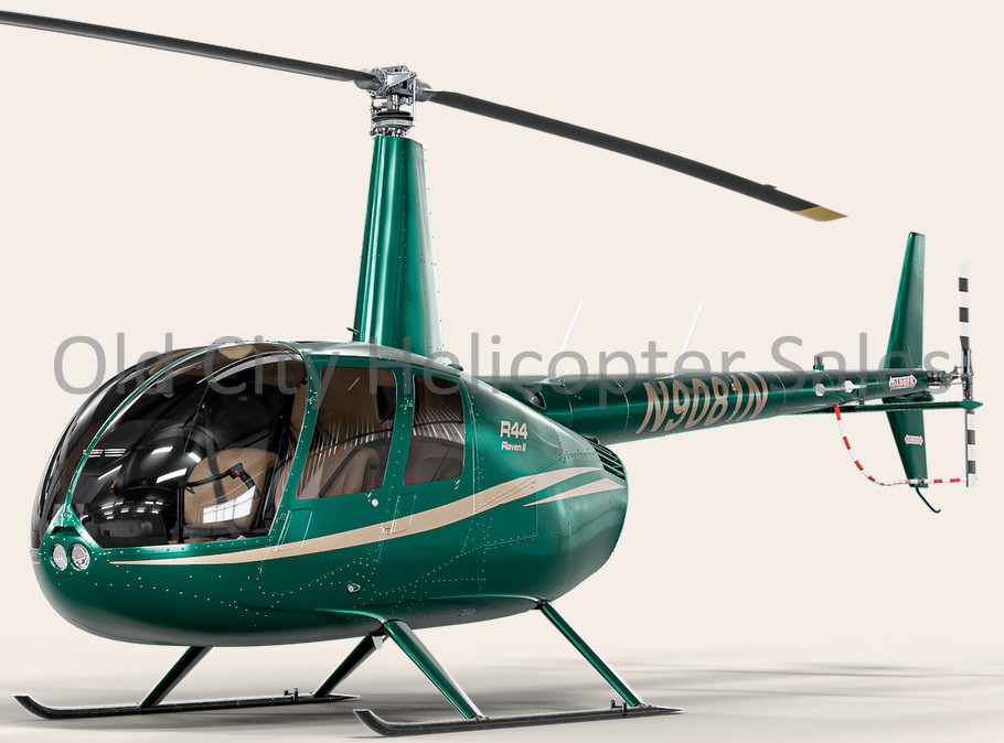
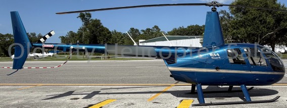
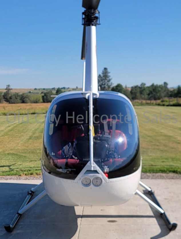
Free — save the R44 Raven II to your watchlist and track it in one place.
More Robinson R44 Raven IImanuals & documents
See all 45 →- U.S. AIRWORTHINESS DIRECTIVESAirworthiness Directives
- Emergency Checklist R44 RII – Heli Academy V1.0 2025-09Checklist
- R44 SERVICE BULLETIN SB-117Service Bulletins
- ROBINSON MAINTENANCE MANUAL R44 SERIESWiring Diagram
- V-Speeds Reference for the Robinson R44 Raven IIV Speeds Reference
- Advisory Circular: Certification: Pilots and Flight and Ground InstructorsTraining Manual
- ROBINSON MODEL R44 SECTION 5 PERFORMANCEPerformance Data
- Airworthiness Directives; Robinson Helicopter Company HelicoptersAirworthiness Directives
- Collision with terrain involving Robinson R44, VH-OCLOther Documents
- MANDATORY SERVICE BULLETIN - LycomingService Bulletins
- PILOT'S OPERATING HANDBOOK AND FAA APPROVED ROTORCRAFT FLIGHT MANUALPilot's Operating Handbook
- Clutch actuator lower bearing seizure and collision with terrain involving Robinson Helicopter Company R44, VH-KOV near Nathan River Station, Northern Territory on 16 May 2022Other Documents
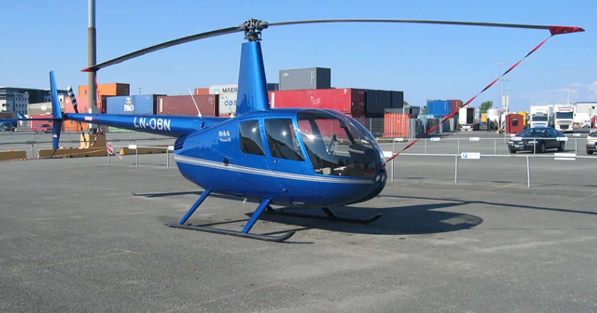
If you fly the Robinson R44 Raven II, you may also be researching these.

In this document
Introduction
The introduction outlines the purpose of the advisory circular, emphasizing the importance of safe heliport design in promoting air commerce and safety. It highlights the FAA's role in regulating heliport operations and the need for compliance with the recommended standards.
Heliport Design
This section provides detailed guidelines for the design of heliports, including site selection, safety area dimensions, and the relationship between touchdown and liftoff areas (TLOF) and final approach and takeoff areas (FATO). It emphasizes the importance of adhering to minimum dimension standards to ensure safe operations.
Heliport Taxiways and Parking
Guidelines for the design of heliport taxiways, taxi routes, and helicopter parking areas are discussed. This section includes specifications for taxiway widths, surfaces, and gradients, as well as recommendations for parking position sizes and fueling areas.
Heliport Markings and Lighting
Standards for heliport markings and lighting are outlined, including the requirements for retroreflective markers, identification markings, and lighting for TLOF and FATO areas. This section ensures that heliports are clearly marked for safe navigation.
Instrument Operations
This section covers the planning and design considerations for instrument operations at heliports, including airspace requirements and the installation of instrument lighting systems to facilitate safe landings and takeoffs in low visibility conditions.
Full document text
U.S. Department of Transportation Federal Aviation Administration Advisory Circular Subject: Heliport Design Date: 1/5/2023 Initiated By: AAS-100 AC No: 150/5390-2D Change: 1 Purpose. This advisory circular (AC) provides standards for the planning, design and construction of heliports serving helicopters with single, tandem (front and rear) or dual (side by side) rotors. 2 Cancellation. This AC cancels AC 150/5390-2C, Heliport Design, dated April 24, 2012. 3 Applicability. The Federal Aviation Administration (FAA) recommends the standards and guidelines in this AC for uniformity in planning, design, and construction of heliports. This AC does not constitute a regulation, is not mandatory and is not legally binding in its own right. This AC will not be relied upon as a separate basis by the FAA for affirmative enforcement action or other administrative penalty. The standards and guidelines contained in this AC are practices the FAA recommends for establishing an acceptable level of safety, performance, and operation for heliports. Conformity with this AC is voluntary, except for the projects described in subparagraphs 1, 2, and 3 below: Use of these standards and guidelines is mandatory for projects funded under Federal grant assistance programs, including but not limited to the Airport Improvement Program (AIP) and Coronavirus Aid, Relief, and Economic Security (CARES) Act Airport Grants program. See Grant Assurance #34. Heliport sponsors should familiarize themselves with the obligations and assurances that apply to each grant program from which they obtained grant funds. This AC is mandatory, as required by regulation, for projects funded by the Passenger Facility Charge (PFC) program. See PFC Assurance #9. This AC has no applicability under Title 14 Code of the Federal Regulations (CFR) Part 139 due to an exemption for heliport operators per § 139.1(c)(5). Other federal agencies, states, or other authorities having jurisdiction over the construction of heliports not funded with AIP, CARES Act, or PFC funds have discretion in establishing the extent to which these standards apply. 1/5/2023 AC 150/5390-2D ii 4 Related Documents. ACs and Orders referenced in the text of this AC do not include a revision letter, as they refer to the latest version. See Appendix E for a list of associated publications. 5 Principal Changes. The AC incorporates the following principal changes: Complete reorganization of this AC: a. Consolidated Chapters 2, 3 and 4 (GENERAL AVIATION, TRANSPORT, and HOSPITAL heliport chapters, respectively) into Chapter 2. b. Consolidated Chapter 7 (Heliport Gradients and Pavement Design) into Chapter 2. c. Included a separate Chapter 3 on Heliport Taxiways, Taxi Routes, and Helicopter Parking. d. Included a separate Chapter 4 on Heliport Markings and Lighting. e. Included a separate Chapter 7 on Heliport Site Safety Elements. f. Added new Appendix B, Pre-designated Emergency Landing Areas (PELAs). g. Incorporated Engineering Brief #87, Heliport Perimeter Light for Visual Meteorological Conditions, into this AC to address specific heliport lighting requirements. Heliport lighting design requirements are included in Appendix G. Revised figures and tables to correspond with the design requirements and dimensions for GENERAL AVIATION, TRANSPORT, and HOSPITAL heliports. Enhanced the figures to include dimensional, layout, and offset requirements. Updated the format of the document and made minor editorial changes throughout. Included a heliport evaluation process flow chart in Appendix F. 6 Using this Document. Hyperlinks (allowing the reader to access documents located on the internet and to maneuver within this document) are provided throughout this document and are identified with underlined text. When navigating within this document, return to the previously viewed page by pressing the “ALT” and “ ←” keys simultaneously. Figures in this document are general representations and are not to scale. Colors and shading used in the figures are illustrative only. Guidance on specific heliport markings is provided in Chapter 4. 7 Use of Metrics. Throughout this AC, U.S. customary units are used followed with “soft” (rounded) conversion to metric units. The U.S. customary units govern. 1/5/2023 AC 150/5390-2D iii 8 Where to Find this AC. You can view a list of all ACs at https://www.faa.gov/regulations_policies/advisory_circulars/. You can view the Federal Aviation Regulations at https://www.faa.gov/regulations_policies/faa_regulations/. 9 Feedback on this AC. If you have suggestions for improving this AC, you may use the Advisory Circular Feedback form at the end of this AC. John R. Dermody Director of Airport Safety and Standards 1/5/2023 AC 150/5390-2D CONTENTS Paragraph Page iv CHAPTER 1. Introduction ....................................................................................................... 1-1 1.1 Background. .................................................................................................................. 1-1 1.2 General. ......................................................................................................................... 1-1 1.3 Facilities. ....................................................................................................................... 1-1 1.4 Planning. ....................................................................................................................... 1-2 1.5 Existing Heliports. ........................................................................................................ 1-2 1.6 Location. ....................................................................................................................... 1-2 1.7 AC Organization. .......................................................................................................... 1-3
Show full textShow less
1.8 Explanation of Terms.................................................................................................... 1-3 1.9 Selection of Approach/Departure Paths. ..................................................................... 1-10 1.10 Notification Requirements. ......................................................................................... 1-10 1.11 Hazards to Air Navigation. ......................................................................................... 1-15 1.12 Federal Assistance. ..................................................................................................... 1-18 1.13 Environmental Impact Analyses. ................................................................................ 1-18 1.14 Terminal Facilities Design Considerations. ................................................................ 1-19 1.15 Zoning for Compatible Land Use. .............................................................................. 1-19 1.16 Access to Heliports by Individuals with Disabilities. ................................................. 1-20 1.17 State Role. ................................................................................................................... 1-20 1.18 Local Role and Building Code.................................................................................... 1-20 1.19 Related Referenced Material....................................................................................... 1-20 CHAPTER 2. Heliport Design .................................................................................................. 2-1 2.1 General. ......................................................................................................................... 2-1 2.2 Prior Permission Required (PPR) Facilities.................................................................. 2-1 2.3 Design Approach. ......................................................................................................... 2-1 2.4 Access by Individuals with Disabilities. ....................................................................... 2-1 2.5 Heliport Site Selection. ................................................................................................. 2-4 2.6 TLOF/FATO and Safety Area Relationships. .............................................................. 2-7 2.7 Touchdown and Liftoff Area (TLOF)........................................................................... 2-9 2.8 Final Approach and Takeoff Area (FATO). ............................................................... 2-17 1/5/2023 AC 150/5390-2D CONTENTS Paragraph Page v 2.9 Safety Area.................................................................................................................. 2-21 2.10 Fall Protection and Safety Net Design. ....................................................................... 2-24 2.11 Pavement Design and Soil Stabilization. .................................................................... 2-25 2.12 VFR Approach/Departure Paths. ................................................................................ 2-27 2.13 Heliport Protection Zone (HPZ). ................................................................................ 2-35 2.14 Wind Cone. ................................................................................................................. 2-35 CHAPTER 3. Heliport Taxiways, Taxi Routes, and Helicopter Parking ............................ 3-1 3.1 General. ......................................................................................................................... 3-1 3.2 Taxiways and Taxi Routes. ........................................................................................... 3-1 3.3 Taxiway/Taxi Route Widths. ........................................................................................ 3-1 3.4 Taxiway Surfaces. ......................................................................................................... 3-6 3.5 Taxiway and Taxi Route Gradients. ............................................................................. 3-6 3.6 Helicopter Parking. ....................................................................................................... 3-6 3.7 Parking Position Sizes................................................................................................. 3-13 3.8 Walkways.................................................................................................................... 3-16 3.9 Fueling. ....................................................................................................................... 3-16 3.10 Tiedowns. .................................................................................................................... 3-16 CHAPTER 4. Heliport Markings and Lighting...................................................................... 4-1 4.1 General. ......................................................................................................................... 4-1 4.2 Heliport Retroreflective Markers and Markings. .......................................................... 4-1 4.3 Standard Heliport Identification Marking. .................................................................... 4-1 4.4 TLOF and FATO Markings. ......................................................................................... 4-6 4.5 Extended Pavement/Structure Markings for GENERAL AVIATION and HOSPITAL Heliports. ................................................................................................ 4-10 4.6 FATO Perimeter Markings. ........................................................................................ 4-10 4.7 Flight Path Alignment Guidance Marking. ................................................................. 4-11 4.8 Taxiway and Taxi Route Markings............................................................................. 4-12 4.9 Helicopter Parking Position Markings. ....................................................................... 4-13 4.10 Walkways.................................................................................................................... 4-14 4.11 Closed Heliport. .......................................................................................................... 4-14 1/5/2023 AC 150/5390-2D CONTENTS Paragraph Page vi 4.12 Marking Sizes. ............................................................................................................ 4-15 4.13 Heliport Lighting. ....................................................................................................... 4-15 CHAPTER 5. Helicopter Facilities on Airports...................................................................... 5-1 5.1 General. ......................................................................................................................... 5-1 5.2 Touchdown and Liftoff Area (TLOF)........................................................................... 5-1 5.3 On-Airport Location of Final Approach and Takeoff Area (FATO). ........................... 5-1 5.4 Safety Area.................................................................................................................... 5-3 5.5 VFR Approach/Departure Paths. .................................................................................. 5-3 5.6 Heliport Protection Zone (HPZ). .................................................................................. 5-3 5.7 Taxiways and Taxi Routes. ........................................................................................... 5-3 5.8 Helicopter Parking. ....................................................................................................... 5-4 5.9 Security. ........................................................................................................................ 5-4 CHAPTER 6. Instrument Operations ..................................................................................... 6-1 6.1 General. ......................................................................................................................... 6-1 6.2 Planning. ....................................................................................................................... 6-3 6.3 Airspace. ....................................................................................................................... 6-3 6.4 Final Approach Reference Area (FARA). .................................................................... 6-3 6.5 Improved Instrument Lighting System. ........................................................................ 6-4 6.6 Obstacle Evaluation Surfaces. ...................................................................................... 6-8 6.7 Visual Glideslope Indicators (VGSI). ........................................................................... 6-8 CHAPTER 7. Heliport Site Safety Elements .......................................................................... 7-1 7.1 General. ......................................................................................................................... 7-1 7.2 Marking and Lighting of Difficult-To-See Objects. ..................................................... 7-1 7.3 Safety Considerations. .................................................................................................. 7-4 Appendix A. Emergency Helicopter Landing Facilities (EHLF)........................................ A-1 A.1 General. ........................................................................................................................ A-1 A.2 Notification and Coordination. .................................................................................... A-1 A.3 Rooftop Emergency Facilities...................................................................................... A-1 1/5/2023 AC 150/5390-2D CONTENTS Paragraph Page vii Appendix B. Pre-designated Emergency Landing Areas (PELAs) .....................................B-1 Appendix C. Helicopter Data ................................................................................................. C-1 Appendix D. Dimensions for Marking Size and Weight Limitations................................. D-1 Appendix E. Associated Publications and Resources ...........................................................E-1 Appendix F. Heliport Evaluation Process Flow Chart ......................................................... F-1 Appendix G. Design Requirements for Heliport Perimeter Lighting ................................ G-1 G.1 Elevated and In-pavement Omnidirectional Helipad Perimeter Light. ....................... G-1 G.2 Photometric Requirements. .......................................................................................... G-2 G.3 Additional Heliport Perimeter Light Requirements. .................................................... G-2 G.4 L-860H and L-852H Light Fixture Testing. ................................................................ G-3 G.5 Installation Criteria. ..................................................................................................... G-3 1/5/2023 AC 150/5390-2D viii FIGURES Figure 1-1. FAA Form 7480-1, Notice for Construction, Alteration and Deactivation of Airports .................................................................................................................................. 1-12 Figure 1-2. Example of a Heliport Layout Plan......................................................................... 1-13 Figure 1-3. Example of a Heliport Location Map...................................................................... 1-14 Figure 1-4. Offsite Development Requiring Notice to the FAA ............................................... 1-17 Figure 2-1. GENERAL AVIATION Heliport – Basic Features .................................................. 2-2 Figure 2-2. TRANSPORT Heliport – Basic Features.................................................................. 2-3 Figure 2-3. HOSPITAL Heliport (Ground Level) – Basic Features............................................ 2-4 Figure 2-4. Heliport EMI Hazard Marking .................................................................................. 2-6 Figure 2-5. Heliport EMI Hazard Sign ........................................................................................ 2-7 Figure 2-6. TLOF/FATO/Safety Area Relationships and Minimum Dimensions ...................... 2-8 Figure 2-7. Heliport Gradients and Rapid Runoff Shoulder - Load-bearing FATOs ................ 2-12 Figure 2-8. Optional Elongated TLOF and FATO with Two Takeoff Positions....................... 2-13 Figure 2-9. Elevated Heliport: GENERAL AVIATION and HOSPITAL ................................ 2-15 Figure 2-10. Elevated Heliport: TRANSPORT ......................................................................... 2-16 Figure 2-11. Additional FATO Length for Heliports at Higher Elevations .............................. 2-19 Figure 2-12. Non-load-bearing FATO and Safety Area over Water: GENERAL AVIATION and HOSPITAL Heliports .............................................................................................. 2-23 Figure 2-13. Non-load-bearing Safety Area over Water: TRANSPORT .................................. 2-24 Figure 2-14. Helicopter Landing Gear Loading: Gradients and Pavement ............................... 2-26 Figure 2-15. VFR Heliport Approach/Departure and Transitional Surfaces ............................. 2-28 Figure 2-16. VFR Curved Approach/Departure and Transitional Surfaces – GENERAL AVIATION and TRANSPORT Heliports ............................................................... 2-29 Figure 2-17. VFR HOSPTIAL and PPR Heliport Optional Lateral Extensions of the 8:1 Approach/Departure Surface ................................................................................... 2-31 Figure 2-18. VFR HOSPITAL and PPR Heliport Optional Lateral Extension of the Curved 8:1 Approach/Departure Surface ................................................................................... 2-33 Figure 2-19. Flight Path Alignment Marking and Lights .......................................................... 2-34 Figure 2-20. Heliport Protection Zone (HPZ)............................................................................ 2-36 Figure 3-1. Taxiway/Taxi Route Relationship – Paved Taxiway ................................................ 3-2 1/5/2023 AC 150/5390-2D ix Figure 3-2. Taxiway/Taxi Route Relationship – Unpaved Taxiway with Elevated Retroreflective Edge Markers ............................................................................................................. 3-3 Figure 3-3. Taxiway/Taxi Route Relationship – Unpaved Taxiway with In-Pavement Retroreflective Edge Markers .................................................................................... 3-4 Figure 3-4. Hover Taxi Area ........................................................................................................ 3-5 Figure 3-5. Typical Parking Area Design – “Taxi-through” Parking Positions. ......................... 3-7 Figure 3-6. Typical Parking Area Design – “Turn-around” Parking Positions ........................... 3-8 Figure 3-7. Typical Parking Area Design – “Back-out” Parking Positions................................. 3-9 Figure 3-8. “Turn-around” Parking Position Marking............................................................... 3-11 Figure 3-9. “Taxi-through” and “Back-out” Parking Position Marking .................................... 3-12 Figure 3-10. Parking Position Identification, Size, and Weight Limitations – Paved Areas, Turn- Around Parking ........................................................................................................ 3-14 Figure 3-11. Parking Position Identification, Size, and Weight Limitations – Paved Areas, “Taxi- through” and “Back-out” Parking ............................................................................ 3-15 Figure 4-1. Standard TLOF Markings ......................................................................................... 4-3 Figure 4-2. Standard Heliport Identification Symbol, TLOF Size and Weight Limitations ....... 4-4 Figure 4-3. HOSPITAL Heliport – Standard Identification Marking.......................................... 4-5 Figure 4-4. HOSPITAL Heliport – Alternative Identification Marking ...................................... 4-6 Figure 4-5. Paved TLOF/Paved FATO – Paved TLOF/Unpaved FATO – Marking: TRANSPORT Heliports and Other Heliports with a Paved TLOF ........................... 4-7 Figure 4-6. Unpaved TLOF/Unpaved FATO – Marking: GENERAL AVIATION and HOSPITAL Heliports ................................................................................................ 4-8 Figure 4-7. Extended Pavement/Structure Marking: GENERAL AVIATION and HOSPITAL Heliports................................................................................................................... 4-11 Figure 4-8. Marking a Closed Heliport ...................................................................................... 4-15 Figure 4-9. Elevated TLOF – Perimeter Lighting ..................................................................... 4-17 Figure 4-10. TLOF/FATO Perimeter Lighting .......................................................................... 4-18 Figure 4-11. TLOF In-pavement and FATO Elevated Perimeter Lighting ............................... 4-19 Figure 4-12. FATO Elevation .................................................................................................... 4-21 Figure 4-13. Landing Direction Lights. ..................................................................................... 4-23 Figure 5-1. Example of Heliport Facilities Located on an Airport .............................................. 5-2 Figure 6-1. FARA/FATO Relationship: Precision Instrument Procedure ................................... 6-4 Figure 6-2. Heliport Instrument Lighting System (HILS): Non-precision .................................. 6-6 Figure 6-3. Heliport Approach Lighting System ......................................................................... 6-7 Figure 6-4. Visual Glideslope Indicator (VGSI) Siting and Clearance Criteria .......................... 6-9 1/5/2023 AC 150/5390-2D x Figure 7-1. Airspace Where Heliport Marking and Lighting are Recommended: Straight Approach .................................................................................................................... 7-2 Figure 7-2. Airspace Where Heliport Marking and Lighting are Recommended: Curved Approach .................................................................................................................... 7-3 Figure 7-3. Heliport Caution Sign ............................................................................................... 7-5 Figure A-1. Rooftop Emergency Landing Facility ..................................................................... A-2 Figure C-1. Helicopter Dimensions ............................................................................................ C-2 Figure D-1. Form and Proportions of 36-inch (0.9 m) Numbers for Marking Size and Weight Limitations ................................................................................................................ D-2 Figure D-2. Form and Proportions of 18-inch (0.5 m) Numbers for Marking Size and Weight Limitation.................................................................................................................. D-3 Figure G-1. Perimeter Light Intensity Distribution .................................................................... G-2 TABLES Table 2-1. TLOF/FATO Minimum Dimensions 1 ...................................................................... 2-8 Table 2-2. Minimum Dimensions for Elongated FATO with Two Takeoff Positions .............. 2-13 Table 2-3. TLOF Elevation and Configuration of Rooftop and other Elevated Heliports ........ 2-14 Table 2-4. Minimum VFR Safety Area Width as a Function of Heliport Markings GENERAL AVIATION, HOSPITAL, and PPR Heliports ......................................................... 2-21 Table 2-5. Differences in Safety Net Design for Rooftop and Elevated Heliports.................... 2-25 Table 3-1. Taxiway/Taxi Route Dimensions – GENERAL AVIATION, TRANSPORT, and HOSPITAL Heliports ................................................................................................ 3-5 Table 4-1. FATO Perimeter Light Design ................................................................................. 4-20 Table 5-1. Recommended Distance between FATO Center to Runway Centerline for VFR Operations .................................................................................................................. 5-3 Table 6-1. Standards for Instrument Approach Procedures ......................................................... 6-2 Table C-1. Helicopter Data ......................................................................................................... C-3 Table G-1. Helicopter Approach Angles Assuming VMC ......................................................... G-1 Table G-2. Perimeter Lighting Intensity Recommendations ...................................................... G-2 1/5/2023 AC 150/5390-2D 1-1 CHAPTER 1. Introduction 1.1 Background. Section 103 of the Federal Aviation Act of 1958 states in part, “In the exercise and performance of his power and duties under this Act, the Secretary of Transportation shall consider the following, among other things, as being in the public interest: (a) The regulation of air commerce in such manner as to best promote its development and safety and fulfill the requirements of defense; (b) The promotion, encouragement, and development of civil aeronautics . . .” This public charge, in effect, requires the development and maintenance of a national system of safe heliports. Using the standards and recommendations contained in this publication in the design of heliports supports this public charge. These standards and recommendations do not limit or regulate the operations of helicopters, aircraft or heliports. When it is not feasible to meet the standards and recommendations in this advisory circular (AC), consult with the appropriate offices of the Federal Aviation Administration (FAA) Office of Airports and Flight Standards Service to identify possible adjustments to include operational procedures that accommodate safe heliport operations to the maximum extent. The guidance provided in this AC is limited to heliports and helicopter operations. This AC does not specifically consider the characteristics of all vertical takeoff and landing (VTOL) aircraft or unmanned aircraft. New aircraft entrants that have an interest in operating at heliports should work with the FAA Office of Airports and Flight Standards to demonstrate that their aircraft’s operational and safety parameters comply with this AC, prior to operations. The FAA is developing guidance for vertiports that would be intended for VTOL and/or unmanned aircraft. Until that guidance is published, entities developing operating sites for new aircraft entrants are encouraged to work with the FAA Office of Airports and Flight Standards on applicable design, operational, and safety criteria tailored to the performance of aircraft which intend to operate at those facilities. 1.2 General. This chapter provides: • an explanation of terms used in this AC, • notification responsibilities of heliport proponents to the FAA, • general heliport siting guidance, and • sources of technical information relating to the planning and design of a civil heliport. 1.3 Facilities. Most heliports are not large and elaborate. A minimal facility may be adequate as a private-use prior permission required (PPR) heliport (see Appendix A) and may serve as the initial phase in the development of a public-use heliport capable of serving the 1/5/2023 AC 150/5390-2D 1-2 general aviation segment of the helicopter community. See Chapter 2 for requirements and design guidance for each specific heliport type. The basic elements of a heliport include: • clear approach/departure paths, • clear area for ground maneuvers, • final approach and takeoff area (FATO), • touchdown and liftoff area (TLOF), • safety area, and • a wind cone. 1.4 Planning. This AC is a design document intended to assist engineers, architects, and city planners to design, locate, and build a suitable heliport. While the heliport itself may be simple, the planning and organization necessary to properly develop a heliport can present challenges. Ensure proper consideration of the physical, technical, safety, and public interest matters described in this document during the planning and establishment of a heliport. 1.5 Existing Heliports. Whenever a change or alteration to an existing heliport requires the submission of FAA Form 7460-1, Notice of Proposed Construction or Alteration, or FAA Form 7480-1, Notice of Landing Area Proposal, consider taking necessary actions, as practical, to bring the heliport up to current design standards. Refer to paragraph 1.11.3 for additional information. 1.6 Location. The optimum location for a heliport is near the desired origination and/or destination of the potential heliport users. Industrial, commercial, and medical operations in urban locations are demand generators for helicopter services, even though they often compete for the limited ground space available. 1.6.1 Factors to Consider. Heliport sites adjacent to a river, lake, railroad, freeway, or highway offer potential for multi-functional land usage. Locations that have the advantage of unobstructed airspace and which have properly enacted zoning can provide further protection from disruptive encroachment. Requirements for scheduled “airline-type” passenger services may necessitate the development of an instrument procedure to permit “all-weather” service. 1/5/2023 AC 150/5390-2D 1-3 1.7 AC Organization. This AC covers GENERAL AVIATION heliports (including PPR heliports), TRANSPORT heliports, HOSPITAL heliports, and emergency landing facilities. Heliport proponent familiarity with the terminology used in this specialized field is imperative. See paragraph 1.8 for specific heliport terminology and definitions. 1.7.1 Helicopter Facilities on Airports. Consider developing separate heliport facilities for helicopter use when there are a significant number of helicopter operations on an airport. Chapter 5 addresses helicopter facilities on airports. 1.7.2 Instrument Operations. Instrument approach procedures at heliports are practical since the introduction of the global positioning system (GPS). Good planning suggests that heliport proponents plan for the eventual development of instrument approaches to their heliports. Consider the recommendations in Chapter 6 in contemplating future instrument operations at a heliport during heliport site selection and design, even if the heliport will not initially have instrument operations. 1.7.3 Heliport Gradients and Pavement Design. Chapter 2 provides guidance on heliport gradients and pavement design issues. 1.7.4 Additional Information and Resources. Additional information and resources are found in the Appendices as follows: • Appendix A provides guidance on emergency helicopter landing facilities. • Appendix B provides guidance for pre-designated emergency landing areas. • Appendix C provides helicopter dimensional data. • Appendix D provides guidance on the form, size, and proportions of certain heliport markings. • Appendix E provides a list of associated publications and resources referenced in this AC. • Appendix F provides a heliport evaluation process flow chart. • Appendix G provides design guidance on heliport lighting. 1.8 Explanation of Terms. The Pilot/Controller Glossary of the Aeronautical Information Manual (AIM) defines terms used in the Air Traffic System. Copies of the AIM are available from the FAA website https://www.faa.gov/air_traffic/publications/. Other terms used in this publication follow. 1.8.1 Air Taxi. Refers to helicopter taxi operations, typically below 100 feet (30.5 m) above ground level (AGL), which allows helicopter movement from one point to another. 1/5/2023 AC 150/5390-2D 1-4 1.8.2 Approach/Departure Path. The flight track helicopters follow when landing at or departing from a heliport. The approach/departure paths may be straight or curved. 1.8.3 Controlling Dimension (D). The greater of helicopter overall length (OL) and overall width (OW). 1.8.4 Design Helicopter. A single or composite helicopter that reflects the maximum weight, maximum contact load/minimum contact area, controlling dimension (D), overall width (OW), rotor diameter (RD), tail rotor arc radius, undercarriage dimensions, and pilot’s eye height of all helicopters expected to operate at the heliport. 1.8.5 Design Loads. Design and construct the touchdown and lift area (TLOF), and any load-bearing surfaces, to support the loads imposed by the design helicopter and any ground support vehicles and equipment. 1.8.5.1 Static Load. For design purposes, the design static load is equal to the helicopter’s maximum takeoff weight applied through the total contact area of the wheels or skids. See paragraph 2.7.3.1. 1.8.5.2 Dynamic Load. For design purposes, assume the dynamic load at 150 percent of the maximum takeoff weight of the design helicopter applied through the main undercarriage on a wheel-equipped helicopter or aft contact areas of skid- equipped helicopter. See paragraph 2.7.3.2. 1.8.6 Elevated Heliport. A heliport located on a rooftop or other elevated structure where the TLOF is at least 30 inches (0.8 m) above the surrounding surface (a ground-level heliport with the TLOF on a mound is not an elevated heliport). 1.8.7 Emergency Helicopter Landing Facility (EHLF). A clear area at ground level or on the roof of a building capable of accommodating helicopters engaged in fire fighting and/or emergency evacuation operations. An EHLF meets the definition of a heliport in this AC and under 14 CFR Part 157, Notice of Construction, Alteration, Activation, and Deactivation of Airports. 1.8.8 Final Approach and Takeoff Area (FATO). A defined area over which the pilot completes the final phase of the approach to a hover or a landing and from which the pilot initiates takeoff. The FATO and TLOF are normally co-located but may be located separately. The FATO is associated with all instrument approach/departure procedures. 1/5/2023 AC 150/5390-2D 1-5 1.8.9 Final Approach Reference Area (FARA). An obstacle-free area with its center aligned on the final approach course. It is located at the end of a precision instrument FATO. 1.8.10 Frangibly Mounted. While there is no accepted standard for frangibility regarding helicopter operations, remove all objects from a FATO and safety area except those of the lowest mass practicable and frangibly mounted objects no higher than 2 inches (51 mm) above the adjacent TLOF elevation, to the extent practicable. 1.8.11 GENERAL AVIATION (GA) Heliport. A heliport intended to accommodate individuals, corporations, aerial tourism, and public safety agencies. For the purposes of this AC, “general aviation” refers to all helicopter operations other than scheduled service (with the exception of unscheduled service with helicopters with maximum takeoff weight (MTOW) greater than 12,500 pounds (lbs)). HOSPITAL heliports and emergency landing facilities fall under general aviation but are treated separately in the AC due to their specific requirements. GENERAL AVIATION heliports may be publicly or privately owned. 1.8.12 Ground Taxi. The surface movement of a wheeled helicopter under its own power with wheels touching the ground. 1.8.13 Hazard to Air Navigation. An existing or proposed object that the FAA, as a result of an aeronautical study, determines will have a substantial adverse effect upon the safe and efficient use of navigable airspace by helicopters and other aircraft, operation of air navigation facilities, or existing or potential airport capacity. 1.8.14 Helipad. A small, designated area, usually with a prepared surface, on a heliport, airport, landing/takeoff area, apron/ramp, or movement area used for takeoff, landing, or parking of helicopters. A helipad on an airport does not constitute a heliport. 1.8.15 Heliport. An area of land, water, or structure used or intended to be used for helicopter landings and takeoffs and includes associated buildings and facilities. 1.8.16 Heliport Elevation. The highest elevation of all helicopter landing areas (TLOFs) within the heliport, expressed as the distance above mean sea level (MSL). 1.8.17 Heliport Imaginary Surfaces. The imaginary planes defined in 14 CFR Part 77, Safe, Efficient Use, and Preservation of the Navigable Airspace, centered about the FATO and the approach/departure paths, which are used to identify the objects where notice to and evaluation by the FAA is 1/5/2023 AC 150/5390-2D 1-6 required. Recommendations for mitigating possible obstructions to air navigation may include realignment of approach/departure paths or removal, lowering, marking, and lighting of objects. 1.8.18 Heliport Layout Plan. The plan of a heliport showing the layout of existing and proposed heliport facilities including the approach/departure paths and dimensions of TLOF, FATO, and Safety Area. 1.8.19 Heliport Protection Zone (HPZ). An area off the end of the FATO and under the approach/departure path intended to enhance the protection of people and property on the ground. 1.8.20 Heliport Reference Point (HRP). The geographic position of the heliport expressed as the latitude and longitude at: The center of the FATO, or the centroid of multiple FATOs, for heliports having visual and non-precision instrument approach procedures; or The center of the final approach reference area (FARA) when the heliport has a precision instrument procedure. 1.8.21 Helistop. A heliport that provides no fueling, defueling, maintenance, repairs, or storage of helicopters. The geometry and approach/departure surfaces of a helistop are identical to those of a heliport. This AC does not use this term, as the design standards and recommendations in this AC apply to all heliports. 1.8.22 HOSPITAL Heliport. A HOSPITAL heliport services helicopters used by helicopter air ambulance providers. A HOSPITAL heliport may be designed to accommodate large military helicopters in some emergencies. Air ambulance helicopters are often used to transport injured persons from the scene of an accident to a hospital and to transfer patients from one hospital to another. A designated helicopter landing area located at a hospital or medical facility is a heliport and not a medical emergency site. 1.8.23 Hover Taxi. The movement of a helicopter above the surface, typically used to move short distances from one point to another. Generally, this takes place at a wheel/skid height of 1 to 5 feet (0.3 to 1.5 m) and at a slow ground speed of less than 20 knots (37 kilometers(km)/h). For facility design purposes, assume a skid-equipped helicopter to hover-taxi. 1.8.24 In-Pavement Lights. Where the term “in-pavement lights” is specified in this AC, interpret it as including in- ground lights. 1/5/2023 AC 150/5390-2D 1-7 1.8.25 Landing Position. An area, normally located in the center of an elongated TLOF, on which the helicopter lands. 1.8.26 Large Helicopter. A helicopter with a maximum takeoff weight of more than 12,500 lbs (5,670 kilograms (kg)). 1.8.27 Load-Bearing Area (LBA). The portion of the TLOF and any additional support structure capable of supporting the dynamic load of the design helicopter. 1.8.28 Medical Emergency Site. An unprepared site at or near the scene of an accident or similar medical emergency on which a helicopter may land to pick up a patient to provide emergency medical transport. A medical emergency site is not a heliport as defined in this AC. 1.8.29 Medium Helicopter. A helicopter with a maximum takeoff weight of more than 7,000 lbs (3,175 kg) and up to 12,500 lbs (5,670 kg). 1.8.30 Obstruction to Air Navigation. Any fixed or mobile object, including a parked helicopter, of greater height than any of the heights or surfaces presented in subpart C of Part 77. 1.8.31 Overall Helicopter Length (OL). The overall length of the helicopter, which is the dimension from the tip of the main or forward rotor to the tip of the tail rotor, fin, or other rear-most point of the helicopter. This value is with the rotors at their maximum extension. See Appendix C. If only the value of the RD is known, estimate the value for OL using the relationship OL = 1.2 RD (or conversely, RD = 0.83 OL). 1.8.32 Overall Width (OW). The OW is defined as the maximum outer dimension of the aircraft rotors or wings. See Appendix C. 1.8.33 Parking Pad. The center portion of a helicopter parking position, whether paved or grass. 1.8.34 Prior Permission Required (PPR) Heliport. A heliport developed for exclusive use of the owner and persons authorized by the owner and about which the owner and operator ensure all authorized pilots are thoroughly knowledgeable. These features include but are not limited to: • approach/departure path characteristics • preferred heading 1/5/2023 AC 150/5390-2D 1-8 • lighting • obstacles in the area • size and weight capacity of the facility • heliport facility limitations 1.8.35 Public-use Heliport. A heliport available for use by the public without a requirement for prior approval of the owner or operator. 1.8.36 Rotor Diameter (RD). The length of the main rotor, from tip to tip. 1.8.37 Rotor Downwash. The downward movement of air caused by the action of the rotating main rotor blades. When this air strikes the ground or some other surface, it causes a turbulent outflow of air from beneath the helicopter. 1.8.38 Safety Area. A defined area on a heliport surrounding the FATO intended to reduce the risk of damage to helicopters accidentally diverging from the FATO. 1.8.39 Shielded Obstruction. A proposed or existing obstruction that does not need to be marked or lighted due to its proximity to another obstruction whose highest point is at the same or higher elevation. 1.8.40 Shoulder Line. A marking line perpendicular to a helicopter parking position centerline that is intended to provide the pilot with a visual cue to assist in parking. 1.8.41 Small Helicopter. A helicopter with a maximum takeoff weight of 7,000 lbs (3,175 kg) or less. 1.8.42 Tail Rotor Arc Radius. The distance from the hub of the main rotor to the outermost tip of the tail rotor or the rear-most point of the helicopter tail, whichever is farther. 1.8.43 Takeoff Position. An area, normally located on the centerline and at the ends of an elongated TLOF, from which the helicopter takes off. Typically, there are two such positions on an elongated TLOF, one at each end. 1.8.44 Taxi Route. An obstruction-free corridor established for the movement of helicopters from one part of a heliport/airport to another. A taxi route includes the taxiway plus the appropriate clearances on both sides. 1/5/2023 AC 150/5390-2D 1-9 1.8.45 Taxiway. A marked route between the TLOF and other areas on the heliport. This AC defines two types of helicopter taxiways: 1.8.45.1 Ground Taxiway. A taxiway intended to permit the surface movement of a wheeled helicopter under its own power with wheels on the ground. The minimum dimensions defined for a ground taxiway may not be adequate for hover taxi. 1.8.45.2 Hover Taxiway. A taxiway intended to permit the hover taxiing of a helicopter. 1.8.46 Touchdown and Liftoff Area (TLOF). A load-bearing (generally paved) area normally centered in the FATO, on which the helicopter performs a touchdown or liftoff. 1.8.47 Transitional Surface. An imaginary surface which, in conjunction with the approach/departure surface, provides airspace clear of hazards to allow safe approaches to, and departures from, the FATO. 1.8.48 TRANSPORT Heliport. A heliport designed to accommodate air carriers providing scheduled service on large helicopters (helicopters with a maximum takeoff weight greater than 12,500 lbs (5,670 kg)). Extensive airside and landside infrastructure is provided to accommodate passengers and to enable operations in instrument meteorological conditions. 1.8.49 Touchdown/Positioning Circle (TDPC) Marking. A circular marking located in the center of a TLOF or a parking position. When the pilot’s seat is over the TDPC, the whole of the helicopter undercarriage will be within the TLOF or parking position, and all parts of the helicopter rotor system, will be clear of any obstacle by a safe margin. 1.8.50 Undercarriage Width (UCW). The distance between the outside edges of the outer tires or skids. See Figure B-1. 1.8.51 Unshielded Obstruction. A proposed or existing obstruction that may need to be marked or lighted since it is not near another marked and lighted obstruction whose highest point is at the same or higher elevation. 1/5/2023 AC 150/5390-2D 1-10 1.9 Selection of Approach/Departure Paths. Design heliports to the extent practicable for two approach/departure paths. Consider wind, obstructions, and environmental impacts, for example, in selecting the approach/departure paths. 1.9.1 Wind. Well-designed approach/departure paths permit pilots to avoid downwind conditions and minimize crosswind operations. Align the preferred flight approach paths and departure paths, to the extent feasible, with the predominant wind direction. Base other approach paths and departure paths on the assessment of the prevailing winds or, when this information is not available, separate such flight paths and the preferred flight path by at least 135 degrees. If it is not feasible to provide adequate coverage of wind conditions through multiple approach/departure paths, operational limitations may be necessary under certain wind conditions. See paragraph 2.12.1. 1.9.2 Obstructions. In determining approach/departure paths, consider any existing or proposed (future) obstructions near the heliport and those likely to be a hazard to air navigation. See paragraph 1.11. 1.9.3 Environmental Impacts. In environmentally sensitive areas, select the final approach/departure path(s) to minimize any environmental impact, providing it does not decrease flight safety. See paragraph 1.13. 1.10 Notification Requirements. Part 157 sets requirements for persons proposing to construct, activate, deactivate, or alter a heliport to give advance notice of their intent to the FAA. This includes but is not limited to the following changes: • changing the size or number of FATOs; • adding, deleting, or changing an approach or departure route; • change to a heliport status (for example, changing the heliport status) from private to public-use or vice versa. File FAA Form 7480-1 (see Figure 1-1) with the appropriate FAA Airports Regional or District Office at least 90 days before construction, alteration, deactivation, or change in use when notification is required. See the FAA Airports website at https://www.faa.gov/airports/ for contact information. Alterations to an existing heliport requiring notification could include changes to heliport dimensions, approach and departure surfaces, heliport location, and heliport relocation to a different site. Appendix F provides the general heliport evaluation process flow chart to be followed by heliport proponents. 1.10.1 Draw the heliport layout plan to scale showing key dimensions, such as: 1/5/2023 AC 150/5390-2D 1-11 • heliport elevation • TLOF size • FATO size • safety area size • distance from safety area perimeter to property edges • approach/departure paths showing locations of: o buildings o trees o fences o power lines o obstructions (including elevations) o schools o churches o hospitals o residential communities o waste disposal sites o other significant features, as specified on FAA Form 7480-1 and shown in Figure 1-2. 1.10.2 The preferred type of heliport location map using current web-based satellite imagery. Show the location of the heliport site and the approach/departure paths on the map. Point out the heliport site on this map with a red arrow. Indicate the latitude and longitude of the proposed heliport in North American Datum of 1983 (NAD-83) coordinates. See Figure 1-3. 1/5/2023 AC 150/5390-2D 1-12 Figure 1-1. FAA Form 7480-1, Notice for Construction, Alteration and Deactivation of Airports See online FAA Form 7480-1. 1/5/2023 AC 150/5390-2D 1-13 Figure 1-2. Example of a Heliport Layout Plan Draw heliport layout plan to scale with key dimensions and locations, including: a. TLOF and FATO size b. Safety area dimensions c. Distances from the safety area perimeter to property boundaries, buildings, etc. d. Site furnishings (bollards, signs, benches, and other site accessories) See Chapter 2 for guidance on heliport facility sizes and shapes. Heliport property line Approach/departure surfaceTLOF FATO Safety Area Future helicopter parking Auto parking area Earhart Avenue City Property City PropertyOffice 1/5/2023 AC 150/5390-2D 1-14 Figure 1-3. Example of a Heliport Location Map 1.10.3 The FAA Role. The FAA will conduct an aeronautical study of the proposed heliport under § 157.7, FAA Determinations. Part (a) of this section of the regulation states: “The FAA will conduct an aeronautical study of an airport proposal and, after consultations with interested persons, as appropriate, issue a determination to the proponent and advise those concerned of the FAA determination. The FAA will consider matters such as the effects the proposed action would have on existing or contemplated traffic patterns of neighboring airports; the effects the proposed action would have on the existing airspace structure and projected programs of the FAA; and the effects that existing or proposed manmade objects (on file with the FAA) and natural objects within the affected area would have on the airport proposal. While determinations consider the effects of the proposed action on the safe and efficient use of airspace by aircraft and the safety of persons and property on the ground, the determinations are only advisory. Except for an objectionable determination, each determination will contain a determination- void date to facilitate efficient planning of the use of the navigable airspace. A determination does not relieve the proponent of responsibility for compliance with any local law, ordinance or regulation, or state or other federal regulation. Aeronautical studies and determinations will not consider environmental or land use compatibility impacts.” Heliport Approach/Departure Surface Heliport 1/5/2023 AC 150/5390-2D 1-15 1.10.4 Penalty for Failure to Provide Notice. Persons who fail to give notice are subject to civil penalty under Title 49 United States Code 46301, Civil Penalties, of not more than $25,000 (or $1,100 if the person is an individual or small business concern). 1.10.5 Notice Exemptions. Section 157.1, Applicability, exempts sites meeting one of the conditions below from the requirement to submit notice. These exemptions do not negate a notice or formal approval requirement prescribed by state law or local ordinance. For the purposes of applying the Part 157 exemption criteria cited in (2) and (3) below, a landing and associated takeoff is considered one operation. Section 157.1 projects are: [A heliport] subject to conditions of a federal agreement that requires an approved current heliport layout plan to be on file with the FAA, or [A heliport] at which flight operations will be conducted under visual flight rules (VFR) and which is used or intended to be used for a period of less than 30 consecutive days with no more than ten operations per day. The intermittent use of a site that is not an established airport, that is used or intended to be used for less than one year, and at which flight operations will be conducted only under VFR. For this part, “intermittent use of a site” means: a. the site is used or is intended to be used for no more than three days in any one week, and b. no more than ten operations will be conducted in any one day at that site. 1.11 Hazards to Air Navigation. Part 77 establishes requirements for notification to the FAA of objects that may affect navigable airspace. See Figure 1-4 for examples of development requiring notice to the FAA. Part 77 sets standards for determining obstructions to navigable airspace and provides for aeronautical studies of such obstructions to determine their effect on the safe and efficient use of airspace. Part 77 applies only to the following: public heliports and public airports; airports operated by a federal agency or the Department of Defense (DoD); and private airports and heliports with at least one FAA-approved instrument approach procedure. 1.11.1 FAA Studies. 1.11.1.1 Part 77. Part 77 defines objects that are obstructions to surfaces. Presume these objects to be hazards to air navigation unless an FAA study determines otherwise. The FAA conducts aeronautical studies to determine the 1/5/2023 AC 150/5390-2D 1-16 physical and electromagnetic effect on the use of navigable airspace, air navigational facilities, public airports and heliports, and private airports and heliports with at least one FAA-approved instrument approach procedure. The FAA encourages public agencies to enact zoning ordinances to prevent man-made features from becoming hazards to navigation. 1.11.1.2 Part 157. FAA aeronautical studies performed under Part 157 establish standards and notification requirements for anyone proposing to construct, alter, or deactivate a civil or joint-use (civil/military) airport or heliport. This regulation also addresses proposals that alter the status or use of airport or heliport facilities. 1.11.2 Mitigation of Hazards. You may mitigate the adverse effect of an object presumed or determined to be a hazard by: Removing the object. Altering the object, for example, reducing its height. Marking and/or lighting the object, provided an FAA aeronautical study has determined that the object would not be a hazard to air navigation if it were marked and/or lighted. Find guidance on marking and lighting objects in AC 70/7460-1, Obstruction Marking and Lighting. 1.11.3 Notification Requirements. Part 77 requires persons proposing certain construction or alteration to give a 45-day notice to the FAA of their intent. Use FAA Form 7460-1, Notice of Proposed Construction or Alteration, to provide notification. See https://oeaaa.faa.gov/ for more information and to download FAA Form 7460-1. Alterations to an existing heliport requiring notification could include changes to heliport dimensions, approach and departure surfaces, heliport location, and heliport relocation to a different site. 1/5/2023 AC 150/5390-2D 1-17 Figure 1-4. Offsite Development Requiring Notice to the FAA Notice under Part 77 is required for all public-use heliports or private-use heliports with at least one FAA-approved instrument approach procedure. Offsite Development Examples for Figure 1-4: ① Building is less than 200 feet (ft) (61 meters (m)) in height, but top will penetrate the 25:1 surface (notice required by § 77.9). ② Antenna is over 200 ft (61 m) in height (notice is required by § 77.9(a)). ③ Antenna is less than 200 ft (61 m) in height and penetrates the 25:1 surface (notice is required by § 77.9(b)(3)). ④ Construction crane penetrates 25:1 surface (notice is required by § 77.9(b)(3)). ⑤ Building is less than 200 ft (61 m) in height and does not penetrate the 25:1 surface (notice is not required). ⑥ Building is more than 5,000 ft (1,524 m) from heliport (notice is required if building will be 200 ft (61 m) or more in height). 1.11.4 Heliport Development Plans. Future public heliport development plans and feasibility studies on file with the FAA may influence the determinations resulting from Part 77 studies. Owners of public and private heliports with FAA-approved instrument approach procedures can ensure full consideration of future heliport development in Part 77 studies only when they file plans with the FAA. Ensure the coordinates and elevations of planned FATO(s), 1 2 3 6 5 4 200 ft [61 m] 5000 ft [1524 m] Heliport Final Approach and Take off Area (FATO) 1/5/2023 AC 150/5390-2D 1-18 approach/departure paths including their azimuths, and types of approaches for any new FATO or modification of an existing FATO are included in heliport plan data. 1.12 Federal Assistance. The FAA administers a grant program that provides financial assistance to eligible sponsors to develop a public-use heliport. Information on federal aid program eligibility requirements is available from FAA Airports Regional and District Offices and on the FAA Airports website, www.faa.gov/airports. 1.13 Environmental Impact Analyses. The National Environmental Policy Act (NEPA) of 1969 requires the FAA to consider potential environmental impacts prior to agency decision making, including, for example, the decision to fund or approve a project, plan, license, permit, certification, rulemaking, or operations specification. Actions that may warrant an environmental review are normally associated with federal grants or airport layout plan (ALP) approvals leading to the construction of a new heliport or significant expansion of an existing heliport. 1.13.1 Environmental Review Items. An environmental review addresses noise, historic and cultural resources, wildlife, energy conservation, land usage, air quality, water quality, pollution prevention, light emissions, and other visual effects, and other public health and safety issues. The review evaluates the “no action” alternative and a reasonable range of feasible alternatives, including mitigation not included in the initial alternative. The review will also describe actions taken to ensure public involvement in the planning process. An opportunity for a public hearing may be required for the federally funded development of, or significant improvement to, an existing heliport. 1.13.2 Guidance. FAA Order 1050.1, Polices and Procedures for Considering Environmental Impacts, FAA Order 5050.4, National Environmental Policy Act (NEPA) Implementing Instructions for Airport Projects, and other supplemental guidance from FAA Air Traffic and Flight Standards provide guidance on environmental impact analysis. Contact state and local governments, including metropolitan planning organizations and local transit agencies, directly, as they may also necessitate an environmental report. The procedures in AC 150/5020-1, Noise Control and Compatibility Planning for Airports, describe a means of assessing the noise impact. Contact the appropriate FAA Airports Regional or District Office for current information related to assessing the noise impact of heliports. Proponents of non-federally assisted heliports work with local governmental authorities concerning environmental issues. 1/5/2023 AC 150/5390-2D 1-19 1.14 Terminal Facilities Design Considerations. A heliport terminal provides curbside access for passengers using private autos, taxicabs, and public transit vehicles. Public waiting areas need the usual amenities, and a counter for rental car services may be desirable. Design passenger auto parking areas to accommodate current requirements, with the ability to expand them to meet future requirements. Readily available public transportation may reduce the requirement for employee and service personnel auto parking spaces. Build attractive and functional heliport terminal buildings or sheltered waiting areas. Guidance on designing terminal facilities is provided in AC 150/5360-13, Airport Terminal Planning. At PPR heliports, the number of people using the facility may be so small that there is no need for a terminal building, and minimal needs for other facilities and amenities. 1.14.1 Security – TRANSPORT Heliports. Unless screening was carried out at the helicopter passengers’ departure location, Transportation Security Administration regulations may require that a screening area and/or screening be provided before passengers enter the airport’s secured areas. If needed, provide multiple helicopter parking positions and/or locations in the terminal area to service helicopter passenger and/or cargo interconnecting needs. Find information about passenger screening at the Transportation Security Administration website (https://www.tsa.gov/public/). 1.15 Zoning for Compatible Land Use. The FAA encourages all heliport operators to promote the adoption of the following zoning measures where state and local statutes permit to ensure the heliport will continue to be available and to protect the investment in the facility. 1.15.1 Zoning to Limit Building/Object Heights. Find general guidance on drafting an ordinance that would limit building and object heights in AC 150/5190-4, A Model Zoning Ordinance to Limit Height of Objects Around Airports. Substitute the heliport surfaces for the airport surfaces described in the model ordinance. 1.15.2 Zoning for Compatible Land Use. The FAA encourages public agencies to enact zoning ordinances to control the use of property within the HPZ and the approach/departure path environment, restricting activities to those that are compatible with helicopter operations. See paragraph 2.13. 1.15.3 Air Rights and Property Easements. Use air rights and property easements as options to prevent the encroachment of obstacles near a heliport. 1/5/2023 AC 150/5390-2D 1-20 1.16 Access to Heliports by Individuals with Disabilities. Congress has passed various laws concerning access to airports. Since heliports are a type of airport, these laws are similarly applicable. Find guidance in AC 150/5360-14, Access to Airports by Individuals with Disabilities. 1.17 State Role. Many state departments of transportation, aeronautical commissions, or similar authorities require prior approval and, in some instances, a license for the establishment and operation of a heliport. Several states administer a financial assistance program like the federal program and are staffed to provide technical advice. Contact your respective state aeronautics commissions or departments for specifics on licensing and assistance programs. Contact information for state aviation agencies is available at https://www.faa.gov/airports/resources/state_aviation. 1.18 Local Role and Building Code. Some communities have enacted zoning laws, building codes, fire regulations, etc., that can affect heliport establishment and operation. Most municipalities have a formal process such as a “Conditional Use Permit” in place for the establishment of a heliport. Check with your local Planning and Zoning Commission for details. Some have or are in the process of developing codes or ordinances regulating environmental issues such as noise and air pollution. A few localities have enacted specific rules governing the establishment of a heliport. Therefore, make early contact with officials or agencies representing the local zoning board, the fire, police, or sheriff's department, and elected personnel who represent the area where the heliport is to be located. 1.19 Related Referenced Material. Find a list of associated publications and references in Appendix E. 1/5/2023 AC 150/5390-2D 2-1 CHAPTER 2. Heliport Design 2.1 General. This chapter provides guidance on the design of heliports. There are three types of heliports. GENERAL AVIATION, TRANSPORT, and HOSPITAL. Figure 2-1, Figure 2-2, and Figure 2-3 show basic features of these three heliport types. See paragraph 1.8 for descriptions of the three heliport types. This chapter provides general heliport design guidance and also highlights any differences in design elements among the types of heliports. 2.2 Prior Permission Required (PPR) Facilities. Unless required by federal law or regulation, the recommendations in this AC are not mandatory for PPR heliports. Recommendations for PPR heliports are provided due to the specific nature of these heliport facilities where the operator ensures that pilots are thoroughly familiar with the heliport, its procedures, and any facility limitations. 2.3 Design Approach. The design standards in this chapter assume that there will never be more than one helicopter within the FATO and the associated safety area. A TLOF can be located within the FATO or outside the FATO, as described in paragraph 2.7. 2.4 Access by Individuals with Disabilities. Various laws require heliports operated by public entities and those receiving federal financial assistance to meet accessibility requirements. See paragraph 1.16. 1/5/2023 AC 150/5390-2D 2-2 Figure 2-1. GENERAL AVIATION Heliport – Basic Features Locate the wind cone outside of the Safety Area. Ensure the wind cone and any security fencing or security barrier will not interfere with the approach/departure surface or transitional surface. See Chapter 4 for guidance on heliport markings. Approach/departure surfaceTLOF FATO Safety Area Wind cone 1/5/2023 AC 150/5390-2D 2-3 Figure 2-2. TRANSPORT Heliport – Basic Features Locate the wind cone outside of the Safety Area. Ensure that the wind cone and any security fencing or security barrier will not interfere with the approach/departure surface or transitional surface. See Chapter 4 for guidance on heliport markings. Approach/departure surfaceTLOF FATO Safety Area 1/5/2023 AC 150/5390-2D 2-4 Figure 2-3. HOSPITAL Heliport (Ground Level) – Basic Features Locate the security fence and wind cone outside of the Safety Area. Ensure that the wind cone and any security fencing or security barrier will not interfere with the approach/departure surface or transitional surface. See Chapter 4 for guidance on heliport markings. 2.5 Heliport Site Selection. 2.5.1 Long-term Planning. The FAA encourages public agencies and others planning to develop a GENERAL AVIATION, TRANSPORT, or HOSPITAL heliport to consider the possible future need for instrument operations and facility expansion. Consider any current or future potential use by military helicopters that may be used in disaster relief efforts during planning for HOSPITAL heliports. Approach/departure surfaceTLOF FATO Safety Area 1/5/2023 AC 150/5390-2D 2-5 2.5.2 Property Requirements. The property needed for GENERAL AVIATION and TRANSPORT heliports is dependent upon the volume and types of users, helicopter sizes, and the scope of amenities provided for each type of heliport facility. Property requirements for helicopter operators and for passenger amenities frequently exceed the property needed for “airside” purposes. The area needed for heliport or helipad operations may be as simple as a cleared area on the ground, a wind cone, and a clear approach/departure path for day heliport operations. 2.5.3 Turbulence. Air flowing around and over buildings, stands of trees, terrain irregularities, etc., can create turbulence on ground-level and roof-top heliports that may affect helicopter operations. Assess the turbulence and airflow characteristics near, and across the surface of the FATO, and along the final section of the approach/departure path to determine if an air gap among the roof, roof parapet or supporting structure, and/or some other turbulence mitigating design measure is necessary. Perform this assessment where the FATO is located near the edge and top of a building or structure, or within the influence of turbulent wakes from other buildings or structures. The FAA’s Technical Report FAA/RD-84/25, Evaluating Wind Flow around Buildings on Heliport Placement, addresses the wind’s effect on helicopter operations. Take the following actions in selecting a site to minimize the effects of turbulence, as described in paragraphs below. 2.5.3.1 Ground-Level Heliports. Proximity of buildings, trees, and other large objects to ground-level heliports can cause air turbulence and affect helicopter operations. Locate the landing and takeoff area away from such objects to minimize air turbulence near the FATO and the approach/departure paths. 2.5.3.2 Elevated Heliports. Establishing a 6-foot (1.8 m) or more air gap on all sides above the roof level will generally minimize the turbulent effect of air flowing over the roof edge. If an air gap is included in the elevated heliport design, keep it free of objects that would obstruct the airflow. Where it is impractical to include an air gap or other turbulence mitigating design measures, operational limitations may be necessary under certain wind conditions. 2.5.4 Electromagnetic Effects. Nearby electromagnetic devices, such as a large ventilator motor, elevator motor, magnetic resonance imaging machine (MRI), or other devices that consume large amounts of electricity may cause temporary abnormalities in the helicopter magnetic compass and interfere with other onboard navigational equipment. Buried rebar or other objects made of iron/steel below the heliport surface have also been shown to interfere with a helicopter’s navigation instruments. 1/5/2023 AC 150/5390-2D 2-6 Be alert to the location of any such devices with respect to a HOSPITAL heliport. A warning sign alerting pilots to the presence of an MRI is recommended. Take steps to inform pilots of the MRI locations or other electromagnetic equipment that consume large amounts of electricity. Heliports are recommended to include Heliport electromagnetic interference (EMI) hazard marking and signage to alert pilots to potential EMI impacts, as shown in Figure 2-4 and Figure 2-5. Locate the EMI hazard sign at ingress/egress points on the heliport for maximum visibility. For additional information, see the FAA’s Technical Report FAA/RD-92/15, Potential Hazards of Magnetic Resonance Imagers to Emergency Medical Service Helicopter Services. Figure 2-4. Heliport EMI Hazard Marking Align the compass with magnetic north. Use arrows, as shown, to indicate the four cardinal headings (N, S, E, W) and four intercardinal headings (NE, SE, SW, and NW). Use a minimum dimension of a 6-foot (1.8 m) outer diameter and a 4-foot (1.2 m) inner diameter for the compass circle. Use blue paint for the compass circle and white paint for the inner portion of the compass. If necessary for visual contrast, use a one-foot white outline along the outer edge of the compass and arrows. 1/5/2023 AC 150/5390-2D 2-7 Figure 2-5. Heliport EMI Hazard Sign 2.6 TLOF/FATO and Safety Area Relationships. The relationship, minimum dimensions, and separation distances of the TLOF, FATO and safety area are shown in Figure 2-6 and Table 2-1. A heliport consists of the following: A TLOF is typically located within a FATO but can be located outside of the FATO. See paragraph 2.7.1. A safety area which surrounds the FATO. Approach/departure surfaces to allow safe approaches to and departures from a heliport landing sites. 1/5/2023 AC 150/5390-2D 2-8 Figure 2-6. TLOF/FATO/Safety Area Relationships and Minimum Dimensions For a circular TLOF and FATO, dimensions A, B, C, and E refer to diameters. For a square TLOF and FATO, all sides of the TLOF and FATO have equal length (e.g., dimension E = dimension C and dimension A = dimension B). For a square TLOF with a rectangular FATO, dimension E ≠ dimension C. Table 2-1. TLOF/FATO Minimum Dimensions 1 Dim Item GA TRANSPORT HOSPITAL A TLOF Width 0.83 D 0.83 D but not less than 50 ft (15.2 m) 0.83 D but not less than 40 ft (12.2 m) B TLOF Length 0.83 D 0.83 D but not less than 50 ft (15.2 m) 0.83 D but not less than 40 ft (12.2 m) C FATO Length 2 1.50 D 1.66 D but not less than 100 ft (30.5 m) 1.50 D E FATO Width 1.50 D 1.66 D but not less than 100 ft (30.5 m) 1.50 D F Separation between TLOF and FATO perimeters 3 0.34 D 0.34 D 0.34 D G Safety Area Width See Table 2-4 0.42 D but not less than 30 ft (9.1 m) See Table 2-4 See paragraph 2.7.2 for additional guidance. See paragraph 2.8.5 for adjustments for heliport elevations above 1000′ MSL. Confirm minimum separation between TLOF and FATO is maintained when the TLOF dimensions are adjusted. B G E C A F TLOF FATO Safety Area Circular, see note 1 Square, see note 2 Rectangle, see note 3 1/5/2023 AC 150/5390-2D 2-9 2.7 Touchdown and Liftoff Area (TLOF). 2.7.1 TLOF Location. TLOFs are located per the following guidelines: Heliport TLOFs can be located at ground level, on elevated structures, and at rooftop level. Every heliport will have at least one TLOF. For ground-based or water-based operations (but not rooftop operations), a TLOF can be located within the FATO or outside the FATO. This can be accomplished either over land or over water where the FATO is over the water and the TLOF is on land or is located on a water-based vessel. When the TLOF is located outside of the FATO, provide additional taxi route and/or hover taxi capability. See Figure 3-4. When the TLOF is located within the FATO, the TLOF is centered within the FATO and along the major axis of the FATO, centered within the load-bearing area (LBA) and designed for dynamic loads. As an option, TLOFs can be co-located with heliport parking positions outside of the FATO, as shown in Figure 3-4. These TLOFs are designed for static load- bearing. For TLOFs located outside of a FATO, ensure that there are no buildings or other obstacles in the vicinity of the TLOF that could cause turbulence or difficulties with helicopter maneuvering in crosswind conditions. At a PPR heliport rooftop or other PPR elevated facility, where the entire FATO is not load-bearing, locating the TLOF in an LBA that is as large as possible may provide some operational advantages. Locate the TLOF in the center of the LBA in this case. 2.7.2 TLOF Size and Shape. The TLOF size is a function of the heliport type and controlling dimension D of the design helicopter. A rectangular TLOF may provide the pilot with better alignment cues than a circular shape, but a circular TLOF may be more recognizable in an urban environment. Increasing the TLOF and the size of the LBA centered on the TLOF may provide enhanced safety and operational advantages. See Figure 2-6 and Table 2-1. 2.7.2.1 TLOF Size. The size of the TLOF is shown in Table 2-1. Design considerations include: For elevated public GENERAL AVIATION heliport and elevated HOSPITAL heliports, if the FATO is not load-bearing, increase the minimum width, length, or diameter of the TLOF to the D of the design helicopter. At PPR facilities, if only a portion of the TLOF is paved, design the TLOF so the minimum length and width of this paved portion is not less than twice the maximum dimension (length or width) of the 1/5/2023 AC 150/5390-2D 2-10 undercarriage of the design helicopter. Locate the center of the TLOF in the center of this paved portion. For HOSPITAL heliports, the minimum TLOF size is 40 ft × 40 ft (12.2 m × 12.2 m). At PPR rooftop or elevated facilities, locate the center of the LBA of the TLOF in the center of the FATO when the TLOF is located inside and in the center of the FATO. Design the minimum dimension of the TLOF to be at least the smaller of 0.83 D and twice the maximum dimension (length or width) of the undercarriage of the design helicopter when the following two conditions are: a. the height of the TLOF surface above the adjacent ground or structure is no greater than 30 inches (0.8 m), b. there is a solid adjacent ground or structure equal to the OL able to support 20 lbs/square (sq) ft (98 kg/sq m) live load. Consider the specified facility requirements for heliports where helicopter flight manuals specify the minimum size required for operations. 2.7.2.2 TLOF Shape. For GENERAL AVIATION and HOSPITAL heliports, TLOFs are generally square, rectangular, or circular; however, other shapes may be used. For TRANSPORT heliports, the TLOF is generally square or rectangular. 2.7.3 TLOF Design Loads. 2.7.3.1 Static Loads. Design and construct the TLOF and any load-bearing surfaces to support the weight of the design helicopter and any ground support vehicles, as a minimum. For design purposes, the design static load is equal to the design helicopter’s maximum takeoff weight applied through the total contact area of the wheels or skids. Consult with helicopter manufacturers to obtain the contact area for the specific helicopters of interest. Loads are applied through the contact area of the tires for wheel-equipped helicopters or the contact area of the skid for skid-equipped helicopters. See Appendix C for helicopter weights, landing gear configurations, and helicopter dimensional data. 2.7.3.2 Dynamic Loads. Design elevated TLOFs, and any TLOF supporting structure, to be capable of supporting the dynamic loads of the design helicopter. See paragraph 2.7.7.2. A dynamic load of 0.2 second or less duration may occur during a 1/5/2023 AC 150/5390-2D 2-11 hard landing. For design purposes, assume dynamic loads at 150 percent of the takeoff weight of the design helicopter. When specific loading data is not available, assume 75 percent of the weight of the design helicopter is applied equally through the contact area of the rear two wheels (or the pair of rear wheels of a dual-wheel configuration) of a wheel-equipped helicopter. For a skid-equipped helicopter, assume 75 percent of the weight of the design helicopter is applied equally through the aft contact areas of the two skids of a skid-equipped helicopter. (See Figure 2-14.) Contact manufacturers to obtain the aft contact area for specific helicopters of interest. 2.7.3.3 Rotor Loads. Rotor downwash loads are approximately equal to the weight of the helicopter distributed uniformly over the disk area of the rotor. Rotor downwash loads are generally less than the loads specified in building codes for snow, rain, or wind loads typically used in structural design calculations. 2.7.4 Ground-level TLOF Pavement and Surface Characteristics. General surface characteristics and pavement guidelines include: Provide either a paved or aggregate-turf surface for the TLOF (see AC 150/5370- 10, Standard Specifications for Construction of Airports, Items P-217, Aggregate- Turf Pavement, and P-501, Cement Concrete Pavement). Use Portland cement concrete (PCC) when feasible for ground-level facilities. An asphalt surface is less desirable for heliports as it may rut under the wheels or skids of a parked helicopter. This has been a factor in some rollover accidents. In addition, sections of asphalt have also been known to adhere to a helicopter’s skids only to fall off after takeoff creating a hazard to vehicles, buildings, and persons on the ground. Use a roughened (broomed) pavement finish to provide a skid-resistant surface for helicopters and non-slippery footing for people. Design the paved portion to dynamic load bearing where only a portion of the TLOF is paved for PPR heliports. Design the adjacent ground or structure of the TLOF for the static loads of the design helicopter. To avoid unstable risk factors such as dynamic rollovers, match the transition elevations between the paved and unpaved portions of the TLOF. Provide a 10-foot-wide rapid runoff shoulder at a negative 3-5% grade. 2.7.5 Ground-level TLOF Gradients. To ensure positive drainage of the entire TLOF area, design the TLOF to have a negative gradient between 0.5 percent and 2 percent for GENERAL AVIATION and HOSPITAL heliports. For TRANSPORT heliports, design the TLOF to have a longitudinal gradient between 0.5 and 1 percent and a transverse gradient between 0.5 1/5/2023 AC 150/5390-2D 2-12 and 1.5 percent. Grade the entire TLOF to provide positive drainage. In addition, slope grades away from ingress/egress areas and emergency exits. See Figure 2-7. Figure 2-7. Heliport Gradients and Rapid Runoff Shoulder - Load-bearing FATOs See paragraph 2.7.5 for specific gradient standards for HOSPITAL, GENERAL AVIATION, and TRANSPORT heliports. The slope direction is based on the topography of the site. Grade the TLOF, FATO, and safety area to provide positive drainage of the entire area for the TLOF, FATO, and safety area. Stabilize FATO non-load-bearing surfaces. 2.7.6 Elongated TLOF and FATO. 2.7.6.1 Where space allows, an elongated TLOF and FATO can be provided to enhance safety and operational flexibility. This enhanced safety is particularly relevant during emergency landings as the elongated TLOF provides a longer TLOF area and longer FATO area for approach and landing. This configuration also provides enhanced obstruction clearance both longitudinally (along the approach/departure surfaces) and laterally (due to the longer transitional surfaces). 2.7.6.2 As an option, design an elongated TLOF with a landing position in the center and two takeoff positions, one at either end. If the TLOF is elongated, also provide an elongated FATO. See Figure 2-8 and Table 2-2 for the layout dimensions of an elongated FATO. FATO 10 ft (3 m) Shoulder TLOF Safety area -0.5% to -2% grade Pavement Base course 2:1 Max -1.5% to -5% grade -3% to -5% grade 1/5/2023 AC 150/5390-2D 2-13 Figure 2-8. Optional Elongated TLOF and FATO with Two Takeoff Positions For a circular TLOF and FATO, dimensions A, B, C, and E refer to diameters. Table 2-2. Minimum Dimensions for Elongated FATO with Two Takeoff Positions Dim Item GA TRANSPORT HOSPITAL A TLOF Width 0.83 D 0.83 D but not less than 50 ft (15.2 m) 0.83 D but not less than 40 ft (12.2 m) B TLOF/Landing Position Length 0.83 D 0.83 D but not less than 50 ft (15.2 m) 0.83 D but not less than 40 ft (12.2 m) C FATO Width 1.25 D 1.66 D but not less than 100 ft (30.5 m) 1.25 D E Separation Between the TLOF and FATO 0.34 D 0.34 D 0.34 D F Safety Area Width See Table 2-4 0.42 D but not less than 50 ft (15.2 m) See Table 2-4 2.7.7 Rooftop and Other Elevated TLOFs and FATOs. 2.7.7.1 Elevation and Configuration of Rooftop and other Elevated Heliports. Table 2-3 provides design parameters related to elevation, obstacles, and edge restraints for rooftop and other elevated TLOFs and FATOs. C F F E E Landing Position Takeoff Position Takeoff Position A B TLOF FATO Safety Area 1/5/2023 AC 150/5390-2D 2-14 Table 2-3. TLOF Elevation and Configuration of Rooftop and other Elevated Heliports GA TRANSPORT HOSPITAL Elevation TLOF elevation is above the elevation of the FATO FATO and TLOF elevations are both above the elevation of the adjacent safety area TLOF elevation is above the elevation of the FATO Obstacles Construct the TLOF above the level of any obstacle in the FATO and safety area that cannot be removed Construct the FATO above the level of any obstacle in the safety area that cannot be removed Construct the TLOF above the level of any obstacle in the FATO and safety area that cannot be removed Edge restraints N/A N/A Edge restraints of minimal height (no higher than 4 inches (102 mm)) on ramps may project above the elevation of the edge of the TLOF See Figure 2-9 and Figure 2-10 for elevated heliport configurations. 1/5/2023 AC 150/5390-2D 2-15 Figure 2-9. Elevated Heliport: GENERAL AVIATION and HOSPITAL See Figure 4-9 for safety net and lighting details. Heliport Beacon Lighted Wind Cone Elevated TLOF Safety Net Access Ramp In-pavement TLOF Lighting (See Note) TLOF FATO Safety Area 1/5/2023 AC 150/5390-2D 2-16 Figure 2-10. Elevated Heliport: TRANSPORT See Figure 4-9 for safety net and lighting details. 2.7.7.2 Elevated TLOF Design Loads. Design elevated TLOFs, and any TLOF supporting structure, to be capable of supporting the dynamic loads of the design helicopter, described in paragraph 2.7.3.2 and Figure 2-14. For TRANSPORT heliports, design both the TLOF and FATO, and any supporting structures, for the TLOF and FATO to be capable of supporting the dynamic loads of the design helicopter. 2.7.7.3 Elevated TLOF Surface Characteristics. Construct rooftop and other elevated heliport TLOFs of aluminum, metal, or concrete (or other materials subject to local building codes). Use a finish for TLOF surfaces that provides a skid-resistant surface for helicopters and non-slippery footing for people. For TRANSPORT heliports, the surface characteristics described above apply to both the TLOF and FATO. TLOF FATO Safety Area In-pavement FATO Lighting Heliport Beacon Access Ramp Lighted Wind Cone Safety Net (See Note) Elevated FATO 1/5/2023 AC 150/5390-2D 2-17 2.7.7.4 Access to Elevated TLOFs and Elevated FATOs. Title 29 CFR Part 1926.34, Means of Egress, requires two separate access points for an elevated structure such as an elevated TLOF or FATO. Guidelines for access design include: Design stairs in compliance with 29 CFR Part 1910.25, Stairways. Design handrails described in this regulation to fold down or be removable to below the level of the TLOF or FATO so they will not be hazards during helicopter operations. For HOSPITAL heliports, provide access to and from the TLOF via a ramp to provide for quick and easy transportation of a patient on a gurney. Build ramps in accordance with state and local requirements. Design the width of the ramp, and any turns in the ramp, to be wide enough to accommodate a gurney with a person walking on each side. Design straight segments of the ramp to be at least 6 feet (1.8 m) wide. Additional width may be required in the turns. Provide the ramp with a slip-resistant surface. 2.7.7.5 Elevated Heliport Design Considerations. 2.7.7.5.1 Obstructions. Elevator penthouses, cooling towers, exhaust vents, fresh-air vents, and other elevated features can affect heliport operations. Establish control mechanisms to ensure obstruction hazards are not installed after the heliport is operational. 2.7.7.5.2 Air Quality. Helicopter engine exhaust can affect building air quality if the heliport is too close to fresh air vents. When designing a building intended to support a helipad, locate fresh air vents to mitigate impacts on building air quality. When adding a heliport to an existing building, relocate fresh air vents, if necessary, or if relocation is not practical, install charcoal filters or a fresh air intake bypass louver system for heating, ventilation, and air conditioning (HVAC) systems or implement other measures as needed. 2.8 Final Approach and Takeoff Area (FATO). A heliport has at least one FATO. The FATO typically contains a TLOF within its borders at which arriving helicopters terminate their approach and from which departing helicopters take off. 2.8.1 FATO Minimum Width, Length (or Diameter). Design the FATO per the following guidelines: Design the FATO and the safety area to be square or rectangular if the TLOF is square or rectangular, respectively. 1/5/2023 AC 150/5390-2D 2-18 Design the FATO and the safety area to be round if the TLOF is round. The long axis of a rectangular FATO is aligned with the preferred flight path. The minimum width and length of the FATO are shown in Table 2-1 for all three types of heliports. See Figure 2-6 for a depiction of the relationship of the TLOF to the FATO and the safety area. Design the distance between the TLOF, FATO, and safety area perimeters to be equidistant regardless of the shape of the TLOF. For HOSPITAL heliports, locate the FATO to provide ready access to the hospital’s emergency room or to the intended destination for the patient. At PPR heliports, the operator and heliport owner ensure all pilots using the facility are thoroughly knowledgeable with all facility limitations when the operator of a PPR heliport chooses not to provide additional FATO length. 2.8.2 FATO Load-bearing Capacity – Ground-level Heliports. For both standard shaped FATOs and extended/elongated FATOs, the FATO outside the TLOF need not be load-bearing if the heliport operator marks the TLOF as load-bearing. This guidance applies to standard FATO shapes, or elongated or extended FATOs. For GENERAL AVIATION and PPR heliports, if the heliport operator does not mark the TLOF and/or intends that the helicopter be able to land anywhere within the FATO, design the FATO outside the TLOF, and any FATO supporting structure (like the TLOF) to be capable of supporting the dynamic loads of the design helicopter, as described in paragraph 2.7.3.2. 2.8.3 FATO Ground-level Surface Characteristics. Design the edge of the FATO abutting the TLOF to be at the same elevation as the TLOF. Treat the FATO to prevent loose stones and any other flying debris caused by rotor downwash, if the FATO is unpaved. 2.8.4 FATO Gradients. 2.8.4.1 Load-bearing FATO. Design a load-bearing FATO to have a negative gradient between 0.5 percent and 5 percent away from the edge of the TLOF. Design a negative gradient of not more than 2 percent in any areas where a helicopter is expected to land. To ensure TLOF drainage, design gradients of rapid runoff shoulders to be between 3 and 5 percent. In addition, slope grades away from ingress/egress areas and emergency exits. See Figure 2-7. 2.8.4.2 Non-load-bearing FATO. When the FATO is non-load-bearing and/or not intended for use by the helicopter, there are no specific requirements for the gradient of the 1/5/2023 AC 150/5390-2D 2-19 FATO. In this case, design the gradient to be negative 5 percent (-5%) or more to ensure adequate drainage away from the TLOF. However, stabilize non-load-bearing surfaces. 2.8.5 FATO Additional Length for Higher Elevations. At elevations above 1000 feet (305 m) MSL, a longer FATO provides an increased safety margin and greater operational flexibility. For ground-level heliports, provide the additional FATO length required, as shown in Figure 2-11. Design the minimum distance between the TLOF perimeter and the FATO perimeter to be no less than 0.34 D of the design helicopter to provide an increased safety margin and greater operational flexibility. For elevated heliports above 1000 feet (305 m) MSL, performance characteristics of helicopters using the facility may be considered in lieu of, or in conjunction with, an additional FATO length, in particular related to Hover-Out-of-Ground Effect (HOGE) capability. Figure 2-11. Additional FATO Length for Heliports at Higher Elevations 2.8.6 Rooftop and Other Elevated FATOs. 2.8.6.1 Design Loads. Design elevated FATOs, and any FATO supporting structure, to be capable of supporting the dynamic loads of the design helicopter. See paragraph 2.7.3.2. 0 1 2 4 4 5 6 0.3 0.6 0.9 1.2 1.5 1.8 0 0 30 60 90 100 200 300 SITE ELEVATION (IN THOUSANDS OF METERS) SITE ELEVATION (IN THOUSANDS OF FEET) Example: Add 80 feet (24.4 m) to the basic FATO length for a site elevation of 3,200 feet (975 m). ADDITION TO FATO LENGTH IN FEET ADDITION TO FATO LENGTH IN METERS 1/5/2023 AC 150/5390-2D 2-20 There are some helicopter performance benefits and increased operational flexibility if the FATO outside the TLOF is load-bearing. Design the FATO outside of the TLOF to be load-bearing or, as an option, increase the minimum width and length, or diameter of the TLOF, to the controlling dimension D of the design helicopter. 2.8.6.2 Elevation. Elevate the FATO and TLOF above the level of any object in the safety area that cannot be removed. 2.8.6.3 FATO Extension into Clear Airspace . As an option, where the FATO is non-load bearing, design the FATO outside the TLOF to extend into clear airspace for elevated heliports. Where space is available, portions of the FATO may share the rooftop for increased operational flexibility and helicopter performance benefits. For elevated PPR heliports, consider the following: a. As an option for elevated PPR heliports, design the FATO outside the TLOF and the safety area to extend into the clear airspace for elevated PPR heliports, if the heliport operator intends to mark the TLOF. b. If the heliport operator does not mark the TLOF and/or intends that the helicopter be able to land anywhere within the FATO, design the FATO outside the TLOF and any FATO supporting structure (including the TLOF), to support the dynamic loads of the design helicopter. c. As an option, increase the LBA length and width (or diameter, if a circle) without a corresponding increase in the size of the FATO. FATOs can extend over water, as shown in Figure 2-12. In addition, FATOs can be located over water with associated TLOFs located on land. See Figure 3-4. 2.8.6.4 FATO Only Area. A FATO can be established at a heliport for common-use approaches and departures only and would not include a TLOF within the FATO. In this case, one or more TLOFs would be located outside of the FATO, as described in paragraph 2.7 and shown in Figure 3-4. 2.8.6.5 Elevated Surface Characteristics. Construct rooftop and other elevated heliport FATOs of metal, concrete, or other materials subject to local building codes. Provide the FATO surface with non-slippery footing for people. 1/5/2023 AC 150/5390-2D 2-21 2.8.6.6 Safety Net. Construct safety nets, as described in paragraph 2.10. 2.8.6.7 Access to Elevated FATOs. Provide access, as described in paragraph 2.7.7.4. 2.8.6.8 Fixed and Mobile Objects within the FATO. The FATO design standards of this AC assume the TLOF and FATO are closed to other aircraft if a helicopter or other mobile object is within the FATO or the safety area. Remove all fixed objects projecting above the FATO elevation except for lighting fixtures, which may project a maximum of 2 inches (51 mm) and must be frangible. For ground-level heliports, remove all above-ground objects to the extent practicable. 2.8.6.9 FATO/FATO Separation. Simultaneous landings or takeoffs may be authorized if the distance between the landing or takeoff points is at least 200 feet (61 m) and the courses to be flown do not conflict. Refer to surface markings to determine the 200-foot minimum. 2.9 Safety Area. A safety area surrounds a FATO, as shown in Figure 2-1. The minimum safety area dimensions are provided in Table 2-1 for TRANSPORT heliports. For GENERAL AVIATION, HOSPITAL, and PPR heliports, the safety area width is the same on all sides and is a function of heliport marking scenarios, as shown in Table 2-4. Table 2-4. Minimum VFR Safety Area Width as a Function of Heliport Markings GENERAL AVIATION, HOSPITAL, and PPR Heliports Scenario 1 Scenario 2 Scenario 3 Scenario 4 TLOF perimeter marked Yes Yes No No FATO perimeter marked See Note See Note Yes Yes Standard “H” marking Yes No Yes No Safety area width GENERAL AVIATION heliports 0.28 D but not less than 20 ft (6.1 m) 0.28 D but not less than 30 ft (9.1 m) 0.50 D but not less than 20 ft (6.1 m) 0.50 D but not less than 30 ft (9.1 m) Safety area width HOSPTIAL and PPR heliports 0.28 D but not less than 10 ft (3 m) 0.28 D but not less than 20 ft (6.1 m) 0.50 D but not less than 20 ft (6.1 m) 0.50 D but not less than 30 ft (9.1 m) Scenarios 1 and 2 apply whether the FATO is not marked or not. Do not mark the FATO if (a) the FATO (or part of the FATO) is a non-load-bearing surface and/or (b) the TLOF is elevated above the level of a surrounding load-bearing area. 1/5/2023 AC 150/5390-2D 2-22 2.9.1 Fixed and Mobile Objects within the Safety Area. The Safety Area design standards of this AC assume the TLOF and FATO are closed to other aircraft if a helicopter or other mobile object is within the FATO or the safety area. Remove all fixed objects within the Safety Area projecting above the FATO elevation except for lighting fixtures, which may project a maximum of 2 inches (51 mm) and must be frangible. For ground-level heliports, remove all above-ground objects to the extent practicable. 2.9.2 Safety Area Surface. Guidelines on surface characteristics of safety areas include: The safety area need not be load-bearing. Design the safety area abutting the FATO at the same elevation as the FATO to avoid the risk of catching a helicopter skid or wheel. Clear the safety area of flammable materials and treat the area to prevent loose stones and any other flying debris caused by rotor wash. Safety areas can extend over water, as shown in Figure 2-12 and Figure 2-13. 2.9.3 Safety Area Gradients. Design the surface of the safety area to be no steeper than a downward slope of 2:1 (2 units horizontal in 1 unit vertical). In addition, design the safety area elevation to be at or below the FATO edge elevation. See Figure 2-7. 1/5/2023 AC 150/5390-2D 2-23 Figure 2-12. Non-load-bearing FATO and Safety Area over Water: GENERAL AVIATION and HOSPITAL Heliports TLOF FATO Safety Area On-Shore Parking Apron Safety area extends beyond pier FATO Extends Beyond Pier Pier Taxiway 1/5/2023 AC 150/5390-2D 2-24 Figure 2-13. Non-load-bearing Safety Area over Water: TRANSPORT See paragraph 2.7 and Figure 3-4 for guidance on a TLOF located outside of the FATO. 2.10 Fall Protection and Safety Net
775 Robinson R44 Raven II parts for sale
See all →
Parts listed for sale by vetted eBay sellers — confirmed on eBay at checkout.