Cessna 170 60E G2 Super PNP English v1.0.pages - Flex Innovations
CESSNA 170B · Checklist
Overview
This document serves as an instruction manual for the Cessna 170 60E G2, a model aircraft designed for a variety of flying styles including sport flying and aerobatics. It includes essential information on assembly, specifications, safety guidelines, and operational procedures. The manual is intended for hobbyists and pilots who wish to assemble and operate the Cessna 170 60E G2 model effectively. Key features include the Aura 8 Advanced Flight Control System, which enhances stability and control during flight. The manual also provides detailed instructions for installation of components, battery charging guidelines, and a pre-flight checklist to ensure safe operation.
- Wingspan: 86.7 in (2204 mm)
- Weight: 9 lb 3 oz (4171 g) RTF with 6S 5200 mAh battery
- Recommended battery: 6S 4200-6200 mAh 40C+ Li-Po
- Aura 8 AFCS provides enhanced stability and control
- Pre-flight checklist is essential for safe operation
Document
Source
Originally published by resources.flexinnovations.com. Sprinkle hosts a reference copy with an added summary, specifications and searchable full text.
Document details
- Type
- Checklist
- Pages
- 28
- File size
- 28 MB
- Publisher
- resources.flexinnovations.com
Common. One of the most common aircraft types we track.
Full essential library on file for the CESSNA 170B.
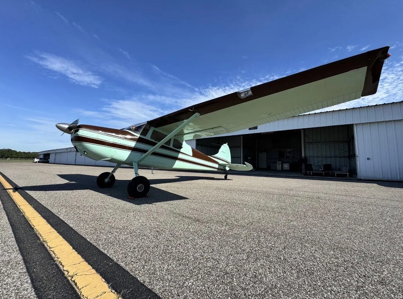
CESSNA 170B for sale now


Free — save the 170B to your watchlist and track it in one place.
More CESSNA 170Bmanuals & documents
See all 41 →- Dynon Certified SkyView HDX Systems DescriptionSystems Description
- Cessna 170 & C305A (USAF O‐1A) T3 Tailwheel Suspension System Installation InstructionsWeight And Balance
- Instructions for Continued AirworthinessSystems Description
- Service Bulletin: SB-001 Rev CService Bulletins
- Component Maintenance Manual for External Design Wheels ...Maintenance Manual
- Instructions for Continued Airworthiness No. ICA17025Weight And Balance
- Technician’s Service GuideTraining Manual
- Aviation Safety Letter ASL 2/2020Emergency Procedures
- Emergency ProceduresEmergency Procedures
- FAA PARTS MANUFACTURING APPROVALS (PMA) & SUPPLEMENTAL TYPE CERTIFICATE APPROVALS (STC)Supplemental Type Certificate
- Type Acceptance Report TAR 8/21B/24 – Cessna 170 SeriesMaintenance Manual
- Cessna Flyer - April 2015Other Documents
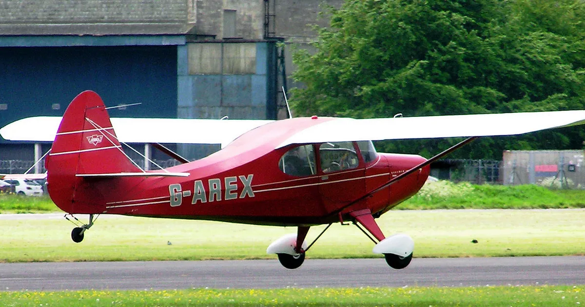
If you fly the CESSNA 170B, you may also be researching these.




In this document
Specifications
The Cessna 170 60E G2 has a wingspan of 86.7 inches (2204 mm) and a weight of 9 lb 3 oz (4171 g) when ready to fly with a 6S 5200 mAh battery. It is powered by a Potenza 60L 540kv Brushless Motor and includes a Potenza 100A ESC.
Battery Charging Guidelines
It is recommended to use an advanced Li-Po balancing charger for the Cessna 170 60E G2. The ideal battery is a 6S 4200-6200 mAh 40C+ Li-Po. Users should follow all manufacturer instructions for battery and charger to prevent fire hazards.
Pre-flight Checklist
The pre-flight checklist includes inspecting all components, ensuring proper installation of the rudder, tailwheel, landing gear, and wings, and verifying that control surfaces are functioning correctly. Pilots should also check battery connections and ensure the aircraft is balanced.
Safety Warnings and Precautions
The manual emphasizes the importance of following safety guidelines to prevent injury and damage. It advises against flying in visible moisture and stresses the need for adult supervision for users under 14 years of age.
Aura 8 AFCS Overview
The Aura 8 Advanced Flight Control System is pre-installed and enhances the flying experience by providing stability and control. It features multiple flight modes tailored for different flying styles, including sport and advanced aerobatics.
Safety notes
- Follow all instructions provided by your battery and charger manufacturer to prevent fire hazards.
- Inspect the model and all components before every flight to ensure safety.
- Keep the propeller area clear of loose items to prevent entanglement.
Full document text
w w w.f lexinnovations.com DESIGNED BY: 1 BEFORE CONTINUING WITH THIS INSTRUCTION MANUAL OR ASSEMBLY OF YOUR CESSNA 170 60E G2, PLEASE VISIT OUR WIKI SUPPORT SITE FOR THE LATEST PRODUCT UPDATES , FEATURE CHANGES, MANUAL ADDENDUMS AND FIRMWARE CHANGES FOR BOTH YOUR CESSNA 170 60E G2 AND THE INSTALLED AURA 8 ADVANCED FLIGHT CONTROL SYSTEM. wiki.flexinnovations.com/wiki/Cessna170G2 wiki.flexinnovations.com/wiki/Aura STOP 2 TABLE OF CONTENTS Introduction 2 ................................................................................................. Includes/Requires 2 ....................................................................................... Specifications 3 ............................................................................................... Replacement Parts Listing 3 ....................................................................... Optional Items 3 ............................................................................................. Completion Items 3 ....................................................................................... Battery Charging Guidelines 3 ................................................................... Special Language Definitions 4 ................................................................... Important Information Regarding Warranty 4 ....................................... Safety Warnings and Precautions 4 ............................................................ Low Voltage Cutoff 4 ....................................................................................... Rudder and Tailwheel Installation 5 ........................................................... Main Landing Gear Installation 6 ................................................................ Horizontal Stabilizer Installation 7 ............................................................. Main Wing Installation 8 ................................................................................ Main Wing Installation (continued) 9 ........................................................ Night Cessna 170 60E G2 LED Connections 10 ...................................... Connecting a Battery to the LED Controller 10 ..................................... Linkage Setup 11 .............................................................................................. Aura 8 AFCS 11 .................................................................................................. Transmitter Setup 12 ....................................................................................... Receiver Installation 12 .................................................................................. Servo Connections 13 ..................................................................................... Connecting your Receiver to Aura 13 ....................................................... Connecting your Receiver to Aura (continued) 14 ............................... Connecting Battery/Arming ESC 14 .......................................................... ESC Throttle Calibration 14 ........................................................................... Control Direction Test 15 ............................................................................... Aura Sensor Direction Test 16 ...................................................................... Prop Adapter, Propeller and Spinner Installation 17 ........................... Battery Installation 18 ..................................................................................... Center of Gravity 18 ......................................................................................... Pre-flight Checklist 19 ..................................................................................... AMA Safety Code 19 ........................................................................................ Optional Advanced Cessna 170 60E G2 Aura Configuration 20 ...... Flying your Cessna 170 60E G2 21 ............................................................. Airframe Repairs 22 ......................................................................................... Replacing Servos 22 ........................................................................................ Aircraft Troubleshooting Guide 23 ............................................................. Limited Warranty 24 ........................................................................................ Compliance Information for the European Union 24 .......................... INTRODUCTION The officially licensed Cessna 170 60E G2 offers something incredible for everyone. At first glance, it is a forgiving general aviation aircraft with rough field capabilities but take a deeper look into the heart of the Cessna, and you’ll find its expansive capability. From wild 3D aerobatics to gentle touch and goes on the water, this incredible aircraft offers a perfectly balanced airframe for all flying styles. Combine such an incredible airframe with today’s most Advanced Flight Control System, the Aura 8 AFCS (included), you’ll get an unmatched flying experience unavailable anywhere else. The Cessna 170 60E G2 is the second generation of the extremely popular and successful Flex Innovations Cessna 170 60E. Improvements from the Flex Innovations’ Design Team and valuable feedback from our customers around the world have been incorporated to take the Cessna 170 60E G2 to the next level! The Aura 8 AFCS has been further optimized and better matched to the airframe. And, as usual, the Aura 8 AFCS allows you the freedom to adjust all settings for your own flying style. The Cessna 170 60E G2 can also accept a wide range of options and accessories, including floats for flying off water, and snow skis for flying off snow. Leading edge slats can also be fitted, and a glider tow mechanism is built into the airframe. The Cessna 170 60E G2 is the go-to, all around perfect airplane for
Show full textShow less
maximum fun and minimal hassle. From sport flying, touch and goes, to 3D aerobatics and float flying, the Cessna 170 60E G2 is sure to be your favorite daily flier that can do it all! • Low wing loading offers superb stability at slow speed. • Custom-tuned Aura 8 gyro stabilization system provides the ultimate in stability and control • Powerful 60-sized motor provides the punch for demanding tasks • Hight Quality 32-bit Potenza 100A ESC • (6) High-precision DS34 digital servos • Light weight EPO foam for light weight aircraft • Navigation Lights with Day or Night version • Hollow carbon and plywood-reinforced wing is stiff and lightweight • Custom-designed control horns to maximize control geometry and performance • Large control surfaces for positive control at any air speed • Bush wheels to handle rough terrain and enhance the scale appearance. INCLUDES • Cessna 170 60E G2 airframe with decals applied • Aura 8 Advanced Flight Control System (programmed and ready to use) • Potenza 60L 540kv Brushless Motor • Potenza 100A ESC 32 bits with 5.5V/8A SBEC • (6) Potenza DS34 High Performance Digital Servo REQUIRES • 6+ Channel computer transmitter • 6S 4200 - 6200mAh 40C+ Li-Po Battery • Serial-Capable receiver • 6S Li-Po capable battery charger 3 86.7 in. (2204mm) 60.1 in. (15 44mm) 9lb. 3oz. (4171g) RTF with 6S 5200mAh motor battery & Potenza 60 Light 540 KV Brushless Motor (FPZM1060L) Potenza 100A ESC with Internal 8A BEC (FPZE100ABEC) Potenza DS34 Digital Metal Gear Mini Servo (FPZDS34) Aura 8 Advanced Flight Control System (FPZAURA08) 16 x 6 Electric SR Propeller (FPMP1606E) NEEDED TO COMPLETE 4200-6200mAh 6S 22.2V 40C+ LiPo (FPZB42006S40, FPZB52006S40, FPZB62006S40) NEEDED TO COMPLETE 6+ Channel Computer Transmitter NEEDED TO COMPLETE RECEIVER Serial-Capable Receiver SPECIFICATIONS REPLACEMENT PARTS LISTING FPM4470 Cessna 170 60E G2: Super PNP Orange FPM4480 Cessna 170 60E G2: Super PNP Night Orange FPM447001 Cessna 170 60E G2: Fuselage Orange FPM44801 Cessna 170 60E G2: Fuselage Orange Night FPM447002R Cessna 170 60E G2: Right Wing Panel Orange FPM447002L Cessna 170 60E G2: Left Wing Panel Orange FPM448002R Cessna 170 60E G2: Right Wing Panel Orange Night FPM448002L Cessna 170 60E G2: Left Wing Panel Orange Night FPM447003 Cessna 170 60E G2: Tail Set Orange FPM447004 Cessna 170 60E G2: Hatch Set / Cowling Orange FPM447006 Cessna 170 60E G2: Main Wheel Set Black Hub FPM447008 Cessna 170 60E G2: Pushrod Set FPM447009 Cessna 170 60E G2: Hardware Set FPM447011 Cessna 170 60E G2: Orange Decal Set FPZE100ABEC Potenza 100A ESC w/8A BEC FPZM1060L5 Potenza 60L Motor 8mm Shaft w/Collar FPZM1060L4 Potenza Bearing Set 60L 8mm FPM447014 Cessna 170 60E G2: Float Set & Struts w/ LED Light Orange FPM447015 Cessna 170 60E G2: Leading Edge Slat Set Orange FPM447007 Cessna 170 60E G2: Leading Edge Slat Set Red/ Gold FPM447018 Cessna 170 60E G2: Landing Gear Mount FPM3170141 Cessna 170 60E G2: Float Set Water Rudder Parts FPM317007 Cessna 170 60E G2: Tube Joiner Set FPM317008 Cessna 170 60E G2: Wing Strut Set FPM317012 Cessna 170 60E G2: Spinner FPM317013 Cessna 170 60E G2: Main Scale Wheel Set FPZDS34 Potenza DS34 Digital Metal Gear Mini Servo FPZDS15F Potenza DS15 MG Digital Sub-Micro Servo (Floats) FPZM1060L Potenza 60 Light 540 KV Brushless Motor FPZM10603D2 Potenza 60L, 60 3D, 65 3D, 70 Motor X- Mount w/ Screws FPZM1060L1 Potenza 60L Motor Bolt-on Adapter FPM317016 Cessna 170 60E G2: Snow Ski Set FPM317017 Cessna 170 60E G2: Glider Tow Pushrod FPZA1016 Potenza Advanced R/C LED Controller (6s) OPTIONAL ITEMS FPM447014 Cessna 170 60E G2: Float Set & Struts w/ LED Light Orange FPM317020 Cessna 170 60E: Wing Bag Set FPZB42006S40 Potenza 6S 4200mAh 40C Li-Po Battery FPZB52006S40 Potenza 6S 5200mAh 40C Li-Po Battery FPZB62006S40 Potenza 6S 6200mAh 40C Li-Po Battery ISDTD2 ISDT D2 200W AC/DC Charger FPZA1010 Potenza Digital Battery Analyzer SPM4651T DSMX SRXL2 Serial Telemetry Receiver FUTT6K Futaba T6K Transmitter with R3006SB Rx Mode 2 FUTR2001SB Futaba R2001SB SFHSS S-Bus FPM317016 Cessna 170 60E: Snow Ski Set FPM317017 Cessna 170 60E: Glider Tow Pushrod COMPLETION ITEMS INSTALLED! INSTALLED! INSTALLED! INSTALLED! INCLUDED! WARNING FOLLOW ALL INSTRUCTIONS PROVIDED BY YOUR BATTERY AND CHARGER MANUFACTURER. FAILURE TO COMPLY CAN RESULT IN FIRE. The assembly of the Cessna 170 60E G2 can be accomplished in less than one hour. Prior to assembling the airplane, it is advisable to charge your battery so that you are ready to begin setup upon completion of the assembly of your model. We recommend the use of an advanced Li-Po balancing charger, such as the ISDT D2 Dual 100W Multi Chemistry AC/DC balancing charger for your batteries to get the maximum performance and lifespan from them. Our airplanes are designed around our Potenza LiPo batteries, and we recommend the Potenza 6S 5200mAh 40C LiPo in the Cessna 170 60E G2 based on our extensive testing and development. These batteries feature an EC5 connector, so no soldering is required for use in your Cessna 170 60E G2. All are available online at www.flexinnovations.com and your local Flex Innovations retailer. SPECIFICATIONS Recommended battery – 6S 4200mAh-6200mAh 40C+ Li-Po BATTERY CHARGING GUIDELINES 4 SPECIAL LANGUAGE DEFINITIONS The following terms are used throughout the product literature to indicate various levels of potential harm when operating this product: NOTICE: Procedures, which if not properly followed, create a possibility of physical property damage AND a little or no possibility of injury. CAUTION: Procedures, which if not properly followed, create the probability of physical property damage AND a possibility of serious injury. WARNING: Procedures, which if not properly followed, create the probability of property damage, collateral damage, and serious injury OR create a high probability of serious injury. WARNING AGES 14+ This product is not intended for use by children under 14 years without direct adult supervision. ATTENTION Read the ENTIRE instruction manual to become familiar with the features of the product before operating. Failure to assemble or operate the product correctly can result in damage to the product, personal property, and cause serious or fatal injury. All instructions, warranties and other collateral documents are subject to change at the sole discretion of Flex Innovations, LLC. For up-to-date product literature, please visit our website at www.flexinnovations.com and click on the Cessna 170 60E G2 and Aura 8 product pages. IMPORTANT INFORMATION REGARDING WARRANTY Please read our Warranty and Liability Limitations section before building this product. If you as the Purchaser or user are not prepared to accept the liability associated with the use of this Product, you are advised to return this Product immediately, in new and unused condition, to the place of purchase. SAFETY WARNINGS AND PRECAUTIONS Protect yourself and others by following these basic safety guidelines. 1. This manual contains instructions for safety, operation and maintenance. It is essential to read and follow all the instructions and warnings in the manual, prior to assembly, setup or use, in order to operate correctly and avoid damage or serious injury. 2. This model is not a toy, rather it is a sophisticated hobby product and must be operated with caution and common sense. This product requires some basic mechanical ability. Failure to operate this product in a safe and responsible manner could result in injury or damage to the product or other property. 3. This model must be assembled according to these instructions. Do not alter or modify the model outside of these instructions provided by Flex Innovations, LLC, as doing so may render it unsafe and/or un-flyable. It is your responsibility to ensure the airworthiness of the model. 4. Inspect and check for the correct operation of the model and all its components before every flight. 5. If you are not an experienced pilot or have not flown a high-performance model before, it is recommended that you seek assistance from an experienced pilot in your R/C club for your first flights. If you’re not a member of a club, the Academy of Model Aeronautics (AMA) has information about clubs in your area whose membership includes experienced pilots. 6. Keep the propeller area clear from such items such as loose clothing, jewelry, long hair, or tools as they can become entangled. Keep your hands and body parts away from the propeller as injury can occur. 7. Never fly in visible moisture or submerge the airplane or any of its electronic components in water. Permanent damage to electronic components may occur, or corrosion of components may lead to intermittent failures. LOW VOLTAGE CUTOFF Li-Po batteries have a nominal (rated) voltage of 3.7v per cell, and fully charged, reach 4.2v per cell. Batteries are designed to be discharged below the nominal voltage, however, if they are discharged below 3.0v per cell, damage will occur and the pack will loose capacity. For best long term battery life, set a timer and land after a time that leaves approximately 15% of the battery’s capacity remaining. Low voltage cutoff is a feature that is built into the Potenza 100A ESC that is designed to protect the connected battery from being discharged too far and causing permanent damage to the cells. Circuitry within the ESC will automatically detect when the input voltage from the battery pack reaches below 3.0V per cell (average) and will remove power to the motor, but still deliver power to the servos so that a safe landing may be made. If the motor begins to lose power rapidly during flight, the LVC has sensed that the total voltage of the pack has dropped below 3.0V per cell average, and the airplane should be landed immediately. 5 RUDDER AND TAIL WHEEL INSTALLATION Required Tools and Fasteners: Medium CA or 15min Epoxy (3) M3x10 Phillips Head Self-Tapping Screw #2 Phillips Screw Driver (1) M2 x 10 Phillips Head Machine Screw #1 Phillips Screwdriver (2) M2 Flat Washer Needle Nose Pliers (1) M2 Lock Nut 1. The rudder comes pre-hinged to a small section of vertical fin. Test fit the rudder and fin section onto the fuselage. Remove it from the fuselage once fit is confirmed. 2. Lay the fuselage on its side, and using medium CA (foam-safe is not required), apply an adequate amount to the fuselage. Press the rudder and vertical fin section into the fuselage, being sure to wipe away any excess CA. 3. Secure the lower plastic support in place by threading an M3x10 Phillips head self-tapping screw through the bottom of the plastic part in the fuselage. Do not fully tighten, as you can cause the rudder to bind. A small amount of play is needed here. 4. Allow time for the CA to dry, and once dry, check for proper rudder movement. Be sure the rudder moves freely with little to no binding. 5. Press the tailwheel wire into the plate on the bottom of the rudder. Lay the tailwheel plate over the wire, and secure it in place with two M3x10 Phillips head self-tapping screws. 6. Install the rudder pushrod ball-link on the control horn using the innermost hole as shown in the diagram below. Secure it using a #1 Phillips screwdriver, needle nose pliers, and the following components: (1) M2x10 Phillips Head Machine Screw (2) M2 Flat Washer (1) M2 Lock Nut. 6 MAIN LANDING GEAR INSTALLATION Required Tools and Fasteners: #2 Phillips Screw Driver (4) M3x10 Phillips Head Self-Tapping Screw 1.5mm Hex Driver (2) M5 Lock Collars, with Set Screws (2) M5 Spacers 1. Slide an M5 spacer over the landing gear wire. 2. Slide a main wheel over the landing gear wire, followed by a lock collar. Add a drop of blue thread lock to the set screw, and secure it in place. Repeat for the other wheel. 3. Push the landing gear wire into the bottom of the fuselage. Orientation of the wire landing gear does not matter, however, the plastic wire covers are directional. You should have more material AFT of the landing gear wire. Insert the plastic landing gear keeper after the landing gear, noting orientation. The plastic part will sit flush in one orientation, but in the wrong direction, may not sit flush. 4. Secure the plastic landing gear plate into the fuselage using 4 M3x10 self-tapping Phillips head screws. Do not over-tighten. Press the tailwheel wire into the plate on the bottom of the rudder. Lay the tailwheel plate over the wire, and secure it in place with two M3x10 Phillips head self- tapping screws. 7 HORIZONTAL STABILIZER INSTALLATION Required Tools and Fasteners: Clear Tape (4 Strips) (1) M2x10 Phillips Head Machine Screw #1 Phillips Screwdriver (2) M2 Flat Washer Needle Nose Pliers (1) M2 Lock Nut 1. Insert the horizontal stabilizer tube into one of the horizontal stabilizer halves. 2. Slide the tube through the hole in the fuselage, being sure to orient the control horn towards the bottom of the airplane. Do not force it into place. 3. Slide the other stabilizer half onto the tube, being sure to index the elevator joiner tabs into one another. Do not force it into place. 4. Apply 4 pieces of clear tape to the joint between the stabilizer and the plastic mounts. Be sure to apply tape to both the top and bottom sides of the stabilizer. 5. Install the elevator pushrod ball-link in the control horn using the innermost hole as shown in the diagram below. Secure it using a #1 Phillips screwdriver, needle nose pliers, and the following components: (1) M2x10 Phillips Head Machine Screw (2) M2 Flat Washer (1) M2 Lock Nut. 8 MAIN WING INSTALLATION Required Tools and Fasteners: #2 Phillips Screw Driver (4) M3x25 Phillips Head Machine Screws (4) 6mm Strut Retaining Pins (4) Strut Retaining Pin Keepers 1. Insert the main wing tube into one of the main wing halves. 2. Slide the tube through the hole in the fuselage. Connect the all-in-one servo lead to the receptacle in the wing. 3. If you have a night version, connect the wing JST to the LED controller JST. 4. Slide the other wing half onto the tube, and make any connections as completed in the previous step. Fully seat the wing into the plastic mounts in the fuselage. Do not force it into place. 5. Secure each wing panel to the fuselage using 2 M3x25 Phillips head machine screws. Don't over tighten. 9 MAIN WING INSTALLATION (CONTINUED) 5. Note which wing strut goes to each wing panel, and which end goes to the wing and to the fuselage The struts are labeled R and L at one end of the strut. Also note that there are two different strut retaining pins; one that is shorter (A) and one that is longer with a "D" shaped head (B). Pin A goes to the fuselage side, and Pin B goes to the wing side of the strut. 6. Insert a strut retaining pin through the end of the strut AND the mount in the wing. Slide a retaining pin keeper through the hole in the retaining pin to secure it in place. 7. Repeat step 6, but for the plastic mount in the bottom of the fuselage. The strut goes ABOVE the mount in the fuselage. Note that for faster field assembly, it is recommended to leave the strut attached to the wing panel, and only remove it from the fuselage. The strut will lay flat on the wing for storage. 8. Confirm the linkage locations in the servo arm and control horn for both flaps and ailerons, referencing the images below. Adjust as necessary. Note that the flap should be neutral (even with the aileron) with the flap servo arm perpendicular to the flap servo case. FLAP AILERON MAIN WING CONTROL LINKAGE SETUP 1. 2. A - Fuselage Side B - Wing Side 10 LED Controller Two Wing Connections Float Connection Stab Spotlight Connection NIGHT CESSNA 170 60E G2 LED CONNECTIONS If you have purchased the Night version of the Cessna 170 60E G2, this page will cover all LED light connections. If you did not purchase the night version, skip ahead to the next page. 1. There are two connections for each wing panel, one at the leading edge, and one at the trailing edge of the wing. Connect the one at the trailing edge to the installed JST extension. Route the connector at the leading edge through the hole in the fuselage and plug into the LED controller directly. 2. If using the floats with lights, connect each JST for the float set to the LED controller in the fuselage. Route the leads through the cooling hole in the bottom of the fuselage. Secure the wire to the flat strut and fuselage using water proof tape. LED CONTROLLER 3S Li-Po Black/Negative Lead CONNECTING A BATTERY TO THE LED CONTROLLER The LEDs on your aircraft are switchable via the transmitter, and are designed to be powered by 12 volts (3S Li-Po) through the 6S JST-XH balance tab on the LED controller. By default, the LED controller is left unplugged. If the servo lead of the LED controller is not plugged into the Aura or a receiver, the LED controller will default in the ON position when powered, allowing the Night Version to be flown at night with a basic 6-channel transmitter or receiver. IN ORDER TO CONTROL THE LEDS FROM THE TRANSMITTER, YOU MUST USE A STANDARD RECEIVER THAT IS CAPABLE OF 7+ CHANNELS, AND KEEPS THE SERVO PORTS ACTIVE WHEN USING A DIGITAL DATA STREAM (like S.Bus, SRXL etc.). WARNING You MUST use an independent 3S Li-Po battery to power the LEDs in the Cessna 170 60E G2. Failure to do so can damage your flight batteries. We recommend the use of thePotenza 3S 2200mAh 45C Li-Po (FPZB22003S45) or the Potenza 3S 500mAh 25C Li-Po (FPZB5003S25). WARNING Do not leave the battery plugged into the LED controller for extended periods of time. Doing so can damage the battery. Average current draw for the lighting system is 2.2A/h 11 AURA 8 AFCS The Aura 8 AFCS (Advanced Flight Control System) comes programmed and pre-installed in your Cessna 170 60E G2, making setup a breeze. This highly-refined 3-axis gyro makes the Cessna 170 60E G2 fly like it is a larger aircraft and in less wind. Thanks to the Aura’s advanced implementation, it not only enhances the flying experience, but it never interferes with the pilot’s control. The Aura 8 AFCS comes configured with Flight Modes (dual rates, expos and gyro settings) set by the Flex Innovations team, and offers a great starting point for most pilots. Since these are already configured for you in the Aura, there is no need to set up dual rates, expos or flaps in your transmitter. Simply follow the Transmitter Configuration Guide in this manual for complete details on the transmitter programming required for the Cessna 170 60E G2 and Aura 8 AFCS. Visit wiki.flexinnovations.com/wiki/Aura for the latest Aura-related product information and updates. Description of Pre-Loaded Aura Flight Modes Flight Mode 1: Sport (Gyro Off) • For sport flying, test flights or safety. • Rates and Expos are tuned for sport flying. • Gyro gain is set to off. Flight Mode 2: Sport (Gyro On) • For sport flying. • Rates and expos are tuned for sport flying. • Gyro is set to low. Flight Mode 3: Advanced (Gyro On) • For advanced aerobatic flight. • Rates are highest and expos are tuned for 3D flight. • Flaps are coupled with the ailerons for maximum roll rate and authority. • Gyro is set to moderately high. In all Flight Modes, the flaps function with the operation of CH6 (Aux 1) on the transmitter. NOTE - Aileron travel will not change with the flight mode switch. The addition of flaps with the ailerons significantly increases the roll rate, making the change feel like a low versus high rate. NOTE - Rudder stick movement will also move the ailerons and elevator. Flap (CH6) movement will also move the elevator. This is NORMAL and is the pre-programmed mixing.. Each of the modes has been tuned by our team to offer a solid start. Because tastes in control feel are unique, if changes in rate and expo are needed adjustments should be made through Aura. Changes on gain value can only be made through the Aura. The Aura 8 AFCS Profile for the Cessna 170 60E G2 can be changed from the Stock Cessna 170 60E G2 Profile to the Advanced Cessna 170 60E G2 Profile without the need of a computer. For further details, please see the section of this manual titled Optional Advanced Cessna 170 60E G2 Aura Configuration on page 20. Note: to use the Advanced Cessna 170 60E G2 Profile you will need a 7 channel radio. LINKAGE SETUP As you set up your receiver and you Aura 8 mechanically adjust the control linkages so that the surfaces are neutral with zero trim and zero sub- trim. Final trim adjustments may be required during flight. For more information on flight trimming, please refer to the trimming section located on page 21 of this manual. The Cessna 170 60E G2 has ball links on both ends of all control surfaces. If an adjustment is necessary remove the screw assembly on one end, turn the ball link as necessary and re-attach the screw assembly. On all control surfaces the ball links attach to the outermost hole on the servo arm and the innermost hole on the control horn as shown below. NOTICE The DS34 servos installed in your Cessna 170 60E G2 are high quality, digital servos with metal gear train and ultra-fine gear mesh. This fine resolution and high tooth count output shaft means that the servo arms pre-installed on the servos may inadvertently be misaligned, yet appear properly installed. It is critical to ensure the positive, perpendicular orientation of the arm to the case to ensure that the travel of the servos is even from side to side at extreme throws. Servo Arms Control Horns 12 TRANSMITTER SETUP The included Aura 8 is designed to work seamlessly with all popular transmitter and receiver brands, however, transmitter setup is significantly different than when setting up a model without Aura. Follow these steps: 1. Start with a new model memory in your transmitter. Reset it to be certain it is set to defaults. 2. Adjust your transmitter settings according to the Transmitter Configuration Guide below. 3. Make ONLY the changes shown in the Transmitter Configuration Guide. No other changes are required. Transmitter Configuration Guide Spektrum, Futaba, JR¹ & Graupner FrSky Jeti (EX-Bus) Wing/Tail Type 1 Aileron, 1 Elevator, 1 Rudder 1 Aileron, 1 Elevator, 1 Rudder 1 Aileron, 1 Elevator, 1 Rudder End Points (Travel Adjust or ATV) Ail/Ele/Rud – 125% Ail/Ele/Rud – 100% Aileron/Ele/Rud – 100% Thro/CH5/CH6 – 100% Thro/CH5/CH6 – 84% Thro/CH5/CH6 – 80% Reversing Not Allowed² Sub-Trim Verify at Zero, NOT ALLOWED Trim Levers Verify at Zero CH5 (Gear) – Flight Mode Assign to a 3 Position Switch CH6 (Aux 1) – Flaps Assign to a 3 Position Switch (Do NOT use Transmitter Flap System) First Flight Timer³ For your first flight, set to 5:30 1 JR customers should use JR XBUS Mode A, and follow the chart above. This is the preferred JR DMSS connection to Aura. 2 If you are using a Futaba transmitter, please note that some Futaba transmitters have the throttle set to reversed by default. We recommend that you leave the reversing set to the defaults and reverse it if needed after testing. NOTE: do all throttle testing with the prop removed! 3 This time is a safe starting point for most pilots. This aircraft can typically fly anywhere between 5-1/2 to 10 minutes (with 6S 5200mAh Li-Po), depending on an individual’s flying style. FOR CUSTOMERS USING TRANSMITTERS OTHER THAN WHAT IS LISTED IN THE CHART ABOVE, PLEASE VISIT OUR WIKI PAGE FOR INSTRUCTIONS SPECIFIC TO YOUR TRANSMITTER AND RECEIVER BRAND HITEC – wiki.flexinnovations.com/wiki/Aura/HitecSbusUse RECEIVER INSTALLATION Choosing a Receiver Aura will auto-detect modern serial receiver connections. For use in the Cessna 170 60E G2, only a serial receiver connection or a Spektrum Remote Receiver can be used. Below are a few examples of serial receivers that can be used with the Aura 8. This is not a complete list of compatible receivers, rather a short list to assist in your receiver selection. Spektrum Remote Receivers – SPM9745 (2 Required) Spektrum SRXL – SPMAR6610T, SPMAR8020T, SPMAR10100T Spektrum SRXL2 – SPM4651T, SPM4650 Futaba S.Bus – Futaba R7008SB, R2001SB, R6202SBW Hitec S.Bus – Optima SL, Maxima SL FrSky S.Bus – RX4R, RX6R Graupner HoTT (Sum D of 8) – GR12L, GR16L JR XBus (Mode A & Mode B) – RG012BX, RG613BX, RG821BX Jeti EX-Bus – REX10, R9 EX, REX6 A PPM (8CH, negative shift, approximately 22ms/frame) receiver may also be connected into Port ‘B’, however Aura will not auto-detect and setup must be performed through the Aura Config Tool (Windows Application). 13 DEFAULT AURA CONNECTIONS S1 – Throttle S2 – Left Aileron S3 – Right Aileron S4 – Elevator S5 – Rudder S6 – Left Flap S7 – Right Flap S8 – Water Rudder (optional, with floats) Port B – Serial Receiver Input Mini Port A&B – Remote Receiver Inputs Mini Port A Mini Port B Micro USB Port Port B CONNECTING YOUR RECEIVER TO AURA Note: The Spektrum 4651T receiver requires the use of a different cable to connect to Aura. The cable is included with the receiver when it is purchased directly from Flex Innovations. You can also purchase the cable itself at flexinnovations.com (FPZA1039). Spektrum Remote Receivers If using two Spektrum Remote Receivers, connect them to Aura Mini Port A and Mini Port B using the cable provided with your receivers. Serial Receivers If using a standard serial receiver, connect the provided male to male cable to your receiver’s serial port. Connect the other end of the cable to Aura Port B noting proper polarity. Note: If you are using Futaba S.Bus, be sure to use the proper S.Bus port in your receiver. DO NOT use the S.Bus2 port, as it is not supported for use with the Aura 8. Refer to your manufacturer's instructions for proper S.Bus use. Note: When using Spektrum SRXL to connect to the Aura, always connect the remote receivers to the Spektrum receiver, NOT to the Aura. 4651T ESC - + - + ESC Binding Your Receiver 1. With the transmitter and aircraft powered OFF, place a bind plug into Aura Port S8. 2. Power on the aircraft. Your remote receiver should flash rapidly, indicating it is in bind mode. 3. Bind your transmitter to the remote receiver per your transmitter manufacturer’s instructions. This is typically done by pressing and holding the bind button on your Spektrum transmitter while powering it on. 4. Verify the receivers are bound by looking at the LED on the Remote Receivers. This is typically indicated by a solid orange LED on Spektrum Remote Receivers. 5. Remove the bind plug from Aura Port S8. Binding Your Receiver Bind your receiver to your transmitter per your receiver and transmitter manufacturer’s instructions. SERVO CONNECTIONS 14 ESC THROTTLE CALIBRATION In order to map the full range of the ESC output to your throttle stick motion you will have to preform an ESC throttle calibration. NOTE: Execute ESC throttle calibration with the propeller and spinner removed. 1. Power on your transmitter, DISABLE any throttle hold or throttle kill switches, completely lower the throttle trim and set the stick to full throttle. 2. Connect the flight pack to your Cessna 170 60E G2. 3. Listen for the tones coming from the ESC through the motor, after about 2 seconds you should hear two tones. 4. Pull your throttle stick back to idle. 5. Listen for the ESC arming tones from the motor. The ESC throttle range has now been properly calibrated, and is stored in the ESC's memory until it is calibrated again. You can repeat this process as many times as necessary. CONNECTING BATTERY/ARMING ESC Observe the following procedures to safely power up your model after it has been bound. Ensure propeller is removed unless this sequence is followed to power up before flight. 1. Turn on the transmitter. Lower the throttle stick AND throttle trim to their lowest settings. Be sure to wait for your transmitter to indicate it the radio signal is being broadcast before proceeding If a battery is connected to the ESC with the throttle fully open on the transmitter, the ESC will enter programming mode. If this occurs, simply disconnect the battery, lower the throttle and reconnect the battery. 2. Ensure the aileron, elevator and rudder gimbals are centered. 3. With the airplane on a solid surface, connect the battery to the ESC and wait. The ESC will make the motor emit a series of audible tones during its initialization process. 4. The ESC will make the motor emit a short, final tone sequence indicating that the ESC is now armed and that the motor will spin in response to throttle stick movement. WARNING When making adjustments to linkages, transmitter settings, or the Aura 8 flight control system, remove the propeller to guard against accidental spool up. WARNING Hold aircraft securely when connecting the battery before flight. Always ensure that the propeller is clear of any and all objects as they may become entangled. CAUTION Always connect the battery when the throttle stick and throttle trim are in the idle/cut-off position. Aura 8 Auto-Detect Once your receiver is bound, powered, and connected to the Aura, the Aura will begin the Auto-Detect process to learn what type of receiver you are using and set itself up for that specific system. Auto-Detect is indicated by a series of sweeping LEDs of various colors. After Auto-Detect is completed, verify that Aura is on and receiving data from your receiver by looking at the LEDs on the Aura. Ready-To-Fly: Solid Orange LED: Aura On and Calibrated Solid Green LED: Aura receiving Valid receiver data Possible Errors: Flashing Orange LED: Aura Moved During Power Up No Green LED: Aura NOT receiving receiver data CONNECTING YOUR RECEIVER TO AURA (CONTINUED) 15 CONTROL DIRECTION TEST Refer to the chart below to determine the proper control surface responses to transmitter control inputs. If controls are reversed, DO NOT REVERSE CONTROLS IN YOUR TRANSMITTER OR IN THE AURA CONFIG TOOL. Email us at support@flexinnovations.com for corrective action. Note that BOTH the Transmitter Control Direction Test AND the Flight Controller Sensor Direction Test MUST BE PASSED! IF EITHER ONE DOES NOT PASS, DO NOT FLY! NOTE: There is pre-configured rudder to aileron and rudder to elevator mixing programmed into the Aura. Simultaneous movement of these control surfaces with rudder input is intentional and completely NORMAL. Transmitter Command Proper Control Surface Deflection Stick Left Stick Right Stick Forward Stick Aft Stick Left Stick Right AILERON ELEVATOR RUDDER 16 AURA SENSOR DIRECTION TEST Perform a test of the gyro system to verify the corrections made for a given movement are correct. If any of the tests do not result in the correct reaction from the airplane's gyro system, DO NOT FLY THE AIRPLANE, and contact us via email at support@flexinnovations.com The flight control system activates with RF broadcast. Perform these tests in Mode 3 (higher gain) for better visibility and then in Mode 2, and any other modes that have gyro gains assigned. (By default, Mode 1 has no gain assigned). Control surface deflections are exaggerated in the pictures below for clarity. Please note that the control surfaces will move ONLY while the aircraft is being ROTATED. Aircraft Movement Proper Control Surface Deflection AILERON ELEVATOR RUDDER 17 PROP ADAPTER, PROPELLER AND SPINNER INSTALLATION Required Tools and Fasteners: 2.5mm Hex Driver (3) M3x9 Hex Head Machine Screws #1 Phillips Screwdriver (1) M3x30 Phillips Head Machine Screw Adjustable Wrench (1) Prop Washer Blue Thread Lock (1) Propeller Nut Note: Do not complete transmitter, receiver and/or Aura setup with the propeller installed. 1. Locate the bolt-on prop adapter for the motor. Apply blue thread lock to each of the three M3x9 hex head machine screws, and secure the prop adapter to the motor. Make sure that the propeller adapter seats fully against the motor face, and is concentric with the motor shaft. 2. Install the spinner backplate onto the motor shaft. Ensure that it is fully seated. 3. Install the propeller with the convex surface facing forward. The propeller size numbers are printed on the front face of the prop and should orient forward. 4. Slide the prop washer on the shaft with the widest face aft, and tighten the prop nut. 5. Install the spinner cone, and tighten the M3x30 Phillips Head screw using a #1 Phillips screwdriver. Do not apply blue thread lock and do not over tighten. 18 CENTER OF GRAVITY Setting the center of gravity (CG) is one of the most important steps for successful flight, particularly with a new airplane. The Cessna 170 60E G2 is an extremely capable airplane with large control surface throws and a high thrust to weight ratio. These factors make it an enjoyable aircraft to fly, but if the CG is not within an acceptable range, it will make the airplane difficult, if not impossible to control. Prepare the aircraft to its flight-ready state. This means all hardware, components and flight battery should be installed before proceeding. The center of gravity (CG) is measured from the trailing edge of the main wing toward the nose of the aircraft. Lift the aircraft upright, with all components installed, from the bottom of the wing at the CG location noted. The acceptable CG range for the Cessna 170 60E G2 is 83mm to 97mm (3 1/4 inches to 3 3/4 inches). Designer and multi-time world champion Quique Somenzini has found 90mm ( 3 1/2 inches) to be the sweet spot in the acceptable CG range based on his extensive test flights and experience. NOTICE The CG measurement should be made with the completed airframe with all components (batteries, servos, receiver, linkages, screws, bolts, hardware, etc.) installed. Failure to do so will result in inaccurate measurement. BATTERY INSTALLATION 1. Push the spring-loaded battery latch tab back to release the battery hatch. Lift the hatch away from the fuselage, starting at the front. 2. Remove the battery tray by loosening the thumb screw. Slide the tray forward as you gently lift the tray away from the fuselage. 3. Install an adhesive-backed hook strip to the battery tray, and an adhesive-backed loop strip to the battery. 4. Place the battery on the tray, and secure it in place with the hook and loop strap provided. 5. Re-install the tray into the battery compartment by aligning the rear tabs on the tray with the appropriate slots in the fuselage sub-frame. Once seated in place, secure the tray to the sub-frame using the thumb screw. 6. Reinstall the hatch, and confirm that the latch has positively engaged. WARNING When making adjustments to linkages, transmitter settings, or the Aura 8 flight control system, remove the propeller to guard against accidental spool up. CAUTION Always keep limbs clear from the propeller when the battery is connected. After the ESC arms, the propeller will rotate when the throttle is moved. Unlike an internal combustion engine, electric motors apply more voltage to counteract resistance, therefore any object that is entangled in the propeller will be severely damaged before the motor will stop 90mm (+/- 7mm) 3-1/2- inches (+/- 1/4-inch) 19 PRE-FLIGHT CHECKLIST To help ensure a successful first flight, as well as many flights after, perform a few simple pre-flight checks to be sure the aircraft is ready to fly: 1. Verify the elevators and rudder are properly hinged and in good working order. Pinch a control surface between your thumb and forefinger and grasp the stabilizers with your other hand. Attempt to move the control surface back and forth perpendicular to the wing (see Figure 1). Watch the hinges for movement. If you find any loose hinges, apply a small amount of medium CA to the mounting point, being sure to keep glue away from the hinge pivot. Wait 15-20 seconds, then apply CA accelerator to cure the CA. 2. Verify the flaps and ailerons are properly hinged and in good working order. Pinch a control surface between your thumb and fore finger, and grasp the wing with your other hand. Give the control surface a firm pull away from the wing. The control surface should not come unhinged from the wing. Be sure to avoid over-stressing the part, as an aggressive pull may cause the surface to come unhinged even though it is hinged properly. If hinging is loose, do not fly. Apply thin CA to the loose side(s) of the hinge(s) to re-secure. 3. Verify all control surfaces move freely when disconnected from the servo. If you have a tight or binding surface, apply a small drop of light oil to each hinge pivot. Move the surface back and forth to work the oil into the hinge. Repeat as needed.. 4. Verify that all hardware and other aircraft parts are properly secured, including those connections that require blue thread lock. This includes hardware and parts installed by the factory. 5. Verify your battery is fully charged and in good condition. Avoid using batteries with swollen cells, or batteries that do not charge back to their full capacity. 6. Verify the C.G. is in the proper location and the battery is secured in place. 7. Ensure the Aura is on and functioning properly. Power on your transmitter, followed by the aircraft. Ensure the Aura is calibrated properly and receiving a valid radio source (solid orange+solid green LEDs). 8. Verify transmitter stick inputs result in the proper control surface movements (reference page 15) and the Aura flight modes work properly. 9. Verify aircraft movement results in proper Aura sensor corrections (reference page 16). 10. Verify the motor and ESC function properly. Point the aircraft in a safe direction. Hold the airframe firmly, smoothly advance the throttle to full and back to idle. Listen and watch for any odd or unusual behavior for the motor or speed controller. AMA SAFETY CODE When flying your aircraft, we recommend following the guidelines set by the Academy of Model Aeronautics (AMA). You can find their safety handbooks as well as more information on the AMA at their website, located at the address below: www.modelaircraft.org Figure 1 - Test for hinge movement and loose hinges 20 OPTIONAL ADVANCED CESSNA 170 60E G2 AURA CONFIGURATION The Aura installed in your Cessna 170 60E G2 comes with the Quick Set feature programmed. Quick Set allows the user to switch between different Aura profiles without the use of a computer. These profiles are already configured by the Flex Innovations team. The two profiles on your Cessna 170 60E G2 Aura include the Stock Profile which is the default profile, described on page 11, and the optional Advanced Profile described below. The Advanced Aura Profile for the Cessna 170 60E G2 offers different Flight Modes that are more suited for intermediate to advanced pilots. In order to use the Advanced Cessna 170 60E G2 Profile, you will need a minimum 7 channel transmitter. If you wish to use crow, you will need a minimum 8 channel transmitter. If you wish to have a switchable Night LED setup, with crow, you will need a minimum 9 channel transmitter. Cessna 170 60E G2 Advanced Aura Profile CH 7 (Aux 2) | Gyro Kill Switch → Assign to 2-position switch CH 8 (Aux 3) | Crow Switch (Optional) → Assign to 2-position switch Flight Modes (CH5, Gear) Flight Mode 1: Sport (Gyro On) • For general flight • Rates are low and expos tuned for general flight. • Gyro is set set to low Flight Mode 2: Advanced (Gyro On) • For more advanced aerobatics like snaps and spins while at high airspeeds • Rates are moderately high and expos are tuned for comfortable flight • Flaps work in conjunction with ailerons for added roll authority • Gyro is set to low Flight Mode 3: Slow Speed 3D (Gyro On) • For slow speed, 3D flight • Rates are highest and expos are tuned for comfortable flight • Flaps work in conjunction with ailerons for added roll authority • Gyro is set to its highest setting and will oscillate in high speed flight. Do not fly at high airspeeds in this Flight Mode Quick Set Procedure Step 1 - Enter Quick Set Mode 1. Make sure all power is off on the Cessna 170 60E G2 2. Remove the prop before making changes 3. Turn on your transmitter 4. Remove the Servo lead from Aura Port S2. 5. Install a bind plug in Aura Port S2. 6. Plug in the motor battery to power up the Cessna 170 60E G2 7. The LEDs will repeatedly flash orange two times to indicate you are in Quick Set Mode. The green LED may be solid or flashing. Step 2 - Choose Profile 8. After entering Quick Set mode as described above, you toggle the Aura Flight Mode switch (CH5) on the transmitter to choose your Aura Profile. The Green LED indicates the selected Flight Mode. • If the Green LED is on SOLID, the Aura is set to use the Stock Aura Profile. • If the Green LED is FLASHING, the Aura is set to use the Advanced Aura Profile. 9. If you wish to activate Crow, you must select the Advanced Aura Profile (Green Flashing) from the previous step. After selecting the Advanced Profile, toggle the Crow Switch (CH8, Aux 3) to activate Crow. • If the RED LED is ON, Aura has set the Crow function to ACTIVE. • If the RED LED is OFF, Aura has set the Crow function to INACTIVE. Step 3 - Saving your Selections 10. After selecting your Profile, remove the bind plug to save your settings. All Aura LEDs will turn on while the Aura is saving, the return to their previous state. 11. Completely power off the Cessna 170 60E G2 and Aura 12. Replace the Servo Lead in Aura Port S2 13. Power up and Fly as usual with your new Aura Profile! Note: This process can be repeated as many times as desired to switch back and forth between Stock and Advanced Aura Profiles. 21 FLYING YOUR CESSNA 170 60E G2 Selecting a Flying Site Selecting a flying site is critical to a successful flight. Airplanes require a lot more room than other R/C products, therefore, a neighborhood or parking lot is less than ideal. A large open field with short grass and generous overfly area are the best candidates if no AMA field is available in your area. Know your overfly area - ensure that there are no houses, playgrounds, or other buildings that may be damaged if the airplane were to crash. Takeoff Taxi or place the aircraft on the runway centerline, with the nose pointed into the wind. Select Flight Mode 2, then set throttle trim so that the motor spins at its lowest RPM without stopping. For the first flight, leave the flaps in the up position. Smoothly advance the throttle to full while maintaining directional control with the rudder and slight back pressure on the elevator. The airplane should lift off smoothly before the throttle is fully open. Fly in Flight Mode 2 until the aircraft is fully trimmed (see special trimming instructions), and you are comfortable with its handling, then explore the other modes as desired. Flying Altitude is your friend on the first flight. Briskly climb to a safe altitude and trim the airplane out. The airplane should fly straight and level at 2/3 to 3/4 power with no hands on the transmitter. Try some basic maneuvers, and slowly progress into the airplane’s flight envelope as you become more comfortable with the airplane’s flight qualities and perfect your setup. Note: If at any time you experience unexpected control system inputs or oscillations, switch to Flight Mode 1 to turn the gyro off, land and troubleshoot the issue. Landing Be mindful of your flight time and allow adequate battery reserve for a couple of go-arounds, if necessary, on the first few flights. Select Flight Mode 2 and slow the airplane and align with the runway, into the wind. For your first landing, leave the flaps in the up position. The airplane should descend smoothly in this configuration with proper airspeed. Once you are close to the ground, gradually close the throttle fully and begin to smoothly apply up elevator as required to arrest descent and the airplane should gently touch down with a short roll out. Trimming The first several flights on your new Cessna 170 60E G2 should be dedicated to trimming and setup. Fly the airplane at 2/3 power in any Flight Mode you are comfortable flying in, and trim for level flight. DO NOT CHANGE FLIGHT MODES. Land, adjust linkages or execute Quick Trim (see below) and return the trim and/or sub-trim to zero and fly again. Repeat process until the airplane flies hands off, straight and level. Transmitter trim or sub-trim will cause trim shifts when different flight modes are selected. To eliminate this trim shift, the model should be mechanically trimmed, or Aura “Quick Trim” may be used instead. CAUTION USE CAUTION WHEN FLYING YOUR CESSNA 170 60E G2 IN MODE 3 AT HIGH AIRSPEEDS. DOING SO CAN INDUCE CONTROL SURFACE OSCILLATIONS AND MAY CAUSE A CRASH. Aura Quick Trim The Aura 8 features a Quick Trim Mode that eliminates the need for mechanical linkage adjustments during test flights. Aura will learn the trim values from your transmitter, and apply them to the control surfaces at power up when enabling quick trim mode. NOTE: Quick Trim can also be used BEFORE flying to make small changes to center the control surfaces before flight. 1. Fly the airplane in your preferred Flight Mode at 2/3 power. Trim the aircraft with the transmitter trimmers and land. DO NOT CHANGE FLIGHT MODES. 2. Power off the Cessna 170 60E G2. Insert a bind plug into Aura Port S3 (you will need to remove the servo lead that is currently in S3). Check the transmitter is on and re-power the Aura to enter Quick Trim. 3. Wait 5 seconds for the Aura to completely initialize. Confirm Quick Trim mode is active by checking the Blue LED is slowly flashing. 4. Remove the bind plug from Aura Port S3 to save your trim settings. Re-install the servo that was previously removed into port S3. Removing the bind plug stores the current trims in the Aura. The Blue LED will flash quickly after control surface trim values are stored. While the trim values are stored in Aura, they are not applied to the control surface(s) until the Aura is re- powered. 5. Remove power from the Cessna 170 60E G2 and center all control surface trims on the transmitter. 6. Re-power the Cessna 170 60E G2. The control surfaces should be unchanged even though the trim has been centered on the transmitter. 7. Switch between other Flight Modes to ensure you do not see any changes in trim. NOTE: QUICK TRIM MAY BE REPEATED AS NEEDED FOR FINE TUNING, OR IF CHANGES TO THE AIRCRAFT ARE MADE. NOTE: ENSURE AILERON/ELEVATOR/RUDDER SUB-TRIMS ARE AT ZERO IN THE TRANSMITTER BEFORE FLYING FOR THE QUICK TRIM PROCESS TO WORK PROPERLY. 22 REPLACING SERVOS Required Tools and Fasteners: #1 Phillips Screwdriver 1. Disconnect the servo from the Aura 8. 2. Unscrew the servo arm from the servo and remove the servo arm. 3. Unscrew the two servo mounting screws at each end of the servo and remove. Note that some servos may be connected to a servo extension. This extension should be left in the wing or fuselage when the servo is replaced. AIRFRAME REPAIRS The Cessna 170 60E G2 is molded from durable EPO foam and is repairable with most adhesives. Similar to building and repairing wood or composite airplanes, the correct glue for a given application is critical to the repair holding and not breaking again. For major repairs, such as a broken fuselage, epoxy is preferred because it allows time to correct any misalignment. For smaller repairs, such as a cracked control surface or small chunk of material missing from the airframe, regular CA is very effective. The use of odorless (foam safe) CA is not required and not recommended on EPO foam aircraft because it takes a longer period of time to cure than regular CA and the bond tends to be weaker. If a part is damaged too badly to be repaired, please refer to the table on page 3 for a complete listing of spare airframe parts. NOTE: Avoid the use of CA accelerant in repairs. It can damage paint and will weaken the bond of the glue. If CA accelerant is used, be mindful of the locations of CA to prevent premature bonding of parts, or bonding a hand or clamp to the airframe. NOTE: Avoid keeping the airplane in direct sunlight when not flying. Excessive heat can damage the airplane’s structure and UV damage can permanently discolor decals. NOTICE If a crash is imminent, fully reduce the throttle to prevent further damage to the power system and reduce energy to lessen impact damage. Never allow the propeller to contact the ground under power, even idle. CRASH DAMAGE IS NOT COVERED UNDER ANY PRODUCT WARRANTY. 23 AIRCRAFT TROUBLESHOOTING GUIDE Should you encounter any abnormal situations with your Cessna 170 60E G2, refer to the table below to determine the probable cause and a recommended solution for the issue. If the required solution does not rectify the problem, please contact product support at support@flexinnovations.com for further assistance. NOTICE Unless specifically required, ALWAYS troubleshoot the airplane with the propeller removed. DISCREPANCY PROBABLE CAUSE RECOMMENDED SOLUTION Motor non-responsive (no ESC initialization tones audible) Throttle not at idle and/or throttle trim too high Lower throttle stick and trim completely. If problem persists, ensure that the sub-trim and travel adjust are properly set in the radio’s programming Motor disconnected from ESC Ensure plugs are fully seated. Check battery and/or plugs for damage and replace any damaged components found - DO NOT ATTEMPT REPAIR Motor non-responsive (throttle calibration tones received) Throttle channel is reversed Reverse throttle channel in radio programming Motor turns in the wrong direction The three motor wires are connected incorrectly to the ESC Swap any TWO motor wires Reduced flight time or aircraft underpowered Battery not fully charged Ensure battery is fully charged prior to installing in aircraft Propeller installed backwards Install propeller so that the convex side faces forward (tractor configuration) Battery is too weak or damaged Remove battery from service completely and replace with a different battery Ambient temperature is too cold Ensure battery packs are adequately warm (70°F/21°C) before flight Battery capacity too small for intended use Replace battery with one of proper capacity and discharge capacity ESC reaching preset LVC (low-voltage cutoff ) Recharge flight battery or reduce flight time Battery’s discharge rating may be too small Replace battery with one with higher ‘C’ rating Excessive propeller noise and/ or vibration Damaged spinner and/or propeller, collet, or motor Replace damaged components - DO NOT ATTEMPT REPAIR Propeller is not balanced Balance or replace the propeller Prop nut is loose Tighten prop nut with appropriate-sized wrench Spinner is not fully in place or tightened Loosen the spinner bolt, adjust as required, retighten spinner bolt Propeller nut or propeller adapter threads not cut straight Replace propeller nut or propeller shaft - DO NOT ATTEMPT REPAIR Control surfaces nonresponsive Airframe or control linkage system damage Examine airframe for damage, repair as required; inspect control linkage system (servo, pushrod, control horn) for damaged components and replace as required Wire damaged or connector loose Examine wires and connections, replace as necessary Transmitter bound incorrectly, incorrect active model memory, incorrect Aura data input configuration, incorrect Aura transmitter settings Consult radio manual for proper binding and model selection instructions Battery voltage too low Use volt meter to check battery; recharge or replace as necessary Battery disconnected from ESC Check that the EC3 plugs are fully seated BEC (battery elimination circuit) damaged Replace ESC - DO NOT ATTEMPT REPAIR Damaged Servo Replace Servo - DO NOT ATTEMPT REPAIR Failed control direction test Incorrect Aura 8 or Transmitter Setting - DO NOT FLY! Reference transmitter and receiver sections of this manual. Refer to control surface direction chart and transmitter setup; adjust appropriate settings as required. Check Cessna 170 60E G2 and Aura wiki web pages for additional information. If no solution is found, contact customer support at support@flexinnovations.com Failed Sensor Direction Test Aura 8 is not mounted in the proper orientation Mount Aura in the proper orientation Aura 8 settings incorrect Reference the transmitter and receiver sections of this manual. If no is solution is found, contact customer support at support@flexinnovations.com Control surface oscillation Exceeding maximum airspeed for configuration Reduce airspeed Gains too high for aircraft/flight configuration Refer to Aura 8 manual to decrease desired control surface gain Propeller/spinner not balanced Balance or replace propeller and/or spinner Motor vibration Inspect motor mounting bolts and re-tighten as necessary Loose Aura 8 mounting Re-align and secure the Aura 8 to the aircraft Control linkage slop Examine control system and repair or replace worn components Improper transmitter setup Refer to Aura 8 manual to correctly configure transmitter Damaged propeller or spinner Replace damaged component- DO NOT ATTEMPT REPAIR Improperly set master gain Ensure master gain is set for proper gain value Trim changes between flight modes Trims are not properly zeroed Readjust control linkage and re-center trims in radio Sub-trim is not properly zeroed Remove sub-trim; adjust the servo arm or clevis to achieve proper geometry Transmitter is not properly calibrated (aileron/ elevator/rudder are not neutral with sticks centered; reference transmitter monitor Calibrate transmitter (reference manufacturer’s instructions, or return to manufacturer for calibration Gyro doesn't respond to aircraft movements Gyro kill switch not setup on transmitter Follow the transmitter configuration guide, assign CH7/Aux2 to a two-position switch Gyro kill switch in off position Move the gyro kill switch to the on position 24 LIMITED WARRANTY Warranty Coverage Flex Innovations LLC and its authorized resellers (“Flex”) warrant to the original purchaser that this product (the “Product”) will be free from defects in materials and workmanship at the date of purchase. Outside of Coverage The warranty is not transferable and does not cover: (a) Products with more than 45 days after the purchase date (b) Damage due to acts of God, accident, misuse, abuse, negligence, commercial use, or due to improper use, installation, operation, or maintenance (c) Damage to other components or assemblies associated with the use of the Product. (d) Modification of or to any part of the Product (e) Product not purchased from an authorized Flex Innovations dealer or distributor. (f ) Product that has been partially, or fully assembled (g) Shipping damage (h) Cosmetic damage (i) Services or labor associated with the repair, use or assembly of the Product. OTHER THAN THE EXPRESS WARRANTY ABOVE, FLEX MAKES NO OTHER WARRANTY REPRESENTATION, AND HEREBY DISCLAIMS ALL IMPLIED WARRANTIES, INCLUDING, WITHOUT LIMITATION, THE IMPLIED WARRANTIES OF NONINFRINGEMENT, MERCHANTABILITY AND FITNESS FOR A PARTICULAR PURPOSE. THE PURCHASER ACKNOWLEDGES THAT THEY ALONE HAVE DETERMINED THAT THE PRODUCT WILL SUITABLY MEET THE REQUIREMENTS OF THE PURCHASER’S INTENDED USE. Purchaser’s Remedy Flex’s sole obligation and purchaser’s sole and exclusive remedy shall be that Flex will, at its option, either (i) service, (ii) replace any part of the Product determined by Flex to be defective, or (iii) replace the Product determined by Flex to be defective. Flex reserves the right to inspect all Product(s) involved in a warranty claim. Service or replacement decisions are at the sole discretion of Flex. Proof of purchase is required for all warranty claims. SERVICE OR REPLACEMENT AS PROVIDED UNDER THIS WARRANTY IS THE PURCHASER’S SOLE AND EXCLUSIVE REMEDY. Limitation of Liability FLEX SHALL NOT BE LIABLE FOR SPECIAL, INDIRECT, INCIDENTAL OR CONSEQUENTIAL DAMAGES, LOSS OF WAY, REGARDLESS OF WHETHER SUCH CLAIM IS BASED IN CONTRACT, WARRANTY, TORT, NEGLIGENCE, STRICT LIABILITY OR ANY OTHER THEORY OF LIABILITY, EVEN IF FLEX HAS BEEN ADVISED OF THE POSSIBILITY OF SUCH DAMAGES. Further, in no event shall the liability of Flex exceed the individual price of the Product on which liability is asserted. As Flex has no control over use, setup, assembly, modification or misuse, no liability shall be assumed nor accepted for any resulting damage and/or injury. By the act of use, setup or assembly, the user accepts all resulting liability. If you as the purchaser or user are not prepared to accept the liability associated with the use of the Product, purchaser is advised to return the Product immediately in new and unused condition to the place of purchase. Law These terms are governed by Florida law (without regard to conflict of law of principals). This warranty gives you specific legal rights, and you may also have other rights which vary from state to state. FLEX RESERVES THE RIGHT TO MODIFY THIS WARRANTY AT ANY TIME WITHOUT NOTICE. Questions & Assistance Contact Us By: E-Mail – support@flexinnovations.com Phone – 1 (866) 310-3539 Inspection or Services If this Product needs to be inspected or serviced and is compliant in the region you live and use the Product in, please contact your regional Flex authorized reseller. Pack the Product securely using the original shipping carton. Please note that both the inner and outer boxes need to be included. The inner box is not designed to withstand the rigors of shipping without additional protection from the outer shipping carton. Ship via a carrier that provides tracking and insurance for lost or damaged parcels, as Flex is not responsible for merchandise until it arrives and is accepted at our facility. Warranty Requirements For Warranty consideration, you must include your original sales receipt verifying the proof of purchase date. Provided any warranty conditions have been met, your Product or its defective parts will be replaced or serviced free of charge. Responsibility of shipping charges are as follows: To Flex from customer, Customer is responsible. To Customer from Flex, Flex is responsible. Service or replacement decisions are at the sole discretion of Flex. COMPLIANCE INFORMATION FOR THE EUROPEAN UNION Declaration of Conformity (In accordance with ISO/IEC 17050-1) Product(s): Cessna 170 60E G2 Super PNP Item Number(s): FPM4470 FPM4480 FPM4570 FPM4580 The object of declaration described above is in conformity with the requirements of the specifications listed below, following the provisions of the EMC Directive 2004/108/EC. EN 55022: 2010+AC: 2011 EN 55024: 2010 EN 61000-3-2: 2006+A2:2009 EN 61000-3-3: 2013 EN 61000-6-3: 2007/A1:2011 EN 61000-6-1: 2007 Instructions for disposal of WEEE by users in the European Union This product must not be disposed of with other waste. Instead, it is the user’s responsibility to dispose of their waste equipment by handing it over to a designated collections point for the recycling of waste and electronic equipment. The separate collection and recycling of your waste equipment at the time of disposal will help to conserve natural resources and ensure that it is recycled in a manner that protects human health and the environment. For more information about where to drop off your waste equipment for recycling, please contact your local city office, your household waste disposal service or where you purchased the product. 25 Building and Flying Notes 26 Building and Flying Notes w w w. f l e x i n n o v a t i o n s . c o m © 2021 Flex Innovations, LLC. All rights reserved. Potenza™ is a trademarks of Flex Innovations LLC Cessna and Cessna 170 are trademarks or registered trademarks of Textron Aviation, Inc. and are used under license by Flex Innovations, Inc DSM®, DSM2™, and DSMX™ are trademarks of Horizon Hobby, Inc. Futaba is a registered trademark of Futaba Denshi Kogyo Kabushiki Kaisha Corporation of Japan. Jeti, UDI, and Jeti Model are trademarks or registered trademarks of Jelen, Ing. Stanislav of Czech Republic HoTT is a registered trademark of SJ, Inc. Rev. A Created 10/2021 Officially Licensed Product E78023
What's in the CESSNA 170B TCDS
A Type Certificate Data Sheet (TCDS) is the FAA's record of what an aircraft type was approved as. It is the source of truth for weights, seating, fuel and the rules the design was certified against. Expand any line to see what it means.
261 CESSNA 170B parts for sale
See all →
Parts listed for sale by vetted eBay sellers — confirmed on eBay at checkout.