Cessna Flyer - April 2015
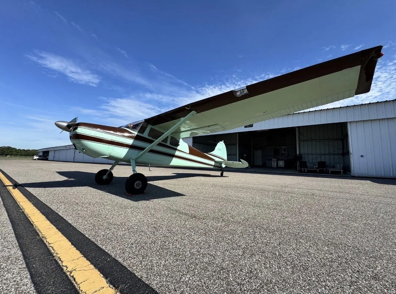
CESSNA 170B · Other Documents
Overview
This issue of Cessna Flyer, published in April 2015, focuses on various topics relevant to Cessna aircraft owners and enthusiasts, particularly the Cessna 170B. It includes articles on engine maintenance, personal flying experiences, and community events. The magazine serves as a resource for pilots looking to enhance their knowledge about aircraft operation, maintenance, and the Cessna flying community. The featured articles provide insights into engine preservation techniques and personal anecdotes from flying experiences, making it a valuable read for both seasoned pilots and newcomers to aviation.
- The Cessna 170B is a classic aircraft that requires dedicated maintenance and care.
- Engine leaning is crucial for optimizing performance; pilots should learn the best practices for their specific aircraft.
- Understanding psychological biases, such as plan continuation bias, can improve safety in aviation.
- Proper engine preservation techniques can extend the life of the aircraft's engine.
Document
Source
Originally published by www.cessnaflyer.org. Sprinkle hosts a reference copy with an added summary, specifications and searchable full text.
Document details
- Type
- Other Documents
- Year
- 2015
- Pages
- 84
- File size
- 18 MB
- Publisher
- www.cessnaflyer.org
Specifications & performance
Extracted from this document.
Specifications
- Range (nm)
- 500
- Engine (hp)
- 145
- Height (ft)
- 8
- Length (ft)
- 24
- Propeller
- McCauley
- Wingspan (ft)
- 36
- Engine model
- Continental O-300
- Max speed (kt)
- 120
- Cruise speed (kt)
- 100
- Empty weight (lb)
- 1,400
- Fuel capacity (gal)
- 40
- Rate of climb (fpm)
- 700
- Service ceiling (ft)
- 12,000
- Max takeoff weight (lb)
- 2,200
Performance
- Fuel burn (gph)
- 10
- Landing over 50ft
- 800
- Max crosswind (kt)
- 15
- Takeoff over 50ft
- 1,200
- Landing distance (ft)
- 600
- Takeoff distance (ft)
- 800
- Best glide speed (kt)
- 65
- Stall speed clean (kt)
- 50
- Stall speed landing (kt)
- 45
V-speeds
- VA
- 100
- VR
- 60
- VX
- 70
- VY
- 75
- VFE
- 85
- VNE
- 150
- VNO
- 125
- VS1
- 50
- VSO
- 45
- VREF
- 60
Weight & balance
- Useful load (lb)
- 800
- Max ramp weight (lb)
- 2,200
- Baggage allowance (lb)
- 200
- Basic empty weight (lb)
- 1,400
- Max landing weight (lb)
- 2,200
- Max takeoff weight (lb)
- 2,200
Common. One of the most common aircraft types we track.
Full essential library on file for the CESSNA 170B.
CESSNA 170B for sale now


Free — save the 170B to your watchlist and track it in one place.
More CESSNA 170Bmanuals & documents
See all 41 →- Dynon Certified SkyView HDX Systems DescriptionSystems Description
- Cessna 170 & C305A (USAF O‐1A) T3 Tailwheel Suspension System Installation InstructionsWeight And Balance
- Instructions for Continued AirworthinessSystems Description
- Service Bulletin: SB-001 Rev CService Bulletins
- Component Maintenance Manual for External Design Wheels ...Maintenance Manual
- Instructions for Continued Airworthiness No. ICA17025Weight And Balance
- Technician’s Service GuideTraining Manual
- Aviation Safety Letter ASL 2/2020Emergency Procedures
- Emergency ProceduresEmergency Procedures
- FAA PARTS MANUFACTURING APPROVALS (PMA) & SUPPLEMENTAL TYPE CERTIFICATE APPROVALS (STC)Supplemental Type Certificate
- Type Acceptance Report TAR 8/21B/24 – Cessna 170 SeriesMaintenance Manual
- FAA Safety BriefingChecklist
If you fly the CESSNA 170B, you may also be researching these.





In this document
The Perfect Plane: Part Two: Our 170B Project is Complete
This article discusses the completion of a restoration project on a Cessna 170B, detailing the challenges and triumphs faced during the process. It highlights the importance of maintaining vintage aircraft and the satisfaction that comes from restoring them to flying condition.
Leaning Lessons: The Science of Operating your Airplane Engine
This section covers the principles of engine leaning, explaining how to optimize engine performance and fuel efficiency during flight. It provides practical tips for pilots on when and how to lean the mixture for various phases of flight.
Plan Continuation Bias: Just Another Name for Get-There-Itis
An insightful article discussing the psychological factors that can affect pilots' decision-making, particularly the tendency to push through adverse conditions to reach a destination. It emphasizes the importance of safety and adhering to personal minimums.
Flying, Interrupted: Modern Engine Preservation
This article focuses on techniques for preserving aircraft engines during periods of inactivity. It provides guidance on proper storage methods and maintenance practices to ensure engine longevity.
Safety notes
- Always adhere to personal minimums and safety protocols when flying in adverse conditions.
Full document text
Engine Essentials: Leaning Lessons Modern Engine Preservation 170B Project -The Perfect Plane VOL 12 ISSUE 04 APR 2015 cessnaflyer.org 42 page PRSRT STD US POSTAGE PAID PERMIT NO 5377 DENVER, CO CHANGE SERVICE REQUESTED CESSNA FLYER ASSOCIATION PO BOX 6203 ALTADENA, CA 91003 CESSNA 172/ 175 FUEL VALVES These premium, high quality PMA’d factory new fuel selector valves replaced Cessna #0513120-5. Complies with AD 99-27-02 at less than HALF the cost of new Cessna valves. P/N 05-11164 ................$1,295.00 Cessna Flyer is the official publication of the Cessna Flyer Association. Cessna Flyer is published monthly by Avia- tion Group Limited, PO Box 6203, Altadena, CA 91003. POSTMASTER: Send address changes to Cessna Flyer, PO Box 6203, Altadena, CA 91003. Subscriptions, advertis- ing orders, and correspondence should be addressed to PO Box 6203, Altadena, CA 91003. Annual dues: $44.00 in the US; Canada and Mexico add $15.00 per year; all others add $25.00 per year (US Dollars only). Eighty per- cent (80%) of annual dues is designated for your magazine subscriptions. The information presented in Cessna Flyer is from many sources for this there can be no warranty or responsibility by the publisher as to accuracy, originality or complete- ness. The magazine is sold with the understanding that the publisher is not engaged in rendering product en- dorsements or providing instruction as a substitute for appropriate training by qualified sources. Cessna Flyer and Aviation Group Limited will not assume responsibility for any actions arising from any information published in Cessna Flyer. We invite comments and welcome any report of inferior products obtained through our advertis- ing, so corrective action may be taken. PO Box 6203 Altadena, CA 91003 Tel: 800.397.3920 www.cessnaflyer.org The Official Magazine of The Cessna Flyer Association PRESIDENT Jennifer Dellenbusch jen@aviationgroupltd.com VICE PRESIDENT / DIRECTOR OF SALES Kent Dellenbusch kent@aviationgroupltd.com MANAGING EDITOR Heather Skumatz heather@aviationgroupltd.com CREATIVE DIRECTOR Yee Chan EDITOR AT LARGE Thomas Block CONTRIBUTING EDITORS Mike Berry • Steve Ells • Lyn Freeman David Hipschman • Michael Leighton Charles Lloyd • John Loughmiller Dan Pimentel • John Ruley • Scott Sherer CONTRIBUTING PHOTOGRAPHERS Paul Bowen • Robb Gessert • Keith Wilson Vol. 12 Issue 04 APRIL 2015 CES SNA F LYE R (04) APRIL 2 015 It’s the number one aftermarket cylInder In the world. MillenniumC y l i n d e r s ® MillenniumC y l i n d e r s ® Millennium Cylinders is a registered trademark of Superior Air Parts, Inc. 3 7 8 4 5 2 1 9 6 The Superior mark signifies the feature is a Superior design or manufacturing innovation. advanced alumInum alloy heads Increased Port wall thIckness comPuter-Generated head fIn confIGuratIon ImProved coolInG very hIGh QualIty castInG throuGh hardened steel barrels ams6382 steel barrels advanced cylInder barrel choke volumetrIcally matched Ports they’re In-stock and ready for delIvery from your nearest mIllennIum cylInder dIstrIbutor 1 2 3 4 5 6 7 8 9 10 10 reasons why more aircraft owners put their trust in Millennium Cylinders. For more information about Millennium Cylinders, please contact an authorized distributor. For a complete list, visit our website or call: +1.800.277.5168 or +1.972.829.4600 superiorairparts.com Subscription and hardware sold separately. Fees and taxes apply. The subscription plan you choose will automatically renew and you will be charged according to your chosen payment method at then-current rates. To cancel you must call us at 1-866-635-2349. See our Customer Agreement for complete terms at www.siriusxm.com. Data displays vary by device; images are representative only. SiriusXM Services may include weather and other content and emergency alert information. Such information and data is not for “safety for life,” but is merely supplemental and advisory in nature, and therefore cannot be relied upon as safety critical in connection with any aircraft, sea craft, automobile, or any other usage. SiriusXM is not responsible for any errors or inaccuracies in the data services or their use. © 2015 Sirius XM Radio Inc. Sirius, XM and all related marks and logos are trademarks of Sirius XM Radio Inc. Apple, the Apple logo and iPad® are trademarks of Apple Inc., registered in the U.S. and other countries. App Store is a service mark of Apple Inc. All other marks, channel names and logos are the property of their respective owners. All rights reserved. Introducing the New SiriusXM® Aviation Receiver. The SXAR1 For the first time ever, pilots using the iPad® can access and view SiriusXM Aviation in-flight weather data delivered via satellite to monitor storm fronts, track lightning strikes, TAFs, METARs, winds and more. Also enjoy SiriusXM Satellite Radio when you add it to your device. WSI’s Pilotbrief Optima™ for iPad – VFR Basemap with Radar, Storm Cell Attributes, and Lightning Layers LEARN MORE AND SEE EXCITING OFFERS AT SIRIUSXM.COM/SXMAVIATION 52 36 56 42 26 The Perfect Plane: Part Two: Our 170B Project is Complete by John Nielsen Leaning Lessons: The Science of Operating your Airplane Engine by Steve Ells Plan Continuation Bias: Just Another Name for Get-There-Itis by Brent Owens Flying, Interrupted: Modern Engine Preservation by Steve Ells Louisiana’s Other Side: Shreveport by Heather Skumatz THE VIEW FROM HERE Jennifer Dellenbusch LETTERS to the EDITOR CESSNA FLYER EVENTS LEFT COAST PILOT John Ruley QUESTIONS & ANSWERS Steve Ells AFFIRMATIVE ATTITUDE Dan Pimentel NEWS ADVERTISER INDEX FLYER’S MARKETPLACE BACK WHEN: VINTAGE CESSNA ADVERTISING AND MARKETING 08 08 10 14 18 22 66 80 81 82 APRIL 2015 Cover: Cessna 170B Photo: John Nielsen Photo: John Nielsen Engines and Events LETTERS to the EDITOR Send your letters to editor@cessnaflyer.org “‘Big Airplane’ Safety: A Cessna 340/340A Buyer’s Guide” by Jerry Temple, March 2015 Heather, Received the March issue. The 340
Show full textShow less
article was well produced. Jerry Temple Frisco, Tex. “Old Notes, Part Two” Full Circle by Thomas Block, March 2015 Dear Editor, Tom’s March article is GREAT. I think one of his best, ever. Thanks, Tom. Jan Randle Hickory, N.C. Welcome to the club Dear editor, The March issue of Cessna Flyer was the first one I received after I joined several weeks ago, and I found many things to like. [You publish] informative columns, the big mix of articles, and lots of friendly help when I called for some parts locating advice. Getting involved in the forum online has been the icing on the cake. So glad you guys are around to support me and my little Cessna that I like to call Freestone. John C. Downey Marietta, Ga. Correction On the cover of the March issue of Cessna Flyer, the page number for the Cessna 340/340A buyer’s guide article is incorrect. The article begins on page 42, not page 38. In keeping with our promise to provide you with more technical and main- tenance information, this issue of the magazine brings you two articles that focus on aircraft engines. One helps you through the process of “pickling” an engine should you need to store your airplane for a period of time; the other tackles the often-contro- versial subject of leaning. We hope you enjoy them. And speaking of engines, our first confirmed speaker for our 11th Annual Gathering in Waupaca is Keith Chatten, Executive Vice President and General Manager at Superior Air Parts. Chatten is an engineer with extensive experi- ence in General Aviation and he’ll be discussing engine care and maintenance. Other topics tentatively scheduled for this year’s event include avionics, bat- tery care, aviation insurance and 100LL alternatives. We may also be able to offer an FAA approved Wings program as part of our event. Our hotel for the event is Comfort Suites Foxfire, with a rate of just $99/ night for attendees of the Waupaca Gathering. (Hotel information is below. Please also see our ad on page 16 for more information.) We’ll kick off the event on July 18 with a cocktail reception Saturday eve- ning at 6:00 p.m. (location to be determined). Sunday seminars run from 8:30 a.m. to 4:30 p.m. with lunch (included) from noon to 2:00 p.m. Sunday night’s banquet will be held at the Waupaca Ale House. Monday and Tuesday, Gathering attendees will be shuttled to the AirVenture grounds in style via our chartered luxury motor coach. The price is just $75/person for all this. Space on the motor coach is limited, so don’t delay—register today. You can find the event information and register online at CessnaFlyer. org/2015gathering. This page will be updated as additional speakers are con- firmed. You can also call us at 800-397-3920 to register and reserve your space. We always have a great time at the Gathering and hope you’ll be able to join us this year. Blue skies, Hotel Information: Comfort Suites Foxfire 199 Foxfire Drive Waupaca, WI 54981 Telephone: 715-942-0500 Jennifer Dellenbusch THE VIEW FROM HERE CES SNA F LYE R (08) APRIL 2 015 CES SNA F LYE R (10) APRIL 2 015 come early for a seat. For more informa- tion, visit oshbash.com. Oct 15 – 17 — Palm Springs, CA. Flying Aviation Expo. A world-class weekend of seminars and workshops, outdoor displays, indoor exhibits—and even an aircraft parade. Thousands of pilots and industry experts from around the world are expected to attend. Learn about new prod- ucts, receive technical advice and partici- pate in hands-on demonstrations. For more information, visit aviation-xpo.com. FEATURED EVENTS April 15 – 18 — Friedrichshafen, Germa- ny. AERO Friedrichshafen 2015. AERO Friedrichshafen is the premier European trade show for the General Aviation in- dustry, which occurs every year in the sce- nic city of the Zeppelins: Friedrichshafen, Germany. Situated in Central Europe within the three-border-triangle of Swit- zerland, Austria and Germany, AERO is the ideal platform to enter the European market for General Aviation. Organized by Messe Friedrichshafen GmbH. For more information, visit aero-expo.com. April 21 – 26 — Lakeland, FL. Lakeland Linder Regional (KLAL). 41st An- nual Sun ‘n Fun International Fly-in and Expo. Meet aviation enthusiasts from around the globe and enjoy one of the world’s greatest aviation conventions. This six-day event celebrates aviation with thousands of airplanes, hundreds of commercial exhibitors and educational forums, seminars and hands-on work- shops for virtually every aviation interest, plus a midweek twilight illuminated airshow and Saturday spectacular includ- ing fireworks. For more information, visit sun-n-fun.org. CFA EVENTS Jul 18–19, 2015 — Waupaca, WI. Waupa- ca Municipal (KPCZ). The 11th Annual Gathering in Waupaca. Saturday night cocktail reception, Sunday seminars, lunch and banquet. $75/person. Space is limited; sign up now. Call 800-397-3920, email kent@aviationgroupltd.com or visit CessnaFlyer.org. CFA SPONSORED EVENTS July 21 — Oshkosh, WI. Affirmative At- titude LIVE! Join Cessna Flyer columnist and Airplanista blogger Dan Pimentel from 5:30 to 7:30 pm as he hosts some very special guests: the impressive movers and shakers you’ve been reading about in the Affirmative Attitude column. Space is limited for this event held in the press tent on the EAA AirVenture grounds; SEND EVENTS to editor@cessnaflyer.org May 2 — Peachtree City, GA. Aircraft Spruce East Customer Appreciation Day. 8 am to 4 pm at Aircraft Spruce & Specialty Co. East, 452 Dividend Drive in Peachtree City, Ga. This is the time of year when Aircraft Spruce goes all out! We’ll have spectacular discounts on our most popular products. The event gives our loyal customers a chance to meet our vendors, too. For more information, call 770-487-2310 or 800-831-2949. May 2-3 — Anchorage, AK. Ted Stevens Anchorage International Airport (PANC), FedEx Hangar. 18th Annual Great Alaska Aviation Gathering. Come to an Alaskan aviation adventure under the midnight sun presented by the Alaska Airmen’s Association. This premier aviation event is a must-see for all ages with inside and outside static displays, a safety confer- ence and much more. Over 23,000 pilots and aviation enthusiasts are expected to attend. Free admission. For information, visit greatalaskaaviationgathering.org. May 8-10 — Valdez, AK. Valdez Pioneer Field Airport (PAVD). 12th Annual Valdez Fly-in and Air Show. This three-day event attracts thousands of spectators and hun- dreds of pilots from all over Alaska, the Lower 48 and other countries. This true family/spectator event features include a unique Poker Run Beach Landing; STOL competition (various aircraft classes); flour bombing competition; aerobatics; skydivers; static displays and a kids’ balsa plane event; plus seminars and round-table discussions for pilots. A variety of vendors also attend. For more information, visit valdezflyin.com or call 907-835-8244. OTHER EVENTS Apr 18 — Independence, IA. Indepen- dence Municipal (KIIB). Tailwheel Fly-in. Start the year off right by attending our 1st annual Tailwheel Fly-in Breakfast! All aircraft, friends and family are welcome to attend. Breakfast will be served from 8 to 11 am. At 10 am, there will be a safety seminar in the upstairs conference room of the main terminal hosted by Jonathan Walter. Walter will discuss the sticky points of tailwheel flying. FAAST Wings credit is available. Awards will be given for Oldest Tailwheel Aircraft and Classiest Tailwheel (no black ties needed!). Discounted fuel prices during the event. For more informa- tion or to RSVP, call 319-334-4000. Visit walteraviation.com/#!events/c5k2. Apr 18 — Camarillo, CA. Camarillo Air- port (KCMA). “Art & Science of Flying” Ground School with Rich Stowell. A VC99s pilot proficiency class. This interactive ground school weaves history, biology and technology into a high-level explora- tion of the wonder of flight in general and of airplane and human performance in particular. There is a $65 fee for this class; preregister at least 24 hours in advance at vc99sclasses.com. Contact Carolyn Brown, 805-910-6894 or email classes@vc99s.com. Apr 18 — Cookson, OK. Tenkiller Airpark (44M). 26th Annual Wild Onion & Eggs Breakfast Fly-in. 8 to 10:30 am. Best breakfast in Oklahoma. Cost is your donation. Fly-in camping available with showers in the FBO. Fuel available for cash or check. Contact Val Westedt, 918- 457-4774 or email veedster@aol.com. Apr 18–May 4 — Mocksville, N.C. Sugar Valley Airport (5NC2). Camp on your way to/from Sun ‘n Fun. Sugar Valley Airport has private paved and turf landing strips and is an ideal location for camping by the 17-acre lake on the field. There is a small bath house not far from the camping area. EVENTS continued on page 78... 1-800-647-6148 • www.ffcfuelcells.com All FFC fuel bladders are manufactured with REGISTERED TSO-C80 constructions... KNOW what you are installing. Quality products at competitive prices. TSO-C80 FUEL CELLS CES SNA F LYE R (12) APRIL 2 015 www.wipaire.com Wipline Floats ∙ Aircraft Skis ∙ Modifications South St. Paul, Minnesota 651.451.1205 352.323.4809 55th Anniversary • 1960 - 2015 Leesburg, Florida AVIONICS by Wipaire Interiors ∙ Maintenance ∙ Paint ∙ Aircraft Sales Get ADS-B ready with avionics from Wipaire’s expert team! Call today to discuss options for complying with the 2020 mandate. Visit Us at Sun ‘n Fun (Booth MD-003D) and register to win a Bose A20 headset! goes wrong. If something does go wrong, with widespread fog and low ceilings, where can you go? I did a Google search and found some really interesting discussions connected to old magazine articles on departure minimums. Then I picked up the phone and talked the whole subject over with my good friend and longtime flight instructor Larry Askew. I finally decided that my personal departure minimums are basically the same as commercial pilots use: at least one mile visibility and a 500-foot ceiling. That’s enough that you’d have a fighting chance to live through an engine failure on takeoff. Fortunately on our departure day, the weather cooperated and the fog lifted by noon. We had a great ride down with a 20-knot tailwind. I was a little nervous as there were multiple AIRMETs (and even a SIGMET) for severe turbulence mainly over the Sierras, but all we got was a mild mountain wave after we crossed the first big ridge near the Lake Hughes (LHS) VOR. I had a Stratus ADS-B receiver running, and actually saw a fair amount of traffic from it on my iPad—enough to make me wonder if I may have been seeing the benefit of flying near another airplane equipped with ADS-B Out. I took a few screen grabs, and after looking at those, it was clear we were following a PC-12. Since the tail number showed up, I’m betting the pilot was running an ADS-B compatible Mode S transponder, so ground stations were relaying tran- sponder traffic to him, and while nearby we were picking it up. That illustrates why you need installed ADS-B Out equip- ment (a 1090 MHz Mode S transponder or 978 MHz UAT) to get reliable ADS-B traffic. With just the receiver, you sometimes see traffic and sometimes don’t. I also noticed a few scattered areas of light precipitation— evidently the fog or mist was dense enough to show up on ground-based radar, which is relayed by ADS-B ground stations along with traffic. Usually there are just a couple of minutes in the soup on climbout, and then gorgeous clear air above. No problem at all—provided nothing goes wrong. I have never been a fan of personal minimums—the idea that you should set limits for yourself short of what’s required by the FAA. Particularly for instrument flying, if you aren’t pre- pared to shoot an approach to minimums as specified on the chart, you shouldn’t file, because you’re going to have to deal with whatever weather develops. That’s one reason for the “1-2-3” rule about specifying an alternate if the weather isn’t forecast to have at least a 2,000- foot ceiling and three miles visibility for one hour before and after your planned time of arrival. But I’ve had a change of heart, at least in one respect: I’ve now set personal minimums for visibility and ceiling when departing on an IFR flight. That came about as a result of planning for a flight to Los Angeles with my wife during the fog season. We were in a relatively wet winter season here in California’s Central Valley, which makes fog common. When there’s no frontal weather, radiation fog is common most mornings and indeed sometimes builds up to persistent tule fog that can cover fairly large areas. Most of the time, the fog will burn off as the sun comes up, but deep in the winter you get a condition where the fog never completely burns off—it just rises into a low stratus, then settles back on the ground at night. Periodically, a weather system moves through and disrupts the stable pattern, but between those systems, morning fog is the rule here until spring. It’s just something we learn to live with, and one of the reasons that an instrument rating really helps. That had been happening the week before we were due for our trip: on Thursday, visibility stayed at one-quarter of a mile with an indefinite ceiling at about 100 feet until about 4:00 p.m.—and even after that, never got better than half a mile. That caused me to do some hard thinking. For noncommercial flights conducted under Part 91, there are no minimum visibility or ceiling requirements for instrument departures; if you can see to taxi your airplane, you can get a clearance (which may include the highly significant words “at your own risk”) and take off. I’ve never been fool enough to do that, but up to now, my departure minimums were basically the instrument minimums to get back into the airport. At my home base of Modesto, Calif. (KMOD), that’s one-half mile visibility and a 200-foot ceiling for the ILS approach. What got me to thinking, though, was that the fog was so widespread. The whole valley was socked in. I have flown in these conditions before, and usually there are just a couple of minutes in the soup on climbout, and then gorgeous clear air above. No problem at all—provided nothing Personal Minimums and the Fog Season Widespread fog prompts a change of heart about personal minimums on departure. John Ruley LEFT COAST PILOT John Ruley LEFT COAST PILOT CES SNA F LYE R (14) APRIL 2 015 It’s a computer. It still works. Don’t be this guy. It’s time to upgrade. Your old GNS530 can be traded up to the Plug & Play IFD540 for less than you think! Flying Made Simple ™ IFD540 FMS/GPS/NAV/COM Plug & Play for GNS530! Call Brian for a value estimate 781-402-7520 The 11th Annual Gathering at Waupaca A full slate of seminars and workshops; a Sunday evening banquet and many other opportunities for socializing; raffle prizes; and two days of luxury motor coach transportation to AirVenture For more information or to register, visit CessnaFlyer.org/Waupaca or phone 800-397-3920 Make your hotel reservations now at Comfort Suites Foxfire in Waupaca by calling 715-942-0500 Space is limited, so sign up today! Participate in informative seminars with industry leaders. Participate in informative seminars with industry leaders. Participate in informative seminars with industry leaders. Fly in to beautiful Waupaca (KPCZ). Enjoy an evening banquet and socialize with your CFA friends. Enjoy an evening banquet and socialize with your CFA friends. Join us for our pre-OSH event July 18 & 19, 2015 Two days of luxury motor coach transportation to EAA AirVenture is also included. The only problem with the flight was that we’d gotten out about half an hour late, so we arrived just at dusk—which put the sun in my face on our long straight-in approach to Hawthorne (KHHR) Runway 25. I was almost blinded and got on the gauges, telling Kate to look for traffic. Fortunately the sun went down when I was still joining the localizer, which let me flare without squinting. One odd thing: the final approach controller announced, “Cleared into Class B airspace via the Hawthorne 25 localizer; report the airport in sight”—which was ridiculous as I’d been in the Class B airspace for a good 10 minutes at that point. I replied that I was IFR. He cleared me for the visual approach. Two days later, I again had to wait for the fog to start lifting before departing for home. I also decided to fly a slightly differ- ent route: instead of directly over the mountains into the valley, I planned to fly up the coast, turning inland at Morro Bay. The MEAs for the route were all 8,000 feet or less, which eliminated any need to use oxygen. The route is also a bit pret- tier and kept us away from the fog as long as possible. However, the route that I filed was pretty complex: KHHR HERMO V23 LAX SMO V107 SADDE V299 VTU V25 RZS V12 GVO V27 MQO V113 PRB V113 ROM V113 PXN KMOD 13GPH 8000FT The routing was complicated enough that I saved it to Notes on the iPad, and hand-wrote it on my clearance pad. When I called for my clearance, I received this: “Cleared to Modesto via left turn heading 210; radar vectors Ventura [VTU]; then as filed. Climb and maintain 3,000. Expect 8,000 in five minutes…” and the usual departure control and squawk. ATC’s vectors were pretty close to what I asked for, except that it didn’t hug the coast quite as much, and probably put us four to five miles out over the water, but by that time we were at 6,000 feet, so I was still comfortable. It was a pretty flight with no turbulence at all, and no more than a 15-knot headwind. Turning inland we could see low stratus and heavy haze filling the valley. Modesto was reporting four miles and clear below 12,000 feet, but I asked for and flew a full ILS and was on the gauges from about 1,500 feet. I still don’t believe in setting arrival minimums higher than those for the best available instrument approach. If I’m not up to flying a full ILS, I need to get more practice. But taking off into widespread low fog strikes me as an unnecessary risk. I’ll add that when I’m planning a flight into an area with widespread fog, I pay a lot of attention to the local weather trend and get very serious with my alternate planning. There’s no sense taking off until—and unless—the trend is improving; otherwise you run the risk of being unable to get in, and if that’s a serious risk, then I want an alternate that’s CAVU. Fortunately, in N4696K we have long-range fuel tanks, so I usually have a lot of good options. John D. Ruley is an instrument-rated pilot and freelance writer. He holds a master’s degree from the University of North Dakota Space Studies program (space.edu). He is a volunteer with ligainternational.org and angelflight.org, two charities which operate medical missions in northwest Mexico and provide medical patient transport, respectively. Send questions or comments to editor@cessnaflyer.org. Flying Made Simple ™ IFD540 FMS/GPS/NAV/COM Built for Speed. www.IFD540.com "Going fast is my business. That’s why I chose Avidyne’s IFD540 for my GPS/NAV/COM upgrade. The direct replacement of my old 530 took no time at all, and entering flightplans is fast and easy." Bill Elliott IFD540 Customer NASCAR ® Legend Call Brian for more info 781-402-7520 CES SNA F LYE R (17) APRIL 2 015 CES SNA F LYE R (18) APRIL 2 015 Steve Ells QUESTIONS & ANSWERS Owner-produced parts and Cessna product improvements After the outside diameter has been determined, the length of 4130 tubing and the fitting can be purchased from any number of aircraft parts vendors. After the parts come in, clean off the surface anodized layer on the AN fitting, remove any oil off the tube, and cut the tube length to match the length on your existing part. Braze the tube to the fitting, and ta-da! An owner-produced aircraft part. Happy flying. Dear Steve, My father’s cousin wants me to buy what he says is his “real nice” 1974 Cessna 210L. I’ve ridden in his 210 and was impressed. The biggest problem I can foresee is that he’s a notorious cheapskate. I don’t mean that he neglects basic maintenance like regular oil changes, but I worry a little bit about product upgrades—if there are such things for airplanes. Are there upgrades? And can you give me an example of one? —Hopeful Hank Dear Hank, One of the best tools available from Cessna is its Continuous Airworthiness Program (CAP) document. It’s a list of items that Cessna has compiled to maintain aircraft in the field. The CAP document for this 210 is CAP 200 D5121-1-13, and the cost is just over $50. If I were negotiating with my father’s cousin over the purchase of his “real nice” 210, it’s the one document I would want to use in determining the condi- tion of the airframe. Cessna produces upgrades for every model they make in the form of Service Letters, Service Instructions and Service Bulletins. Cessna issued over 400 of these service publications that may apply to the 210 between Jan. 1, 1970 and today. Many are informational (Wichita is now a U.S. port of entry, etc.); many are generic in nature and apply to every Cessna model (new techniques in corrosion protection, prevention and removal); and many are safety upgrades that are applicable across the entire Cessna line, such as the ones that are issued in conjunction with a government-mandated change called an Airworthiness Directive. Cessna provides guidance about com- pliance by labeling each of these publications “informational,” “recommended,” “optional” or “mandatory.” Hi Steve, I sent you a picture of a part I need for my Cessna 182 (photo, right). This part screws into the intake manifold above the carbure- tor. The hose for the manifold pres- sure gauge screws onto the part. My mechanic told me I need to change it, but I haven’t been able to find the part number in my Cessna 182 parts manual. Can you help? —Brad Robinson Dear Brad, The part you’re looking for is called an adapter assembly and the Cessna part number is 0750282-1. That’s the part number for the item that connects the manifold pressure line to the engine according to the 1962-73 Cessna 182 parts manual. The list price for the part is over $400, although you may be able to get a used one from an airplane salvage company such as CFA supporters Wentworth, Dodson and Preferred Airparts; White Industries, Texas Air Salvage and others may also have it. KRN Aviation Services shows three on hand, according to its website. The part appears to be a standard AN flared tube-to-pipe thread aircraft part that has a short steel tube brazed on the pipe thread end. The only reason for the short length of tubing is to keep any fuel that’s condensed on the walls of the mani- fold from running down into the manifold pressure line. Since the list price seems out of line for one fitting, you, as the owner, can look into the option of manufacturing a replace- ment fitting under the owner produced parts rule of the FARs. Some guidance for owner produced parts is can be found in the following Advisory Circulars: AC 20-62E, “Eligibility, Quality and Identification of Aeronautical Replacement Parts”; AC 43-213A, “Parts Marking Identification”; and AC 43-18, “Fabrication of Aircraft Parts by Maintenance Personnel.” Since it appears from the photo you sent that the only thing wrong with the adapter is the misshapen wrenching section, you can use your “bad” part as data to fabricate a new one. I’d recommend that you run this idea past your mechanic before you spend too much time on it—you’ll want to ensure he’s amenable to installing the part after you’ve fabricated it. From the photos, it looks like you’ll need an AN816-4-4 fit- ting and a short length of one-quarter inch (outside diameter, or OD) thin wall 4130 chromium-molybdenum alloy (chromoly) steel tubing to fabricate one of these. Measure the tubing OD to make sure. Cessna issued over 400 service publications that may apply to the 210 between Jan. 1, 1970 and today, and some address new techniques in corrosion protection, prevention and removal. This photo shows corrosion penetrating the skin of a 210 trim tab. avemco.com/CessnaFlyer *Not all coverages or products may be available in all jurisdictions. The description of coverage in these pages is for information purposes only. Actual coverages will vary based on local law requirements and the terms and conditions of the policy issued. The information described herein does not amend, or otherwise affect, the terms and conditions of any insurance policy issued by Avemco. In the event that a policy is inconsistent with the information described herein, the language of the policy will take precedence. Free hat offer not available in New Mexico. When you call Avemco Insurance Company, you know who answers the phone? An Avemco® Aviation Insurance Specialist at our home office in Frederick, Maryland. Somebody who knows a 180 from a 182. Somebody empowered to make decisions, solve problems and customize a policy based on what you fly and how you fly it. And, if you ever have a claim, Avemco can help you get back in the air fairly and quickly. Because we don’t simply insure Cessnas, we insure the people who love them. A subsidiary of HCC Insurance Holdings, Inc. ADS0126 (11/13) WE TREAT CESSNA OWNERS LIKE A NAME, NOT AN N NUMBER. Call (800) 822 9123 or visit avemco.com/CessnaFlyer Get a personalized quote and get a free hat. SEB00-10 calls for an inspection of welds in the reinforcements that strengthen the pivot fittings at the aft stabilizer spar. Here you can see a crack in the reinforcement. CES SNA F LYE R (20) APRIL 2 015 continued on pg 76... the foam trapped moisture against the inner skins of these critical surfaces. The result is corrosion that can only be detected after it compromises skin thickness. The weight of the moisture also causes control surface imbalance. The only way to guarantee air- worthiness is to install a new trim tab and elevator trailing edges. Cessna has issued many product improvements on its air- planes over the years. Some are critical for safety and continued airworthiness. I’ve provided these examples in hopes that they will convince you to take this “real nice” airplane to an A&P mechanic for a thorough pre-purchase inspection. In fact, since you admit that your father’s cousin is a cheap- skate, I wouldn’t agree to buy it until it has been through a full annual inspection. This might cause some family friction—but you won’t end up throwing good money after bad since you’ll know the true value of the airplane before you buy. Happy buying. As a side note, many maintenance tips and hints are pub- lished in Service Information Letters. Examples include “Nose Wheel Shimmy Troubleshooting” and “Instrument Light Dimming Circuit Troubleshooting.” Some Service Bulletin listings also include a Service Kit (SK) listing. SKs are kits of parts needed to complete the upgrade called out in the bulletin. For instance, there are a number of important upgrades on the tail of the 1974 Cessna 210. One is listed in SEB00-10. It calls for an inspection for welds in the left and right reinforce- ments that strengthen the pivot fittings at the aft stabilizer spar. Another is SEB00-6, which calls for reinforcing the bond of the elevator trim tab skin to the spar by the installation of rivets. Service Newsletter 87-18 revision 1 notifies owners and maintenance that there are now thicker nose ribs available for the horizontal stabilizer. These ribs are often damaged when the leading edge of the horizontal stabilizer is pushed on to move the airplane (or sat on!). SEB88-03 details the procedure to install stronger attach points on a fuselage bulkhead, and also details the proce- dure to install stronger attachment fittings on the front spar of the horizontal stabilizer that is bolted to the bulkhead. Service kits SK210-125 and SK210-126 apply. The combined cost of these two kits is approximately $1,700—installation costs not included. Finally, in 2013 Cessna issued revision 3 on SEB85-7 that called for a detailed inspection of the elevator and trim tab for evidence of corrosion. In lieu of installing and riveting in strengthening ribs, Cessna filled the trim tab and a portion of each elevator with a rigid foam material. This didn’t quite work out as well as planned, since voids in Trade your chocks for S T A R T I N G B L O C K S . U. S . + 1 . 8 4 4 . 4 4 .T X TAV | I N T E R N AT I O N A L + 1 . 3 1 6 . 5 1 7. 8 2 7 0 © 2015 Cessna Aircraft Company. All rights reserved. TTx is a trademark of Textron Innovations Inc., used by permission. Garmin and G2000 are trademarks of Garmin International or associate companies. CESSNA TTx CESSNA TTx This beautiful sprinter was born with the heart of a racer. A twin-turbocharged racing powerplant that speeds the TTx™ to the top of its class at 235 knots. Elegant gull - wing doors float up to reveal sleek, custom cabin schemes and a Garmin® G2000™ flight deck. The all-composite airframe makes it tough enough for Utility Category certification. There’s also an economy cruise setting – but – really? On your mark. Get set. Go to Cessna.com to catch the TTx. Mike Pungercar (below, in the red hat) enjoys the company of all of the World War II veterans on an Honor Flight. Those who served with the Air Force hold a special place in his heart. making contacts around the state, and ended up forming the South Willamette Valley Honor Flight hub in March 2012.” Today, if you see Pungercar working with a sense of urgency, there is a very good reason. “The Greatest Generation,” as they are frequently called, are not getting any younger. Several hundred World War II veterans die every day. The work of flying veterans to Washington to see the memorials is hard, and the hours are long. For each Honor Flight, Pungercar and his team of other volunteers start working six to seven months in advance. Along with negotiating the best possible rates with Southwest Airlines, securing about 100 round-trip tickets and arranging ground transportation, the team also obtains hotel rooms in the departure city of Portland, Ore., and rooms in Dulles, Va. The sky is filled with aviators doing great things with their airplanes, advocating for General Aviation and volunteering to give back to a community that has given them so much. In my quest to seek out subjects for this column, I occasionally find a person who is doing something extraordinary to help others while not flying an airplane to accomplish the task. This month, I’m going a bit off-script in order to bring attention to someone who is doing incredible work to honor veterans of World War II, among them military pilots who flew in the United States Army Air Forces and with the U.S. Navy in the Pacific Theater of Operations. Mike Pungercar, director of South Willamette Valley Honor Flight in Springfield, Ore., is not a pilot—but his father was a radio operator on B-17s during World War II, so Pungercar grew up with a great deal of respect for military airplanes and the brave flyers who rode them into battle. “The Honor Flight Network’s mission,” Pungercar said, “is to get our country’s senior veterans to Washington D.C. free of charge to receive recognition and thank them for their service. Priority is given to World War II veterans, then to Korean War veterans, and then to Vietnam War veterans. We take any terminally ill veterans on the next available Honor Flight. “Most of these aging veterans never received any thanks for their service 60 to 70 years ago,” Pungercar continued. “Our time to honor our World War II veterans is running short.” “Among the 251 World War II veterans who have gone on our Honor Flights are pilots who flew in both Europe and the Pacific. Other veterans who have gone with us served on bomber crews and as ground crew personnel,” Pungercar explained. “Aside from the World War II Memorial, most of these veterans will always remember their visit to the Air Force Memorial in Arlington, Va. “I enjoy the company of all of our World War II veterans on an Honor Flight, but those who flew for and served with the Air Force hold a special place in my heart.” Pungercar’s work as director for his Honor Flight hub in Oregon began during his research on “The Promise Kept,” his 2011 book describing what the men who flew in bombers high above the German battlefield had really experienced. “While working on the book,” Pungercar explained, “I met a World War II veteran in Wisconsin who shared his experience on an Honor Flight; my aha moment came when I was introduced to Bob Maxwell, a World War II Army communications [specialist] and recipient of the Medal of Honor. “After spending time with Bob, and having met other World War II veterans during my book research, I decided to get involved with the Honor Flight program and try to honor as many of these veterans as I could. In November 2011 I started A Part of Our History That Must Never Be Forgotten Book research inspired Mike Pungercar to organize the South Willamette Valley Honor Flight hub. David Hipschman HEADING BUG Dan Pimentel AFFIRMATIVE ATTITUDE For each Honor Flight, Pungercar and his team of other volunteers start working six to seven months in advance. There is a very, very long list of behind-the-scenes work that is completed before the flight ever departs. CES SNA F LYE R (22) APRIL 2 015 The KMA 30 Bluetooth Audio Panel, KSN 770 WAAS- Enabled GPS/Nav Com and the KT 74 ADS-B-ready Mode S Transponder deliver modern air-transport grade functionality at a price that you can afford. And best of all, the BendixKing Trade-Up program allows you to cash in on the value of your older BendixKing avionics to help offset the cost of your retrofit. Plot your course to the future and great value. Contact your BendixKing dealer to find out more about the all new BendixKing avionics and your Trade-Up options. The BendixKing avionics stack delivers today’s best technology without costing a premium. BendixKing.com PUTTING YOU ON COURSE TO GREAT VALUE. TRADE↑UP Qualifying products include KMA 30 Bluetooth Audio Panel, KSN 770 WAAS-Enabled GPS/Nav Com and the KT 74 ADS-B-ready Mode S Transponder continued on page 77... The Global Show for General Aviation EDNY: N 47 40.3 E 009 30.7 April 15 – 18, 2015 Messe Friedrichshafen, Germany www.aero-expo.com Gold-Sponsor: • more than 600 exhibitors from 35 nations • 33.400 visitors, 63 percent of whom holding a pilot license • over 100 AERO Conferences #1 for Aircraft Parts Support Since 1984 Same-Day Worldwide Shipping We Price Match! Parts avionics EnginEs ProPs Over 5 MilliOn in-StOck PartS! Over 5 MilliOn in-StOck PartS! Search our Parts for Free 24/7 DoDSon.coM cAll uS toDAy At 785-878-8000 CES SNA F LYE R (24) APRIL 2 015 In addition, there is a very, very long list of behind-the-scenes work that is completed before the flight ever departs. “We first phone veterans on our waiting list to fill openings on the flight and arrange for their guardians to help with pushing wheelchairs and help them with their medications,” Pungercar said. “There are many details that go into a flight, like lining up 500 bottles of water and contacting our local congressional representatives so we can present United States flags flown over the Capitol in D.C. to each veteran. “We also furnish every vet and guardian with our hub’s Honor Flight shirt; lanyards from Navy, Army, Air Force, Coast Guard and Marine Corps recruiting offices (for our name tags); and [supply] ball caps for each veteran identifying them as a World War II or Korean War veteran.” A major part of the planning for each flight is to make reservations for viewing the Changing of the Guard at the Tomb of the Unknowns in Arlington National Cemetery. This requires bus passes and making reservations, if possible, for representatives from the group to participate in a wreath laying ceremony at the Tomb. For anyone who has flown commercially in a post-9/11 world, you know the drill regarding security, but you may not know that these Honor Flights get a little help from TSA at the departure airport. “At PDX,” Pungercar explained, “TSA personnel escort us to the security screening area and open at least one separate line for our group. With 25 to 30 wheelchairs and walkers typically in use [and] senior citizens with metal implants—some still carrying shrapnel from 70 years back—screening is a slow but steady process.” If this all sounds like a lot of work, it is. But the rewards for those who make it happen are priceless, said Pungercar. “On the first Honor Flight I led, we were at the Tomb of the Unknowns and had witnessed the Changing of the Guard and a wreath laying ceremony. “I looked around at the veterans as ‘Taps’ was being played. Most had removed their hats and were standing or sitting erect and saluting—and, like me, had tears in their eyes. I knew in my heart that what I was doing was making a difference for these men and women who—like my dad—had helped save our country with their service in World War II. “If you’re at 65 percent of power or so, 50 degrees rich of peak probably won’t get you in trouble, and will give you close to maximum power for that manifold pressure and rpm. But the fact is that 50 degrees rich of peak will produce the absolute hottest possible temperatures for all parts of the engine.” John Deakin Advanced Pilot Seminars By Steve Ells CES SNA F LYE R (26) APRIL 2 015 Leaning Lessons: The Science of Operating your Airplane Engine Learn to ignore EGT numbers; you’re looking for the first one to peak, not the one with the hottest EGT number. The MVP-50 from Electronics International allows pilots to accurately monitor dozens of engine and system parameters, program redline limits, and much more. Prior to my first cross-country flight from Seattle (KBFI) to Arlington, Wash. (KAWO), I was told that we were going to lean the engine when we got up to cruise altitude. I was instructed to pull the mixture knob slowly aft until the engine started to get rough, then to push it back in until the engine smoothed out. Since those early days I’ve learned quite a bit more about leaning. The following is a general discussion on the basics of lean- ing; it is intended only to be educational. Always refer to your Flight Manual or POH for specific leaning instructions. Red knob basics Leaning seems simple: since air density decreases as air temperature and alti- tude increases, and since the carburetors and fuel injection components on our airplane engines don’t adjust for these density changes, pilots need to manu- ally reduce the amount of fuel delivered to the engine combustion chambers to maintain the most efficient and economi- cal fuel /air ratio. Pilots sometimes hear opinions that leaning burns exhaust valves, and that fuel is less costly than a top overhaul. Based on these convictions they may conclude that leaning is bad. However, real-world testing of engines—in what’s probably the world’s most sophisticated aircraft engine test cell—have proven those claims to be false. The main reason you should learn to lean correctly is to maintain the health of your engine. A second reason is to save money. An airplane engine can be leaned whenever it’s running. All engines can be safely leaned during taxi—in fact, it’s a good practice to lean during taxi to cut down on the possibility of spark plug fouling due to carbon or lead contamina- tion. Just remember to always richen the mixture to adjust for the airport density altitude before turning onto the runway for takeoff. A rich mixture means there’s a surplus of fuel compared to the amount of air. This excess fuel slows combustion. Excess fuel is also detrimental to long-term engine health for at least two reasons. Carbon cre- ated during incomplete combustion, along with tetraethyl lead (TEL), a fuel additive that reduces the possibility of uncontrolled combustion (detonation), is deposited on valve stems, piston crowns and piston ring lands. A richer than necessary mixture wastes fuel and has the long-term effect of lessening engine efficiency. Landmarks on the mixture map As can be seen in “Landmarks on the Way to Understanding Piston Engine Powerplant Management” illustration (photo 01, page 28), as the red knob is pulled aft (leaned), every important engine parameter—except fuel consump- tion—initially rises. CHT, EGT, internal combustion pres- sures (ICP) and horsepower (HP) all increase predictably; then they decrease predictably. These landmarks are true for every piston aircraft engine in the fleet. Only brake-specific fuel consumption (BSFC) decreases. BSFC is a meaningful number depicting the number of pounds of fuel burned per hour for each horse- power produced at the propeller shaft (Lb/BHP/Hr). This number for aircraft reciprocating engines varies between 0.35 and 0.6 depending on the engine specifications, atmospheric conditions and leaning practices. Peak EGT is the zero point milepost for all leaning. It’s where all the fuel mol- ecules and all the oxygen molecules are consumed in combustion. It takes approximately 15 pounds of air and one pound of fuel for complete combustion. It’s called peak EGT because this fuel-to-air ratio produces the hottest combustion temperature. On the rich side of peak EGT, excess fuel slows and cools combustion; on the lean side of peak EGT, a deficit of fuel slows and cools combustion. When the mixture is leaned beyond peak EGT, all the landmarks begin to decrease. It makes sense: as the amount of fuel in the fuel/air mixture decreases, so does the amount of heat energy created during combustion. Leaning beyond peak EGT is referred to as running lean of peak (LOP). Operating LOP dramatically reduces carbon and TEL deposits in high tem- perature parts of the engine such as the exhaust valve stem, the piston crown and the combustion chamber. LOP operations are much “cleaner” and also dramatically reduce the amount of carbon monoxide in the exhaust stream. There are two vertical dashed lines on the roadmap. The one to the left side of the peak EGT dotted line indicates a mixture that is 50 degrees rich of peak, or ROP. The dashed line to the right of the peak EGT line indicates a mixture that is 50 degrees LOP. (For readers’ ease, all references to degrees in this arti- cle are in Fahrenheit (F) unless otherwise marked. —Ed.) The CHT and ICP lines are relatively flat from approximately 80 degrees ROP to just before peak, then both begin to drop off; the HP line rises and peaks between 80 degrees and 50 degrees ROP and then drops off; while the fuel con- sumption (1/BSFC) “peaks”—if you will— between peak EGT and 50 degrees LOP. Referring again to the roadmap, notice that only EGT is equal at the Rich and Lean dashed lines; CHT, EGT, ICP, and HP are all lower on the lean side. BSFC is at its maximum on the lean side. As a number, peak EGT has zero value to the pilot since variables such as the positioning of the probe in the exhaust tube and distance from the cylinder exhaust port affect this number. Yet, no matter what the number, peak EGT is the critical reference point when leaning. Peak EGT is the first signpost. This critical leaning signpost is always defined by the first cylinder to peak; that’s the leanest cylinder in the engine at that fuel/ air ratio. Learn to ignore EGT numbers; you’re looking for the first one to peak, not the one with the hottest EGT number. Important definitions Remember these two definitions. Best Power is the fuel/air ratio at which the Best Power is on the rich side of peak EGT; Best Economy is on the lean side. CES SNA F LYE R (28) APRIL 2 015 PHOTO 01 This illustration shows that as the red knob is pulled aft (leaned), every important engine parameter—except fuel consumption—initially rises. CHT, EGT, internal combustion pres- sures (ICP) and horsepower (HP) all increase predictably; then they decrease predictably. These land- marks are true for every piston air- craft engine in the fleet. According to Brian Wrightman at Insight, lean of peak opera- tion in the “best economy” range as shown on this Cruise Power Settings table is permitted on many models and should be used primarily for trips where extended range is desired. Lean of peak operation requires the operator to monitor EGT close- ly, as power and temperature may change rapidly in response to small changes in fuel mixture. Table: Insight Instrument Corp. This diagram of the readings on Insight’s G4 engine monitor (shown here for six-cylinder twin aircraft) illustrates its many features as well as how the Select button can be used to adjust for LOP and ROP. Photo: Insight Instrument Corp. engine produces maximum power for a fixed mass of airflow. We have already said best power is obtained at around 80 degrees rich of peak. All GA engines can be leaned to best power. Best Economy is the fuel/air ratio at which the engine produces the maximum power for a fixed mass of fuel flow. At low power (65 to 70 percent, or below) this is 15 to 40 degrees lean of peak. At higher power settings, the point is 40 to 90 degrees rich of peak. A great many GA engines can’t be successfully operated at these Best Economy settings. Best Power is on the rich side of peak EGT; Best Economy is on the lean side. The development and installation of EGT probes—and more recently, very sophis- ticated engine monitors—have provided pilots with tools that simplify leaning. Fixed pitch propeller, no EGT instrument One leaning tool for a “no-instrument” airplane consists of leaning until engine roughness is felt and then richening until the engine smoothes out. Another is lean- ing for the highest airspeed. Since horsepower peaks at approximate- ly 80 degrees ROP, this will also show up as a maximum indicated rpm. Leaning to maximum rpm is difficult with basic instrumentation due to the inherent inac- curacy of an analog tachometer. The drawback of this method is that the CHT and the ICP will be near, or at, the maximum values. Single cylinder or single point (manifold) EGT In the mid-1960s the EGT gauge was introduced to General Aviation by Al Hundere of Alcor Inc. Soon Cessna began to offer EGT gauges as an option. The tool used a single EGT probe that was installed in a single exhaust pipe downstream from a single cylinder, or in an exhaust collector that combined exhaust gases from two or three cylinders. A single EGT probe is better than no EGT indicator in that it gives the pilot a rough idea of peak EGT indication. However, due to something called EGT spread, pilots are often puzzled while leaning to peak with a single-probe sys- tem when the engine starts to feel a little rough before or when the peak EGT is indicated on the gauge. When roughness is felt, that means that the probe is not installed on the first cylin- der (leanest) to peak. Due to EGT spread (which I’ll explain soon) the power out- put across the cylinders is mis-matched; this creates a noticeable vibration. When CES SNA F LYE R (30) APRIL 2 015 PowerFlite® Alternator Approved on Cessna 172R, 172S, 182S, 182T & T182T Direct identical FAA/PMA certified replacement • Identical mounting points and drive pulley • No modification necessary • Lower "Come-In Speed" • Competitive cores accepted • 2 year warranty this occurs, the onset of vibration must be used as the peak EGT point. A single EGT gauge was a big step for- ward in mixture management, but there was still more needed. All-cylinder engine monitors In 1981, John Youngquist of Insight Instrument Corp. expanded our under- standing of leaning when Insight intro- duced a small panel-mounted instrument called the Graphic Engine Monitor (GEM). The GEM showed EGT and CHT for all cylinders in a graphical presentation and instantly revealed a little-known fact to aircraft owners: as pilots leaned the mixtures, no two cylinders peaked at the same point in leaning. In the ideal internal combustion engine, each cylinder generates an identi- cal power pulse. This requires that the fuel/air ratio delivered to each cylinder of an engine be evenly matched—but this ideal is unobtainable in many, if not most piston aircraft engines due to inefficient engine induction systems. EGT spread Six-EGT-displays-in-one instruments revealed a characteristic known as EGT spread. As we learned more about how individual cylinders react when leaning, we realized that leaning to peak EGT by referencing a single EGT probe is a crap- shoot since pilots had no way of know- ing if the single probe is installed on the first cylinder (leanest) to peak. And if the probe isn’t on the first cyl- inder to peak, one or more of the other cylinders could have already peaked and be burning an LOP mixture. While this isn’t harmful to the engine at power lev- els below 60 percent, it results in a less- than-smooth engine. PHOTO 02 The author installed a switchable six-cylinder EGT gauge in his 1966 Cessna 182J, then tried leaning to get all six cylinders LOP. He concluded that it was impossible to operate that carbureted engine LOP since the amount of fuel/air mixture entering the combustion chamber of each cylinder varied widely. The EGT spread was often 150 degrees. CES SNA F LYE R (31) APRIL 2 015 CES SNA F LYE R (32) APRIL 2 015 PHOTO 03 GAMI has developed engine mixture leaning suggestions based on data gathered during engine testing. These “red box” suggestions are important considerations for owners of air- planes with higher power and higher compression engines. PHOTO 04 Far West Aviation developed the APS Power Wheel in conjunction with GAMI recommendations. Users adjust a clear Lexan scale to align their cruise altitude with engine manifold pressure; then OAT above or below the ISA standard are factored in for that altitude. Scanning across on the engine rpm scale reveals the percent of power and the red box- recommended mixture setting. The innovative exclusive features of Tempest's Spark Plugs and Oil Filters makes Tempest the Supplier of Choice for Continental Motors! Selected by the Gold Standard Discover true engine performance, Upgrade your engine to Tempest today! Aviation Spin-On Oil Filter EXCLUSIVE FEATURE: Magnetic Secondary Filtration Aviation Spark Plug EXCLUSIVE FEATURE: Fired In Resistor - Guaranteed to Never Exceed 5k Ohms Lean of peak (LOP) Since we know now that operating an engine with a mixture that’s on the lean side of peak EGT results in lower EGT, CHT and ICP, why doesn’t everyone fly this way? Operating LOP does lessen airspeed, but it also greatly lessens fuel flow. Usually speed loss is about 10 percent; range increase is about 20 percent. But the main reason most pilots don’t fly LOP is they can’t; their engines won’t let them. EGT spread is caused by inefficient fuel distribution due to nonadjustable engine factors such as rudimentary induction systems, inefficient fuel/air mixing at car- buretors and the sim- ple continuous-flow fuel injection systems that are the rule in the majority of Cessna airplanes. I installed a switchable six-cylinder EGT gauge in my 1966 Cessna 182J then tried leaning to get all six cylinders LOP. During my attempts, I concluded that it was impossible to operate that carbu- reted engine LOP since the amount of fuel/air mixture entering the combustion chamber of each cylinder varied widely. The EGT spread was often 150 degrees. (Refer to photo 02, page 31.) Is fuel injection the answer? Engines equipped with fuel injection systems do a better job of distributing fuel since both the Bendix-type system used on Lycoming engines and the sys- tem used on Continental Motors engines deliver fuel via individual tubes to fuel injection nozzles near the intake valve of each cylinder. Yet even with this advantage there’s still an EGT spread, since engine induc- tion manifolds cause variances in air delivery from cylinder to cylinder. In order to reduce the EGT spread in a fuel-injected engine, the fuel nozzles have to match the airflow variances at each cylinder. LOP flying—but only if your engine is fuel injected General Aviation Modifications Inc. (GAMI) of Ada, Okla. has the most sophisticated engine test cell in the country. GAMI has used data from test cell engine runs to develop sets of fuel injection system nozzles—called GAMIjectors—that compensate for the variances and tighten the EGT spread. GAMIjectors make LOP operations a reality for pilots, and the product is made for almost all fuel-injected engines in the GA fleet. GAMI has also developed engine mix- ture leaning suggestions based on data gathered during engine testing. This has resulted in what GAMI calls its “red box” leaning suggestions. (See photo 03, page 32.) The idea is simple: leaning to stay out of the red box keeps ICP below 750 psi, reduces the possibility of CHTs climbing above 380 degrees and lessens stresses on the main and connecting rod bearings by moving the highest ICP toward the ideal point in crankshaft rotation after top dead center (ATDC). Ideal ICP timing GAMI’s red box testing has shown that the ideal tim- ing for peak ICP is 16 to 18 degrees of crankshaft rotation ATDC. The timing of peak ICP can be controlled on either the ROP side or on the LOP side; the com- bustion event is slowed on both sides. As can be seen on page 32 (photo 03), the outer edges of red box leaning boxes move farther and farther away from peak EGT on the rich side with each higher power setting. Does this mean that every pilot of every airplane would be wise to cleave to the red box suggestions for leaning? It depends on the engine in your airplane. I asked the head of GAMI if there was a red box for the 180 hp Lycoming engine in my airplane; he said no. Red box suggestions are important considerations for owners of airplanes with higher power and higher compres- sion engines. Guidelines The quote at the beginning of this arti- cle provides a guideline for leaning non- fuel injected engines. Leaning to peak EGT at the power settings recommended by the engine manufacturers (75 percent power or below for Lycoming; 65 percent or below for Continental) does result in high CHT and ICP and does produce less- than-ideal peak ICP timing. Leaning to Best Power (80 to 100 degrees ROP) will provide the highest speeds. It also produces high CHT, but because it’s richer than peak EGT, the ICP peak will occur closer to the ideal time. Red box theory suggests any engine at 75 percent power be leaned to nearly 150 degrees ROP; at 65 percent richen to 80 degrees ROP or richer. The red box mixture settings are much more conser- The main reason most pilots don’t fly LOP is they can’t; their engines won’t let them. The EDM 930 from JP Instruments can be used to monitor engine temperatures and volt- ages, adjust the fuel/air mixture and diagnose engine malfunctions. This photgraph shows the instrument display during LOP operations. CES SNA F LYE R (34) APRIL 2 015 Photo: JP Instruments, Inc. Engine Preservation System Model Nos. AA1000EPS, AA1000EPS-INT (international version) Condensation build up inside your engine can and will cause oxidation, resulting in rusty corroded internal parts. Tempest’s engine preservation system (EPS) could save you hundreds of dollars in repairs by reducing engine condensation that results in corrosion. Kit Includes: EPS system, 1 lb of desiccant, oil filler adapters for both TCM and Lycoming. International version includes all this plus 220V convertor and all adapters for various plug-in styles. vative than the engine manufacturer’s leaning suggestions. One tool developed to aid in red box leaning is the APS Power Wheel from Far West Aviation. This tool, shown in photo 04 on page 32, was developed in con- junction with GAMI recommendations. Users adjust a clear Lexan scale to align their cruise altitude with engine manifold pressure; then OAT above or below the ISA standard are factored in for that altitude. Scanning across on the engine rpm scale reveals the percent of power and the red box-recommended mixture setting. (An electronic version of this tool is available for Apple iPhone and iPad users at the App Store; search under “Power Wheel.” —Ed.) High altitude airport leaning tricks Since air density decreases as we climb above sea level, mixtures go richer. Savvy pilots lean for takeoff when the density altitude is greater than 3,000 feet. What’s the best way to lean for perfor- mance when operating from high density altitude airports? No-EGT-instrumentation airplanes should lean to maximum rpm at full power before turning onto the runway for takeoff. Then richen the mix- ture slightly for additional cooling. Leaning for a high density altitude takeoff is much easier (and quieter) for airplanes with EGT instrumentation. During the initial takeoff roll, pilots using a single-probe system should lean until the pointer is at the same place on the gauge scale as it is when taking off from a sea level airport. Leaning for all cylinder systems is simple if pilots note the full-throttle take- off EGT number (at a sea level airport) on one cylinder—it doesn’t matter which one—and lean to that number on that cylinder for takeoff. Pilots flying airplanes with turbocharged or turbo-normalized engines don’t lean during high density altitude takeoffs. Lastly, there’s one more engine opera- tion number that must always be consid- ered during all leaning procedures: the cylinder head temperature. The science that predicts metal fatigue (as well as extensive test cell monitoring) has shown that cylinders live long and prosper when CHTs are kept below 380 degrees. Whenever CHTs go above 380 degrees, it’s a damn good idea to do whatever it takes to reduce these temperatures. Actions to reduce CHTs include reduc- ing power, opening cowl flaps, flatten- ing the climb angle and richening the fuel/air mixture. Further education Want to learn more about leaning and the science of operating your airplane engine? I recommend that you read “Basic and Advanced Light Plane EGT Systems” authored by Kas Thomas and the editors of Light Plane Maintenance. Used copies are available through eBay and Amazon. If you want to go to “grad school” on engine operation, consider enrolling in Advanced Pilot Seminars’ “Engine Management Made Easy” online course; you can complete the seminar in the comfort of your own home. This course is especially useful for pilots learning to manage high-powered fuel-injected tur- bocharged engines. Steve Ells has been an A&P/IA for 43 years and is a commercial pilot with instrument and multi-engine ratings. Ells also loves utility and bush-style airplanes and operations. He’s a former tech rep and editor for Cessna Pilots Association and served as associate editor for AOPA Pilot until 2008. Ells is the owner of Ells Aviation (EllsAviation.com) and lives in Paso Robles, Calif. with his wife Audrey. Send questions and comments to editor@ cessnaflyer.org. Resources Engine monitors, CFA supporters Electronics International, Inc. buy-ei.com Insight Instrument Corp. insightavionics.com JP Instruments, Inc. jpinstruments.com Fuel injectors General Aviation Modifications Inc. (GAMI) gami.com Power management computer Far West Aviation farwestaviation.com Further reading and study “Basic and Advanced Light Plane EGT Systems” by Kas Thomas Belvoir Publications, Inc., 1989 “Engine Management Made Easy” Advanced Pilot Seminars advancedpilot.com Continental Motors, Inc. also addresses engine preservation. It weighs in on the issue of corrosion by stating “the best method of reducing the likelihood of corrosive attack is to fly the aircraft at least once a week for a minimum of one hour.” Lycoming says that flying once a month for an hour is adequate, while Continental says that once a week is adequate to keep rust at bay. What’s the right answer? The right answer for your airplane depends on the environment. SIL99-1 states that corrosion is “influenced by geographical location, season and usage,” while L180B states that “if the airplane is operated close to lakes, oceans, rivers and in humid regions there’s a greater need for engine preservation than those operated in arid regions.” Clean oil reduces potential for corrosion Flying often and changing the oil and filter (or cleaning the screen) every four months or at the engine manufacturer’s recommended interval (25 hours for engines with pressure screen; 50 hours for engines with an oil filter) are commonly recognized practices for keeping engine From time to time, and for a number of reasons, airplane owners will find they need to stop flying for an extended period of time. It’s not on any pilot’s wish list, but it happens. And if it happens to you—as it has to me—actions need to be taken to preserve your engine during a period of inactivity. What’s “normal” engine activity? The Lycoming Service Letter quote at the beginning of this article was included only to get your attention. The next statement in the same letter says that engines that have been flown for 50 hours over a relatively short period will have some protection against corrosion due to a buildup of varnish. Once the varnish layer is there, and in favorable (i.e., average) atmospheric conditions, an engine may remain inactive for several weeks without evidence of damage by corrosion. The bulletin goes on to state that the desired flight time for air-cooled engines is at least one continuous hour with oil temperatures from 165 degrees to 200 degrees F at intervals not to exceed 30 days. Service Information Letter SIL99-1 from corrosion at bay. But since filters can’t remove acids or water from oil, these practices alone won’t fully protect an engine against corrosion. The package of additives in today’s ashless dispersant oils do a pretty good job of both preventing the formation of excessive carbon deposits and “grabbing” acids so they can be drained at each oil change. (Acids are formed when partially-burned fuel combines with water produced during the normal combustion process.) However, tests reveal that the dispersant packages folded into these oils slowly lose effectiveness after 25 to 30 hours of use, especially in infrequently- flown or tired engines. Based on this, the engine of the average GA airplane will be better protected against rust when the owner shortens the “hours flown” interval for changing the oil and the filter. Always change oil at each four-month calendar time interval—no matter how many hours on the oil. Keep the 25- hour limit if the engine has an oil screen; shorten the change interval to 30 or 35 hours if you have a filter. If you can’t fly for a period of more than 30 days, both Lycoming and Flying, Interrupted: Modern Engine Preservation by Steve Ells “Our experience has shown that in regions of high humidity, active corrosion can be found on cylinder walls of new engines inoperative for periods as brief as two days.” —Lycoming Service Letter No. L180B CES SNA F LYE R (36) APRIL 2 015 5) Attach a “Do Not Turn Propeller– Engine Preserved–Preservation Date _____” flag to the propeller. Indefinite storage (More than 90 days) CMI’s procedure for indefinite storage includes the steps above, with a few changes: • Instead of reinstalling the spark plugs, install dehydrator spark plugs (MS27215-1 or -2; or AN4062-1) in the upper spark plug holes. • Seal the openings listed in Step 4 with a bag filled with silica gel desiccant beads. In order to maintain the indefinite preservation, the desiccant must be inspected every 15 days. If the beads change from bright cobalt blue to a pinkish color, the desiccant must be dried prior to further use. Desiccant beads are dried by heating in an oven at 200 to 220 degrees F until the blue color returns. CMI says that indefinite storage is maintained when all cylinder bores are re-sprayed with the corrosion-preventive mixture every 90 days. Anti-rust oils The MIL-C-6529 Type II oil listed by both Lycoming and Continental Continental Motors (CMI) recommend putting the engine into storage. Lycoming and CMI divide these storage periods into two categories: temporary and indefinite. Temporary storage (30 to 90 days) Continental Service Information Letter SIL99-1, “Engine Preservation for Active and Stored Aircraft” defines temporary storage as an engine that will not be operated for 30 to 90 days. The preservation process consists of these steps: 1) Drain engine oil before filling sump with oil conforming to MIL-C-6529 Type II. Run the engine for one hour at normal operating temperature. 2) Remove the top spark plugs. Using a common garden sprayer or equivalent, spray atomized preservative oil conforming to MIL-P-46002, Grade 1 at room temperature through the upper spark plug hole. Rotate engine as necessary to provide a complete coating of all cylinder walls. 3) Reinstall top spark plugs. 4) Seal all engine openings (breather tube, carburetor or fuel injection air inlet, exhaust pipes, etc.) and attach a “Remove Before Flight” streamer at each location. for preservation consists of three parts aircraft mineral engine oil and one part MIL-L-6529 Type I preservative (such as AeroShell Fluid 2XN). But there’s no need to mix this yourself—both Phillips Aviation Anti-Rust 20W-50 and AeroShell Fluid 2F comply with the MIL-L-6529 Type II specification in the bulletins and are readily available in aviation supply houses. While Continental recommends in its Service Letter (SILs aren’t mandatory) that the engine oil sump be drained of preservative oil prior to returning the engine to service, AeroShell Fluid 2F and Phillips Aviation Anti-Rust 20W- 50 oils may be used temporarily. They do not, however, contain the anti-wear/ anti-corrosion additive package in ashless dispersant oils—and use should not exceed 50 hours over the life of the engine TBO period. Both are termed “flyaway” oils. Using these oils vastly simplifies the transition between storage and returning an engine to service since there’s no need to drain and refill the oil sump with new oil prior to the first flight. Remove the bottom spark plugs or desiccant plugs, install the spark plugs and unseal all the The author’s belt-and-suspenders method of pickling his engine included the use of Phillips Aviation Anti-Rust 20W-50 engine oil, Cortec Corp.’s VpCI-326 corrosion inhibitor and CamGuard engine oil additive. For infrequently-flown or tired engines, experts recommend shortening the change interval of the oil filter to 30 or 35 hours. The engine of the average GA airplane will be better protected against rust when the owner shortens the “hours flown” interval for changing the oil and the filter. In November 2014, CMI agreed to test CamGuard for an 18-month period. According to Kollin, as quoted from a CMI press release, “Aviation oils lack the latest available lubrication technology because they are essentially blended to Navy piston engine requirements from the middle of the last century.” Kollin developed the CamGuard additive package while at Exxon, but according to Kollin, Exxon decided not to use it. After he left Exxon, Kollin spent a year developing today’s CamGuard additive. The product addresses the corrosion, deposit and wear control shortcomings in aviation oils, according to Kollin. I called Kollin to find out more about CamGuard. He told me that Alaskan flyers have said they have had good luck keeping corrosion at bay by adding CamGuard in a 1:10 ratio to engine oil. They then run the engine to coat the interior and seal the openings to keep out moisture. Pickling an engine The steps listed in both the Lycoming and CMI bulletins are referred to as “pickling” an engine. There are also other methods, some home-grown, some pioneer in engine-mounted preheating systems, and the company also sells engine preservation kits. Buying one of the Tanis kits can greatly simplify engine preservation chores. Tanis’ TU20000-4 and TU20000-6 kits contain everything needed to comply with the Lycoming and CMI Indefinite Storage guidelines; all that’s needed is the additional purchase of a sufficient quantity of mineral oil to mix with the MIL-L-6529 Type I preservative oil in the kit to complete the preservation. Oil additives There are also some field-developed methods—that differ greatly from the Lycoming and CMI methods—of keeping rust out of an engine. AvBlend is one additive which many owners use; CamGuard is another. CamGuard is an FAA-accepted engine oil additive formulated to provide rust and corrosion control. In normal use, it’s added to every fresh oil change at a ratio of five parts to 100 (5 percent, or 1.6 fluid ounces per quart). The product was developed by Ed Kollin, a research chemist who has worked with Exxon Research and Engineering. openings, give the engine a thorough preflight inspection and go flying. After a flight or two, drain the preservative oil while the oil is hot and go back to using the ashless dispersant oil of your choice. Upper cylinder rust inhibitors Two products that conform to the MIL-P-46002 specification are listed in SIL99-2C, titled “Sealants, Lubricants and Adhesives Authorized by CMI.” They are MotorStor Oil Preservative marketed by Graham Aircraft Engines and NoxRust VCI-105 by Daubert Chemical. According to data sheets at the Daubert Chemical website, the NoxRust product is a combination of preservative oils and vapor corrosion inhibitors (VCI). The engine builders at Graham Aircraft Engines—a large and reputable piston engine overhaul facility in Newnan, Ga.—told me that they spray MotorStor into their rebuilt and overhauled engines prior to shipping. Graham sells MotorStor by the case or individually in aerosol spray cans. Tanis Aircraft makes it easy Tanis Aircraft of Blaine, Minn. is the The TU20000-6 kit from Tanis contains every- thing needed to comply with the Lycoming and CMI Indefinite Storage guidelines; all that’s needed is the additional purchase of a sufficient quantity of mineral oil to mix with the MIL-L- 6529 Type I preservative oil in the kit to complete the preservation. Photo: Tanis Aircraft CES SNA F LYE R (38) APRIL 2 015 logical—and a few that can only be used in certain locales. The following are a few of these. Drown it in oil One method of engine preservation consists of removing the engine accessories, sealing the accessory mounting pads with “blank off” plates and filling the engine with inexpensive automotive engine oil. It works well—but is rarely used when the engine is mounted on the airframe. It’s also very time-consuming to remove all the residual oil prior to returning the engine to service. Heat it up Another approach consists of keeping the engine warm enough that moisture can’t condense on surfaces inside the engine. If the air temperature inside the engine never cools enough to allow condensation to form in the engine, corrosion won’t take place. One experienced mechanic I spoke to told me about a low-cost method that involves building a tent that surrounds the engine (or installing a purpose-built engine cover) and positioning a small 110 VAC electric heater to direct warm air into the tent (or cover). Of course, a heated hangar is the best environment to do this. There’s only one caveat when using the heat-it-up method: increases in air temperature can result in rapid increases in corrosion formation. That’s why the ramp at Miami is called “Corrosion Corner.” Dry it out Another method relies on preventing moisture-laden air from entering the engine. CFA supporter Tempest Plus sells AA1000 Engine Preservation System for that purpose. The system is powered by 110 VAC, is self-contained and operates as an open-loop system that draws ambient air through a bag of desiccant beads in a lidded box. This dries the air prior to pumping it into the engine through fittings via the oil filler tube. The dried air circulates through the engine then exits through the crankcase breather tube. Similar products include Smart Engine Saver and Black Max Ultimate Engine Saver by ACI Products of Florida. Note: both the heat-it-up and the dry- it-out methods require continuous use of 110 VAC power. PROPELLERS E VO LVE D M O ST F o r m o r e i n f o r m a t i o n o n t h e i n d u s t r y ’ s m o s t e v o l v e d p r o p e l l e r s m c c a u l e y. t e x t r o n . c o m | U . S . + 1 . 8 0 0 . 6 2 1 . P R O P | I N T E R N AT I O N A L + 1 . 3 1 6 . 8 3 1 . 4 0 2 1 FEWER ADs | LONGER TBOs | SINGLE-PIECE HUB Every revolution is an evolution for a McCauley ® propeller. We’ve been continuously improving our systems for more than 75 years. You could say it’s in our DNA . © 2015 Textron Aviation Inc. McCauley and its logo are registered trademarks of Textron Innovations Inc., used by permission. PROPELLERS PROPELLERS Sell or Buy on Cessna Flyer Forums Members: Updating your panel? Cleaning out your hangar? Your old avionics, headsets or parts may be just the thing your fellow members are looking for. Post your items for sale or items wanted on CessnaFlyer.org/ forums and everyone benefits. Note: members only, no commercial posts or advertising For aircraft that will need to be stored indefinitely, Continental’s Service Information Letter advises sealing all engine openings (like the exhaust pipe, shown here) with a bag filled with silica gel desiccant beads. In addition to sealing engine openings, dehydrator spark plugs, such as MS27215-1 or -2; or AN4062-1 (shown above) should be installed in the upper spark plug holes. CES SNA F LYE R (40) APRIL 2 015 Products MotorStor oil preservative Graham Aircraft Engines grahamaircraftengines.com NoxRust VCI-105 Daubert Chemical daubertchemical.com TU20000-4 and TU20000-6 engine preservation kits Tanis Aircraft tanisaircraft.com CamGuard engine oil additive CamGuard Aviation aslcamguard.com/faq AA1000 engine preservation system Tempest Plus tempestplus.com Smart Engine Saver; Black Max Ultimate Engine Saver Aircraft Components Inc. (ACI) flyingsafer.com Cortec VpCI-326 preservative Cortec Corp. cortecvci.com Lycoming’s new preservation scheme Lycoming Service Letter L180B also provides details about a second preservative scheme that differs considerably from traditional five- or six- step pickling schemes. Lycoming’s traditional scheme which uses preservative-type oils of the type mentioned earlier is in essence identical to the Continental procedure, but Lycoming’s newer scheme is much easier. It consists of adding Cortec VpCI-326 preservative concentrate to clean ashless dispersant-type engine oil at a ratio of one part VpCI-326 to 10 parts oil. The engine is then operated until normal operating temperatures are obtained. After shutdown, the top spark plugs are removed and two fluid ounces of the preservative mixture is sprayed in each cylinder. This procedure is printed on each quart bottle of VpCI-326. According to Andrew Wroblewski, technical sales manager at Cortec Corp., VpCI-326 is a very strong vapor phase corrosion inhibitor. Wroblewski said the product can also be used by fogging it with a spray applicator into an engine. The belt-and-suspenders way Since I knew I wouldn’t be flying for as long as a year, I called Kollin for advice about how to pickle my airplane’s engine. First, he told me that he would make sure the engine was filled with clean oil. I asked about using Phillips 20W-50 Anti- Rust oil—I had already bought it—and Kollin said to go ahead. He recommended that I add enough CamGuard to make up the 10 percent ratio. Then, according to Kollin, I needed to run the engine until the oil temperature warmed up to 110 to 125 degrees. I did a high-speed taxi that resulted in 180-degree oil. Kollin advised that after returning to the hangar and while the engine was still hot, I should add VpCI-326 to make a 10 percent ratio to the oil/CamGuard. He said all I would need to do to “activate” the vapor phase of this lubricant cocktail was remove the top spark plugs and spin the engine for 15 to 20 seconds with the starter. The preservative oil combined with the vapor phase corrosion inhibitor provides complete engine protection—and I consider it a belt-and-suspenders method. When I’m ready to fly again, I’ll make a short flight to warm up my oil preservation cocktail, then drain the oil and fill my engine with ashless dispersant oil. I may have overdone it, but I’m taking no chances when it comes to preserving my low-time engine. Steve Ells has been an A&P/IA for 43 years and is a commercial pilot with instrument and multi-engine ratings. Ells also loves utility and bush-style airplanes and operations. He’s a former tech rep and editor for Cessna Pilots Association and served as associate editor for AOPA Pilot until 2008. Ells is the owner of Ells Aviation (EllsAviation.com) and lives in Paso Robles, Calif. with his wife Audrey. Send questions and comments to editor@ cessnaflyer.org. Resources Technical documents Lycoming Service Letter L180B, “Engine Preservation for Active and Stored Aircraft” CessnaFlyer.org/SL180B Continental Motors Inc. Service Information Letter SIL99-1, “Engine Preservation for Active and Stored Aircraft” CessnaFlyer.org/SIL99-1 SIL 99-2C, “Sealants, Lubricants and Adhesives Authorized by CMI” CessnaFlyer.org/SIL99-2C THE PERFECT PLANE: Part Two: Our 170B Project is Complete CES SNA F LYE R (42) APRIL 2 015 By John Nielsen In the first half of this two-part series (“The Perfect Plane,” May 2013), I intro- duced this project. My goal was to take a 1955 Cessna 170B with low time and no damage history to a new place in terms of its features and trim. The plane was recovered from near- abandonment on a ramp at a rural Pennsylvania airport. It was brought back to the Midwest with the intention of parting it out—until it was discovered this plane was ugly as sin on the outside, but pure as an angel on the inside. The project began with the complete disassembly, cleaning, inspection and zinc chromating of the fuselage. All fly- ing and control surfaces had the skins removed to allow for full inspection, cleaning and chromating. My longtime friends and masterful technicians Kris and Phil installed the 180 hp engine, a Robertson STOL kit from Stene Aviation and added skylights, a baggage door, float kit, extended bag- gage, V-brace and modern brakes. As the plane was reassembled, all of the control cables, pulleys and bearings, plus the fluid and electrical lines and the fasteners, were replaced with new. The seats were stripped of their antique steel spring suspensions and replaced with light- weight and more comfortable materials. A larger and more modern panel with com- pletely new wiring, circuit protection and instrumentation was installed. Part one of my story ended with about two years of additional work to be done to get her flying again. I’m happy to report that we were successful. This arti- cle describes the completion of the work and my first few flights in this aircraft. Install, remove, repeat… As the big parts of the plane received the cleaning-primer-and-paint routine, it began to get exciting… then the work to install, wire and test all the radios, avion- ics and plumbing began. This takes much longer than you would expect, so be patient with your shops. I cannot tell you how many times this panel was installed and removed during this process—each time a part is added, you need After two years of additional work to get her flying again, my better-than-new 170B now has over 70 hours of flight time. to check fit and function and verify no inter- ference with other parts of the plane. Then we were able to insulate behind the panel, the cabin side of the firewall and install the new control cables to the panel. Next we punched holes in the firewall for the fluid, electrical, tach, primer, pressure and control cables. (Yes, this is scary… you measure three times and hope to cut once!) Then it was time to route cables, checking again for interfer- ence and binding. The same process was repeated for primer, oil, fuel and mani- fold pressure lines. About this time, we fired up the panel while in the plane and performed a pitot, static and function checkout of the radio, transponder, encoder, intercom and panel lights. It all worked perfectly! Connections, replacements and updates The avionics tech turned the plane back over to my command to complete the connections for heat controls, gover- nor, carb heat, mixture and throttle. We replaced all the fluid lines firewall forward with new, and the gascolator was replaced with a modern aluminum- style one. The old wet cell battery was replaced with a gel cell battery and stainless bat- tery box from F. Atlee Dodge. We installed power and ground cables from Bogert. The engine-side EGT, CHT, fuel pres- sure, oil pressure and oil temp sensors that feed data to the Grand Rapids Technologies’ engine/flight data collec- tion system were installed, and we were careful to keep these completely separate from the direct-reading “steam” gauges required of the TCDS. Moving the fuselage— and a twisted elevator cable Now it was time to move the plane from the avionics shop to my shop. We padded and wrapped the entire fuselage and loaded it onto a flatbed car hauler in order to drive the 50 miles to my home field. I found that I enjoyed the project even more once I was only four miles from home with heat, good lighting and all my tools at hand to complete the assembly. The flaps and ailerons were sent out to be re-skinned while the paint shop fin- ished adding the color coats to the cowl and other small parts. My goal was to hold off on mounting the wings as long as possible because it’s much easier to move around the plane without them. Since the plane is equipped with Federal AWB hydraulic wheel skis, we installed new hydraulic lines beneath the The project began with the complete disassembly, clean- ing, inspection and zinc chromating of the fuselage. All flying and control sur- faces had the skins removed to allow for full inspection, cleaning and chromating. The author used a flatbed car hauler to deliver the plane to its home field and continue the work. The completed project was “wrung out” with a five-day, 42-hour cross-country trip. N170KW is pictured here at Heller Bottoms along the Missouri River in northwest- ern Montana. CES SNA F LYE R (44) APRIL 2 015 It began to get exciting… then the work to install, wire and test all the radios, avionics and plumbing began. This takes much longer than you would expect, so be patient with your shops. Above: Once the interior firewall blanket was in place, the new panel was installed and removed too many times to count in order to check for fit and interference following the addition of each component. Above Right: The engine-side EGT, CHT, fuel pressure, oil pressure and oil temp sensors are kept these completely separate from the direct-reading “steam” gauges required of the TCDS. Right: Yes, it is scary to punch holes in the firewall for the fluid, electrical, tach, primer, pressure and control cables. (You measure three times and hope to cut once!) Left: A compact MT hydraulic governor was installed to the new Lycoming O-360 engine. Bottom Left: The old wet cell battery was replaced with a gel cell battery and stainless battery box from F. Atlee Dodge. New power and ground cables from Bogert Aviation were added as well. Bottom: Using a digital camera made it easy to locate the twist in the cable set shown here. The author and his help- ers used this same technique to proof every single cable, hydraulic and fuel run. floor that terminated next to the brake line exit at the gear leg. The placement of the taps is critical in order to allow the rear seat to be installed without interfer- ing with the hand pump that mounts just behind the fuel selector/flap tunnel. Before closing up the rear part of the fuselage, we made one more check to adjust elevator, rudder and trim for proper tension, function and limits. We found the elevator cable run had a twist, and that required a trip to the rear of the plane to fix. Using a digital camera sure made it easy to spot the trouble and get it corrected. New windows, seals and seatbelts The window frames were cleaned, primed and painted next. New plexiglass was installed and the window hinges were riveted to the doors. Door and win- dow seals that use modern soft rubber make the cabin draft-free and quiet. We got ours from Aircraft Door Seals. We installed BAS inertia reel harnesses and test-fit all the seats in the plane. This was the first time I was able to sit on the actual seats inside the cabin with the panel fired up and see it all come to life…what a great feeling! The cowling, flaps and ailerons had come back from the paint shop, so we finished testing and securing sensor wires around the engine, and double-checked and marked with Torque Seal all connec- tions in the engine compartment. Then we mounted the lower cowl. It fit, and all the colors aligned! Same with the top cowl and doors! So we took it all off and riveted the inspection door hing- es. We also added Teflon tape to prevent chafing of the paint where the inspection doors contact the fuselage. Attaching the wings, control cables, flaps and lights With five or six good, talented and patient friends, we moved the wings into place. We proceeded to test-fit, adjust and repeat until each wing fit securely into place. The spar attachments lined up nicely; no contact with the new one-piece plexiglass windshield from Great Lakes Aero Products. We set the rear washout adjust blocks into the center position to begin with, and it turned out that was perfect—no further adjustment was needed upon test flight. New stainless steel control cables were installed, along with new pulleys. (One gets very patient at feeding washers and nuts into blind areas with a magnet and den- tal pick during this phase of the project!) There is a good reason that aluminum rather than steel retainer pins (i.e., cot- ter keys) are used with the cable/pulley systems: they are often placed in areas where it would not be possible to remove them unless they are soft enough to be grabbed and pulled out with long, thin picks. Their function is simply to retain the cable (in the event of it becoming slack) within the operational groove of the pulley. As I mentioned earlier, checking cable runs to look for overlaps and/or rubbing can be made easier through the use of a small digital camera. Back in the old days, we had to do the best we could using lights and mirrors—but nowadays you can just stick a digital camera (or cell phone) in the hole, point it in the general direction you want to inspect, take your photo, and examine the image by zooming in where needed. We used an eight-foot-long section of 1/8-inch aluminum tubing to guide many A modern panel with com- pletely new wiring, circuit protection and instrumen- tation was installed. The aircraft also has a one-piece plexiglass windshield from Great Lakes Aero Products. The control wheels and grab handles will get black leath- er wrap, and the glovebox gets a cover this spring. CES SNA F LYE R (46) APRIL 2 015 of the cables through the wing ribs. The aileron bell cranks, cables and pulleys were installed. The ailerons were mounted and everything was adjusted until they operated in both directions evenly and to specified up and down angles. The flap operation bell cranks, cables and pulleys were installed and set to initial factory settings. Since this aircraft was introduced in the mid-1950s, the flaps have seen improvements in design that prevent the track/guide wear issue common on these Cessnas. We installed the latest flap roller upgrade kit by McFarlane, and installed the flaps and made adjustments. Then we installed trim fairings around the wings. Next we moved to the left wing and installed the landing/taxi lights, pitot, stall warning and all associated wiring into the cabin. It took a lot of time and patience to adjust the interior wing root fairings that have the air vents in them because of the change in wing shape with the leading edge cuff installed. Fuel and vent lines, fuel system checks We connected the fuel and vent lines, added some fuel to each tank to check for debris, flow and leaks… yup, we had to redo the top gasket of the fuel selector valve. The fuel flow sensor requires cali- bration, so it provided an opportunity to run a lot of fuel through the system. We also installed new fuel tank caps. The mechanical fuel level tank gauges were not functioning, so the tanks were drained and new floats and gaskets installed. Be very mindful of proper ven- tilation, residual fuel vapors and sparks from tools whenever you’re working around fuel tanks. The first time I was able to sit on the actual seats inside the cabin with the panel fired up and see it all come to life…what a great feeling! Above: The lower cowl fit and all the colors aligned, so we took it all off and riveted the inspection door hinges. Above Right: This plane was ugly as sin on the outside, but pure as an angel on the inside. Zinc chromating was one of the first steps in the process. Right: The seats were stripped of their antique steel spring suspensions and replaced with lightweight materials. Left: The gascolator was replaced with a modern aluminum-style one. Bottom Left: A baggage door from a C172, a float kit from a C180 and extended baggage STC were installed. Bottom: It was much easier to move around the plane without the wings installed. Necessary approvals, STCs and other paperwork The request for a Field Approval on the three-blade MT composite prop was approved, so we mounted the new prop and made the final fit of the flywheel and alternator belt. By the time you read this, my company, Flight-Resource, LLC, expects to have its STC amended to install this three-blade prop to 360-powered C170, 172 and 175 aircraft. We rented digital calibrated scales and determined new empty weight for the 170B was 1,405 pounds—only 70 pounds more than the last weight and balance report done some 30 years ago. We also collected and reviewed the rest of the paperwork. In all, the changes, new parts, and replacements required over two dozen 337 forms to docu- ment the installations. My A&P/IA and I did a very thorough inspection, and he approved the plane to return to service. Test flight and temperature checks It was just one week before EAA AirVenture 2014 and I wanted to be there to park with the C170 group. The plane was filled with fuel, and following a careful preflight check (with notes of key measurements to be monitored), the engine was started for the first time. It ran great! The prop was cycled several times to purge air and verify operation while the plane taxied to the end of the runway. Oil temp and CHT were good for takeoff. With full power applied, she was off the ground faster than I expected. I con- tinued to run at high power in a shallow climb, circling the field, to about 3,000 feet AGL. Then I began to check and record temps. Oil pressure and oil tem- perature came down and became stable after about 50 minutes. I slowly reduced power and landed— and we all celebrated with a beer and high-fives. The engine went through about three quarts of oil before consumption sta- bilized. I’ve found that there is zero oil consumption when the engine is filled to seven quarts on the stick. If it’s filled to eight, it will drop to seven in a short time and stay there—so I will keep it at seven quarts. I run a semi-synthetic oil with CamGuard added. (For more informa- tion about CamGuard, take a look at “Engine Preservation” by Steve Ells on pages 36-41 in this issue. —Ed.) The first oil and filter sample came back from the lab “normal” in all tests for a new break-in engine. Last summer, I flew the plane to Oshkosh and parked with the C170 type club. Great fun! On the way back, I made a precautionary landing in a field when my fuel pressure began to drop into the red. It turned out that a collection of spider webs and bug debris had clogged the filter in the gascolator. Easy to fix in the field and move on. When I got home, we flushed the tanks and lines and cleaned all the filters; I’ve had no issues since then. First impressions I have about 70 hours of flight time on her now. In September 2014, I took a five-day trip covering nearly 2,700 miles from Wisconsin to Wyoming and Montana, and back. The trip allowed me to spend a lot of time exploring various power and rpm configurations to deter- mine the fuel flows and speeds that my Better-Than-New 170B is happiest with. The gauge I love the most in this air- craft is the flight data computer—the fuel flow/remaining fuel functions in particu- lar. It’s so comforting to know exactly how much fuel you have at any time and be able to know precisely how much will remain when you land at a given way- point or destination. Using this system, I was able to determine “best range” set- tings for power, prop and mixture. CES SNA F LYE R (48) APRIL 2 015 Above: Wheel spats from a Cessna 188 were installed. They cost a few mph when the aircraft is in cruise, but they keep the wings clean. Above Right: Window and door seals from Aircraft Door Seals make the cabin draft-free and quiet; the hydraulic Door Steward from Mtn View Aviation is also installed. Right: Hydraulic lines were installed under the floor to mate with the hydraulic AWB ski pump. Right: The author runs a semi-synthetic oil wit
What's in the CESSNA 170B TCDS
A Type Certificate Data Sheet (TCDS) is the FAA's record of what an aircraft type was approved as. It is the source of truth for weights, seating, fuel and the rules the design was certified against. Expand any line to see what it means.
261 CESSNA 170B parts for sale
See all →


Parts listed for sale by vetted eBay sellers — confirmed on eBay at checkout.