Cessna 170 Operation Manual - Touring Machine Company
CESSNA 170B · Pilot's Operating Handbook
Overview
This Pilot's Operating Handbook (POH) is designed specifically for the Cessna 170, providing essential information for pilots operating this aircraft. It includes detailed operating procedures, performance data, and safety information necessary for safe flight operations. The handbook serves as a comprehensive reference for both new and experienced pilots, ensuring they have access to critical information regarding the aircraft's systems and performance characteristics. The document is structured to facilitate quick reference during preflight, flight, and post-flight operations, making it an invaluable tool for effective aircraft management.
- Maximum takeoff weight: 2,400 lbs
- Cruise speed: 100 knots
- Stall speed (landing configuration): 47 knots
- Takeoff distance over a 50-foot obstacle: 1,200 feet
- Rate of climb: 700 feet per minute
Document
Source
Originally published by www.touringmachine.com. Sprinkle hosts a reference copy with an added summary, specifications and searchable full text.
Document details
- Type
- Pilot's Operating Handbook
- Pages
- 30
- File size
- 12 MB
- Publisher
- www.touringmachine.com
Common. One of the most common aircraft types we track.
Full essential library on file for the CESSNA 170B.
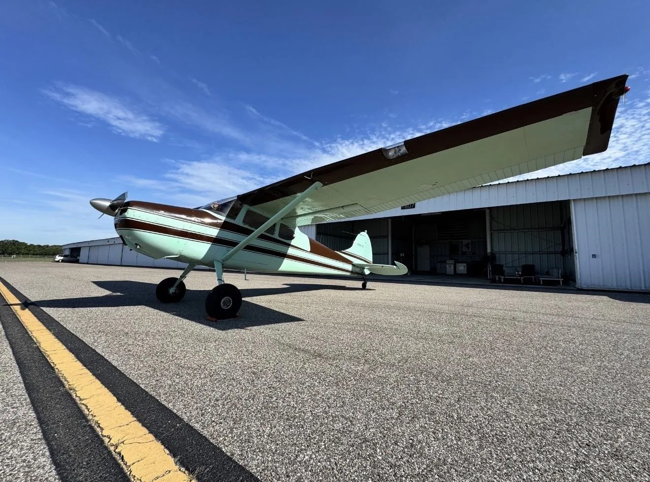
CESSNA 170B for sale now


Free — save the 170B to your watchlist and track it in one place.
More CESSNA 170Bmanuals & documents
See all 41 →- Dynon Certified SkyView HDX Systems DescriptionSystems Description
- Cessna 170 & C305A (USAF O‐1A) T3 Tailwheel Suspension System Installation InstructionsWeight And Balance
- Instructions for Continued AirworthinessSystems Description
- Service Bulletin: SB-001 Rev CService Bulletins
- Component Maintenance Manual for External Design Wheels ...Maintenance Manual
- Instructions for Continued Airworthiness No. ICA17025Weight And Balance
- Technician’s Service GuideTraining Manual
- Aviation Safety Letter ASL 2/2020Emergency Procedures
- Emergency ProceduresEmergency Procedures
- FAA PARTS MANUFACTURING APPROVALS (PMA) & SUPPLEMENTAL TYPE CERTIFICATE APPROVALS (STC)Supplemental Type Certificate
- Type Acceptance Report TAR 8/21B/24 – Cessna 170 SeriesMaintenance Manual
- Cessna Flyer - April 2015Other Documents
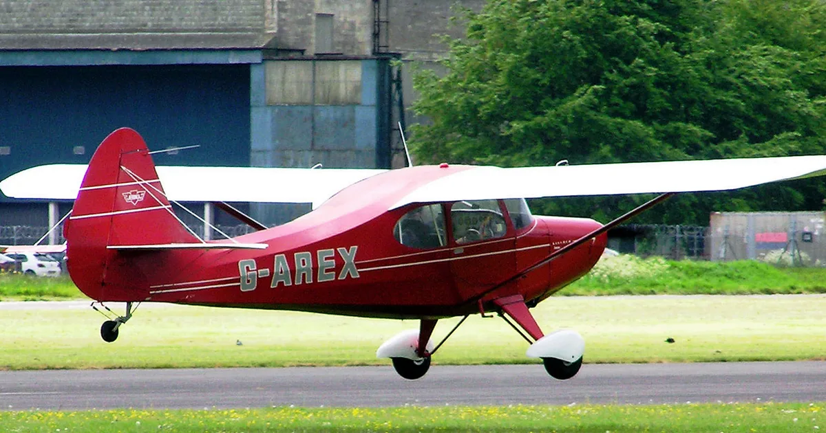
If you fly the CESSNA 170B, you may also be researching these.




In this document
Aircraft Specifications
The Cessna 170 features a high-wing design with a maximum takeoff weight of 2,400 lbs and a useful load of approximately 1,000 lbs. The aircraft is powered by a Continental O-300 engine, providing 145 horsepower. The stall speed in landing configuration is 47 knots, and the cruise speed is around 100 knots.
Operating Limitations
Pilots must adhere to specific operating limitations, including a maximum altitude of 14,000 feet and a maximum speed of 150 knots. The aircraft should not be flown in icing conditions, and the weight and balance must be calculated before each flight.
Emergency Procedures
In case of engine failure, pilots are instructed to maintain control of the aircraft and execute a forced landing. The POH outlines specific steps to follow, including selecting a suitable landing area and managing airspeed.
Performance Data
The Cessna 170 has a takeoff distance of approximately 1,200 feet over a 50-foot obstacle and a landing distance of about 1,000 feet. The rate of climb is approximately 700 feet per minute at sea level.
Weight and Balance
Proper weight and balance calculations are crucial for safe flight operations. The POH provides charts and formulas to assist pilots in determining the center of gravity and ensuring the aircraft is within limits.
Safety notes
- Do not operate in icing conditions.
- Ensure weight and balance calculations are performed before each flight.
Full document text
Cess essna Cessna essna 170 P-125 GRIT 1000-2/5/59 CESSNA AIRCRAFT COMPANY 1951-1952 PRICE $1.00 PRINTED IN U.S.A, OPERATION CESSNA MANUAL 1 7 0 SERIES PREFACE This book has been prepared for you as an owner and oper- ator of a Cessna 170A airplane. It was written specifically for you - to help you get the best out of your airplane - for the longest period of time. Your Cessna is a product of the best in aircraft engineering and production skill. The maintenance of the quality that is built into it will be assured by simple but necessary upkeep on your part. The purpose of this book is to acquaint you with the things you should know - both in operation and care of the airplane. The book is divided into four basic sections. The first concern of the owner of any product is the operation of his equipment. The first section, therefore, sets forth in Pilot's Check List form the basic data that have been developed as the best operational methods for flying your Cessna. It is not a check list in its true form as it is considerably longer, but it does cover briefly all of the points that you would want to or should know concerning the operation of your airplane. Section two of the book sets forth the operation limitations and performance data and should be of useful interest to those desiring the most in performance from their airplane. In the third section are set forth details and explanations that are necessary to avoid complicating the check list to the point where it loses its purpose. The fourth section is devoted to care of the airplane itself and covers your responsibilities to help it perform faithfully and eco- nomically the many hours of fine flying that are built into it. A list of Cessna distributors, who can provide you with service wher- ever you may be, together with a list of approved Cessna accessories has been included in this section for your convenience. WARRANTY The Cessna Aircraft Company warrants each new airplane manufactured to be free from defects in material and workman- ship under normal use and service, provided, however, that this warranty is limited to making good at the Cessna Aircraft Company's factory any part or parts thereof which shall, within ninety (90) days after delivery of such airplane to the purchaser, be returned to the Company with transportation charges prepaid, and which upon Company examination shall disclose to the Company satisfaction to have been thus defective; this warranty being expressly in lieu of all other warranties expressed or implied and all other obligations or liabilities on the part of the Company, and the Company neither assumes nor authorizes any other person to assume for it any other liability in connection with the sale of its airplanes. This warranty shall not apply to any airplane which shall have been repaired or altered outside the Company's factory in any way so as, in its judgment, to affect its stability or reliability, nor which has been subject to misuse, negligence or accident. SECTION - OPERATING CHECK LIST The flight and operational characteristics of the Model 170A Cessna are normal in all respects. There are no "unconventional" characteristics or operations that need to be mastered. All controls respond in the normal way within the entire range of operation of the airplane. A. BEFORE ENTERING THE AIRPLANE (1) Check oil level. Do not operate on less than four quarts. Fill for extended flights. For seaplane note Operating Details. (2) On first flight of the day, drain a small (one-ounce) quan- tity of fuel from fuel strainer drain to insure that no free water is in the fuel line. (3) Check quantity of fuel (two gauges). (4) Make a visual check of the airplane. (5) Remove control locks, if installed. B. BEFORE STARTING THE ENGINE (1) Operate controls and make a rapid visual check for proper operation. (2) Make sure windshield is clean for maximum visibility. (3) Adjust seat for comfort and distance to rudder pedals. (4) Check brakes and set parking brake. (5) Fasten and check safety belt. C. STARTING THE ENGINE (1) Set carburetor heat to "cold." (2) Set mixture control to "full rich." (3) Set fuel tank selector to "both tanks." (Take-off on less than 1/4 tank is not recommended.) (4) If engine is cold (50°F or below), prime the engine as follows: Turn master switch "on." Clear propeller. Make certain magneto switch is "off" and throttle "closed" then give engine three or four strokes with the primer as 3 OPERATING CHECK LIST the engine is turned over. (Ordinarily not required except at winter temperatures.) (5) Turn magneto switches "on." (6) Open throttle 1/8 (to idle position) and start engine by pulling starter control. Note: In extremely cold weather a few strokes of the primer as the engine fires will enable the engine to keep running. (Avoid over-priming.) After priming push primer all the way in and turn to locked position to avoid possibility of engine drawing fuel through the primer. Do not pull out on starter for a second starting attempt until engine has come to a complete stop from the first attempt. Failure to do this may result in damage to the starting gear. D. WARM-UP AND GROUND TEST (1) Do not allow engine to operate at more than 800 r.p.m. for first 60 seconds after starting. (Especially important in cold weather as lubricating oil will be slow in circulating.) After starting if oil gage does not begin to show pressure within 30 seconds in the summertime and about twice that long in very cold weather, stop engine and investigate. Lack of oil pressure may cause serious engine damage. (2) Apply full carburetor heat except under dusty air conditions. (3) After two to three minutes running at 800 r.p.m., open the throttle gradually to 1000 r.p.m. and allow to run for three to five minutes or until engine is sufficiently warm for take-off. Warm-up may be accomplished during taxi- ing. Do not overheat the engine by running engine at high speed while on the ground. It is not necessary to run the
Show full textShow less
engine until oil is "hot"; if engine runs properly at full throttle and oil pressure is normal, you are ready for take-off. E. BEFORE TAKE-OFF 4 (1) Apply toe brakes. (2) Set altimeter. (3) Set trim tab to "take-off" position. (4) Check oil pressure - should show 30 to 40 lbs. sq. in. (Minimum idling oil pressure 5 lbs. sq. in.) CARE 1 RESPONSIBILITIES IV. Empennage and Surfaces. 1. Check both stabilizer, and vertical fin, for possible damage. 2. Check attaching bolts on both fin and stabilizer for security. 3. Check rudder and elevator attaching bolts for security and surfaces for freedom of movement. 4. Check elevator and rudder hinge connections for cracks. 5. Check surface travels to plus or minus 1°. Elevator 28° up and 17° down, Elevator tab 10° up and 27° down, Rudder travel 16° right 16° left, Aileron 20° up 14° down, and Flaps 50° down. 6. Check elevator bellcrank and rudder bellcrank. 7. Clean tail wheel assembly. Check for security, freedom of operation. Grease lube fittings. Pack wheel at 500 hours. Check rubber mounting of springs for wear. V. Cabin Section. 1. Clean cabin section, vacuum it if possible. 2. Inspect rudder bar and brake assembly and the control tee for the security of mounting. Inspect cable connection points. Check pulley installations. 3. Suspend landing gear wheels from floor and remove outer wheel fairings. Shake landing gear and wheels for any sign of looseness and visually inspect fuselage attach- ment. If necessary tighten landing gear bolts and wedges. With airplane in 3-point position on the floor visually inspect landing gear spring leaf underside for cracks. (Remove landing gear wheels and pack with grease every 500 hours unless otherwise designated by owner.) VI. Electrical System. 1. Check electrical system by operating the lights, starter, and all accessories which are incorporated in the electrical system. VII. Recowl the engine. Replace all inspection plates and fairings. VIII. Run engine. 1. Check magnetos for drop. 2. Check generator for proper charge. 53 CARE- 42 52 RESPONSIBILITIES 11. Remove rear center tunnel covers between the front seats. 12. Open curtains at the aft end of the baggage compart- ment for access to the cables, bellcranks and pulleys. It is necessary to crawl back into the fuselage for proper inspection. 13. Open landing gear fairing. II. Engine Check. 1. Remove heater muffs. Inspect mufflers and exhaust stacks for possible cracks. 2. Drain oil and clean oil strainer located on rear side of accessory case and replace oil. 3. Check magneto, touching up points if necessary, and check timing. Right Magneto 26° B.T.C., Left Magneto 28° B.T.C. 4. Check cylinder base nuts for tightness. 5. Check for oil leaks. 6. Remove spark plugs, clean if necessary, check gap spacing and replace. 7. Wash down engine. 8. Check engine mount bolts for security. 9. Check all wires forward of the firewall. 10. Check all engine controls for travel and free movement. 11. Remove and clean gasculator bowl and screen. 12. Check propeller track and inspect for bad nicks or cracks. 13. Check starter travel. 14. Clean carburetor air screen, re-oil and reinstall. 15. Check battery water level. 16. Replace engine cowling. III. Wing Inspection. 1. Check front and rear wing bolts attaching wing to fuse- lage (both wings). 2. Check out strut bolts for security (both wings). 3. Check all wing control surfaces for freedom of movement and bolts for security. 4. Check aileron bellcranks (both sides). 5. Check flap latch and flap pulleys. 6. Drain wing fuel tank sumps. OPERATING CHECK LIST (5) Check engine magnetos at 1600 r.p.m. by opening the throt- tle and switching off separately each magneto momentarily. Drop of r.p.m. from 1600 r.p.m. should not exceed 50 r.p.m. on the right magneto or 75 r.p.m. on the left magneto. Switch to both magnetos before continuing. (6) Check carburetor heat and leave on full heat until take-off. (7) Full throttle r.p.m. check is optional but not recommended. The engine should run smoothly and turn, with carburetor heat off, 2230 to 2330 r.p.m. The engine should idle between 300 and 400 r.p.m. Except for short check do not idle below 600 r.p.m. F. TAKE-OFF (1) Release brakes. (2) Turn carburetor heat "off." (3) For take-off use full throttle, or power required. (4) Heels on the floor. (5) Climb at full throttle, or power required for safety. Best rate of climb airspeed 89 m.p.h. indicated, at sea level. G. CRUISING (1) Recommended maximum cruising r.p.m. 2450. (2) Trim airplane by adjusting elevator tab. (3) Oil pressure - 30-40 lbs. sq. in. (4) Oil temperature - maximum 225°F. (5) Above 5000 ft. lean mixture to 10 or 25 r.p.m. richer than maximum r.p.m. H. BEFORE LANDING (1) Set fuel valve to both tanks. (2) Set mixture control full rich. (3) Apply full carburetor heat before closing throttle. If a long letdown is available, avoid "chopping" the throttle. (4) Suggested glide speed 70-75 m.p.h. (5) Use tab to relieve elevator control wheel pressure when establishing glide. 5 OPERATING CHECK LIST (6) Lower flaps as desired (do not lower flaps when indicated airspeed is above 100 m.p.h.) 1. AFTER LANDING (1) Raise flaps. (2) Normal glide and taxiing should cool engine sufficiently; however, if excessive amount of taxiing is necessary, allow engine to cool before cutting ignition by allowing to idle at 800 r.p.m. two to three minutes. (3) Turn magneto switches "off." (Open throttle to avoid pre-ignition when hot.) Alternate method - Full lean with partially open throttle before turning switches off. (4) Turn radio switch "off." - (5) Turn master switch "off." Be sure otherwise your bat- tery may run down overnight. (6) Set parking brake, if required. CARE RESPONSIBILITIES Distributors carry a full complement of genuine Cessna service parts, complete repair and service facilities, including such spe- cialized jigs and tooling as may be necessary. Cessna dealers maintain stocks of genuine Cessna parts and Service facilities consistent with the demand. An illustrated Parts Catalog for the Model 170 Cessna air- plane is available through distributors and dealers at a nominal charge. The catalog lists optional equipment as well as all standard parts. Your Cessna distributor or dealer will be glad to give you current price quotations on all parts that you might need and will be glad to advise you on the practicability of parts replacement versus repairs that might from time to time be necessary. 100 HOUR INSPECTION: Before beginning the inspection, shop foreman or mechanic runs the engine to check for magneto drop, generator charge and general smoothness of operation of the engine and records these facts as an aid to the mechanic. The inspection consists basically of the following procedure: I. Remove all inspection plates and necessary fairing consisting of the following: 1. Remove front strut inspection plates (both sides). 2. Remove lower half of wing root fairing (both sides). 3. Remove two round inspection plates at aileron bellcrank. 4. Remove two flap pulley inspection covers on top of the wing-root-to-cabin-junction-section forward of the flap. 5. Remove tail group fairing and round plate on left side under the fin. 6. Remove round plate on underneath right side of the stabilizer. 7. Remove lower half of engine cowl. Upper cowl may be clamped together and left on airplane. 8. Remove the two round inspection plates on the under side of the cabin section outside skins. 9. Open the upholstery zipper above the rear seat. 10. Remove the two round plates on the top side of the landing gear bulkhead. 51 CARE - RESPONSIBILITIES INSPECTION SERVICE AND INSPECTION PERIODS: Plan to take your Cessna 170A back to your dealer or distrib- utor after you have flown it for 30 days or about 25 hours, which- ever comes first. This will permit him to check it over, to tighten rocker-box covers, the exhaust manifold installation, and to make any other minor adjustments that might appear necessary. Also, plan a 100-hour inspection by your dealer or distributor at 100 hours or 90 days - whichever comes first. These first two inspec- tion services are performed by your dealer or distributor for you at "No Charge." The Civil Air Regulations require all airplanes to have an "annual inspection" as prescribed by the administrator, by a person designated by the administrator, and in addition, 100 hour periodic inspections made by an "appropriately rated mechanic" if the airplane is flown for hire. The Cessna Aircraft Company recommends the 100 hour periodic inspection for the Model 170A airplanes. The procedure for this 100 hour inspection has been carefully worked out by the factory and is followed by the Cessna dealer and distributor organization. The complete familiarity of the Cessna distributor and dealer organization with Cessna equip- ment and with Cessna procedures provides the highest type of service possible at lower cost. Time studies of the 100 hour inspection at the factory and in the field have developed a standard flat rate charge for this inspection at any Cessna Dealer or Distributor. Points which the inspection reveals require modification or repairs will be brought to the owner's attention by the dealer or distributor and quotations or charges will be made accordingly. The inspection charge does not include the oil required for the oil change. Every effort is made to attract the best mechanics in each com- munity to Cessna service facilities. Many distributors' and dealers' mechanics have attended Cessna Aircraft Company schools and have received specialized instruction in maintenance and care of Cessna airplanes. Cessna service instruction activity in the form of service bulletins and letters is constantly being carried on so that your enjoyment and safety in your Cessna will be complete and up-to-date when you have your inspection and service work per- formed by Cessna distributors' and dealers' mechanics. 50 SECTION II - OPERATION LIMITATIONS+ AND PERFORMANCE DATA OPERATIONS AUTHORIZED: Your Cessna 170A with standard equipment as certificated under CAA Type Certificate No. 799, is approved for day and night operation under VFR. Additional optional equipment is available to increase its utility and to make it authorized for use under IFR day and night. When operated for hire at night, certificated flares are required. An owner of a properly equipped 170A is eligible to obtain approval for its operation on single engine scheduled airline service on VFR. MANEUVERS NORMAL CATEGORY — The Model 170A exceeds the requirements of the Civil Air Regulations, Part 3, set forth by the United States Government for airworthiness. Spins and aerobatic maneuvers are not permitted in normal category airplanes, in compliance with these regulations. In connection with the foregoing, the following gross weights and flight load factors apply: LANDPLANE AND SKIPLANE Gross Weight Flight Load Factor* Flaps Up Flight Load Factor* Flaps Down 2200 lbs. SEAPLANE 2106 lbs. +3.8 -1.52 +3.8 -1.52 +3.5 +3.5 MANEUVERS UTILITY CATEGORY - This airplane is not designed for purely aerobatic flight. How- ever, in the acquisition of various certificates such as commercial pilot, instrument pilot and flight instructor, certain maneuvers are required by the CAA. All of these maneuvers are permitted in the Cessna 170A when operated in the utility category. Your airplane must be operated in accordance with the CAA approved Airplane Flight Manual. If there is any information in this section which contradicts the CAA approved manual, it is to be disregarded. 7 OPERATION AND PERFORMANCE DATA In connection with the Utility category, the following gross weights and flight load factors apply, with recommended entry speeds for maneuvers as shown. LANDPLANE AND SKIPLANE Flight Load Factor* Gross Weight Flight Load Factor* Flaps Up Flaps Down Steep Turns Spins Stalls (Except Whip Stalls) Lazy Eights Chandelles SEAPLANE 1900 lbs. 1975 lbs. +4.4 -1.76 +4.4 -1.76 +3.5 115 m.p.h. +3.5 100 m.p.h. Slow Deceleration Slow Deceleration Slow Deceleration Slow Deceleration 115 m.p.h. 115 m.p.h. 110 m.p.h. 110 m.p.h. Aerobatics that may impose high inverted loads should not be attempted. The important thing to bear in mind in flight maneu- vers is that the Cessna 170A is clean in aerodynamic design and will build up speed quickly with the nose down. Proper speed control is an essential requirement for execution of any maneuver and care should always be exercised to avoid excessive speed which in turn can impose excessive loads. In the execution of all maneu- vers avoid abrupt use of controls. AIRSPEED LIMITATIONS: The following are the certificated true indicated airspeed limits: LANDPLANE AND SKIPLANE Glide or Dive (smooth air) (red line) Level Flight or Climb SEAPLANE 160 m.p.h. 140 m.p.h. 140 m.p.h. 110 m.p.h. (normal range marked with green arc; caution range marked with yellow arc, 140 to 160 m.p.h., sea- plane 110 to 140 m.p.h.) Flap Extension and Operation.. 100 m.p.h. 100 m.p.h. (flap operating range marked by white arc) *The design load factors are 150% of the above and in all cases the structure meets or exceeds design loads. LUBRICATION: CARE - RESPONSIBILITIES Figure 19 outlines the lubrication requirements for the Cessna Model 170A. LIFTING AND JACKING: The airplane may be lifted by an appropriate sling at the engine mount fuselage attachment fitting or by lifting lugs on the engine and a sling around the aft section of the fuselage. The cowl upper halves need not be removed as they can be opened upward for application of the sling at the engine mount fuselage attachment fitting. Jacking point brackets and hoisting rings are available as optional equipment and insure easy, safe handling of the airplane. A block of hardwood sawed at an angle to fit between the fuselage and the landing gear spring may be used as a jacking point to hold the airplane when working on a wheel or tire. Do not use the brake casting as a jacking point. AIRPLANE FILE: There are miscellaneous data, information and licenses that are a part of the airplane file. The following is a check list for that file: A. To be carried in the airplane at all times: (1) Aircraft Registration Certificate (Form ACA 500A) (2) Aircraft Airworthiness Certificate (CAA Form ACA 1362) (3) CAA approved flight manual (4) Airplane Radio installed) (5) Airplane Log Book (6) Engine Log Book Station License (if transmitter B. To be maintained but not necessarily carried in the airplane at all times: (1) Weight and Balance report or latest copy of the Repair and Alteration Form 337 (2) Equipment List (3) A form containing the following information: Model, NC Number, Factory Serial Number, Date of Manufacture, Engine Number and Key Numbers (duplicate keys are available through your Cessna dealer or distributor). 00 8 49 C 25 100 INDICATES LUBRICATION INTERVAL IN HOURS INDICATES TYPE OF LUBRICATION (SEE CODE LETTER) Figure 19 - 500 A - Lubrication Diagram 四 FLAP SETTINGS: For normal take-off For shortest take-off For landing OPERATION AND PERFORMANCE DATA .Up- 0° .Second Notch . Full down 50° ENGINE OPERATING LIMITATIONS: Power and Speed.. Instrument Markings: Oil Temperature Maximum Oil Pressure: Minimum Idling. Normal Operating. Tachometer: Normal Operation.. Cautionary Range Maximum Allowable. 145 b.h.p. at 2700 r.p.m. 225°F. (Red Arc) .5 p.s.i. .30 to 40 p.s.i. .2200-2450 (green arc) .2450-2700 .2700 (red line) Code Letter A - B C-- AN-G-15 - Grease LUBRICATION CODE Carburetor Air Filter - Wash in gasoline, coat both sides with (SAE 10) motor oil and allow to drain before re-installing. Service every 25 hours or oftener when operating in dusty conditions. Engine Oil Tank - Check dip-stick before each flight. Drain and refill every 25 hours. D Brake master cylinders - should be checked and refilled periodically with AN-VV-O-366 (3580-D) Oil-Hydraulic (Petroleum base). NOTE 1. All pulleys, trim tab actuator rod, control surface hinge bearings, bellcrank clevis bolts, flap actuating handle, brake pedal pivots, rudder pedal crossbars, door hinge and mechanism, Bowden controls, throttle, control rod universal (if unsealed) and control column ball, should be lubricated with AN-O-6a General Purpose light machine oil as required or every 1,000 hours. NOTE 2. In general, roller chain (Aileron, Tab wheel, tab actuator) and control cable tend to collect dust, sand, and grit when greased or oiled. More satisfactory operation except under seacoast conditions results when the chains are wiped clean occasionally with a clean dry cloth. 48 WEIGHT AND BALANCE: All aircraft are designed for certain limit loads and balance conditions. These specifications for your 170A are charted on page 10. A weight and balance report and equipment list is furnished with each airplane. All the information on empty weight c.g. and allowable limits for your particular airplane as equipped when it left the factory is shown. Changes in the original equipment affect- ing weight empty c.g. are required by the C.A.A. to be recorded in the repair and alteration form 337. Using the weight empty, c.g. location and moment from the weight and balance report and following the example on Page 10, the exact moment may be readily calculated which when plotted on the upper chart will quickly show whether or not the c.g. is within limits. 9 440 400 360 320 280 240 LOAD WEIGHT-LBS 200 2400 2300 2200 2100 2000 AIRPLANE WEIGHT-LBS 1900 1800 1700 1600 1500 1400 40 50 60 70 ' FRONT SEATS FUEL IN GALLONS 37 160 30 120 20 80 10 80 BAGGAG BAGGAGE IN POUNDS 120 100 40 60 OIL 40 20 о 2 SEAPLANE 80 INDEX UNITS REAR SEATS 06 LOADING GRAPH ADD WEIGHT OF ITEMS TO BE CARRIED TO LICENSED EMPTY WEIGHT OF THE AIRPLANE ADD INDEX UNITS OF THESE ITEMS TO AIRPLANE INDEX UNIT LOCATE THESE TOTALS ON THE CENTER OF GRAVITY ENVELOPE INDEX UNITS = MOMENT -2 о 2 4 8 10 12 14 16 INDEX UNITS 18 20 22 24 26 28 30 EXAMPLE: Empty weight of 1220 lb. moment of 47,900 in. lb. or index of 47.9. EMPTY WEIGHT (LICENSED) OIL PILOT & PASSENGER (1) PASSENGERS (2) FUEL (MAXIMUM) 37 GAL. BAGGAGE (TO MAKE GR. WT.) Total TT TT Locate this point (2200-100.3) on the center of gravity envelope graph, and, since the point falls within the envelope, the above loading meets all balance requirements. WT. INDEX 1220 +47.9 15 -0.3 340 +12.2 340 +23.8 222 +10.7 63 +6.0 .2200 100.3 1000 LANDPLANE CENTER OF GRAVITY ENVELOPE ANY POINT FALLING WITHIN ITS SPECIFIC ENVELOPE MEETS ALL BALANCE REQUIREMENTS 100 110 120 - CIGAR LIGHTER -PHONE JACK _ PHONE JACK ANTENNA MASTER SWITCH IGNITION SWITCH PANEL LIGHTS STALL WARNING FUSES AMMETER -DIMMER 3233 LIGHT NAVIGATION LIGHT/ LANDING WITCH -NAVIGATION LIGHT SWITCH TURN & BANK/ SWITCH -8- -TURN & BANK MICROPHONE JACK TAIL LIGHT 68IGHT PEAKER ANTENNA LOAD COIL- MASTER SOLENOID- BATTERY- STARTER- 47 WARNING STALL ACTUATOR RADIO- NAVIGATION LIGH WHITE RED TRACER WHITE GREEN TEX-29 WHITE & TAN TR. 33 WHITE BLACK TR-32 -LANDING LIGHT -MAGNETO MAGNEREGULATOR -GENERATOR 71 Figure 18 Electrical Wiring Diagram 46 Figure 17-Elevator Tab Control System OPERATION AND PERFORMANCE DATA The utility category is solely for the purpose of instructing and training in certain flight maneuvers. The weight and balance con- siderations limit the airplane to a pilot with or without co-pilot, full gas, no baggage and no rear seat baggage or passenger. The utility category has not been included in the weight and balance charts. OPERATIONAL. DATA: PERFORMANCE INFORMATION — LANDPLANE The following operational data are compiled from actual tests with airplane and engine in good condition and using average piloting technique. Data are based upon a gross weight of 2200 lbs. with McCauley propeller installed, and full throttle for take-off and climb. Performance figures are for zero wind velocity and hard surface level runway. Speeds are true indicated airspeeds. Flaps Down Flaps Up ITEM ALTITUDE OUTSIDE AIR TEMPERATURE 0°F 20°F 40°F 60°F 80°F 100°F Landing Distance* (Ft.) Sea Level 1580 1640 1700 1755 1810 1860 2000 Ft. 1685 1745 1805 1860 1915 1965 4000 Ft. 1790 1850 1910 1970 2020 2075 6000 Ft. 1900 1955 2020 2075 2130 2180 7000 Ft. 1950 2010 2070 2130 2185 2235 To land over 50 ft. obstacle at 71 MPH TIAS approach (Roll 45% distance shown) Take-off Distance* (Ft.) Sea Level To clear 50 ft. obstacle 2000 Ft. at 76 MPH TIAS (ground 4000 Ft. run approx. 40% distance 6000 Ft. 7000 Ft. shown) Normal Rate of Climb Feet per min. Best 89 Sea Level Climb 86 2000 Ft. Speed 84 4000 Ft. TIAS 81 6000 Ft. 79 7000 Ft. PERFORMANCE INFORMATION - SKIPLANE 1460 1580 1700 1820 1930 2050 1780 1910 2050 2190 2340 2500 2140 2290 2450 2610 2790 3000 2550 2740 2930 3140 3360 3620 2820 3040 3260 3500 3750 4040 760 740 715 690 670 645 670 645 625 600 580 555 580 555 535 510 485 465 490 465 440 420 395 370 445 420 395. 370 345 325 Data are based upon a gross weight of 2200 lbs. and full throt- tle for take-off and climb. Performance figures are for zero wind velocity and one inch of snow on grass. Speeds are true indicated airspeeds. Both take-off and landing distances are based on a coefficient of friction of .08 which is representative of dry snow at 10°F. At temperatures lower than 10°F. the take-off distances listed below will be increased. At higher temperatures up to 32°F., the landing distances will be increased. 11 OPERATION AND PERFORMANCE DATA SKI PLANE (Continued) Flaps Down Flaps Up ITEM Landing Distance* (Ft.) To land over 50 ft. obstacle at 71 MPH TIAS approach (Roll 45% distance shown) Take-off Distance* (Ft.) To clear 50 ft. obstacle at 76 MPH TIAS (ground run approx. 55% distance shown) Normal Rate Best of Climb Feet per min. 89 Climb 86 Speed 84 TIAS 81 79 ALTITUDE Sea Level 2000 Ft. 4000 Ft. 6000 Ft. 7000 Ft. Sea Level 2000 Ft. 4000 Ft. 6000 Ft. 7000 Ft. OUTSIDE AIR TEMPERATURE -40°F -20°F 0°F 20°F 40°F 60°F 1650 1720 1790 1855 1925 1995 1765 1835 1905 1975 2045 2110 1885 1955 2030 2095 2165 2235 2000 2075 2145 2215 2290 2360 2065 2135 2210 2280 2350 2420 1380 1505 1615 1770 1910 2055 1680 1715 1980 2140 2320 2500 2070 2250 2440 2640 2850 3080 2550 2780 3020 3280 3560 3870 2840 3100 3380 3680 4000 4360 Sea Level 795 775 755 735 710 690 2000 Ft. 705 685 665 645 625 600 4000 Ft. 615 595 575 555 535 510 6000 Ft. 525 505 485 465 440 420 7000 Ft. 485 460 440 420 395 375 PERFORMANCE INFORMATION - SEAPLANE All performance is given for 2106 pounds gross weight and with zero wind velocity and zero current. Take-off and climb per- formance figures given below were obtained using a propeller with a static r.p.m. of 2350. Performance will be improved using a pro- peller with a higher static r.p.m. Flaps Down Flaps Up ITEM Landing Distance* (Ft.) To land over 50 ft. ALTITUDE OUTSIDE AIR TEMPERATURE 20°F 40°F 60°F °F 80°F 100°F obstacle at 69 MPH TIAS approach. (Water run approx. 35% distance shown) Sea Level 2000 Ft. 4000 Ft. 6000 Ft. 7000 Ft. 1440 1480 1525 1570 1610 1520 1570 1610 1655 1700 1605 1650 1700 1745 1790 1695 1740 1785 1830 1875 1735 1780 1830 1875 1920 Take-off Distance (Ft.) To clear 50 ft. obstacle at 75 MPH TIAS (Water run approx. 60% distance shown) Sea Level 2000 Ft. 4000 Ft. 6000 Ft. 7000 Ft. Normal Rate of Climb Feet per min. Best 73 Climb 72 Speed 72 TIAS 71 70 Sea Level 2000 Ft. 4000 Ft. 6000 Ft. 7000 Ft. 2620 2830 3020 3220 3420 3240 3500 3750 4000 4270 3980 4320 4650 4980 5300 4930 5360 5780 6200 6620 5620 6100 6610 7140 7670 610 595 585 570 555 535 520 510 495 480 450 440 425 410 400 375 360 345 330 315 335 320 305 290 275 *Both take-off and landing distances are reduced approximately 10% for each 6 m.p.h. wind velocity. ELEVATORS: CARE - RESPONSIBILITIES Elevator travel is 28° up and 17° down with a tolerance of plus or minus 1°. This travel is controlled by two stops located in the rear of the fuselage. 1. Set stops (eccentric blocks) so elevator has correct travel when in contact with them. 2. With elevator in full down position, the measurement from firewall to the edge of the chain sprocket hub should be 1/2". 3. Tighten cables to approximately 30 lbs. ELEVATOR TAB: The elevator tab is actuated by a cable which has a chain incorporated in each end. The chain in front is actuated by the fingertip tab control, and the one at the rear operates a screw- jack, which is mounted in the right half of the stabilizer. The travel is 10° up and 27° down, plus or minus 1°. 1. Install cables. Turn tab control wheel to full-forward position, and screwjack to full up position. Then turn screwjack back 12 turn. Set the chain on sprockets at each end, allowing 1/2" to 1" overlap in direction of travel. Tighten cable tension to approximately 30 lbs. 2. To set tab travel, elevator MUST BE in neutral position. 3. Turn tab control to full-forward position, disconnect push-pull tube from tab and adjust it to hold the tab approximately 11°. (This can be done by screwing it in or out, whichever the case may be.) Connect the push-pull tube to the tab and turn the tab control to the full rearward position. The tab should be approximately 28°. 4. Set stops between first and second bulkheads rear of the baggage compartment on the cables for correct travel, which is 10° up and 27° down. ELECTRICAL SYSTEM: Figure 18 outlines the 12-volt electrical system including elec- trical accessories. The numbers indicate wire numbers which can be found on each wire in the actual airplane. 12 45 44 Figure 16- Elevator Control System OPERATION AND PERFORMANCE DATA STALLING SPEED: ANGLE OF BANK DEGREES STALLING SPEED CONDITION 0° 20° 40° 60° MPH TIAS Power Off; Flaps Up 58 60 66 82 Stall Warning Indicator Signal Power Off; Flaps Down 53 55 61 75 Is Evident Power On; Flaps Up Power On; Flaps Down 52 54 59 73 49 51 56 69 The stalling speeds are for forward c.g., normal category, full gross weight conditions. Other loadings result in slower stalling speeds. The horn and light stall warning indicator produces a steady signal 5 to 10 m.p.h. before the actual stall is reached and remains on until the airplane flight attitude is changed. Fast land- ings will not produce a signal. CLIMB: The rate of climb and speed for best climb at various alti- tudes for gross weight of 2200 lbs. and equipped with metal McCauley propeller is given in the table below: Sea Level 2500' 5000' 7500' 10,000' 12,500' 15,000' Density Attitude (Ft.) Best Climb Speed (TIAS) 89 86 82 62 79 75 72 68 Rate of Climb (ft./min.) 690 590 485 380 277 173 68 68 Standard Conditions FLIGHT PROCEDURE: Flight and operational characteristics while already defined as normal, are at an optimum under certain fairly simple techniques. It may be noted for example that perfectly controlled approaches and take-offs may be made at slower speeds than those for average technique tabulated on Pages 11 and 12. The stall-warning indi- cator proves a useful tool when maximum take-off and landing performance is necessary. Landplane and Skiplane Take-off: Set flaps in second notch before take-off, maintain approximately three-point attitude and "fly-off." Slowly raise flaps after climb-out is established. Landplane and Skiplane Cruise: The following table is for full gross weight and standard conditions. Fuel consumption (gallons 13
What's in the CESSNA 170B TCDS
A Type Certificate Data Sheet (TCDS) is the FAA's record of what an aircraft type was approved as. It is the source of truth for weights, seating, fuel and the rules the design was certified against. Expand any line to see what it means.
261 CESSNA 170B parts for sale
See all →
Parts listed for sale by vetted eBay sellers — confirmed on eBay at checkout.