CESSNA 1964 - Wings Over Waxhaw
CESSNA 172C · Pilot's Operating Handbook
Overview
This manual serves as the owner's manual for the Cessna 172 Skyhawk, providing essential information on the aircraft's operation, performance, and maintenance. It is designed for pilots and owners to understand the aircraft's systems, limitations, and procedures to ensure safe and efficient operation. The manual includes detailed specifications, operational data, and checklists, making it a comprehensive resource for both new and experienced pilots. Additionally, it covers weight and balance calculations, which are critical for safe flight operations. The information is applicable to both the standard Cessna 172 and the Reims-Cessna F172, which shares many characteristics with the Cessna 172.
- Gross weight: 2300 lbs
- Top speed: 138 mph at sea level
- Cruise speed: 130 mph at 7000 ft
- Range: 595 miles at 75% power
- Empty weight: approximately 1321 lbs
- Service ceiling: 13,100 ft
- Rate of climb: 645 fpm
Document
Source
Originally published by wingsoverwaxhaw.org. Sprinkle hosts a reference copy with an added summary, specifications and searchable full text.
Document details
- Type
- Pilot's Operating Handbook
- Year
- 1964
- Pages
- 56
- File size
- 32 MB
- Publisher
- wingsoverwaxhaw.org
Specifications & performance
Extracted from this document.
Specifications
- Range (nm)
- 720
- Engine (hp)
- 145
- Height (ft)
- 9
- Length (ft)
- 27
- Propeller
- Fixed Pitch
- Wingspan (ft)
- 36
- Engine model
- O-300-D
- Max speed (kt)
- 121
- Cruise speed (kt)
- 113
- Empty weight (lb)
- 1,260
- Fuel capacity (gal)
- 42
- Rate of climb (fpm)
- 645
- Service ceiling (ft)
- 13,100
- Max takeoff weight (lb)
- 2,300
Performance
- Landing over 50ft
- 520
- Takeoff over 50ft
- 1,260
- Landing distance (ft)
- 865
- Takeoff distance (ft)
- 1,525
Weight & balance
- Useful load (lb)
- 1,040
- Max ramp weight (lb)
- 2,300
- Baggage allowance (lb)
- 120
- Basic empty weight (lb)
- 1,260
- Max landing weight (lb)
- 2,300
- Max takeoff weight (lb)
- 2,300
Common. One of the most common aircraft types we track.
Most owners only have the POH. Here's the essential set for the CESSNA 172C.
CESSNA 172C for sale now


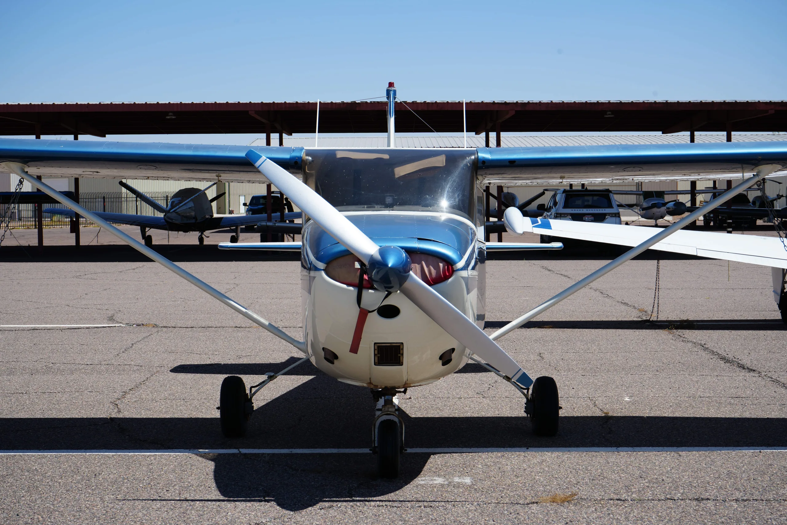
Free — save the 172C to your watchlist and track it in one place.
More CESSNA 172Cmanuals & documents
See all 29 →- Approved Model List For ETX900-TSO Battery InstallationType Certificate
- Service Bulletin SB-12Service Bulletins
- Special Inspection Policy ManualTraining Manual
- CRIMINAL OFFENDER RECORD INFORMATION (C.O.R.I.)Other Documents
- FAA Approved Airplane Flight Manual Supplement for Aerocet Model 2200 Seaplane Float Installation on Cessna Model 172 to 172P and F172D to F172P with Tricycle GearFlight Manual
- Aircraft Weight and Balance ControlPilot's Operating Handbook
- APPROVED MODEL LIST (AML) SA02594SE FOR INSTALLATION OF THE SKYVIEW HDX INSTRUMENTATION AND AUTOPILOT SYSTEMFlight Manual
- SUPPLEMENTAL TYPE CERTIFICATE - 10059692 REV. 1Supplemental Type Certificate
- HAWAII ARMY NATIONAL GUARD (HIARNG) BUILDING 621 RENOVATION AND LATRINE IMPROVEMENTSSpecifications
- Best Glide Speed and DistanceOther Documents
- SUPPLEMENTAL TYPE CERTIFICATE 10051939Supplemental Type Certificate
- Single Engine Service Bulletin SEB07-5 Revision 6, Pilot and Copilot Secondary Seat Stop InstallationService Bulletins
If you fly the CESSNA 172C, you may also be researching these.


In this document
Performance and Specifications
This section outlines the performance metrics of the Cessna 172, including a gross weight of 2300 lbs, a top speed of 138 mph at sea level, and a cruise speed of 130 mph at 7000 ft. The aircraft has a range of 595 miles at 75% power with 39 gallons of fuel. It also details the rate of climb at sea level (645 fpm) and service ceiling (13,100 ft). Landing distances and take-off distances over a 50-foot obstacle are also provided.
Weight and Balance
This section provides guidelines for calculating the weight and balance of the aircraft. It includes a sample loading problem to illustrate how to determine the total weight and moment of the aircraft based on various load conditions. The maximum allowable weight is 2300 lbs, and the empty weight is approximately 1321 lbs. The section emphasizes the importance of ensuring the center of gravity remains within the specified envelope for safe operation.
Operating Limitations
This section specifies the operational limitations for the Cessna 172, including maximum gross weight, load factors, and airspeed limitations. The aircraft is approved for day and night VFR operations and outlines the maneuvers permitted under normal and utility categories. It also includes airspeed limitations, such as a red line speed of 174 mph and a maneuvering speed of 122 mph.
Starting the Engine
Instructions for starting the engine are provided, detailing the necessary steps for both warm and cold starts. The manual emphasizes the importance of checking oil pressure within 30 seconds of starting and provides troubleshooting tips for starting issues.
Checklists
The manual includes various checklists for preflight, engine start, before takeoff, and landing procedures. These checklists are designed to ensure that pilots perform all necessary checks and procedures to operate the aircraft safely.
Safety notes
- Ensure the center of gravity remains within the specified envelope for safe operation.
- Check oil pressure within 30 seconds of starting the engine.
Full document text
CESSNA 1964 MODEL 0122ANO SKYHAWK OWNER'S .,, L MANUAL PERFORMANCE and SPECIFICATIONS -GROSS WEIGHT . • . • • • . . SPEED: Top Speed at Sea Level . • . . Cruise, 75% Power at 7000 ft RANGE: Cruise, 75% Power at 7000 ft 39 Gal. No Reserve Optimwn Range at 10, 000 ft . 39 Gal. No Reserve RATE-OF-CLIMB AT SEA LEVEL. SERVICE CEILING . TAKE-OFF: Ground Run •.• Total Distance Over 50 Foot Obstacle LANDING: Landing Roll . • . • . • . . . . . Total Distance Over 50 Foot Obstacle EMPTY WEIGHT (Approximate) • BAGGAGE ..•.•.•...• WING LOADING: Pounds/Sq Foot POWER LOADING: Pounds/HP FUEL CAPACITY: Total • OIL CAPACITY: Total • . PROPELLER DIAMETER • PROPELLER TYPE . • POWER: Continental Engine No. Horse Power . . . • 172 2300 lbs 138 mph 130 mph 595 miles 4. 6 hours 130 mph 720 miles 7.1 hours 102 mph 645 fpm 13, 100 ft 865 ft 1525 ft 520 ft • 1250 ft 1260 lbs 120 lbs 13.2 15.9 42 gal. 8 qts 76 in. Fixed Pitch * O-300-C 145 SKYHAWK 2300 lbs 139 mph 131 mph 600 miles 4. 6 hours 131 mph 720 miles 7. 1 hours 102 mph 645 fpm 13, 100 ft 865 ft 1525 ft 520 ft 1250 ft 1330 lbs 120 lbs 13.2 15.9 42 gal. 8 qts 76 in. Fixed Pitch O-300-D 145 *The Model Fl 72, which is manufactured by Reims Aviation S. A. , Reims lMarne) France, is identical to the 172 except that it is powered by an 0-300-D engine, manufactured under license by Rolls Royce, Crewe, England. All 172 information in this manual pertains to the Fl72 as well. D209-13 - DUKE - 5000 - 12-66 CONGRATULATIONS ........ . Welcome to the ranks of Cessna owners! Your Cessna has been designed and constructed to give you the most in performance, economy, and corn - fort. It is our desire that you will find flying it, either for business or pleasure, a pleasant and profitable experience. This Owner's Manual has been prepared as a guide to help you get the most pleasure and utility from your 172. It contains information about your Cessna's equipment, operating procedures , and performance; and suggestions for its servicing and care. We urge you to read it from cover to cover, and to refer to it frequently. Our interest in your flying pleasure has not ceased with your purchase of a Cessna. World-wide, the Cessna Dealer Organization backed by the Cessna Service Department stands ready to serve you. The following services are offered by most Cessna Dealers: FACTORY TRAINED MECHANICS to provide you with courteous expert service. FACTORY APPROVED SERVICE EQUIPMENT to provide you with the most efficient and accurate workmanship possible. A STOCK OF GENUINE CESSNA SERVICE PAR'I:'S on hand when you need them. THE LATEST AUTHORITATIVE INFORMATION FOR SERV- ICING CESSNA AIRPLANES, since Cessna Dealers have all of the Service Manuals and Parts Catalogs, kept current by Service Letters and Service News Letters published by Cessna Aircraft Company. We urge all Cessna owners to use the Cessna Dealer Organization to the fullest. A current Cessna Dealer Directory accompanies your new airplane. The Directory is revised frequently, and a current copy can be obtained from your Cessna Dealer. Make your Directory one of your cross-country flight planning aids; a warm welcome awaits you at every Cessna Dealer. ii PRINCIPAL DIMENSIONS * Maximum height of airplane with nose gear depressed and an opt- ional rotating beacon installed. ___ Dz?f!2 ~-<7 and Skyhawk ,__-------------36'-2"--------------1 TABLE OF CONTENTS ====================Page= SECTION I - OPERATING CHECK LIST .............. 1-1 SECTION II - DESCRIPTION AND OPERATING DETAILS ...................... 2-1 SECTION Ill - OPERATING LIMITATIONS ............. 3-1 SECTION IV- CARE OF THE AIRPLANE ............ 4-1 OWNER FOLLOW-UP SYSTEM ........................... 4- s SECTION V - OPERATIONAL DATA ...................... 5-1 SECTION VI - OPTIONAL SYSTEMS ...................... 6-1 ALPHABETICAL INDEX ........................................ lndex-1 iii G) a. b. c. d. e. ® a. @ a. b. @a. ®~: iv Tu 1· n on mast er sw itch and che ck fu el quan- tity indicators, then turn master switch "' OFF. '" Check ignition switches " OFF." Check fuel selector valve handle "BOTH ON." On first flight of day and after each fueling, pull out strainer drain knob for about 4 sec - onds, to c lea r fuel strainer of possible water and sediment. Remove control wheel lock. Che ck baggage door for se c urity (le ft side on ly). Remove gust locks if in stalled. Dis c onn ect tail tie-down . Remove gust l ock, if installed. Check main whee l tire for proper infl ation. Ins pect airspeed static so ur ce hole on side of fuselage for stoppage (left side only). c. @ a. b. c. d . e. !. g. (j) ® a. b. c. ® Figure 1-1 Note Check genera l aircraft condition during walk- ar ound inspection. If night flight is p lanned, check oper- ation of all lights, and make sure a flashlight is available. DiSconnect wing tie-down . Check oil l eve l. Do not operate with l ess - than six quarts. Fill for extended flight. Ch ec k prop ell e r and spinner for nicks and securi ty . Check nose whee l strut for proper inflation. Che ck nose whee l ti re for proper inflation. Disconnect tie - down rope,,. Make visual c heckto insure that fuel strainer drain valve is clos ed after draining operation. Check carbur e tor air filt e r for restrictions by du st or oth er foreign matter. Same as@· R emove pitot tube cover if installed. Inspect pil ot tube opening for stoppage. Che ck fuel tank vent opening for stoppag e. Same as @· •-----"operating check list it One of the first steps in obtaining the utmost performance, service, and flying enjoyment from your Cessna is to familiarize yourself with your airplane's equipment, systems, and controls. This can best be done by reviewing this equipment while sitting in the airplane. Those items whose function and operation are not obvious are covered in Section II. Section I lists, in Pilot's Check List form, the steps necessary to
Show full textShow less
operate your airplane efficiently and safely. It is not a check list in its true form as it is considerably longer, but it does cover briefly all of the points that you would want to or should know concerning the information you need for a typical flight. The flight and operational characteristics of your airplane are normal in all respects. There are no "unconventional" characteristics or opera- tions that need to be mastered. All controls respond in the normal way within the entire range of operation. All airspeeds mentioned in Sections I and II are indicated airspeeds. Corresponding calibrated airspeed may be obtained from the Airspeed Correction Table in Section V. BEFORE ENTERING THE AIRPLANE. (1) Make an exterior inspection in accordance with figure 1-1. BEFORE STARTING THE ENGINE. (1) Seats and Seat Belts -- Adjust and lock. (2) Brakes -- Test and set. (3) Master Switch -- "ON." (4) Fuel Selector -- "BOTH ON." 1-1 STARTING THE ENGINE. (1) Carburetor Heat -- Cold. (2) Mixture -- Rich. (3) Primer -- As required. (4) Ignition Switch -- "BOTH." (5) Throttle -- Open 1/8". (6) Propeller Area -- Clear. (7) Starter -- Engage. BEFORE TAKE-OFF. (1) Throttle Setting -- 1600 RPM. (2) Engine Instruments -- Within green arc and generator light out. (3) Magnetos -- Check (75 RPM maximum differential between mag- netos). (4) Carburetor Heat -- Check. (5) Flight Controls -- Check. (6) Trim Tab -- "TAKE-OFF." (7) Cabin Doors -- Closed and locked. (8) Flight Instruments and Radios -- Set. TAKE-OFF. NORMAL TAKE-OFF. (1) Wing Flaps -- 0° (2) Carburetor Heat -- Cold. (3) Power -- Full throttle (applied smoothly). (4) Elevator Control -- Lift nosewheel at 60 MPH. (5) Climb Speed -- 85 MPH. MAXIMUM PERFORMANCE TAKE-OFF. (1) Wing Flaps -- 0° 1-2 (2) Carburetor Heat -- Cold. (3) Brakes -- Apply. (4) Power -- Full throttle. (5) Brakes -- Release. (6) Elevator Control -- Slightly tail low .. (7) Climb Speed -- 65 MPH (with obstacles ahead). CLIMB. NORMAL CLIMB. (1) Airspeed -- 80 to 90 MPH. (2) Power -- Full throttle. (3) Mixture -- Full rich (unless engine is rough). MAXIMUM PERFORMANCE CLIMB. (1) Airspeed -- 80 MPH at sea level to 77 MPH at 10,000 feet. (2) Power -- Full throttle. (3) Mixture -- Full rich (unless engine is rough. CRUISING. (1) Power -- 2200 to 2700 RPM. (2) Trim Tab -- Adjust. (3) Mixture -- Lean. LET-DOWN. (1) Mixture -- Rich. (2) Power -- As desired. (3) Carburetor Heat -- As required to prevent carburetor icing. BEFORE LANDING. (1) Fuel Selector -- "BOTH ON." (2) Mixture -- Rich. (3) Airspeed -- 70 - 80 MPH (flaps up). (4) Carburetor Heat -- Apply before closing throttle. (5) Flaps -- As desired (below 100 MPH). (6) Airspeed -- 65 to 75 MPH (flaps down). 1-3 NORMAL LANDING. (1) Touchdown -- Main wheels first. (2) Landing Roll -- Lower nosewheel gently. (3) Braking -- Minimum required. AFTER LANDING. (1) Flaps -- Up. (2) Carburetor _Heat -- Cold. SECURE Al RC RAFT. 1-4 (1) Mixture -- Full lean. (2) All Switches - - "OFF." (3) Brakes -- Set. (4) Control Lock -'- Installed. -~-8!'-C-tion 2_-_lt, 9s: operating details The following paragraphs describe the systems and equipment whose function and operation is not obvious when sitting in the airplane. This section also covers in somewhat greater detail some of the items listed in Check List form in Section I. Only those items of the Check List re- quiring further explanation will be found here. FUEL SYSTEM. I Fuel is supplied to the engine from two aluminum tanks, one in each wing. From these tanks, fuel flows by gravity through a selector valve and a strainer to the carburetor. Refer to figure 2-1 for fuel quantity data. For fuel system servicing information refer to Lubrication and Servicing Procedures in Section 4. FUEL QUANTITY DATA (U.S. GALLONS) USABLE FUEL ADDITIONAL UN.USABLE TOTAL TANKS NO. ALL FLIGHT USABLE FUEL FUEL FUEL CONDITIONS (LEVEL FLIGHT) (LEV,EL FLIGHT) VOLUME ' EACH LEFT WING 1 19.5gal. 1. 0 gal. 0. 5 gal. 21. 0 gal. ·RIGHT WING 1 19. 5 gal. 1. 0 gal. 0. 5 gal. 21. 0 gal. Figure 2-1. 2-1 2-2 LEFT FUEL TANK FUEL SYSTEM ····SCHEMATIC···• SELECTOR ,"j VALVE !ii Iii l FUEL STRAINEE THROTTLE __ --lh--1'1 .,,,,...,,,,...,,,.. .~ CARBURETOR ,-- . L---......,----' .................... ~ . TO ENGINE • Figure 2-2 . MIXTURE CONTROL KNOB FUEL STRAINER DRAIN KNOB. Refer to fuel strainer servicing procedures, Section 4. ELECTRICAL SYSTEM. Electrical energy is supplied by a 14-volt, direct-current system powered by an engine-driven generator. A 12-volt storage battery is located on the left-hand forward portion of the firewall. CIRCUIT BREAKERS. All electrical circuits in the airplane, except the clock circuit, are protected by circuit breakers. The clock has a separate fuse mounted adjacent to the battery. The stall warning unit, flap position indicator, turn-and-bank indicator and the optional gyro horizon test lights circuits are protected by a single automatically resetting circuit breaker mounted behind the instrument panel. The cigar lighter is protected by a manually- reset type circuit breaker mounted directly on the back of the lighter be- hind the instrument panel. The remaining circuits are protected by 11 push- to-reset11 breakers on the instrument panel. GENERATOR WARNING LIGHT. The red generator warning light indicates generator output. The light remains off as long as the generator functions properly. If a mal- function interrupts generator output, the light will illuminate. It also will illuminate when the battery or external power is on, before starting the engine, and whenever engine speed is insufficient to produce gen- erator output. The light does not show battery drain. LAN DING LIGHTS. A three-position, push-pull switch controls the optional landing lights. To turn one lamp on for taxiing, pull the switch out to the first stop. To turn both lamps on for landing, pull the switch out to the sec- ond stop. 2-3 CABIN HEATING AND VENTILATION SYSTEM. For cabin ventilation, pull the "CABIN AIR" knob out. To raise the air temperature, pull the "CABIN HT" knob out approximately 1/4" to 1/2" for a small amount of cabin heat. Additional heat is available by pulling the knob out farther; maximum heat is available with the "CABIN HT" knob pulled full out and the "CABIN AIR" knob pushed full in. When no heat is desired in the cabin, the "CABIN HT" knob is pushed full in. STARTING ENGINE. Ordinarily the engine starts easily with bne or two strokes of the primer in warm temperatures to six strokes in cold weather, with the throttle open approximately 1/8 inch. In extremely cold temperatures, it may be necessary to continue priming while cranking. Weak intermittent explosions followed by puffs of black smoke from the exhaust stack indicates overpriming or flooding. Excess fuel can be cleaned from the combustion chambers by the following procedure: Set the mixture control full lean and the throttle full open; then crank the engine through several revolutions with the starter. Repeat the starting procedure without any additional priming. If the engine is underprimed (most likely in cold weather with a cold engine) it will not fire at all, and additional priming will be necessary. As soon as the cylinders begin to fire, open the throttle slightly to keep it running. After starting, if the oil gage does not begin to show pressure within 30 seconds in the summertime and about twice that long in very cold weather, stop engine and investigate. Lack of oil pressure can cause serious engine damage. After starting, avoid the use of carburetor heat unless icing conditions prevail. TAXIING. When taxiing, it is important that speed and use of brakes be held to a minimum and that all controls be utilized (see taxiing diagram, figure 2-3 to maintain directional control and balance. Taxiing over loose gravel or cinders should be done at low engine speed to avoid abrasion and stone damage to the propeller tips. Full 2-4 TAXIING DIAGRAM ~·· CODE WIND DIRECTION t • NOTE Strong quartering tail winds require caution. Avoid sudden bursts of the throttle and sharp braking when the airplane is in this attitude. · use-ffie 5t'::erable nose wheel and rudder to maintain di~-i:),;;jJon. Figure 2-3. 2-5 throttle run-ups over loose gravel are especially harmful to propeller tips. When take-offs must be made over a gravel surface, it is very im- portant that the throttle be advanced slowly. This allows the airplane to start rolling before high RPM is developed, and the gravel will be blown back of ..the propeller rather than pulled into it. When unavoidable small dents appear in the propeller blades, they should be immediately cor- rected as described in Section 4 under propeller care. BEFORE TAKE-OFF. WARM UP. Since the engine is closely cowled for efficient in-flight engine cool- ing, precautions should be taken to avoid overheating during prolonged engine operation on the ground. MAGNETO CHECK. The magneto check should be made at 1600 RPM as follows: Move the ignition switch first to "R" position, and note RPM. Next move the switch back to "BOTH" position to clear the other set of plugs. Then move the switch to the "L" position and note RPM. The difference be- tween the two magnetos operated individually should not be more than 75 RPM. HIGH RPM MAGNETO CHECKS. If there is a doubt concerning the operation of the ignition system, RPM checks at higher engine speeds will usually confirm whether a de- ficiency exists. If a full throjjle run-up is necessary the engine should run smoothly and turn approximately 2230 to 2330 RPM with the car- buretor heat off. An absence of RPM drop Ffiay be an indication of fa:uity grounding of- Y one side of the ignition sy..gfem or should be caul?~ for suspicion that the magneto timing has ]!~eh "bumped-up" and is set in advance of the set- ting specified. 2-6 TAKE-OFF. POWER. CHECK. Since the use of full throttle is not recommended in the static run-up, it is important to check full-throttle engine operation early in the take-off run. Any signs of rough engine operation or sluggish engine acceleration is good cause for discontinuing the take-off. If this occurs, you are justified in making a thorough full-throttle, static run-up before another take-off is attempted. Prior to take-off from fields above 5000 ft. elevation, the mixture should be leaned to give maximum RPM in a full-throttle, static run-up. WING FLAP SETTINGS. Normal and obstacle clearance take-offs are performed with wing flaps up. The use of 10° flaps will shorten the ground run approximately 10%, but this advantage is lost in the climb to a 50-foot obstacle. There- fore the use of 10° flap is reserved for minimum ground runs or for take- off from soft or rough fields with no obstacles ahead. If 10 ° of flaps are used in ground runs, it is preferable to leave them extended rather than retract them in the climb to the obstacle. The ex- ception to this rule would be in a high altitude take-off in hot weather where climb would be marginal with flaps 10° (1st notch). Flap deflections of 30° to 40 ° are not recommended at any time for take-off. PERFORMANCE CHARTS. Consult the take-off chart in Section 5, for take-off distances under various gross weight, altitude, and headwind conditions. CROSSWIND TAKE-OFFS. Take-offs into strong crosswinds normally are performed with the minimum flap setting necessary for the field length, to minimize the drift angle immediately after take-off. The airplane is accelerated to 2-7 a speed slightly higher than normal, then pulled off abruptly to prevent possible settling back to the runway whil{;) drifting. When clear of the ground, make a coordinated turn into the wind to correct for drift. CLIMB. For detailed data, refer to the Climb Performance Charts in Section 5. CLIMB SPEEDS. Normal climbs are performed at 80 to 90 MPH with flaps up and full throttle for best engine cooling. The mixture should be full rich unless the engine is rough due to too rich a mixture. The best rate of climb speeds range from 80 MPH at sea level to 77 MPH at 10, 000 feet. If an obstacle dictates the use of a steep climb angle, the best angle-of- climb speed should be used with flaps up and full throttle. These speeds vary from 65 MPH at sea level to 71 MPH at 10, 000 feet. NOTE Steep climbs at these low speeds should be of short duration to improve engine cooling. CRUISE. Normal cruising is done between 65% and 75% power. The power settings required to obtain these powers at various altitudes and outside air temperatures can be determined by using your Cessna Power Computer. Cruising can be done most efficiently at high altitudes because of lower air density and therefore lower airplane drag. This is illustrated in the following table which shows performance at 75% power at various altitudes. 2-,8 TRUE ALTITUDE RPM AIRSPEED RANGE Sea Level *2450 123 565 5000 ft. *2560 128 585 7000 ft . *Full Throttle 130 595 •75% Power All figures are based on lean mixture, 39 gallons of fuel (no re- serve), zero wind, standard atmospheric conditions, and 2300 pounds gross weight. STALLS. The stall characteristics are conventional and aural warning is pro- vided by a stall warning horn which sounds between 5 and 10 MPH above the stall in all configurations. Power-off stall speeds at maximum gross weight and aft c. g. con- dition are presented on page 5-2 as calibrated airspeeds. LANDING. Normal landings are made power-off with any flap setting. Slips are prohi b ited in full flap approaches b ecause of a downward pitch en- countered under certain combinations of airspeed and sideslip angle. SHORT FIELD LANDINGS. For a short field landing, make a power-off approach at approxi- mately 67 MPH with flaps 40° (fourth notch) and land on the main wheels first. Immediately after touchdown, lower the nose gear to the ground and apply heavy b raking as required. Raising the flaps after landing will provide more efficient braking. CROSSWIND LANDINGS. When landing in a strong crosswind, use the minimum flap setting reciufred for the field length. Use a wing-low, crab , or a combination method of drift correction and la nd in a nea rly level attitude . Hold a 2-9 straight course with the steerable nosewheel and occasional braking if necessary. COLD WEATHER OPERATION. Prior to starting on cold morning , it is advisable to pull the pro- peller through several times by hand to "break loose" or " limber" the oil , thus conserving battery energy. In extremely cold (0 °F and lower) weather,the use of an external preheater for both the engine and battery is recommended whenever possible to reduce wear and abuse to the engine and the electrical system. When using an external power source, the position of the master switch is important. Refer to Section 6, GROUND SERVICE PLUG RECEPTACLE, for operating details. Cold weather starting procedures are as follows: 2-10 With Pre heat: (1) Clear propeller. (2) Pull master switch "ON." (3) With magneto switch " OFF" and throttle closed , prime the engine four to ten strokes as the engine is being turned over. NOTE Use heavy strokes of primer for best atomization of fuel. After priming, push primer all the way in and turn to locked position to avoid possibility of engine drawing fuel through the primer . (4) Turn magneto switch to " BOTH." (5) Open throttle 1/ 4" and engage starter. Without Preheat: (1) Prime the engine 8 to 10 strokes while the propeller is being turned by hand. (2) Clear propeller. (3) Pull master switch "ON." (4) Turn magneto switch to "BOTH." (5) Open throttle 1/ 4" . (6) Pull carburetor air heat knob full on. (7) Engage starter and continue to prime eng ine unm His 1."U'i'J,,,-_,, ning smoothly . MODIFIED FUEL MANAGEMENT PROCEDURES With a combination of highly volatile fu.el, high fuel temperature, high operating altitude, and low fuel flow rate in. the tank outlet lines, there is a remote possibility of accumulating fuel vapor and encountering power ir- regularities on some airplanes, To minimize this possibility, the follow- ing operating procedures are recommended.: (1) Take-off and climb to cruise altitude on "both" tanks, (This is consistent with current recommendations.) (2) When reaching cruise altitude above 5000 feet MSL, promptly switch the fuel selector valve from "both" tanks to either the "right" or "left" tank. (3) During cruise, use "left" and "right" tank as required. (4) Select "both" tanks for landing as currently recommended. POWER RECOVERY TECHNIQUES In the remote event that vapor is present in sufficient amounts to cause a power irregularity, the following power recovery techniques should be followed: OPERATION ON A SINGLE TANK Should power irregularities occur when operating on a single tank, power can be restored immediately by switching to the opposite tank. In addition, the vapor accumulation in the tank on which the power irregu- larity occurred will rapidly dissipate itself such that that tank will also be available for normal operation after it has been unused for approximately one (1) minute. OPERATION ON BOTH TANKS Should power irregularities occur with the fuel selector on both tanks, the following steps are to be taken to restore power: (1) SWitch to a single tank for a period of 60 seconds. (2) Then switch to the opposite tank and power will be restored. =====Note,===== 2-12 .._ection ~ -, -~-" .... - 9s: operating limitations OPERATIONS AUTHORIZED. Your Ces-sna with standard equipment as certificated under FAA Type Certidicate No. 3A12 is approved for day and night operation under VFR . Additional optional equipment is available to increase its utility and to make it authorized for use under IFR day and night. An owner of a properly equipped Cessna is eligible to obtain approval for its operation on single-engine scheduled airline service on VFR. MANEUVERS - NORMAL CATEGORY. The airplane exceeds the requirements of the Civil Air Regulations, Part 3, set forth by the United States Government for airworthiness. Spins and aerobatic maneuvers are not permitted in normal category air- planes in compliance with these regulations. In connection with the fore- going, the following gross weights and flight load factors apply: Gross Weight. . . . . . . . . . Flight Load Factor * Flaps Up . . Flight Load Factor * Flaps Down . *The design load factors are 150% of the above and in all cases the structure meets or exceeds design loads. . 2300 lbs. +3. 8 -1. 52 +3.5 Your airplane must be operated in accordance with all FAA approved markings, placards and check lists in the airplane. If there is any infor- mation in this section which contradicts the FAA approved markings, pla- cards and check lists, it is to be disregarded. 3-1 MANEUVERS - UTILITY CATEGORY. This airplane is not designed for purely aerobatic flight. However, in the acquisition of various certificates such as commercial pilot, in- strument pilot and flight instructor, certain maneuvers are required by the FAA. All of these maneuvers are permitted in this airplane when operated in the utility category. In connection with the utility category, the following gross weight and flight load factors apply, with recom- mended entry speeds for maneuvers as shown. Maximum Design Weight . . . ..... Flight Maneuvering Load Factor, Flaps Up Flight Maneuvering Load Factor, Flaps Down . 2000 lbs. +4. 4 -1. 76 +3. 5 No acrobatic maneuvers are approved except those listed below: Maneuver Entry Speed Chandelles . 122 mph (106 knots) Lazy Eights. 122 mph (106 knots) Steep Turns. 122 mph (106 knots) Spins Slow Deceleration Stalls (Except Whip Stalls) Slow Deceleration The baggage compartment and rear seat must not be occupied. Aerobatics that may impose high inverted loads should not be attempted. The important thing to bear in mind in flight maneuvers is that your Cessna is clean in aerodynamic design and will build up speed quickly with the nose down. Proper speed control is an essential re- quirement for execution of any maneuver and care should always be exercised to avoid excessive speed which in turn can impose excessive loads. In the execution of all maneuvers avoid abrupt use of controls. AIRSPEED LIMITATIONS. RED LINE . . 174 mph YELLOW ARC 140-174 mph GREEN ARC . 59-140 mph WHITE ARC . 52-100 mph MANEUVERING SPEED* 122 mph *The maximum speed at which you can use abrupt control travel without exceeding the design load factor. 3-2 NOTE RED LINE .. YELLOW ARC GREEN ARC. WHITE ARC . Maximum Speed (Glide or dive , smooth air). Caution Range (L evel flight or climb). Normal Range (L evel flight or climb). Flap Operating Range ENGINE OPERATION LIMITATIONS. Power and Speed: ENGINE INSTRUMENT MARKINGS. OIL TEMPERATURE GAGE. Normal Operating Range Maximum Allowable OIL PRESSURE GAGE. Minimum Idling . . . . . Normal Operating Range . Maximum.· ...... . FUEL QUANTITY INDICATORS. 145 bhp at 2700 rpm Cireen Arc Red Line 10 psi (red line) 30-60 psi (green arc) . . 100 psi (red line) EMPTY . . . ...• . . . . . . . . . E (red line) 1. 50 gallons unusable each tank TACHOMETER. Normal Operating Ran ge : At sea level (inner green arc). At 5000 feet (middle green arc) . At 10,000 feet (outer green arc). Maximum Allowable (Red line) . . . 2200-2500 2200-2600 2200-2700 2700 3-3 WEIGHT AND BALANCE. The following information will enable you to operate your Cessna within the prescribed weight and center of gravity limitations. To figure the weight and balance for your particular airplane, use the Sample Problem, Loading Graph, and Center of Gravity Moment Envelope as follows: Take the licensed Empty Weight and Moment/1000 from the Weight and Balance Data sheet, plus any changes noted on forms FAA-337, carried in your airplane, and write them down in the proper columns. Using the Loading Graph determine the moment/1000 of each item to be carried. Total the weights and moments/1000 and use the Center of Gravity Moment Envelope to determine whether the point falls within the envelope and if the loading is acceptable. 172 Sample Airplane Your Airplane SAMPLE LOADING PROBLEM Weight Moment Weight Moment (lbs) (I b - ins. --- /1000) 1. Licensed Empty Weight (Sample Airplane) ••• 1321 50,4 2. Oil 8 Qts.• ·········································· 15 -0.3 15 -0.3 3, Pilot & Front Passenger••••••••••••••••••••••••••••• 340 12.2 4, Fuel- (39 Gal at 6#/Gol) .......................... 234 11,2 5. Rear Passengers ...................................... 340 23.8 6. Baggage (or Passenger on Auxiliary Seat) •••••• 50 4.7 7, Total Aircraft Weight (Loaded) ............ ,., ••• 2300 102,0 111111111 8. Locate this point {2300atl02.0) on the center of gravity envelope, and since this point falls within the envelope the loading is acceptable. *Note: Normally lull oil may be assumed for all flights. 3-4 Ic..:, I 01 • 400 LOADING GRAPH 360 320 00 § 280 g - 240 E-a :z:: 9 200 rzl ~ 1111111111111111111111130 GAL. 5! 160 s 120 20 GAL. 80 10 GAL. 40 0 -2 I o I 2 I 4 I 6 I -1 1 3 5 7 39 GAL. (MAX.) CODE PILOT AND FRONT PASSENGER FUEL ( 39 GAL. MAX. @ 6# /GAL. ) REAR PASSENGERS ••••••m····· BAGGAGE or Passenger on Auxiliary Seat ( 120# MAX. ) 8 I 10 I 12 I 14 I 16 I 18 I 20 I 22 I 24 I 26 I 28 I 30 9 11 13 15 17 19 21 23 25 27 29 MOMENT/1000 ( POUND-INCHES) i:.., I a, 2300 m CENTER OF GRAVITY MOMENT ENVELOPE ~ 2200 ll llllllllllllllllllll~llll lllll lllm1 1111 1 m111111 1111 11Rlll c~~~~~;y . ~ 2100 - ~ § 2000 ra::i ~ i ::::1 111111111 11 1111111111111111111\~ ~ A 1700 ra::i A ~ 1600 ..:I 1500 45 50 . 55 60 65 70 75 80 85 90 95 100 105 110 -,_ LOADED AIRCRAFT MOMENT /1000 (POUND-INCHES) 4 _-_-:_, care of the airplane it If your airplane is to retain that new plane performance and depend- ability, certain inspection and maintenance requirements must be fol- lowed. It is always wise to follow a planned schedule of lubricaUon and maintenance based on the climatic and flying conditions encountered in your locality. Keep in touch with your Cessna Dealer and take advantage of his know- ledge and experience. He knows your airplane and how to maintain it. He will remind you when lubrications and oil changes are necessary and about other seasonal and periodic services. GROUND HANDLING. The airplane is most easily and safely maneuvered by hand with the tow-bar attached to the nosewheel. NOTE When using the tow-bar, never exceed the turning angle of 30 °, either side of center, or damage to the gear will result. MOORING YOUR AIRPLANE. Proper tie-down procedure is your best precaution against damage to your parked airplane by gusty or strong winds. To tie-down your air- plane securely, proceed as follows: (1) Set the parking brake and install the control wheel lock. (2) Install a surface control lock between each aileron and flap. (3) Tie sufficiently strong ropes or chains (700 pounds tensile strength) to wing, tail, and nose tie-down fittings and secure each rope to ramp tie-down. 4-1 (4) Install a surface control lock over the fin and rudder. (5) Install a pitot tube cover. WINDSHIELD -WINDOWS. The plastic windshield and windows should be kept clean and waxed at all times. To prevent scratches and crazing, wash them carefully with plenty of soap and water, using the palm of the hand to feel and dislodge dirt and mud. A soft. cloth, chamois or sponge may be used, but only to carry water to the surface. Rinse thoroughly, then dry with a clean, moist chamois. Rubbing the surface of the plastic with a dry cloth builds up an electrostatic charge so that it attracts dust particles in the air. Wiping with a moist chamois will remove both the dust and this charge. Remove oil and grease with a cloth moistened with kerosene. Never use gasoline, benzine, alcohol, acetone, carbon tetrachloride, fire ex- tinguisher or anti-ice fluid, lacquer thinner or glass cleaner. These materials will soften the plastic and may cause it to craze. After removing dirt and grease, if the surface is not badly scratched, it should be waxed with a good grade of commercial wax. The. wax will fill in minor scratches and help prevent further scratching. Apply a thin, even coat of wax and bring it to a high polish by rubbing lightly with a clean, dry, soft flannel cloth. Do not use a power buffer; the heat gen- erated by the buffing pad may soften the plastic. Do not use a canvas cover on the windshield unless freezing rain or sleet is anticipated. Canvas covers may scratch the plastic surface. PAINTED SURFACES. The painted exterior surfaces of your new Cessna require an initial curing period which may be as long as 90 days after the finish is applied. During this curing period some precautions should be taken to avoid dam - aging the finish or interfering with the curing process. The finish should be cleaned only by washing with clean water and mild soap, followed by a rinse with water and drying with cloths or a chamois. Do not use polish or wax, which would exclude air from the surface, during this 90-day curing period. Do not rub or buff the finish and avoid flying through rain, hail or sleet. Once the finish has cured completely, it may be waxed with a good 4-2 automotive wax. A heavier coating of wax on the leading edges of the wings and tail and on the engine nose cap and propeller spinner will help reduce the abrasion encountered in these areas. ALUMINUM SURFACES. The clad aluminum surfaces of your Cessna require only a minimum · of care to keep theni bright and clean. The airplane may be washed with clear water to remove dirt; oil and grease may be removed with gas.oline, naphtha , carbon tetrachloride or other non-alkaline solvents. ·nulled aluminum surfaces may be cleaned effectively with an aircraft aluminum polish. · After cleaning, and periodically thereafter, waxing with a good auto- motive wax will preserve the bright appearance and retard corrosion. Regular waxing is especially recommended for airplanes operated in salt water areas as a protection against corrosion. PROPELLER CARE. Preflight inspection of propeller blades for nicks , and wiping them occasionally with an oily cloth to clean off grass and bug stains will as- sure long , trouble-free service. It is vital that small nicks on the pro- pellers , particularly near the tips and on the leading edges , are dressed out as soon as possible since these nicks produce stress concentrations, and if ignored, may result in cracks. Never use an alkaline cleaner on . the blades; remove grease and dirt with carbon tetrachloride or Stoddard solvent. INTERIOR CARE. To remove dust and loose dirt from the upholstery , headliner , and carpet, clean the interior regularly with a vacuum cleaner . . Blot up any spilled liquid promptly, with cleansing tissue or rags. Don't pat the spot; press the blotting material firmly and hold it for . sev- eral seconds. Continue blotting until no more liquid is taken up. Scrape off sticky materials with a dull knife , then spot-clean the area. Oily spots may be cleaned with household spot removers, used spar- ingly. Before using any solvent, read the instructions on the container and test it on an obscure place on the fabric to be cleaned. Never satu- rate the fabric with a volatile solvent; it may damage the padding and backing materials. · Soiled upholstery and carpet may be cleaned with foam -type detergent, used according to the manufacturer's instructions. To minimize wetting the fabric, keep the foam as dry as possible and remove it with a vacuum cleaner. The plastic tri.m, instrument panel and control knobs need only be wiped off with a damp cloth. Oil and grease on the control wheel and control knobs can be removed with a cloth moistened with kerosene. Volatile solvents, such as mentioned in paragraphs on care of the wind- sheid, must never be used since they soften and craze the plastic. INSPECTION SERVICE AND INSPECTION PERIODS. With your airplane you will receive an Owner's Service Policy. Cou- pons attached to the policy entitle you to an initial inspection and the first 100-hour inspection at no charge. If you take delivery from your Dealer, he will perform the initial inspection before delivery of the airplane to you. If you pick up the airplane at the factory, plan to take it to your Dealer reasonably soon after you take delivery on it. This will permit him to check it over and to make any minor adjustments that may appear necessary. Also, plan an inspection by your Dealer at 100 hours or 90 days, whichever comes first. This inspection also is performed by your Dealer for you at no charge. While these important inspections will be performed for you by any Cessna Dealer, in most cases you will prefer to have the Dealer from whom you purchased the airplane accomplish this work. Civil Air Regulations require that all airplanes have a periodic (annual) inspection as prescribed by the administrator, and performed by a person designated by the administrator. In addition, 100-hour periodic inspections made by an "appropriately-rated mechanic" are required if the airplane is fl.own for hire. The Cessna Aircraft Company recommends the 100-hour periodic inspection for your airplane. The procedure for this 100-hour inspection has been carefully worked out by the factory and is followed by the Cessna Dealer Organization. The com - plete familiarity of the Cessna Dealer Organization with Cessna equip- ment and with factory-approved procedures provides the highest type of service possible at lower cost. 4-4 = =.~.~.- 0 W N E R F O LL O W - U P SY STE M _ ~·· Your Cessna Dealer has an owner follow-up system to notify you when he receives information that applies to your Cessna . In addition, if you wish, you may choose to receive similar notification directly from the Cessna Service Department. A subscription card is supplied in your airplane file for your use , should you choose to request this ser- vice. Your Cessna Dealer will be glad to supply you with details con- cerning these follow-up programs, and stands ready through his Service Department to supply you with fast, efficient, low cost service. AIRPLANE FILE. There are miscellaneous data, information and licenses that are a part of the airplane file. The following is a check list for that file. In addition, a periodic check should be made of the latest Civil Air Regu- lations to insure that all data requirements are met. A. To be displayed in the airplane at all times: (1) Aircraft Airworthiness Certificate (Form FAA-1362). (2) Aircraft Registration Certificate (Form FAA-500A). (3) Airplane Radio Station License (Form FCC-404, if transmitter installed), B. To be carried in the airplane at all times: (1) Weight and Balance, and associated papers (latest copy of the Repair and Alteration Form, Form FAA-337, if applicable). (2) Airplane Equipment List. C. To be made available upon request: (1) Airplane Log Book. (2) Engine Log Book. NOTE Cessna recommends that these items plus the Owner's Manual and the "Cessna Flight Guide" (Flight Computer) be carried in the airplane at all times. Most of the items listed are required by the United States Civil Air 4-5 Regulations. Since the regulations of other nations may require other documents and data, owners of exported airplanes should check with their own aviation officials to determine their individual requirements. LUBRICATION AND SERVICING PROCEDURES Specific servicing information is provided here for items requiring daily attention. A Service Frequency Check List is included to inform the pilot wh!;!n t.o have other items checked a11(l, servic~d. DAILY FUEL TANK FILLERS: Service after each flight with 80 / 87 minimum grade fuel. The capacity of each wing tank is 21 gallons. FUEL STRAINER: On the first flight of the day and after each refueling, pull out fuel strainer drain knob for about four seconds, to clear fuel strainer of possible water and sediment. Release drain knob, then check that strainer drain is closed after draining. OIL FILLER: When pl'eflight check shows low oil level, service with aviation grade engine oil ; SAE 20 below 40°F. and SAE 40 above 40 ° F. Your Cessna was delivered from the factory with straight mineral oil (non- detergent) and should be operated with straight mineral oil for the first 25 hours . The use of mineral oil during the 25-hour break-in period will help seat the piston rings and will result in less oil con- sumption. After the first 25 hours, either mineral oil or detergent oil may be used. If a detergent oil is used, it must conform to Continental Motors Corporation Specification MHS-24. Your Cessna Dealer can supply an approved brand. OIL DIPSTICK : 4-6 Check oil level before each flight . Do not operate on less than 6 quarts and fill if an extended flight is planned. The oil capacity of the engine is 8 quarts. SERVICING INTERVALS CHECK LIST EACH 25 HOURS BATTERY -- Check and Service. ENGINE OIL -- Change. ENGINE OIL SCREEN -- Clean. INDUCTION AIR FILTER -- Clean or Replace. Under extremely dusty conditions, daily maintenance of the filter is recommended. NOSE GEAR TORQUE LINKS -- Lubricate. EACH 100 HOURS BRAKE MASTER CYLINDERS -- Check and fill. GYRO INSTRUMENT AIR FILTERS (OPT) -- Replace. Replace soon- er if erratic or sluggish responses are noted with normal suction gage readings. SHIMMY DAMPENER -- Check and fill. SUCTION RELIEF VALVE INLET SCREEN -- Check inlet screen for dirt or obstructions. FUEL TANK SUMP DRAINS -- Drain water and sediment. FUEL l.JNE DRAIN PLUG -- Drain water and sediment. VACUUM SYSTEM OIL SEPARATOR -- Clean. EACH 500 HOURS WHEEL BEARINGS -- Lubricate. Lubricate at first 100 hours and at 500 hours thereafter. 4-7 ====Note,===== 4-8 5 _-:_-_, oper~tional data The Operational Data sllown on tile following pages are compiled from actuartests with airplane and engine in good condition and using average piloting·lechnique and best power mixture. You will find tllis data a valu- able aid when planning your fligllts. However, inasmucll as tile number of variables included precludes great accuracy, an ample fuel reserve should be provided. Tile range performance shown makes no allowance for wind, navigational error, pilot technique, warm-up, take-off, climb, etc. All of tllese factors must be considered wllen estimating reserve fuel. A power setting selected from the range charts usually will be more efficient than a random setting, since it will permit you to estimate your fuel consumption more accurately. You will find that using the charts and your Power Computer will pay dividends in overall efficiency. Range and endurance figures shown in the cllarts are based on flight test using McCauley 1Cl72 / EM 7653 propeller. Otller conditions of the tests are shown in the cllart lleadings. Allowances for fuel reserve, lleadwinds, take-offs, and climb, and variations in mixture leaning tecllnique sllould be made and are in addition to those shown on the charts. Other indeterminate variables sucll as carburetor metering-cllaracteristics, engine and propeller conditions, and turbulence of atmosphere may account for variations of 10% or more in maximum range. 5-1 AIRSPEED CORRECTION TABLE FLAPS IAS 40 50 60 70 80 90 100 110 120 130 140 FLAPS UP CAS 55 60 66 72 80 89 98 108 117 127 136 FLAPS DOWN CAS 52 58 65 73 82 91 101 • • • • Figure 5-1. POWER OFF 5 TA L. LI NG · 5 PEE O 5 MPH - CAS ANGLE Of BANK I CONDITION oo I 20° I 40° I 60 ° FLAPS UP 57 59 65 81 2300 LBS . GROSS FLAPS 10 ° 52 54 59 74 WEIGHT FLAPS 40° 49 51 56 69 Fi g ur e 5-2 . 5-2 c:,, I c.:, TAKE-OFF DATA TAKE-OFF DISTANCE FROM HARD SURFACE RUNWAY, FLAPS UP GROSS IA$ HEAD @ S.L. & 59° F @ 2500 ft. & 50° F @ 5000 It. & 41 ° F @ 7500 It . & 32° F WEIGHT AT 50 FT , WIND GROUND TO CLEAR GROUND TO CLEAR GROUND TO CLEAR GROUND TO CLEAR LBS. MPH KNOTS RUN 50' OBS. RUN 50 ' OBS. RUN 50 ' OBS. RUN 50' OBS. 0 435 780 520 920 625 1095 765 1370 1700 60 10 290 570 355 680 430 820 535 i040 20 175 385 21 5 470 270 5 75 345 745 0 630 1095 75 5 1325 905 1625 ll20 2155 2000 65 10 435 820 530 1005 645 1250 810 1685 20 275 580 340 720 425 910 595 1255 0 865 1525 1040 1910 1255 2480 1565 3855 2300 70 10 615 1170 750 1485 920 1955 1160 3110 20 405 850 505 1100 630 1480 8 10 2425 NOTE: Increase distance 10% for each 25°F above standard temperature for particular altitude. Figure 5-3. MAXIMUM RATE-OF-CLIMB DATA @ S. L. & 59° F @ 5000 FT & 41 ° F @ 10,000 FT & 23 ° F @ 15,000 FT & 5° F GROSS IA$ RATE OF GALS IAS RATE OF FROM IAS RATE OF FROM IAS RATE OF FROM WEIGHT MPH CLIMB OF FUEL MPH CLIMB S. L. MPH CLIMB S.L. MPH CLIMB S.L. FUEL FUEL FUEL LBS. FT / MIN, USED FT / MIN . USED FT/MIN. USED FT / MIN. USED 1700 75 1085 1.0 73 825 1.9 71 570 2 .9 70 315 4.4 2000 77 840 1.0 76 610 2.2 74 380 3 .6 73 155 6 . 3 2300 80 645 1.0 78 435 2.6 77 230 4,8 76 22 11.5 NOTE: Flaps up , full throttle and mixture leaned for smooth operation above 5000 ft. fuel used includes warm-up and take-off allowance. Figure 5-4. 172 SKYHAWK Gross Weight - 2300 lbs . • Standard Conditions • CRUISE & RANGE PERFORMANCE Zero Wind• lean Mi xture • 39 Gal. of Fuel (No Reserve) NOTE: Maximum cruise is normally limited to 75 % power . For standard 172 performance, subtract 1 MPH from the higher cruise speeds shown. % TAS GAL . / ENOR. RANGE ALT. RPM BHP MPH HOUR HOURS MILES 2500 2700 93 138 10. 5 3 .7 510 2600 84 131 9. 5 4. 1 540 2500 75 125 8. 5 4. 6 575 2400 67 119 7.6 5. 1 610 2300 59 113 6.8 5.7 645 2200 52 106 6. 2 6 .3 675 2100 46 100 5. 7 6 .9 690 5000 2700 87 13 6 9.B 4. 0 540 2600 7B 130 8. 8 4 .4 575 2550 74 127 8.4 4.7 590. 2500 70 124 7.9 4.9 610 2400 62 118 7. 1 5. 5 645 2300 55 111 6. 4 6 .1 675 2200 49 105 5.9 6. 6 695 2100 44 98 5. 5 7. 1 700 7500 2650 77 132 B.7 4 .5 595 2600 73 129 8. 2 4 .7 610 2500 65 123 7. 4 5. 3 645 2400 58 11 6 6 .7 5. 8 67 5 2300 52 110 6.1 6.4 700 2200 47 103 5 .7 6. 9 71 0 2100 42 97 5.3 7.3 710 10, 000 2700 71 131 8. 1 4.8 630 2600 68 128 7. 7 5. 1 650 2500 61 121 7. 0 5 .6 680 2400 55 11 5 6. 4 6. 1 705 2300 49 108 5. 9 6. 6 715 2200 45 102 5. 5 7. 1 720 2100 41 96 5.2 7.4 71 5 12,500 2600 63 126 7.2 5.4 685 2500 57 120 6. 6 5.9 710 2400 52 113 6. 1 6. 4 725 2300 47 107 5. 7 6.8 730 I 2200 43 101 5.4 7. 2 725 5-4 Figure 5-5. c.n I c.n GROSS WEIGHT LBS. 2300 LANDING DATA LANDING DISTANCE ON HARD SURFACE RUNWAY NO WIND 40° FLAPS POWER OFF APPROACH @ S.L. & 59° F @ 2500 ft. & 50° F @ 5000 It. & 41° F IAS GROUND I TO CLEAR GROUND I TO CLEAR GROUND I TO CLEAR MPH ROLL 50' OBS. ROLL 50' OBS. ROLL 50' OBS. 65 520 I 1250 560 I 1310 605 I 1385 Note: Reduce landing distance 10% for each 5 knot headwind. Figure 5-6. @ 7500 It. & 32° F GROUND I TO CLEAR ROLL 50' OBS. 650 I 1455 ===== Nofei ===== 5-6 .._-_-_, optional systems This section contains a description, operating procedures, and per- formance data (when applicable) for some of the optional equipment which may be installed in your 172. Owner's Manual Supplements are provided to cover operation of other optional equipment systems when installed in your airplane. Contact your Cessna Dealer for a complete list of optional equipment available. AUXILIARY FUEL TANK SYSTEM An optional auxiliary fuel tank system (figure 6-1) is available to in- crease the airplane operating range. System components include an 18 gallon fuel tank (17. 55 gallons usable) installed on the baggage compart- ment floor, an electric fuel transfer pump behind the tank, an electrical- ly-operated fuel quantity indicator and fuel transfer pump switch on the instrument panel, a fuel tank filler provision on the right side of the fuselage, a fuel tank sump drain valve at the front of the tank on the bottom of the fuselage, and the necessary plumbing. The auxiliary fuel system is connected to the right main fuel tank plumbing above the right cabin door. AUXILIARY FUEL SYSTEM OPERATION. To operate the auxiliary fuel system, proceed as follows: PRE-FLIGHT CHECK: (1) Turn on master switch and check fuel quantity indicator for reading. (2) Momentarily pull on transfer pump switch and listen for pump operation. Turn off master switch. (3) Check quantity of fuel in tank for agreement with fuel quantity indicator. Fill tank for anticipated requirements. (4) Drain small amount of fuel from fuel tank drain valve to check 6-1 6-2 LEFT FUEL TANK .. TO .. .,. ENGINE " FUEL SYSTEM SCHEMATIC FUEL STRAINER RIGHT FUEL TANK TRANSFER PUMP SWITCH @:(ID I", '""'" "'i±:¢.F TRANSFER !!!) PUMP m: AUXILIARY FUEL TANK THROTTLE Jti '..'''+ ;;;=K)CARBURETOR _,. _,,,. ,________. ................. ~ TO ENGINE ..... MtxTURE CONTROL KNOB = WITH OPTIONAL AUXILIARY FUEL TANK SYSTEM= Figure 6-1. for possible water and sediment. DURING FLIGHT: (1) Take-off, climb and land with fuel selector valve handle set "BOTH ON" for maximum safety. (2) After leveling off at cruise altitude, switch to "RIGHT TANK" and operate from this tank until the fuel supply is exhausted. (3) Switch to "LEFT TANK" for operation, then pull on transfer pump switch and refill right main fuel tank from auxiliary tank. Push transfer pump switch to "OFF" when fuel transfer is completed. NOTE Transfer of total fuel from the auxiliary tank will take from 45 minutes to l hour. (4) Return fuel selector valve handle to "BOTH ON" position after refilling right tank, or if desired switch again to right main tank. IMPORTANT Do not operate the transfer pump with the fuel selector turned to either "BOTH" or "RIGHT TANK" positions. Total or partial engine stoppage will result from air being pumped into fuel lines after fuel transfer has been completed. If the pump should accidentally be turned on with the fuel seleotor in either of these positions, and engine stoppage occurs, the engine will restart in from 3 to 5 seconds after turning off the transfer pump as the air in the fuel line will be evacuated rapidly. COLD WEATHER EQUIPMENT WINTERIZATION KIT. For continuous operation in temperatures consistently below 20°F, the Cessna winterization kit, available from your Cessna Dealer, should be installed to improve engine operation. 6-3 GROUND SERVICE PLUG RECEPTACLE. A ground service plug receptacle may be installed to permit the use of an external power source for cold weather starting and during lengthy maintenance of the electrical system. Before connecting a generator type external power source it is im- portant thafthe battery switch be turned on. This will enable the battery to absorb transient voltages which otherwise might damage the transistors in the audio amplifier. When using a battery type cart the battery switch should be turned off. RADIO · SELECTOR SWITCHES RADIO SELECTOR SWITCH OPERATION. Operation of the radio equipment is normal as covered in the respec- tive radio manuals. When more than one radio is installed an audio switching system is necessary. The operation of this switching system is described below, TRANSMITTER SELECTOR SWITCH. The transmitter selector switch (figure 6-2) is labeled "TRANS," and has two positions. When two transmitters are installed, it is nec- essary to switch the microphone to the radio unit the pilot desires to use for transmission. This is accomplished by placing the transmitter selector switch in the position corresponding to the radio unit which is to be used. SPEAKER-PHONE SWITCHES. The speaker-phone switches (figure 6-2) determine whether the output of the receiver in use is fed to the headphones or through the audio ampli- fier to the speaker. Place the switch for the desired receiving system either in the up position for speaker operation or in the down position for headphones. 6-4 .. , RADIO SELECTOR swnc:HES I TRANS (g: ----SPKR-----~ 1 2 3 4 ®®®®----PHONES---_, Figure 6-2. 6-5 ===== No1e1 ====== 6-6 Alphabetical Index A After Landing, 1-4 Airplane before entering, 1-1 care, 4-2, 4-3 file, 4-5 ground handling, 4-1 inspection service and periods, 4-4 lubrication and servicing, 4-6, 4-7 mooring, 4-1 Airspeed Correction Table, 5-2 Airspeed Limitations, 3-2 Authorized Operations, 3-1 Auxiliary Fuel Tank System, 6-1 operation, 6-1 schematic, 6-2 B Baggage, Weight, inside cover Battery, 4-7 Before Entering Airplane, 1-1 Before Landing, 1-3 Before Starting Engiqe, 1-1 Before Take-,.off, 1-2, 2-6 C Cabin Heating and Ventilating . System, 2- 4 Capacity, · fuel, inside cover~ oil, inside covers •{}arbur0et01>y, 2-2, 6-2 Care, exterior, 4-2, 4-3 interior, 4- 3 propeller, 4-3 Center of Gravity Moment Envelope, 3-6 Circuit Breakers, 2-3 Climb, 1-3, 2-8 data, 5-3 maximum performance, 1-3 normal, 1-3 Cold Weather Equipment, 6- 3 Cold Weather Operation, 2-10 Correction Table, Airspeed, 5-2 Cruise - Range Performance, 5-4 Cruising, 1-..3, 2-8 D Data, climb, 5-3 fuel quantity, 2-1 landing, 5-5 take-off, 5- 3 Diagram, exterior inspection, iv principal dimensions, ii taxiing, 2-5 Dimensions, principal, ii Drain Knob, Fuel Strainer, 2-3 Drain Plug, Fuel Line, 4-7 Drain Plugs, Fuel Tank, 4-7 E Electrical System, 2-3 battery, 4-7 circuit breakers, 2-3 gen~rator warning light, 2-3 Index-1 ground service plug receptacle, 6-4 landing lights, 2-3 Empty Weight, inside cover Engine, inside cover before starting, 1-1 instrument markings, -3-3 operation limitations, 3-3 primer, 2-2, 6-2 starting, 1-2, 2-4 Envelope, Weight and Balance, 3-6 Exterior Inspection Diagram, iv F File, Airplane, 4-5 Filters, Gyro Instrument Air, -4-7 Fuel Specification and Grade, inside cover Fuel System, 2-1 auxiliary fuel system, 6-1 capacity, inside covers carburetor, 2-2, 6-2 mixture control knob, 2-2, 6-2 primer, 2-2, 6-2 quantity data, 2-1 schematics, 2-2, 6-2 selector valve, 2-2, 6-2 strainer drain knob, 2-3 strainer, 2-2, 6-2 throttle, 2-2, 6-2 G Generator Warning Light, 2-3 Gross Weight, inside cover Ground Handling, 4-1 Ground Service Receptacle, 6--4 H Handling Airplane on Ground, 4-1 Heating and Ventilating System, 2-4 Index-2 HydrauHc Fluid Specification, inside· cover Inspection Diagram, Exterior, iv Inspection Servic'e:..Periods, 4-4 Instrument Markings, 3-3 Interior Care, 4-3 L Landing, inside cover page, 2-9 after, 1-4 before, 1-3 data, 5-5 normal, 1-4 Let-Down, 1-3 Light, generator warning, 2-3 landing, 2-3 Limitations, Airspeed, 3-2 Limitations, Engine Operating, 3-3 Loading Problem, Sample, 3-4 Lubrication and Servicing, 4- 6 M Maneuvers, Normal Category, 3-1 Maneuvers, Utility Category, 3-2 Maximum Performance Climb, 1-3 Maximum Performance Take-off, 1-2 Mixture Control Knob, 2-2, 6-2 Mooring Your Airplane, 4-1 N Normal Category, Maneuvers, 3-1 Normal Climb, 1-3 Normal Landing, 1-4 Normal Take-off, 1-2 Nose Gear, torque links 1 4-7 0 Oil Specification and Grade, inside cover Oil System, capacity, inside covers oil filler and dipstick, 4-6 Operating Limitations, Engine, 3-3 Operation, Auxiliary Fuel Tank System, 6-1 Operation, Cold Weather, 2-10 Operations Authorized, 3-1 Owner Follow- Up System, 4-5 p Painted Surfaces, 4-2 Performance, Specifications, inside cover Power Loading, inside cover Primer, Engine, 2-2, 6-2 Principal Dimensions, ii Propeller, inside cover care, 4-3 Q Quantity Data, Fuel, 2-1 R Range, inside cover Range - Cruise Performance, 5-4 Rate of Climb, inside cover Receptacle, Ground Service, 6-4 s Sample Loading Problem, 3-4 Schematic, Auxiliary Fuel Tank System, 6-2 Schematic,Fuel System, 2-2 Secure Aircraft, 1-4 Selector Valve, Fuel, 2-2; 6-2 Service Ceiling, inside cover Servicing Intervals Check List, 4-7 Servicing Procedures, 4-6 Servicing Requirements Table, inside cover Shimmy Dampener, 4-7 Specification and Grade, fuel, inside cover hydraulic fluid, inside cover oil, inside cover Specifications - Performance, inside cover Speed, Best Power Mixture, inside cover Stalling Speeds Chart, 5- 2 Stalls, 2-9 Starting Engine, 1-2, 2-4 Strainer, Fuel, 2-2, 6-2 Strainer Drain Knob, Fuel, 2-3 Surfaces, painted, 4- 2 aluminum, 4-3 Switches, radio selector, 6-4 System, auxiliary fuel tank, 6-1 cabin heating and ventilating, 2-4 electrical, 2-3 fuel, 2-1 owner follow-up, 4-5 T Table of Contents, iii Take-off, inside cover, 1-2, 2-7 before, 1-2, 2-6 data, 5-3 maximum performance, 1-2 normal, 1-2 Index-3 Taxiing, 2-4 diagram, 2- 5 Throttle, 2-2, 6-2 Torque Links, Nose Gear, 4--7 u Utility Category, Maneuvers, 3-2 V Valve, Fuel Selector, 2-2, 6-2 Index-4 w Warning Light, Generator, 2-3 Weight, empty, inside cover gross, inside cover Weight and Balance, 3-4 loading graph, 3-5 moment envelope, 3-6 sample loading problem, 3-4 Windshield and Windows, 4-2 Wing Loading, inside cover Winterization Kit, 6-3 WARRANTY • The Cessna Aircraft Company (Cessna) warrants each new aircraft, including factory installed equipment and accessories, and warrants all new aircraft equipment and accessories bearing the name "Cessna," to be free from defects in material and work- manship under normal use and service. Cessna's obligation under this warranty is limited to supplying a part or parts to replace any part or parts which, with in six {6) months after delivery of such aircraft or such aircraft equipment or accessories to the original retail purchaser or first user, shall be returned transportation charges prepaid to Cessna at Wichita, Kansas, or such other place as Cessna may designate and which upon examination shall dis- close to Cessna's satisfaction to have been thus defective. • The provisions of this warranty shall not apply to any aircraft, equipment or accessories which have been subject to misuse, neg- ligence or accident, or which shall have been repaired or altered outside of Cessna's factory in any way so as in the judgment of Cessna to affect adversely its performance, stability or reliability. This warranty is expressly in lieu of any other warranties, ex- pressed or implied, including any implied warranty of merchant- ability or fitness for a particular purpose, and of any other ob- ligation or liability on the part of Cessna of any nature whatsoever and Cessna neither assumes nor authorizes any one to assume for it any other obligation or liability in connection with such aircraft, equipment and accessories. ,________________~ _______________, Servicing Requirements FUEL: AVIATION GRADE -- 80/87 MINIMUM GRADE CAPACITY: EACH TANK -------------21. 0 gal. ENGINE OIL: AVIATION GRADE -- SAE 40 ABOVE 40° F. SAE 20 BELOW 40° F. CAPACITY: ENGINE SUMP------------8 qts (Do not operate with less than 6 quarts) HYDRAULIC FLUID: MIL-H-5606 HYDRAULIC FLUID (Shimmy Dampener and Brake Master Cylinders) TIRE PRESSURES: NOSE WHEEL-------------- - -26 psi on 5. 00 x 5 26 psi on 6. 00 x 6 MAIN WHEELS------------ --- -- -- -------23 psi CESSNA.. LOOK FOR THE U O AND 8lUf CESSNA PENNANTS FOR THAT EXTRA SERVICE WHERE IT COUNTS WHEN CESSNA AIRCRAFT COMPANY WICHITA, KANSAS
What's in the CESSNA 172C TCDS
A Type Certificate Data Sheet (TCDS) is the FAA's record of what an aircraft type was approved as. It is the source of truth for weights, seating, fuel and the rules the design was certified against. Expand any line to see what it means.
43 CESSNA 172C parts for sale
See all →



Parts listed for sale by vetted eBay sellers — confirmed on eBay at checkout.