V-Speeds Reference
CESSNA 172C · V Speeds Reference
Overview
This document serves as a V-Speeds Reference for the Cessna 172C. It is intended for pilots and aviation enthusiasts who require quick access to the critical speed parameters for safe operation of the aircraft. The document outlines various V-speeds, including stall speeds, takeoff speeds, landing speeds, and other performance-related metrics essential for flight planning and execution. It provides a concise summary of these speeds, ensuring that pilots can reference them quickly during pre-flight checks and in-flight operations.
- Vso (stalling speed in landing configuration): 47 knots
- Vs1 (stalling speed in specified configuration): 50 knots
- Takeoff speed (Vr): 55 knots
- Landing approach speed (Vref): 65 knots
- Best angle of climb speed (Vx): 62 knots
- Best rate of climb speed (Vy): 74 knots
Document
Source
Originally published by www.oaklandflyers.com. Sprinkle hosts a reference copy with an added summary, specifications and searchable full text.
Document details
- Type
- V Speeds Reference
- Pages
- 68
- File size
- 15 MB
- Publisher
- www.oaklandflyers.com
Specifications & performance
Extracted from this document.
Specifications
- Engine (hp)
- 150
- Height (ft)
- 8
- Length (ft)
- 26
- Propeller
- Fixed Pitch
- Wingspan (ft)
- 36
- Engine model
- 0-320-E2D
- Empty weight (lb)
- 1,245
- Fuel capacity (gal)
- 42
- Rate of climb (fpm)
- 645
- Service ceiling (ft)
- 13,100
- Max takeoff weight (lb)
- 2,300
Performance
- Landing distance (ft)
- 520
- Takeoff distance (ft)
- 1,250
Weight & balance
- Baggage allowance (lb)
- 120
- Basic empty weight (lb)
- 1,315
- Max takeoff weight (lb)
- 2,300
Common. One of the most common aircraft types we track.
Most owners only have the POH. Here's the essential set for the CESSNA 172C.
CESSNA 172C for sale now


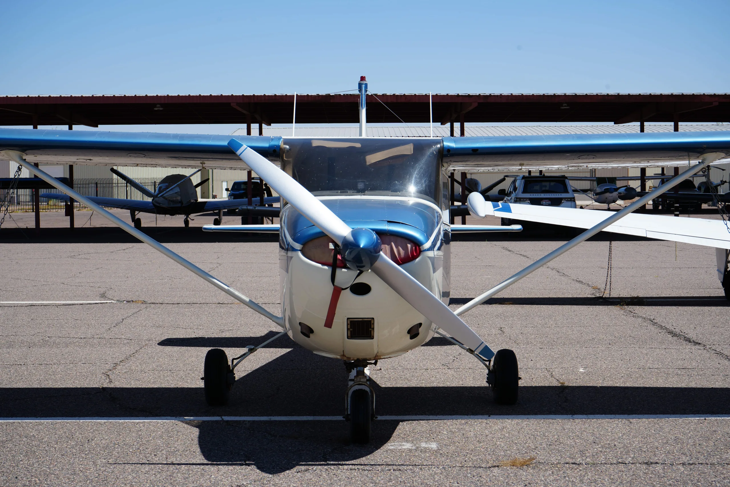
Free — save the 172C to your watchlist and track it in one place.
More CESSNA 172Cmanuals & documents
See all 29 →- Approved Model List For ETX900-TSO Battery InstallationType Certificate
- Service Bulletin SB-12Service Bulletins
- Special Inspection Policy ManualTraining Manual
- CRIMINAL OFFENDER RECORD INFORMATION (C.O.R.I.)Other Documents
- FAA Approved Airplane Flight Manual Supplement for Aerocet Model 2200 Seaplane Float Installation on Cessna Model 172 to 172P and F172D to F172P with Tricycle GearFlight Manual
- Aircraft Weight and Balance ControlPilot's Operating Handbook
- APPROVED MODEL LIST (AML) SA02594SE FOR INSTALLATION OF THE SKYVIEW HDX INSTRUMENTATION AND AUTOPILOT SYSTEMFlight Manual
- SUPPLEMENTAL TYPE CERTIFICATE - 10059692 REV. 1Supplemental Type Certificate
- HAWAII ARMY NATIONAL GUARD (HIARNG) BUILDING 621 RENOVATION AND LATRINE IMPROVEMENTSSpecifications
- Best Glide Speed and DistanceOther Documents
- SUPPLEMENTAL TYPE CERTIFICATE 10051939Supplemental Type Certificate
- Single Engine Service Bulletin SEB07-5 Revision 6, Pilot and Copilot Secondary Seat Stop InstallationService Bulletins
If you fly the CESSNA 172C, you may also be researching these.


In this document
V-Speeds Overview
This section provides a comprehensive list of V-speeds for the Cessna 172C, including Vso (stalling speed in landing configuration), Vs1 (stalling speed in a specified configuration), Vx (best angle of climb speed), Vy (best rate of climb speed), and other critical speeds necessary for flight operations.
Stalling Speeds
The stalling speeds are crucial for understanding the aircraft's performance limits. For the Cessna 172C, Vso is 47 knots, and Vs1 is 50 knots. These speeds indicate the minimum airspeed at which the aircraft can maintain controlled flight.
Takeoff and Landing Speeds
The document specifies the recommended takeoff speed (Vr) as 55 knots and the landing approach speed (Vref) as 65 knots. These speeds are vital for ensuring safe takeoff and landing operations.
Climb Speeds
For optimal climb performance, Vx is noted as 62 knots and Vy as 74 knots. These speeds should be adhered to during the climb phase to achieve the best performance.
Emergency Procedures
In case of an emergency, the document outlines the recommended airspeeds for various scenarios, ensuring pilots are prepared for unexpected situations.
Safety notes
- Always adhere to the specified V-speeds to ensure safe flight operations.
- Monitor airspeed closely during critical phases of flight such as takeoff and landing.
Full document text
CESSNA MORE PEOPLE BUY AND FLY CESSNA AIRPLANES THAN ANY OTHER MAKE MODEL 172 AND SKYHAWK 1969 WORLD'S LARGEST PRO. DUCER OF GENERAL AVIATION AIRCRAFT SINCE 1956 OWNER'S MANUAL PERFORMANCE SPECIFICATIONS Model 172* Skyhawk GROSS WEIGHT SPEED: 2300 lbs 2300 lbs Top Speed at Sea Level . 139 mph 140 mph Cruise, 75% Power at 9000 ft 131 mph 132 mph RANGE: Cruise, 75% Power at 9000 ft 38 Gal. No Reserve 615 miles 620 miles 4.7 hours 4.7 hours 131 mph Cruise, 75% Power at 9000 ft 48 Gal. No Reserve Optimum Range at 10,000 ft. 38 Gal. No Reserve Optimum Range at 10,000 ft 48 Gal. No Reserve RATE OF CLIMB AT SEA LEVEL 775 miles 5.9 hours 132 mph 780 miles 5.9 hours 131 mph 640 miles 132 mph 655 miles 5.5 hours 5.5 hours 117 mph 820 miles 118 mph 830 miles • 7.0 hours 117 mph ⋅ SERVICE CEILING TAKE-OFF: . Ground Run Total Distance Over 50-Foot Obstacle. LANDING: Landing Roll. EMPTY WEIGHT (Approximate) BAGGAGE. . . WING LOADING: Pounds/Sq Foot POWER LOADING: Pounds/HP FUEL CAPACITY: Total Standard Tanks. . Optional Long Range Tanks OIL CAPACITY: Total . . PROPELLER: Fixed Pitch (Diameter) ENGINE: Lycoming Engine Total Distance Over 50-Foot Obstacle. 1250 ft . . 1245 lbs 120 lbs 13.2 645 fpm . 13,100 ft 865 ft 1525 ft 520 ft 7.0 hours 118 mph 645 fpm 13,100 ft 865 ft 1525 ft 520 ft 1250 ft 1315 lbs 120 lbs 13.2 15.3 15.3 42 gal. 42 gal. 52 gal. 52 gal. 8 qts 8 qts 76 inches 76 inches 150 rated HP at 2700 RPM. 0-320-E2D 0-320-E2D *This manual covers operation of the Model 172/Skyhawk which is certificated as Model 172K under FAA Type Certificate No. 3A12. D625-13-RAND-1500-1/74 CONGRATULATIONS • Welcome to the ranks of Cessna owners! Your Cessna has been designed and constructed to give you the most in performance, economy, and com- fort. It is our desire that you will find flying it, either for business or pleasure, a pleasant and profitable experience. This Owner's Manual has been prepared as a guide to help you get the most pleasure and utility from your Model 172/Skyhawk. It contains in- formation about your Cessna's equipment, operating procedures, and per- formance; and suggestions for its servicing and care. We urge you to read it from cover to cover, and to refer to it frequently. Our interest in your flying pleasure has not ceased with your purchase of a Cessna. World-wide, the Cessna Dealer Organization backed by the Cessna Service Department stands ready to serve you. The following services are offered by most Cessna Dealers: FACTORY TRAINED PERSONNEL to provide you with courteous expert service. FACTORY APPROVED SERVICE EQUIPMENT to provide you with the most efficient and accurate workmanship possible. A STOCK OF GENUINE CESSNA SERVICE PARTS on hand when you need them. THE LATEST AUTHORITATIVE INFORMATION FOR SERV- ICING CESSNA AIRPLANES, since Cessna Dealers have all of the Service Manuals and Parts Catalogs, kept current by Service Letters and Service News Letters, published by Cessna Aircraft Company. We urge all Cessna owners to use the Cessna Dealer Organization to the fullest. A current Cessna Dealer Directory accompanies your new airplane. The Directory is revised frequently, and a current copy can be obtained from your Cessna Dealer. Make your Directory one of your cross-country flight planning aids; a warm welcome awaits you at every Cessna Dealer. i ii 26'-11" PRINCIPAL DIMENSIONS 6'-4" MAX. 8'-4" 11'-4" 36'-2" *8-94" MAX. * Maximum height of airplane with nose gear depressed and an optional flashing beacon installed. TABLE OF CONTENTS :Page= SECTION I - OPERATING CHECK LIST . 1-1 SECTION II - DESCRIPTION AND OPERATING DETAILS SECTION III - OPERATING LIMITATIONS .... SECTION IV- CARE OF THE AIRPLANE OWNER FOLLOW-UP SYSTEM SECTION V - OPERATIONAL DATA 2-1 3-1 4-1 4-10 5-1 SECTION VI- OPTIONAL SYSTEMS ………………………………………………… 6-1 ALPHABETICAL INDEX Index-1 This manual describes the operation and performance of both the Cessna Model 172 and Skyhawk. Equipment des - cribed as "Optional" denotes that the subject equipment is optional on the Model 172. Much of this equipment is stan- dard on the Skyhawk model. iii iv 4 6. (3 EXTERIOR INSPECTION 2 Note Visually check fuel filler caps, inspection plates, and general aircraft condi- tion during walk-around inspection. If night flight is planned, check operation of all lights, and make sure a flashlight is available. a. Turn on master switch and check fuel quan- b. tity indicators, then turn master switch off. Check ignition switch "OFF". c. d. Check fuel selector valve handle on "BOTH". Remove control wheel lock. a possibility that the fuel tank sumps contain water. Thus, the fuel tank sump drain plugs and fuel line drain plug should be removed to check for the presence of water. c. e. Check baggage door for security. Check propeller and spinner for nicks and security. d. Check nose wheel strut and tire for proper inflation. (2) a. b. Remove rudder gust lock, if installed. Disconnect tail tie-down. e. Disconnect tie-down rope. 1. Inspect airspeed static source hole on side of fuselage for stoppage (left side only). (3) il. b. == 4 a. b. Disconnect wing tie-down. Check main wheel tire for proper inflation. Check oil level. Do not operate with less than six quarts. Fill for extended flight. Before first flight of day and after each re- fueling, pull out strainer drain knob for about four seconds to clear fuel strainer of possible water and sediment. Check strainer drain closed. If water is observed, there is 5 a. c. Remove pitot tube cover, if installed, and check pitot tube opening for stoppage. b. Check fuel tank vent opening for stoppage. Check stall warning vent opening for stoppage. (6) Same as (3) Figure 1-1. Section I OPERATING CHECK LIST One of the first steps in obtaining the utmost performance, service, and flying enjoyment from your Cessna is to familiarize yourself with your airplane's equipment, systems, and controls. This can best be done by reviewing this equipment while sitting in the airplane. Those items
Show full textShow less
whose function and operation are not obvious are covered in Section II. Section I lists, in Pilot's Check List form, the steps necessary to operate your airplane efficiently and safely. It is not a check list in its true form as it is considerably longer, but it does cover briefly all of the points that you should know for a typical flight. The flight and operational characteristics of your airplane are normal in all respects. There are no "unconventional" characteristics or opera- tions that need to be mastered. All controls respond in the normal way within the entire range of operation. All airspeeds mentioned in Sections I and II are indicated airspeeds. Corresponding calibrated airspeed may be obtained from the Airspeed Correction Table in Section V. BEFORE ENTERING THE AIRPLANE. (1) Make an exterior inspection in accordance with figure 1-1. BEFORE STARTING THE ENGINE. (1) Seats and Seat Belts (2) Fuel Selector (3) Brakes -- -- -- Adjust and lock. "BOTH." Test and set. (4) Radios and Flashing Beacon -- "OFF." 1-1 STARTING THE ENGINE. (1) Mixture -- Rich. (2) Carburetor Heat (3) Primer -- -- - Cold. · 2 – 6 strokes (as required; none if engine is warm). Close and lock primer. (4) Throttle (5) -- Open 1/8". Master Switch (6) Propeller Area (7) Ignition Switch (8) Oil Pressure - - -- -- -- "ON." Clear. · "START" (release when engine starts). Check. BEFORE TAKE-OFF. (1) Parking Brake (2) Cabin Doors -- (3) Flight Controls -- -- Set. Closed and locked. -- - Check. (4) Trim Tab "TAKE-OFF" setting. (5) Throttle Setting 1700 RPM. (6) Engine Instruments and Ammeter -- Check. (7) Suction Gage · Check (4.6 to 5.4 inches of mercury). (8) Carburetor Heat (9) Magnetos -- -- Check operation. - Check (RPM drop should not exceed 125 RPM on either magneto or 50 RPM differential between magnetos). (10) Flight Instruments and Radios (11) Optional Autopilot or Wing Leveler TAKE-OFF. NORMAL TAKE-OFF. (1) Wing Flaps -- -0° -- Cold. (2) Carburetor Heat (3) Power -- · Full throttle. (4) Elevator Control -- -- · Set. -- Off. - Lift nosewheel at 60 MPH. (5) Climb Speed 85 MPH. -- MAXIMUM PERFORMANCE TAKE-OFF. 1-2 (1) Wing Flaps - 0°. -- (2) Carburetor Heat Cold. -- (3) Brakes -- Apply. (4) Power -- Full throttle. (5) Brakes · Release. -- (6) Airplane Attitude (7) Climb Speed -- Slightly tail low. 68 MPH until all obstacles are cleared. CLIMB. NORMAL CLIMB. (1) Airspeed 80 to 90 MPH. (2) Power (3) Mixture -- -- -- Full throttle. Full rich (mixture may be leaned above 5000 feet). MAXIMUM PERFORMANCE CLIMB. (1) Airspeed (2) Power (3) Mixture -- -->> -- - 82 MPH at sea level to 79 MPH at 10,000 feet. Full throttle. Full rich (mixture may be leaned above 5000 feet). CRUISING. (1) Power 2200 to 2700 RPM. NOTE Maximum cruise RPM varies with altitude. For details, refer to Section V. (2) Trim Tab (3) Mixture -- -- Adjust. · Lean for maximum RPM. LET-DOWN. (1) Mixture Rich. -- (2) Power As desired. -- (3) Carburetor Heat -- As required to prevent carburetor icing. 1-3 BEFORE LANDING. (1) Fuel Selector (2) Mixture -- -- - Rich. "BOTH." -- Apply full heat before closing throttle. As desired. (3) Carburetor Heat (4) Wing Flaps (5) Airspeed. -- -- 70 to 80 MPH (flaps up), 65 to 75 MPH (flaps down). BALKED LANDING (GO-AROUND). (1) Power Full throttle. (2) Carburetor Heat · Cold. -- (3) Wing Flaps Retract to 20°. (4) Upon reaching an airspeed of approximately 65 MPH, retract flaps slowly. NORMAL LANDING. (1) Touchdown (2) Landing Roll - Main wheels first. -- · Lower nosewheel gently. (3) Braking Minimum required. AFTER LANDING. (1) Wing Flaps -- Up. (2) Carburetor Heat -- Cold. SECURE AIRCRAFT. (1) Mixture -- Idle cut-off (pulled full out). Off. (2) All switches (3) Brakes -- Set. (4) Control Lock Installed. -- 1-4 MODIFIED FUEL MANAGEMENT PROCEDURES With a combination of highly volatile fuel, high fuel temperature, high operating altitude, and low fuel flow rate in the tank outlet lines, there is a remote possibility of accumulating fuel vapor and encountering power ir- regularities on some airplanes. To minimize this possibility, the follow- ing operating procedures are recommended: (1) Take-off and climb to cruise altitude on "both" tanks. (This is consistent with current recommendations.) (2) When reaching cruise altitude above 5000 feet MSL, promptly switch the fuel selector valve from "both" tanks to either the "right" or "left" tank. (3) During cruise, use "left" and "right" tank as required. (4) Select "both" tanks for landing as currently recommended. POWER RECOVERY TECHNIQUES In the remote event that vapor is present in sufficient amounts to cause a power irregularity, the following power recovery techniques should be followed: OPERATION ON A SINGLE TANK Should power irregularities occur when operating on a single tank, power can be restored immediately by switching to the opposite tank. In addition, the vapor accumulation in the tank on which the power irregu- larity occurred will rapidly dissipate itself such that that tank will also be available for normal operation after it has been unused for approximately one (1) minute. OPERATION ON BOTH TANKS Should power irregularities occur with the fuel selector on both tanks, the following steps are to be taken to restore power: (1) Switch to a single tank for a period of 60 seconds. (2) Then switch to the opposite tank and power will be restored. 1-5 INSTRUMENT PANEL 2 7 8 9 10 11 12 00000 орзова 33 32 31 30 29 28 27 26 25 24 21 23- 22 22 20 19 18 17 16 15 14 13 12345 Flight Instrument Group 13. Optional Instrument Space 24. Throttle Compass Correction Card (Typical) 25. 3. Aircraft Registration Number 14. Map Compartment 26. 4. Magnetic Compass 15. 5. Rear View Mirror (Opt.) Carburetor Air Temperature Gage (Opt.) 27. Circuit Breakers 28. 6. Radio Selector Switches (Opt.) 16. Wing Flap Position Indicator 29. Phone Jack 7. Marker Beacon Indicator Lights 17. Cigar Lighter 30. and Switches (Opt.) 18. Cabin Air and Heat Controls 31. 8. Radios (Opt.) 19. Wing Flap Switch Carburetor Air Heat Control Electrical Switches Parking Brake Handle Ignition/Starter Switch Static Pressure Alternate Source Valve (Opt.) 9. Tachometer 20. Mixture Control Knob 32. Master Switch 10. Ammeter 21. Autopilot Control Unit (Opt.) 33. Primer 11. Suction Gage (Opt.) 22. Microphone 12. Fuel and Oil Gages 23. Elevator Trim Control Wheel 1-6 Figure 2-1. Section II DESCRIPTION AND OPERATING DETAILS The following paragraphs describe the systems and equipment whose function and operation is not obvious when sitting in the airplane. This section also covers in somewhat greater detail some of the items listed in Check List form in Section I that require further explanation. FUEL SYSTEM. Fuel is supplied to the engine from two tanks, one in each wing. With the fuel selector valve on "BOTH," the total usable fuel for all flight con- ditions is 38 gallons for the standard tanks and 48 gallons for the optional long range tanks. Fuel from each wing tank flows by gravity to a selector valve. De- pending upon the setting of the selector valve, fuel from the left, right, or both tanks flows through a fuel strainer and carburetor to the engine induction system. IMPORTANT The fuel selector valve should be in the "BOTH" position for take-off, climb, landing, and maneuvers that involve prolonged slips or skids. Operation from either "LEFT" or "RIGHT" tank is reserved for cruising flight. NOTE When the fuel selector valve handle is in the "BOTH" position in cruising flight, unequal fuel flow from each tank may occur if the wings are not maintained exactly level. Resulting wing heaviness can be alleviated gradually by turning the selector valve handle to the tank in the "heavy" wing. For fuel system servicing information, refer to Lubrication and Servicing Procedures in Section IV. 2-1 VENT FUEL SYSTEM SCHEMATIC LEFT FUEL TANK SO FACH & LANDMţa || SELECTOR VALVE TO ENGINE ENGINE PRIMER FUEL STRAINER CODE FUEL SUPPLY RIGHT FUEL TANK VENT 100 THROTTLE MECHANICAL LINKAGE CARBURETOR TO • ENGINE 2-2 Figure 2-2. MIXTURE CONTROL KNOB ELECTRICAL SYSTEM. Electrical energy is supplied by a 14-volt, direct-current system powered by an engine-driven alternator (see figure 2-3). A 12- volt bat- tery is located on the left-hand forward portion of the firewall. Power is supplied to all electrical circuits through a split bus bar, one side con- taining electronic systems and the other side having general electrical systems. Both sides of the bus are on at all times except when either an external power source is connected or the ignition/starter switch is turned on; then a power contactor is automatically activated to open the circuit to the electronic bus. Isolating the electronic circuits in this manner pre- vents harmful transient voltages from damaging the transistors in the electronic equipment. AMMETER. The ammeter indicates the flow of current, in amperes, from the alternator to the battery or from the battery to the aircraft electrical system. When the engine is operating and the master switch is "ON," the ammeter indicates the charging rate applied to the battery. In the event the alternator is not functioning or the electrical load exceeds the output of the alternator, the ammeter indicates the discharge rate of the battery. CIRCUIT BREAKERS AND FUSES. The majority of electrical circuits in the airplane are protected by "push-to-reset" circuit breakers mounted on the instrument panel. Ex- ceptions to this are the optional clock, flight hour recorder, and battery contactor closing (external power) circuits which have fuses mounted adjacent to the battery. Also, the cigar lighter is protected by a man- ually reset type circuit breaker mounted directly on the back of the lighter behind the instrument panel. The alternator field and wiring is protected by an automatically resetting circuit breaker. LANDING LIGHTS (OPT). A three-position, push-pull switch controls the optional landing lights. To turn one lamp on for taxiing, pull the switch out to the first stop. To turn both lamps on for landing, pull the switch out to the sec- ond stop. To turn both lamps off, push the switch full in. 2-3
What's in the CESSNA 172C TCDS
A Type Certificate Data Sheet (TCDS) is the FAA's record of what an aircraft type was approved as. It is the source of truth for weights, seating, fuel and the rules the design was certified against. Expand any line to see what it means.
43 CESSNA 172C parts for sale
See all →




Parts listed for sale by vetted eBay sellers — confirmed on eBay at checkout.