Weight & Balance for Cessna 175
CESSNA 175 · Weight And Balance
Overview
This document provides essential information regarding the weight and balance specifications for the Cessna 175 aircraft. It is intended for pilots, flight planners, and maintenance personnel who need to ensure that the aircraft is loaded within its weight limits for safe operation. The document outlines the maximum weight capacities, center of gravity limits, and procedures for calculating weight and balance before flight. Proper adherence to these guidelines is crucial for maintaining aircraft performance and safety during operations.
- Maximum takeoff weight: 2,400 lbs
- Forward CG limit: 34.0 inches
- Aft CG limit: 39.0 inches
- Weight calculation involves summing individual weights and moments
- Proper loading is essential for flight safety
Document
Source
Originally published by hasslo.org. Sprinkle hosts a reference copy with an added summary, specifications and searchable full text.
Document details
- Type
- Weight And Balance
- Pages
- 23
- File size
- 2.7 MB
- Publisher
- hasslo.org
Specifications & performance
Extracted from this document.
Specifications
- Propeller
- MCCAULEY
- Engine model
- LYCOMING 0-320-H2AD
- Empty weight (lb)
- 1,454
- Fuel capacity (gal)
- 40
- Max takeoff weight (lb)
- 2,300
Weight & balance
- Max ramp weight (lb)
- 2,307
- Baggage allowance (lb)
- 120
- Basic empty weight (lb)
- 1,454
- Max landing weight (lb)
- 2,300
- Max takeoff weight (lb)
- 2,300
Common. One of the most common aircraft types we track.
Most owners only have the POH. Here's the essential set for the CESSNA 175.
- Pilot's Operating Handbook / AFM
- Checklist
- Maintenance Manual
- Parts Catalog (IPC)
- Systems & Wiring
- Service Bulletins
- Type Certificate (TCDS)
CESSNA 175 for sale now

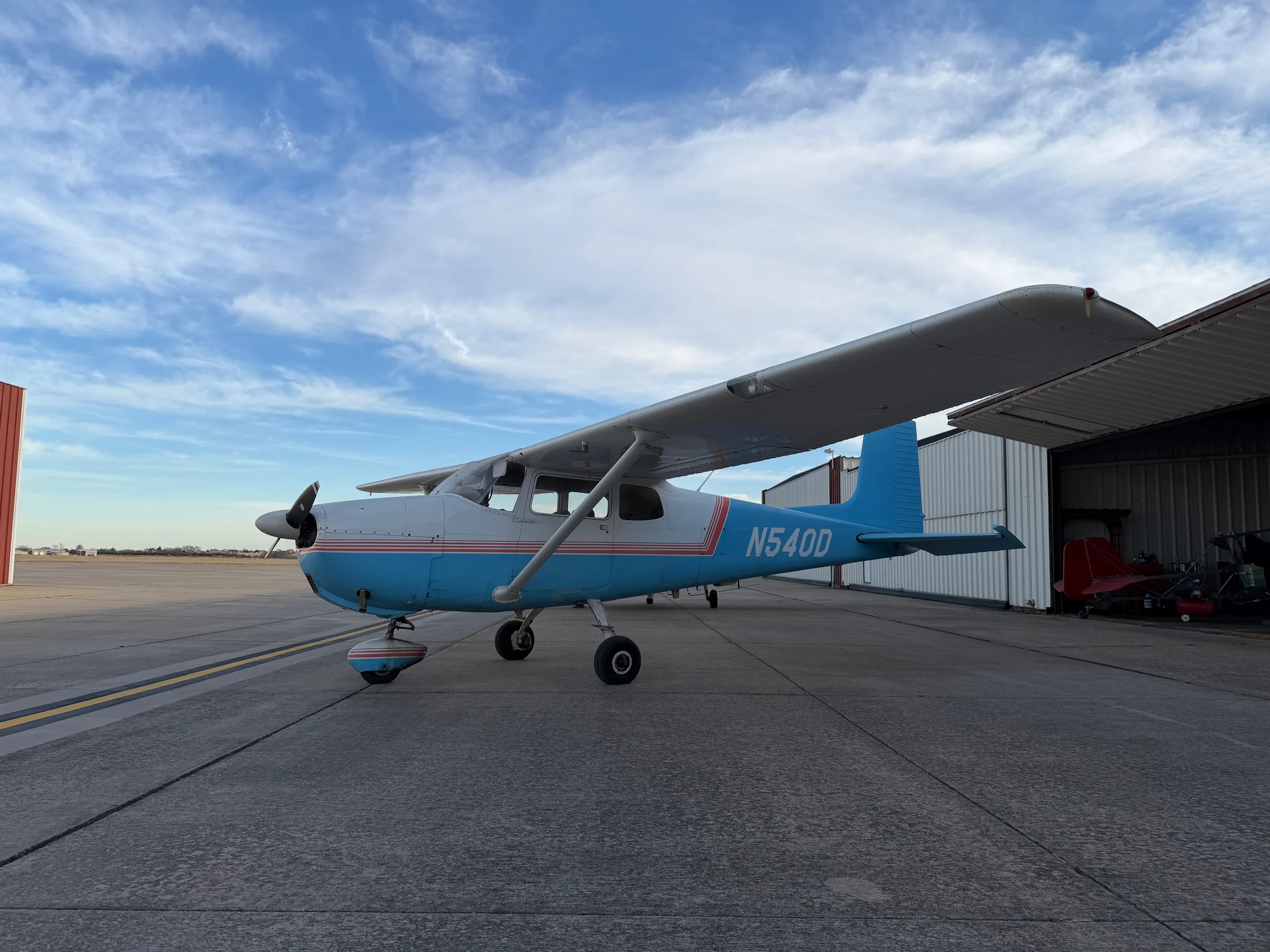
Free — save the 175 to your watchlist and track it in one place.
More CESSNA 175manuals & documents
- PARTS MANUAL FOR WIPLINE MODEL 2100 FLOATS ON CESSNA 172 & 175Wiring Diagram
- PARTS MANUAL FOR WIPLINE MODEL 2350 FLOATS ON CESSNA 172 & 175 SERIESWiring Diagram
- SERVICE LETTER 228Service Manual
- Vizion Install Appendix C C175/C172Wiring Diagram
- Cessna FlyerChecklist
- Airworthiness Directive Schedule Aeroplanes Cessna 175 SeriesService Bulletins
- Airworthiness Directives; CESSNA Models 140A, 150, A150, 170, 172, 175, P172D, R172, 177, 180, 182, 185, A185, 188, A188, 205, 206, U206, TU206, P206, TP206, 207, T207, 210, T210, 336, 337, T337, M337B Series AirplanesAirworthiness Directives
- PART 39— AIRWORTHINESS DIRECTIVES Cessna Series AirplanesAirworthiness Directives
- 1958 Cessna 175 SpecificationsSpecifications
- Instructions for Continued AirworthinessSystems Description
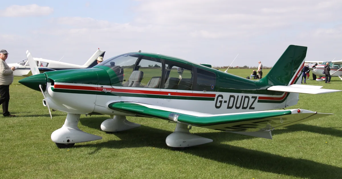
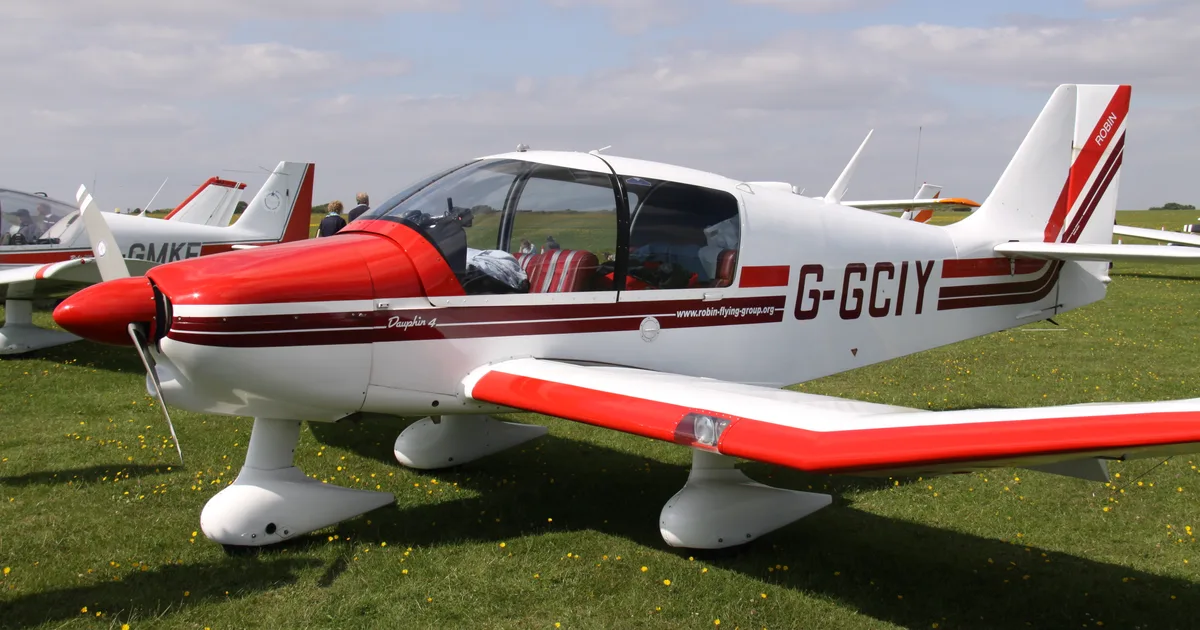
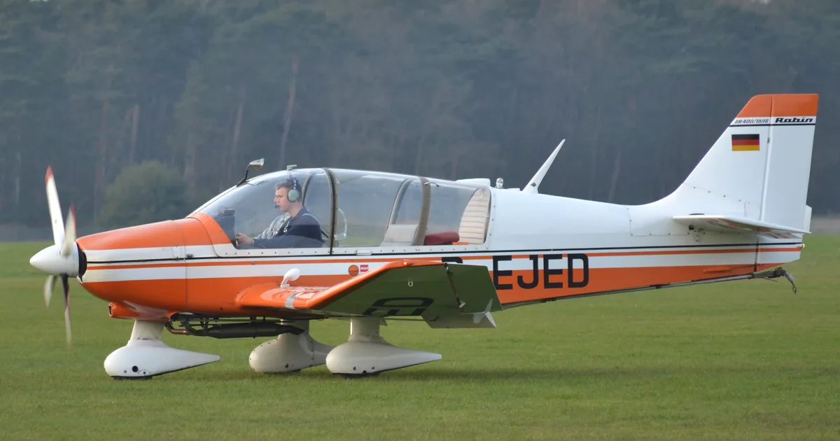
If you fly the CESSNA 175, you may also be researching these.


In this document
Maximum Weight Limits
The maximum takeoff weight for the Cessna 175 is 2,400 lbs. This includes the weight of the aircraft, passengers, cargo, and fuel. It is essential to ensure that the total weight does not exceed this limit to maintain safe flight operations.
Center of Gravity Limits
The center of gravity (CG) limits for the Cessna 175 are critical for flight stability. The forward CG limit is 34.0 inches, and the aft CG limit is 39.0 inches from the datum. Proper loading is necessary to keep the CG within these limits.
Weight Calculation Procedures
To calculate the weight and balance, list the weight of each occupant, baggage, and fuel. Use the provided tables to determine the moment for each item and sum these values to find the total weight and moment. Ensure that the total weight and CG are within the specified limits.
Safety notes
- Exceeding weight limits can lead to compromised aircraft performance and safety.
- Improper CG can affect aircraft stability and control.
Full document text
CESSNA MODEL 172N SECTION 6 WEIGHT & BALANCE/ EQUIPMENT LIST SECTION 6 WEIGHT & BALANCE/ EQUIPMENT LIST TABLE OF CONTENTS Introduction. Airplane Weighing Procedures Weight And Balance Equipment List Page 6-3 6-3 6-6 6-13 1 July 1978 6-1/(6-2 blank) CESSNA MODEL 172N SECTION 6 WEIGHT & BALANCE/ EQUIPMENT LIST INTRODUCTION This section describes the procedure for establishing the basic empty weight and moment of the airplane. Sample forms are provided for reference. Procedures for calculating the weight and moment for various operations are also provided. A comprehensive list of all Cessna equip- ment available for this airplane is included at the back of this section. It should be noted that specific information regarding the weight, arm, moment and installed equipment list for this airplane can only be found in the appropriate weight and balance records carried in the airplane. It is the responsibility of the pilot to ensure that the airplane is loaded properly. AIRPLANE WEIGHING PROCEDURES 1. Preparation: a. Inflate tires to recommended operating pressures. b. Remove the fuel tank sump quick-drain fittings and fuel selector valve drain plug to drain all fuel. C. d. Remove oil sump drain plug to drain all oil. Move sliding seats to the most forward position. e. Raise flaps to the fully retracted position. Place all control surfaces in neutral position. f. 2. Leveling: a. Place scales under each wheel (minimum scale capacity, 500 pounds nose, 1000 pounds each main). b. Deflate the nose tire and/or lower or raise the nose strut to properly center the bubble in the level (see figure 6-1). 3. Weighing: a. With the airplane level and brakes released, record the weight shown on each scale. Deduct the tare, if any, from each reading. 4. Measuring: a. Obtain measurement A by measuring horizontally (along the airplane center line) from a line stretched between the main wheel centers to a plumb bob dropped from the firewall. b. Obtain measurement B by measuring horizontally and paral- lel to the airplane center line, from center of nose wheel axle, left side, to a plumb bob dropped from the line between the main wheel centers. Repeat on right side and average the measure- ments. 5. Using weights from item 3 and measurements from item 4, the airplane weight and C.G. can be determined. 6. Basic Empty Weight may be determined by completing figure 6-1. 1 July 1978 6-3 SECTION 6 WEIGHT & BALANCE/ EQUIPMENT LIST Datum Sta. 0.0 (Firewall, Front Face, Lower Portion) CESSNA MODEL 172N C.G. Level at upper door sill or leveling screws on left side of tailcone. B N L & R Scale Position Scale Reading Tare Symbol Net Weight Left Wheel L Right Wheel Nose Wheel Sum of Net Weights (As Weighed) R N W X = ARM = (A) - (N) × (B) ; X = ( W )-( )x( ) = ( ) IN. Item Moment/1000 Weight (Lbs.) X C.G. Arm (In.) = = (Lbs.-In.) Airplane Weight (From Item 5, page 6-3) Add Oil: No Oil Filter (6 Qts at 7.5 Lbs/Gal) With Oil Filter (7 Qts at 7.5 Lbs/Gal) Add Unusable Fuel: Std. Tanks (3 Gal at 6 Lbs/Gal) L.R. Tanks (4 Gal at 6 Lbs/Gal). Equipment Changes Airplane Basic Empty Weight -14.0 -14.0 46.0 46.0 Figure 6-1. Sample Airplane Weighing 6-4 1 July 1978 B 1 July 1978 A N MODEL 172N CESSNA SAMPLE WEIGHT AND BALANCE RECORD (Continuous History of Changes in Structure or Equipment Affecting Weight and Balance) AIRPLANE MODEL SERIAL NUMBER PAGE NUMBER WEIGHT CHANGE ITEM NO. RUNNING BASIC EMPTY WEIGHT ADDED (+) DATE DESCRIPTION REMOVED (-) OF ARTICLE OR MODIFICATION Wt. In Out (lb.) Arm Moment Wt. (In.) /1000 (lb.) (In.) Arm Moment /1000 Wt. Moment (lb.) /1000 6-5 SECTION 6 EQUIPMENT LIST WEIGHT & BALANCE/ Figure 6-2. Sample Weight and Balance Record SECTION 6 WEIGHT & BALANCE/ EQUIPMENT LIST WEIGHT AND BALANCE CESSNA MODEL 172N The following information will enable you to operate your Cessna within the prescribed weight and center of gravity limitations. To figure weight and balance, use the Sample Problem, Loading Graph, and Center of Gravity Moment Envelope as follows: Take the basic empty weight and moment from appropriate weight and balance records carried in your airplane, and enter them in the column titled YOUR AIRPLANE on the Sample Loading Problem. NOTE In addition to the basic empty weight and moment noted on these records, the C.G. arm (fuselage station) is also shown, but need not be used on the Sample Loading Problem. The moment which is shown must be divided by 1000 and this value used as the moment/1000 on the loading problem. Use the Loading Graph to determine the moment/1000 for each additional item to be carried; then list these on the loading problem. NOTE Loading Graph information for the pilot, passengers and baggage is based on seats positioned for average occu- pants and baggage loaded in the center of the baggage areas as shown on the Loading Arrangements diagram. For loadings which may differ from these, the Sample Loading Problem lists fuselage stations for these items to indicate their forward and aft C.G. range limitations (seat travel and baggage area limitation). Additional moment calculations, based on the actual weight and C.G. arm (fuselage station) of the item being loaded, must be made if the position of the load is different from that shown on the Loading Graph. Total the weights and moments/1000 and plot these values on the Center of Gravity Moment Envelope to determine whether the point falls within the envelope, and if the loading is acceptable. 6-6 1 July 1978 S 00 CESSNA MODEL 172N LOADING ARRANGEMENTS STATION (C.G. ARM), *37 *Pilot or passenger center of gravity on adjustable seats positioned for average occupant. Numbers in paren- theses indicate forward and aft limits of occupant center of gravity range. **Arm measured to the center of the areas shown. NOTE: The rear cabin wall (approximate station 108) or aft baggage wall (approximate station 142) can be used as convenient interior reference points for determining the location of baggage area fuselage stations. (34 TO 46) SECTION 6
Show full textShow less
WEIGHT & BALANCE/ EQUIPMENT LIST STATION (C.G. ARM), PILOT PASS. *37 (34 TO 41) PILOT PASS. REAR PASS. REAR PASS. 73 73 BAGGAGE **95 96 CHILD SEAT AREA 1 108 108 BAGGAGE BAGGAGE ** ** 123 *123 AREA 2 AREA 2 142 142 STANDARD SEATING OPTIONAL SEATING Figure 6-3. Loading Arrangements 1 July 1978 6-7 SECTION 6 WEIGHT & BALANCE/ EQUIPMENT LIST FIREWALL CABIN HEIGHT MEASUREMENTS CESSNA MODEL 172N AFT BAGGAGE AREA 48" 43" 33" 1014" -484" 65¼". 65.3 ·42¾" 34"- DOOR OPENING DIMENSIONS WIDTH WIDTH HEIGHT HEIGHT (TOP) (BOTTOM) (FRONT) (REAR) WIDTH: LWR WINDOW LINE CABIN DOOR BAGGAGE DOOR 32" 15¼" 37" 15¼" 40" 22'' 41" 21: * CABIN FLOOR CABIN WIDTH MEASUREMENTS INSTRUMENT PANEL REAR DOORPOST BULKHEAD • 38½" 392" • 37½" 35" 33½" 1 1 I 21½" * 34" *29½" 25" * 28" *36" 142 CABIN STATIONS O 10 20 30 40 50 60 70 80 90 100 110 120 130 140 (C.G. ARMS) 65.3 6-8 Figure 6-4. Internal Cabin Dimensions 1 July 1978 1 July 1978 SAMPLE LOADING PROBLEM CESSNA MODEL 172N SAMPLE AIRPLANE YOUR AIRPLANE Weight (lbs.) Moment (lb. -ins. /1000) Moment Weight (lbs.) (lb. - ins. ./1000) 11.5 A 1. Basic Empty Weight (Use the data pertaining to your airplane as it is presently equipped. Includes unusable fuel and full oil) 1454 57.6 2. Usable Fuel (At 6 Lbs./Gal.) Standard Tanks (40 Gal. Maximum) 240 11.5 Long Range Tanks (50 Gal. Maximum) 3. Pilot and Front Passenger (Station 34 to 46) 340 12.6 4. Rear Passengers 170 12.4 5. * Baggage Area 1 or Passenger on Child's Seat (Station 82 to 108, 120 Lbs. Max.) 103 9.8 " * 6. Baggage Area 2 (Station 108 to 142, 50 Lbs. Max.). 7. RAMP WEIGHT AND MOMENT 2307 103.9 8. Fuel allowance for engine start, taxi, and runup -7 -.3 9. TAKEOFF WEIGHT AND MOMENT (Subtract Step 8 from Step 7) 2300 103.6 10. Locate this point (2300 at 103.6) on the Center of Gravity Moment Envelope, and since this point falls within the envelope, the loading is acceptable. 6-9 SECTION 6 WEIGHT & BALANCE/ EQUIPMENT LIST * The maximum allowable combined weight capacity for baggage areas 1 and 2 is 120 lbs. Figure 6-5. Sample Loading Problem 6-10 1 July 1978 LOAD WEIGHT (POUNDS) LOAD MOMENT/1000 (KILOGRAM-MILLIMETERS) 0 50 100 150 200 250 300 350 400 200 400 350 300 250 200 150 LOADING GRAPH 50 GAL**. (189,3 LITRES). PILOT & FRONT PASSENGER FUEL (6 LBS/GAL; 0,72 KG/LITRE) 40 GAL* (151,4 LITRES)- 30 (113,6) 100 50 0 10 (37,9), 20 (75,7) BAGGAGE AREA 2- PASSENGER ON CHILD'S SEAT BAGGAGE AREA 1 OR NOTE: REAR PASSENGERS, 175 I 150 125 100 75 50 MAXIMUM USABLE FUEL 500 *STANDARD TANKS **LONG RANGE TANKS 10 15 20 20 25 25 LOAD MOMENT/1000 (POUND - INCHES) 30 30 Line representing adjustable seats shows the pilot or passenger center of gravity on adjustable seats positioned for an average occupant. Refer to the Loading Arrangements diagram for forward and aft limits of occupant C.G. range. Figure 6-6. Loading Graph SECTION 6 EQUIPMENT LIST WEIGHT & BALANCE/ LOAD WEIGHT (KILOGRAMS) 25 25 0 میں ممان MODEL 172N CESSNA 1 July 1978 5000 منون 6-11 2300 2200 2100 LOADED AIRPLANE WEIGHT (POUNDS) 2000 1900 1800 1700 1600 LOADED AIRPLANE MOMENT/1000 (KILOGRAM-MILLIMETERS) 600 700 800 900 1000 1100 1200 1300 CENTER OF GRAVITY MOMENT ENVELOPE UTILITY CATEGORY 1050 1000 NORMAL CATEGORY 950 900 850 CESSNA MODEL 172N LOADED AIRPLANE WEIGHT (KILOGRAMS) 800 750 700 1500 45 50 55 60 65 70 75 80 85 90 95 100 105 110 LOADED AIRPLANE MOMENT/1000 (POUND-INCHES) Figure 6-7. Center of Gravity Moment Envelope SECTION 6 WEIGHT & BALANCE/ EQUIPMENT LIST 6-12 1 July 1978 2300 2200 2100 LOADED AIRPLANE WEIGHT (POUNDS) AIRPLANE C.G. LOCATION - MILLIMETERS AFT OF DATUM (STA. 0.0) 875 900 925 950 975 1000 1025 1050 1075 1100 1125 1150 1175 1200 2000 1900 1800 1700 UTILITY CATEGORY 1600 CENTER OF GRAVITY LIMITS 1050 1000 950 900 SECTION 6 EQUIPMENT LIST WEIGHT & BALANCE/ LOADED AIRPLANE WEIGHT (KILOGRAMS) 850 800 NORMAL CATEGORY 750 700 1500 34 35 36 37 38 39 40 41 42 43 44 45 46 47 2 AIRPLANE C.G. LOCATION - INCHES AFT OF DATUM (STA. 0.0) Figure 6-8. Center of Gravity Limits MODEL 172N CESSNA CESSNA MODEL 172N SECTION 6 WEIGHT & BALANCE/ EQUIPMENT LIST EQUIPMENT LIST The following equipment list is a comprehensive list of all Cessna equipment available for this airplane. A separate equipment list of items installed in your specific airplane is provided in your aircraft file. The following list and the specific list for your airplane have a similar order of listing. This equipment list provides the following information: An item number gives the identification number for the item. Each number is prefixed with a letter which identifies the descriptive grouping (exam- ple: A. Powerplant & Accessories) under which it is listed. Suffix letters identify the equipment as a required item, a standard item or an optional item. Suffix letters are as follows: -R = required items of equipment for FAA certification -S = standard equipment items -O= optional equipment items replacing required or standard items -A = optional equipment items which are in addition to required or standard items A reference drawing column provides the drawing number for the item. NOTE If additional equipment is to be installed, it must be done in accordance with the reference drawing, accessory kit instruc- tions, or a separate FAA approval. Columns showing weight (in pounds) and arm (in inches) provide the weight and center of gravity location for the equipment. NOTE Unless otherwise indicated, true values (not net change values) for the weight and arm are shown. Positive arms are distances aft of the airplane datum; negative arms are distan- ces forward of the datum. NOTE Asterisks (*) after the item weight and arm indicate complete assembly installations. Some major components of the assem- bly are listed on the lines immediately following. The summa- tion of these major components does not necessarily equal the complete assembly installation. 1 July 1978 6-13 SECTION 6 EQUIPMENT LIST WEIGHT & BALANCE/ MODEL 172N CESSNA ITEM NO A01-R A05-R A09-R A17-R A21-A A33-R A33-0 A41-R A61-S VACUUM GAUGE A70-A EQUIPMENT LIST DESCRIPTION A. POWERPLANT & ACCESSORIES EN GINE, LYCOMING 0-320-H2AD (INCLUDES ELECTRIC STARTER, VACUUM PUMP PAD, SPARK PLUGS & CARBURETOR FILTER, CARBURETOR AIR ALTERNATOR, 28 VOLT, 60 AMP (BELT DRIVE) OIL COOLER INSTALLATION O IL COOL ER OIL FILTER INSTALLATION ( SPIN-ON ELEMENT) NET CHANGE PROPELLER ASSY. (FIXED PITCH-LAND PLANE) PROP ELL ER (MCCAULEY) 3.5 INCH PROP SPACER ADAPTOR (MCCAULEY) PROPELL ER ASSY. (FIXED PITCH-FLOATPLANE ) PROP ELLER (MCCAULEY) 3.5 INCH PROP SPACER ADAPTOR ( MCCAULEY) SP INNER INSTALLATION, PROPELLER SPINNER DOME FWD SP INNER BULKHEAD AFT SPINNER BULKHEAD VACUUM SYSTEM INSTALLATION DRY VACUUM PUMP FILTER RELIEF VALVE-REGULATOR PRIMER SYSTEM, ENGINE THREE CYLINDER REF DRAWING WT LBS ARM INS 0550333 C294510-0301 C611503-0102 0550333 10599 A 0501060 C161001-0310 1C160/DTM7557 C161001-0307 NN111 -2.5* -2.5 6.5 38.5* 39.1 269.5* -19.7* 10.7 2.5* 2. 2.5 1 1 35.9* 30.1 C4516 3.6 -35.4 37.5* .38.6* 1 A175/ETM8042 31.8 39.1 C4516 306 35.4 05503 20 2.0* 41.4* 0550236 -8 1.2 43.1 0550321-4 0.3 40.8 0550321-10 0.4 37.3 0501054 -2.7* 0431003-0101 -6.3 1201075-2 0.2 5.4 C668509-0101 0.1 16.7 C482001-0401 Ο 5.0 A73-A DIL QUICK DRAIN VALVE ( NET CHANGE) 0501056-1 1701015 -12.0 B. LANDING GEAR & ACCESSORIES B01-R WHEEL, BRAKE & TIRE ASSY, 6.00X6 MAIN (2) WHEEL ASSY, MCCAULEY C163018-0201 C163005-0101 41.7* 57.8* 7.8 58.2 BRAKE ASSY., MCCAULEY (LEFT) 0163032-0115 1.9 54.5 BRAKE ASSY., MCCAULEY (RIGHT) C163032-0114 1.9 54.5 TIRE, 4-PLY BLACKWALL (EACH) C252003-0101 8.5 58.2 TUBE (EACH) C262023-0102 1.8 58.2 B04-R WHEEL & TIRE ASSY., 5.00X5 NO SE WHEEL ASSY., MCCAULEY C163018-0101 8.7* * C163005-0201 6-14 1 July 1978 MODEL 172N CESSNA SECTION 6 EQUIPMENT LIST WEIGHT & BALANCE/ ITEM NO EQUIPMENT LIST DESCRIPTION REF DRAWING WT LBS ARM INS TIRE, 4-PLY BLACKWALL TUBE 810-S FAIRING INSTALLATION, WHEEL NOSE WHEEL FAIRING (SET OF 3) 0262003-0102 C262023-0101 0541225-1 MAIN WHEEL FAIRING (EACH) 49745 400 5.7 12827 -409 60.3 88888 146 66740 C. ELECTRICAL SYSTEMS Col-R BATTERY, 24 VOLT, STANDARD DUTY 0614001-0105 22.8 C01-0 BATTERY, 24 VOLT, HEAVY DUTY C6140010106 24.8 C04-R ALTERNATOR CONTROL UNIT, 28 VOLT WITH HIGH 0611004-0101 004 .0 9:3 005 LOW VOLTAGE SENSING C07-A C16-0 GROUND SERVICE PLUG RECEPTACLE HEATING SYSTEM, PITOT (NET CHANGE) 0501064 2.7 0422355 0.6 C22-A LIGHTS, INSTRUMENT POST (REQUIRES INSTALL- ATION OF E34-0 DELUXE GLARESHIELD) 0513094 0.5 122 240 C 25-A C28-S LIGHT, MAP (CONTROL WHEEL MTD, RQS E89-0) LIGHT, MAP & INSTRUMENT PANEL FLOOD (DOCRPOST MOUNTED) 0570087 0.2 0700149 22:3 21° 32.0 645 C31-A LIGHTS, COURTESY ENTRANCE (SET OF 2) 0521101 0.5 61.0 040-A C43-A DETECTORS, NAVIGATION LIGHT (SET OF 2) LIGHT INSTALLATION, OMNIFLASH BEACON BEACON LIGHT ON FIN TIP FLASHER POWER SUPPLY RESISTOR (MEMCCR) 0701013-1, -2 NEG 0506003 184.2* 0621001-0102 243.0 C594502-0102 205.8 C46-A 049-S 649-0 LIGHT INSTALLATION, WING TIP STROBE FLASHER POWER SUPPLY (SET OF 2 IN WING) STROBE LIGHT, WING TIP (SET OF 2) LIGHT INSTALLATION, COWL MOUNTED LANDING LAMP, 250 WATT (G.E.) OR95-6 0501027 208. 43.3* C622008-0102 0622006-0101 0570312 1.9* 4553 0.8 0552141 3.2* 4591 0.5 1 | | 1 47.0 43.5 27.1* 29.0 3.0* 29.0 1 July 1978 LIGHTS, DUAL COWL MOUNTED LANDING LAMP, 250 WATT (G.E.) (EACH) D INSTRUMENTS 001-R 001-0 INDICATOR, AIRSPEED 0661064-0102 0.6 16.2 INDICATOR, TRUE AIRSPEED 0513279 0.7 16.3 004-A STATIC AIR ALTERNATE SCURCE 0501017 0.2 15.5 6-15
What's in the CESSNA 175 TCDS
A Type Certificate Data Sheet (TCDS) is the FAA's record of what an aircraft type was approved as. It is the source of truth for weights, seating, fuel and the rules the design was certified against. Expand any line to see what it means.
597 CESSNA 175 parts for sale
See all →

Parts listed for sale by vetted eBay sellers — confirmed on eBay at checkout.