Airplane Flying Handbook (FAA-H-8083-3C) - Chapter 13
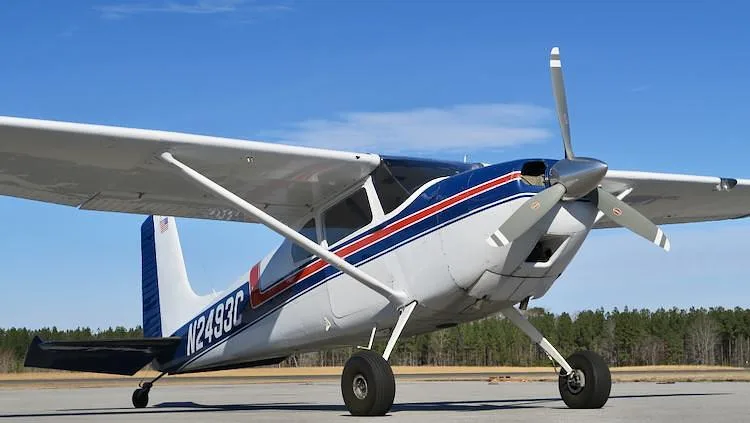
CESSNA 180 · Training Manual
Overview
The document is the Airplane Flying Handbook (FAA-H-8083-3C), which serves as a comprehensive guide for pilots transitioning to multiengine airplanes. It covers the unique operational characteristics of small multiengine aircraft, particularly those with a maximum takeoff weight of 12,500 pounds or less. The handbook emphasizes the importance of understanding one-engine inoperative (OEI) flight, highlighting the differences in performance and control compared to single-engine aircraft. It provides essential information on V-speeds specific to multiengine operations, risk management strategies, and the necessity for proper training and proficiency. The document is intended for pilots and flight instructors, serving as a reference for safe multiengine flying practices.
- Maximum certificated takeoff weight for small multiengine airplanes is 12,500 pounds or less.
- VYSE is marked with a blue radial line on airspeed indicators and is crucial for OEI operations.
- Loss of thrust from one engine can reduce climb performance by 80 to 90 percent.
- Feathering propellers minimizes drag from an inoperative engine, aiding in control.
- Fuel crossfeed systems allow for fuel management between wings in multiengine aircraft.
Document
Source
Originally published by www.faa.gov. Sprinkle hosts a reference copy with an added summary, specifications and searchable full text.
Document details
- Type
- Training Manual
- Pages
- 37
- File size
- 16 MB
- Publisher
- www.faa.gov
Common. One of the most common aircraft types we track.
Most owners only have the POH. Here's the essential set for the CESSNA 180.
CESSNA 180 for sale now


Free — save the 180 to your watchlist and track it in one place.
More CESSNA 180manuals & documents
See all 33 →- Instructions For Continued Airworthiness - Hartzell PropellerMaintenance Manual
- SEB-34-33-Stall-Warning-Horn-180-185-188.pdfParts Catalog
- AD 2020-21-22 - McFarlane AviationAirworthiness Directives
- Airworthiness Directive Schedule - Cessna 180 Series - CAAAirworthiness Directives
- Type Acceptance Report TAR 99/11 — Cessna 180 SeriesOther Documents
- airfilm camera systems report afwm-1-006 installation instructions ...Weight And Balance
- Vizion Install Appendix E C180, C182-C182D, C185Wiring Diagram
- V-Speeds ReferenceOther Documents
- Over-wing Fuel Tank Vent Systems (Including Early Cessna 180 ...Service Bulletins
- CESSNA, 180, 182, Skylane, 185, Skywagon, Exhaust System.Systems Description
- ALERT SERVICE BULLETIN - Hartzell PropellerService Bulletins
- AD/CESSNA 180/89 - Crew Seat Back Cylinder Lock ModificationService Bulletins
If you fly the CESSNA 180, you may also be researching these.


In this document
Introduction
This section introduces the concept of small multiengine airplanes, defining them as those with a maximum takeoff weight of 12,500 pounds or less. It discusses the operational differences between multiengine and single-engine aircraft, particularly in terms of engine failure and the importance of pilot training.
V-Speeds
The document outlines several critical V-speeds for multiengine aircraft, including VR (rotation speed), VLOF (lift-off speed), VX (best angle of climb speed), and VY (best rate of climb speed). It also introduces OEI-specific speeds such as VXSE and VYSE, which are crucial for understanding performance during engine failure.
Engine Failure and Performance
This section details the impact of engine failure on aircraft performance, noting that the loss of thrust from one engine can significantly reduce climb performance and create control challenges. It emphasizes the need for pilots to be aware of these factors to ensure safe operation.
Feathering Propellers
The handbook explains the feathering process for propellers on multiengine aircraft, which minimizes drag from an inoperative engine. It describes the mechanics of feathering and the importance of this feature for maintaining control and performance after an engine failure.
Crossfeed Systems
This section discusses fuel crossfeed systems unique to multiengine airplanes, which allow an engine to draw fuel from the opposite wing's tank. It outlines the operational procedures and checks necessary to ensure proper functionality of the crossfeed system.
Safety notes
- Attention to engine failure procedures is crucial for safe OEI flight.
- Proper training and proficiency are essential for multiengine operations.
- Always consult the AFM/POH for specific operational procedures.
Full document text
Airplane Flying Handbook (FAA-H-8083-3C) Chapter 13: Transition to Multiengine Airplanes Introduction This chapter is devoted to the factors associated with the operation of small multiengine airplanes. For the purpose of this handbook, a “small” multiengine airplane is a reciprocating or turbopropeller-powered airplane with a maximum certificated takeoff weight of 12,500 pounds or less. This discussion assumes a conventional design with two engines—one mounted on each wing. Reciprocating engines are assumed unless otherwise noted. The term “light-twin,” although not formally defined in the regulations, is used herein as a small multiengine airplane with a maximum certificated takeoff weight of 6,000 pounds or less. There are several unique characteristics of multiengine airplanes that make them worthy of a separate class rating. The one engine inoperative (OEI) flight information presented in this chapter emphasizes the significant difference between flying a multiengine and a single-engine airplane. However, all pilots need appropriate knowledge, risk management strategies, and skills to fly safely in any airplane they fly, and mastery of OEI flight is only one aspect of safe multiengine flying. The modern, well-equipped multiengine airplane can be remarkably capable under many circumstances, but, the performance and system redundancy of a multiengine airplane only increase safety if the pilot is trained and proficient. The airplane manufacturer is the final authority on the operation of a particular make and model airplane. Flight instructors and learners should use the Federal Aviation Administration’s Approved Flight Manual (AFM) and/or the Pilot’s Operating Handbook (POH). The airplane manufacturer’s guidance and procedures take precedence over any general recommendations made in this handbook. General Multiengine and single-engine airplanes operate differently during an engine failure. In a multiengine airplane, loss of thrust from one engine affects both performance and control. The most obvious problem is the loss of 50 percent of power, which reduces climb performance 80 to 90 percent. In some cases after an engine failure, the ability to climb or maintain altitude in a light-twin may not exist. After an engine failure, asymmetrical thrust also creates control issues for the pilot. Attention to both these factors is crucial to safe OEI flight. Terms and Definitions Pilots of single-engine airplanes are already familiar with many performance “V” speeds and their definitions. Twin-engine airplanes have several additional V-speeds unique to OEI operation. These speeds are differentiated by the notation “SE” for single engine. A review of some key V-speeds and several new V-speeds unique to twin-engine airplanes are listed below. ⦁ VR—rotation speed—speed at which back pressure is applied to rotate the airplane to a takeoff attitude. ⦁ VLOF—lift-off speed—speed at which the airplane leaves the surface. (Note: Some manufacturers reference takeoff performance data to V R , others to VLOF .) ⦁ VX—best angle of climb speed—speed at which the airplane gains the greatest altitude for a given distance of forward travel. ⦁ VXSE—best angle-of-climb speed with OEI. ⦁ V Y—best rate of climb speed—speed at which the airplane gains the most altitude for a given unit of time. ⦁ VYSE—best rate of climb speed with OEI. Marked with a blue radial line on most airspeed indicators. Above the single-engine absolute ceiling, V YSE yields the minimum rate of sink. ⦁ VSSE—safe, intentional OEI speed—originally known as safe single-engine speed. It is the minimum speed to intentionally render the critical engine inoperative. ⦁ VREF—reference landing speed—an airspeed used for final approach, which is normally 1.3 times VSO , the stall speed in the landing configuration. The pilot may adjust the approach speed for winds and gusty conditions by using V REF plus an additional number of units (e.g.,VREF+5). 13-1 ⦁ VMC—currently defined in 14 CFR part 23, section 23.2135(c) as the calibrated airspeed at which, following the sudden critical loss of thrust, it is possible to maintain control of the airplane. VMC is typically marked with a red radial line on most airspeed indicators [Figure 13-1]. VMC was previously defined in 14 CFR part 23, section 23.149 as the calibrated airspeed at which, when the critical engine is suddenly made inoperative, it is possible to maintain control of the airplane with that engine still inoperative, and thereafter maintain straight flight at the same speed with an angle of bank of not more than 5 degrees. This definition still applies to airplanes certified under that regulation. There is no requirement under either determination that the airplane be capable of climbing at this airspeed. VMC only addresses directional control. Further discussion of VMC as determined during airplane certification and demonstrated in pilot training follows later in this chapter. Figure 13-1. Airspeed indicator markings for a multiengine airplane Unless otherwise noted, when V-speeds are given in the AFM/POH, they apply to sea level, standard day conditions at maximum takeoff weight. Performance speeds vary with aircraft weight, configuration, and atmospheric conditions. The speeds may be stated in statute miles per hour (mph) or knots (kt), and they may be given as calibrated airspeeds (CAS) or indicated airspeeds (IAS). As a general rule, the newer AFM/POHs show V-speeds in knots indicated airspeed (KIAS). Some V-speeds are also stated in knots calibrated airspeed (KCAS) to meet certain regulatory requirements. Whenever available, pilots should operate the airplane from published indicated airspeeds. Rate of climb is the altitude gain per unit of time, while climb gradient is the actual measure of altitude gained per 100 feet of horizontal travel, expressed as a percentage. An altitude gain of 1.5 feet per 100 feet of travel (or 15 feet per 1,000 or 150 feet per
Show full textShow less
10,000) is a climb gradient of 1.5 percent. 13-2 There is a dramatic performance loss associated with the loss of an engine, particularly just after takeoff. Any airplane’s climb performance is a function of thrust horsepower, which is in excess of that required for level flight. In a hypothetical twin with each engine producing 200 thrust horsepower, assume that the total level flight thrust horsepower required is 175. In this situation, the airplane would ordinarily have a reserve of 225 thrust horsepower available for climb. Loss of one engine would leave only 25 (200 minus 175) thrust horsepower available for climb, a drastic reduction. The performance characteristics of an airplane depend upon the rules in effect during type certification and do not depend on the production year after certification. The current amendment to 14 CFR part 23, 81 FR 96689, went into effect on December 30, 2016. This includes certification of normal category airplanes with passenger seating configuration of 19 or less and a maximum certificated takeoff weight of 19,000 pounds or less (section 23.2005(a)). Current 14 CFR part 23 certification rules (section 23.2005(b)) classify airplanes into certification levels 1 through 4 based on maximum passenger seating configuration. For example, a level 2 airplane has a passenger seating configuration between two and six passengers. The rule further divides airplanes into two different performance levels based on speed (section 23.2005(c)). After a critical loss of thrust, a level 2 low speed airplane (V NO or V MO less than or equal to 250 knots calibrated airspeed and M MO less than or equal to 0.6) that does not meet single-engine crashworthiness requirements requires a climb gradient of at least 1.5 percent at a pressure altitude of 5,000 feet in the cruise configuration for certification (section 23.2120(b)(1)). While, the various subsets of airplanes receiving certification under the current part 23 meet specific single-engine climb performance criteria as listed in 14 CFR part 23, section 23.2120(b), the historical 14 CFR part 23 single-engine climb performance requirements for reciprocating engine-powered multiengine airplanes are broken down as follows: ⦁ More than 6,000 pounds maximum weight and/or VSO more than 61 knots: the single-engine rate of climb in feet per minute (fpm) at 5,000 feet mean sea level (MSL) must be equal to at least 0.027 V SO 2. For airplanes type certificated February 4, 1991, or thereafter, the climb requirement is expressed in terms of a climb gradient, 1.5 percent. The climb gradient is not a direct equivalent of the .027 V SO 2 formula. Do not confuse the date of type certification with the airplane’s model year. The type certification basis of many multiengine airplanes dates back to the Civil Aviation Regulations (CAR) 3. ⦁ 6,000 pounds or less maximum weight and VSO 61 knots or less: the single-engine rate of climb at 5,000 feet MSL must simply be determined. The rate of climb could be a negative number. There is no requirement for a single-engine positive rate of climb at 5,000 feet or any other altitude. For light-twins type certificated February 4, 1991, or thereafter, the single-engine climb gradient (positive or negative) is simply determined. Operation of Systems This section deals with systems and equipment that are generally installed in multiengine airplanes. Multiengine airplanes share many features with complex single-engine airplanes. However, there are certain features that are found more often in airplanes with two or more engines. Feathering Propellers Although the propellers of a multiengine airplane may appear identical to a constant-speed propeller used in many single-engine airplanes, this is usually not the case. The pilot of a typical multiengine airplane can feather the propeller of an inoperative engine. Since it stops engine rotation with the propeller blade streamlined with the airplane’s relative wind, feathering the propeller of an inoperative engine minimizes propeller drag. [Figure 13-2] Depending upon single-engine performance, this feature often permits continued flight to a suitable airport following an engine failure. Feathering is important because of the change in parasite drag with propeller blade angle. [Figure 13-3] When the propeller blade angle is in the feathered position, parasite drag from the propeller is at a minimum. In a typical multiengine airplane, the parasite drag from a single, feathered propeller is a small part the airplane's total drag. At the smaller blade angles near the flat pitch position, the drag added by the propeller is large. At these small blade angles, the propeller windmilling at high revolutions per minute (rpm) can create enough drag to make the airplane difficult or impossible to control. A propeller windmilling at high speed in the low range of blade angles can produce parasite drag as great as the parasite drag of the entire airframe. 13-3 Figure 13-2. Feathered propeller. 13-4 Figure 13-3. Propeller drag contribution. As a review, the constant-speed propellers on almost all single-engine airplanes are of the non-feathering, oil-pressure-to-increase- pitch design. In this design, increased oil pressure from the propeller governor drives the blade angle towards high pitch, low rpm. In contrast, the constant-speed propellers installed on most multiengine airplanes are full feathering, counterweighted, oil-pressure-to- decrease-pitch designs. In this design, increased oil pressure from the propeller governor drives the blade angle toward low pitch, high rpm—away from the feather blade angle. In effect, the only thing that keeps these propellers from feathering is a constant supply of high-pressure engine oil. This is a necessity to enable propeller feathering in the event of a loss of oil pressure or a propeller governor failure. Aerodynamic forces acting upon a windmilling propeller tend to drive the blades to low pitch, high rpm. Counterweights attached to the shank of each blade tend to force the blades to high pitch, low rpm. Inertia, or the apparent force (called centrifugal force) acting through the counterweights, is generally slightly greater than the aerodynamic forces. Therefore, centrifugal force would drive the blades to high pitch and low rpm were it not for an additional force acting through the propeller governor. A controlling force generated from high pressure oil from the propeller governor pushes the propeller blade angles toward low pitch and high rpm. Thus, a reduction in oil pressure allows the counterweights to drive the blades to a higher pitch and decreases engine rpm. [Figure 13-4] To feather the propeller, the propeller control is brought fully aft. All oil pressure is dumped from the governor, and the counterweights drive the propeller blades toward feather. As centrifugal force acting on the counterweights decays from decreasing rpm, additional forces are needed to completely feather the blades. This additional force comes from either a spring or high-pressure air stored in the propeller dome, which forces the blades into the feathered position. The entire process may take up to 10 seconds. 13-5 Figure 13-4. Pitch change forces. Feathering a propeller only alters blade angle and stops engine rotation. To completely secure the engine, the pilot turns off the fuel (mixture, electric boost pump, and fuel selector), ignition, alternator/generator, and closes the cowl flaps. If the airplane is pressurized, there may also be an air bleed to close for the failed engine. Some airplanes are equipped with firewall shutoff valves that secure several of these systems with a single switch. Completely securing a failed engine may not be necessary or even desirable depending upon the failure mode, altitude, and time available. The position of the fuel controls, ignition, and alternator/generator switches of the failed engine has no effect on aircraft performance, and the pilot might manipulate the incorrect switch under conditions of haste or pressure. To unfeather a propeller, the engine should be rotated so that oil pressure can be generated to move the propeller blades from the feathered position. The ignition is turned on prior to engine rotation with the throttle at low idle and the mixture rich. With the propeller control in a high rpm position, the starter is engaged. The engine begins to windmill, start, and run as oil pressure moves the blades out of feather. As the engine starts, the propeller rpm should be immediately reduced until the engine has had several minutes to warm up; the pilot should monitor cylinder head and oil temperatures. An unfeathering accumulator is a device that permits starting a feathered engine in-flight without the use of the electric starter. An accumulator is any device that stores a reserve of high pressure. On multiengine airplanes, the unfeathering accumulator stores a small reserve of engine oil under pressure from compressed air or nitrogen. To start a feathered engine in-flight, the pilot moves the propeller control out of the feather position to release the accumulator pressure. The oil flows under pressure to the propeller hub and drives the blades toward the high rpm, low pitch position, whereupon the propeller usually begins to windmill. If fuel and ignition are present, the engine starts and runs. High oil pressure from the propeller governor recharges the accumulator just moments after engine rotation begins making it available for another unfeathering cycle, if needed. For airplanes used in training, an unfeathering accumulator may prolong the life of the electric starter and battery. If the accumulator fails to bring the propeller out of feather, the electric starter may be engaged. 13-6 In any event, the AFM/POH procedures should be followed for the exact unfeathering procedure. Both feathering and starting a feathered reciprocating engine on the ground are strongly discouraged by manufacturers due to the excessive stress and vibrations generated. As just described, a loss of oil pressure from the propeller governor allows the counterweights, spring, and/or dome charge to drive the blades to feather. Logically then, the propeller blades should feather every time an engine is shut down as oil pressure falls to zero. However, below approximately 800 rpm, a reduction in centrifugal force allows small anti-feathering lock pins in the pitch changing mechanism of the propeller hub to move into place and block feathering. Therefore, if a propeller is to be feathered, it needs to be done before engine rpm decays below approximately 800. On one popular model of turboprop engine, the propeller blades do, in fact, feather with each shutdown. This propeller is not equipped with such centrifugally-operated pins due to a unique engine design. Propeller Synchronization Many multiengine airplanes have a propeller synchronizer (prop sync) installed to eliminate the annoying “drumming” or “beat” of propellers whose rpm are close, but not precisely the same. To use prop sync, the propeller rpms are coarsely matched by the pilot and the system is engaged. The prop sync adjusts the rpm of the “slave” engine to precisely match the rpm of the “master” engine and then maintains that relationship. The prop sync should be disengaged when the pilot selects a new propeller rpm and then re-engaged after the new rpm is set. The prop sync should always be off for takeoff, landing, and single-engine operation. The AFM/POH should be consulted for system description and limitations. A variation on the propeller synchronizer is the propeller synchrophaser. A propeller synchrophaser acts much like a synchronizer to precisely match rpm, but the synchrophaser goes one step further. It not only matches rpm but actually compares and adjusts the positions of the individual blades of the propellers in their arcs. There can be significant propeller noise and vibration reductions with a propeller synchrophaser. From the pilot’s perspective, operation of a propeller synchronizer and a propeller synchrophaser are very similar. A synchrophaser is also commonly referred to as prop sync, although that is not entirely correct nomenclature from a technical standpoint. As a pilot aid to manually synchronizing the propellers, some twins have a small gauge mounted in or by the tachometer(s) with a propeller symbol on a disk that spins. The pilot manually fine tunes the engine rpm so as to stop disk rotation, thereby synchronizing the propellers. This is a useful backup to synchronizing engine rpm using the audible propeller beat. This gauge is also found installed with most propeller synchronizer and synchrophase systems. Some synchrophase systems use a knob for the pilot to control the phase angle. Fuel Crossfeed Fuel crossfeed systems are also unique to multiengine airplanes. Using crossfeed, an engine can draw fuel from a fuel tank located in the opposite wing. On most multiengine airplanes, operation in the crossfeed mode is an emergency procedure used to extend airplane range and endurance in OEI flight. There are a few models that permit crossfeed as a normal, fuel balancing technique in normal operation, but these are not common. The AFM/POH describes crossfeed limitations and procedures that vary significantly among multiengine airplanes. Checking crossfeed operation on the ground with a quick repositioning of the fuel selectors does nothing more than ensure freedom of motion of the handle. To actually check crossfeed operation, a complete, functional crossfeed system check should be accomplished. To do this, each engine should be operated from its crossfeed position during the run-up. The engines should be checked individually and allowed to run at moderate power (1,500 rpm minimum) for at least 1 minute to ensure that fuel flow can be established from the crossfeed source. Upon completion of the check, each engine should be operated for at least 1 minute at moderate power from the main (takeoff) fuel tanks to reconfirm fuel flow prior to takeoff. This suggested check is not required prior to every flight. Crossfeed lines are ideal places for water and debris to accumulate unless they are used from time to time and drained using their external drains during preflight. Crossfeed is ordinarily not used for completing a flight with one engine inoperative when an alternate airport is nearby. Pilots should never use crossfeed during takeoff or for normal landing operations with both engines operating. A landing with one engine inoperative using crossfeed may be necessary if setting normal fuel flow would cause the operative engine to fail. 13-7 Combustion Heater Combustion heaters are another common item on multiengine airplanes not found on single-engine airplanes. A combustion heater is best described as a small furnace that burns gasoline to produce heated air for occupant comfort and windshield defogging. Most are thermostatically operated and have a separate hour meter to record time in service for maintenance purposes. Automatic over- temperature protection is provided by a thermal switch mounted on the unit that cannot be accessed in flight. This requires the pilot or mechanic to visually inspect the unit for possible heat damage in order to reset the switch. Manufacturers often suggest a cool-down period when shutting down a combustion heater. Most heater instructions recommend that outside air be permitted to circulate through the unit for at least 15 seconds in flight or that the ventilation fan can be operated for at least 2 minutes on the ground. Failure to provide an adequate cool down usually trips the thermal switch and renders the heater inoperative until the switch is reset. Flight Director/Autopilot Multiengine airplanes are often equipped with flight director/autopilot (FD/AP) systems. The system integrates pitch, roll, heading, altitude, and radio navigation signals in a computer. The outputs, called computed commands, are displayed on a flight command indicator (FCI). The FCI replaces the conventional attitude indicator on the instrument panel. The FCI is occasionally referred to as a flight director indicator (FDI) or as an attitude director indicator (ADI). The entire flight director/autopilot system is called an integrated flight control system (IFCS) by some manufacturers. Others may use the term automatic flight control system (AFCS). The FD/AP system may be employed at the following different levels: ⦁ Off (raw data) ⦁ Flight director (computed commands) ⦁ Autopilot With the system off, the FCI operates as an ordinary attitude indicator. On most FCIs, the command bars are biased out of view when the FD is off. The pilot maneuvers the airplane as though the system were not installed. To maneuver the airplane using the FD, the pilot enters the desired modes of operation (heading, altitude, navigation (NAV) intercept, and tracking) on the FD/AP mode controller. The computed flight commands are then displayed to the pilot through either a single-cue or dual-cue system in the FCI. On a single-cue system, the commands are indicated by “V” bars. On a dual-cue system, the commands are displayed on two separate command bars, one for pitch and one for roll. To maneuver the airplane using computed commands, the pilot “flies” the symbolic airplane of the FCI to match the steering cues presented. On most systems, the FD needs to be operating to engage the autopilot. At any time thereafter, the pilot may engage the autopilot through the mode controller. The autopilot then maneuvers the airplane to satisfy the computed commands of the FD. Like any computer, the FD/AP system only does what it is told. The pilot should ensure that it has been programmed properly for the particular phase of flight desired. The armed and/or engaged modes are usually displayed on the mode controller or separate annunciator lights. When the airplane is being hand-flown, if the FD is not being used at any particular moment, it should be off so that the command bars are pulled from view. Prior to system engagement, all FD/AP computer and trim checks should be accomplished. Many newer systems cannot be engaged without the completion of a self-test. The pilot should also be familiar with various methods of disengagement, both normal and emergency. System details, including approvals and limitations, can be found in the supplements section of the AFM/POH. Additionally, many avionics manufacturers can provide informative pilot operating guides upon request. Yaw Damper The yaw damper is a servo that moves the rudder in response to inputs from a gyroscope or accelerometer that detects yaw rate or lateral Gs, respectively. The yaw damper reduces motion about the vertical axis caused by turbulence. (Yaw dampers on swept wing airplanes provide another, more vital function of damping Dutch roll characteristics.) Occupants feel a smoother ride, particularly if seated in the rear of the airplane, when the yaw damper is engaged. The yaw damper should be off for takeoff and landing. There may be additional restrictions against its use with one engine inoperative. Most yaw dampers can be engaged independently of the autopilot. 13-8 Alternator/Generator On a multiengine aircraft, each engine has an alternator or generator installed. Alternator or generator paralleling circuitry matches the output of each engine’s alternator/generator so that the electrical system load is shared equally between them. In the event of an alternator/generator failure, the inoperative unit can be isolated and the entire electrical system powered from the remaining one. Depending upon the electrical capacity of the alternator/generator, the pilot may need to reduce the electrical load (referred to as load shedding) when operating on a single unit. The AFM/POH contains system description and limitations. Nose Baggage Compartment Nose baggage compartments are common on multiengine airplanes (and are even found on a few single-engine airplanes). There is nothing strange or exotic about a nose baggage compartment, and the usual guidance concerning observation of load limits applies. Pilots occasionally neglect to secure the latches properly. When improperly secured, the door may open and the contents may be drawn out, usually into the propeller arc and just after takeoff. Even when the nose baggage compartment is empty, airplanes have been lost when the pilot became distracted by the open door. Security of the nose baggage compartment latches and locks is a vital preflight item. Most airplanes continue to fly with a nose baggage door open. There may be some buffeting from the disturbed airflow, and there is an increase in noise. Pilots should never become so preoccupied with an open door (of any kind) that they fail to fly the airplane. Inspection of the compartment interior is another important preflight item. More than one pilot has been surprised to find a supposedly empty compartment packed to capacity or loaded with ballast. The tow bars, engine inlet covers, windshield sun screens, oil containers, spare chocks, and miscellaneous small hand tools that find their way into baggage compartments should be secured to prevent damage from shifting in flight. Anti-Icing/Deicing Equipment Anti-icing/deicing equipment is frequently installed on multiengine airplanes and may consist of a combination of different systems. These may be classified as either anti-icing or deicing, depending upon function. The presence of anti-icing and deicing equipment, even though it may appear elaborate and complete, does not necessarily mean that the airplane is approved for flight in icing conditions. The AFM/POH, placards, and even the manufacturer should be consulted for specific determination of approvals and limitations. Anti-icing equipment is provided to prevent ice from forming on certain protected surfaces. Examples of anti-icing equipment include heated pitot tubes, heated or non-icing static ports and fuel vents, propeller blades with electrothermal boots or alcohol slingers, windshields with alcohol spray or electrical resistance heating, windshield defoggers, and heated stall warning lift detectors. On many turboprop engines, the “lip” surrounding the air intake is heated either electrically or with bleed air. In the absence of AFM/POH guidance to the contrary, anti-icing equipment should be actuated prior to flight into known or suspected icing conditions. Deicing equipment is generally limited to pneumatic boots on wing and tail leading edges. Deicing equipment is installed to remove ice that has already formed on protected surfaces. Upon pilot actuation, the boots inflate with air from the pneumatic pumps to break off accumulated ice. After a few seconds of inflation, they are deflated back to their normal position with the assistance of a vacuum. The pilot monitors the buildup of ice and cycles the boots as directed in the AFM/POH. An ice light on the left engine nacelle allows the pilot to monitor wing ice accumulation at night. Other airframe equipment necessary for flight in icing conditions includes an alternate induction air source and an alternate static system source. Ice tolerant antennas are also installed. In the event of impact ice accumulating over normal engine air induction sources, carburetor heat (carbureted engines) or alternate air (fuel-injected engines) should be selected. Ice buildup on normal induction sources can be detected by a loss of engine rpm with fixed-pitch propellers and a loss of manifold pressure with constant-speed propellers. On some fuel-injected engines, an alternate air source is automatically activated with blockage of the normal air source. An alternate static system provides an alternate source of static air for the pitot-static system in the unlikely event that the primary static source becomes blocked. In non-pressurized airplanes, most alternate static sources are plumbed to the cabin. On pressurized airplanes, they are usually plumbed to a non-pressurized baggage compartment. The pilot may activate the alternate static source by opening a valve or a fitting in the flight deck. Activation may create airspeed indicator, altimeter, or vertical speed indicator (VSI) errors. A correction table is frequently provided in the AFM/POH. 13-9 Anti-icing/deicing equipment only eliminates ice from the protected surfaces. Significant ice accumulations may form on unprotected areas, even with proper use of anti-ice and deice systems. Flight at high angles of attack (AOA) or even normal climb speeds permit significant ice accumulations on lower wing surfaces, which are unprotected. Many AFM/POHs provide minimum speeds to be maintained in icing conditions. Degradation of all flight characteristics and large performance losses can be expected with ice accumulations. Pilots should not rely upon the stall warning devices for adequate stall warning with ice accumulations. Ice accumulates unevenly on the airplane. It adds weight and drag (primarily drag) and decreases thrust and lift. Even wing shape affects ice accumulation; thin airfoil sections are more prone to ice accumulation than thick, highly-cambered sections. For this reason, certain surfaces, such as the horizontal stabilizer, are more prone to icing than the wing. With ice accumulations, landing approaches should be made with a minimum wing flap setting (flap extension increases the AOA of the horizontal stabilizer) and with an added margin of airspeed. Sudden and large configuration and airspeed changes should be avoided. Unless otherwise recommended in the AFM/POH, the autopilot should not be used in icing conditions. Continuous use of the autopilot masks trim and handling changes that occur with ice accumulation. Without this control feedback, the pilot may not be aware of ice accumulation building to hazardous levels. The autopilot suddenly disconnects when it reaches design limits, and the pilot may find the airplane has assumed unsatisfactory handling characteristics. The installation of anti-ice/deice equipment on airplanes without AFM/POH approval for flight into icing conditions is to facilitate escape when such conditions are inadvertently encountered. Even with AFM/POH approval, the prudent pilot avoids icing conditions to the maximum extent practicable and avoids extended flight in any icing conditions. No multiengine airplane is approved for flight into severe icing conditions and none are intended for indefinite flight in continuous icing conditions. Performance and Limitations Discussion of performance and limitations requires the definition of the following terms. ⦁ Accelerate-stop distance is the runway length required to accelerate to a specified speed (either VR or V LOF , as specified by the manufacturer), experience an engine failure, and bring the airplane to a complete stop. [Figure 13-5A] ⦁ Accelerate-go distance is the horizontal distance required to continue the takeoff and climb to 50 feet, assuming an engine failure at V R or V LOF , as specified by the manufacturer. [Figure 13-5A] ⦁ Climb gradient is a slope most frequently expressed in terms of altitude gain per 100 feet of horizontal distance, whereupon it is stated as a percentage. A 1.5 percent climb gradient is an altitude gain of one and one-half feet per 100 feet of horizontal travel. Climb gradient may also be expressed as a function of altitude gain per nautical mile (NM), or as a ratio of the horizontal distance to the vertical distance (10:1, for example). [Figure 13-5B] Unlike rate of climb, climb gradient is affected by wind. Climb gradient is improved with a headwind component and reduced with a tailwind component. Figure 13-5A. Accelerate-stop distance and accelerate-go distance. 13-10 Figure 13-5B. Climb gradient. ⦁ The all-engine service ceiling of multiengine airplanes is the highest altitude at which the airplane can maintain a steady rate of climb of 100 fpm with both engines operating. The airplane has reached its absolute ceiling when climb is no longer possible. ⦁ The single-engine service ceiling is reached when the multiengine airplane can no longer maintain a 50 fpm rate of climb with OEI, and its single-engine absolute ceiling when climb is no longer possible. The takeoff in a multiengine airplane should be planned in sufficient detail so that the appropriate action is taken in the event of an engine failure. The pilot should be thoroughly familiar with the airplane’s performance capabilities and limitations in order to make an informed takeoff decision as part of the preflight planning. That decision should be reviewed as the last item of the “before takeoff” checklist. In the event of an engine failure shortly after takeoff, the decision is basically one of continuing flight or landing, even off-airport. If single-engine climb performance is adequate for continued flight, and the airplane has been promptly and correctly configured, the climb after takeoff may be continued. If single-engine climb performance is such that climb is unlikely or impossible, a landing has to be made in the most suitable area. To be avoided above all is attempting to continue flight when it is not within the airplane’s performance capability to do so. [Figure 13-6] Figure 13-6. Area of decision for engine failure after lift-off. Takeoff planning factors include weight and balance, airplane performance (both single and multiengine), runway length, slope and contamination, terrain and obstacles in the area, weather conditions, and pilot proficiency. Most multiengine airplanes have AFM/POH performance charts and the pilot should be proficient in their use. Prior to takeoff, the multiengine pilot should ensure that the weight and balance limitations have been observed, the runway length is adequate, and the normal flightpath clears obstacles and terrain. The pilot should also consider the appropriate actions expected in the event of an engine failure at any point during the takeoff. 13-11 The regulations do not specifically require that the runway length be equal to or greater than the accelerate-stop distance. Most AFM/POHs publish accelerate-stop distances only as an advisory. It becomes a limitation only when published in the limitations section of the AFM/POH. Experienced multiengine pilots, however, recognize the safety margin of runway lengths in excess of the bare minimum required for normal takeoff, and they insist on runway lengths of at least accelerate-stop distance as a matter of safety and good operating practice. The multiengine pilot considers that under ideal circumstances, the accelerate-go distance only brings the airplane to a point a mere 50 feet above the takeoff elevation. To achieve even this meager climb, the pilot had to instantaneously recognize and react to an unanticipated engine failure, retract the landing gear, identify and feather the correct engine, all the while maintaining precise airspeed control and bank angle as the airspeed is nursed to VYSE. Assuming flawless airmanship thus far, the airplane has now arrived at a point little more than one wingspan above the terrain, assuming it was absolutely level and without obstructions. For the purpose of illustration, with a near 150 fpm rate of climb at a 90-knot VYSE, it takes approximately 3 minutes to climb an additional 450 feet to reach 500 feet AGL. In doing so, the airplane has traveled an additional 5 NM beyond the original accelerate- go distance, with a climb gradient of about 1.6 percent. Any turn, such as to return to the airport, seriously degrades the already marginal climb performance of the airplane. Not all multiengine airplanes have published accelerate-go distances in their AFM/POH and fewer still publish climb gradients. When such information is published, the figures have been determined under ideal flight testing conditions. It is unlikely that this performance is duplicated in service conditions. The point of the previous discussion is to illustrate the marginal climb performance of a multiengine airplane that suffers an engine failure shortly after takeoff, even under ideal conditions. The prudent multiengine pilot should pick a decision point in the takeoff and climb sequence in advance. If an engine fails before this point, the takeoff should be rejected, even if airborne, for a landing on whatever runway or surface lies essentially ahead. If an engine fails after this point, the pilot should promptly execute the appropriate engine failure procedure and continue the climb, assuming the performance capability exists. As a general recommendation, if the landing gear has not been selected up, the takeoff should be rejected, even if airborne. As a practical matter for planning purposes, the option of continuing the takeoff probably does not exist unless the published single- engine rate-of-climb performance is at least 100 to 200 fpm. Thermal turbulence, wind gusts, engine and propeller wear, or poor technique in airspeed, bank angle, and rudder control can easily negate even a 200 fpm rate of climb. A pre-takeoff safety brief clearly defines all pre-planned emergency actions to all crewmembers. Even if operating the aircraft alone, the pilot should review and be familiar with takeoff emergency considerations. Indecision at the moment an emergency occurs degrades reaction time and the ability to make a proper response. Weight and Balance The weight and balance concept is no different than that of a single-engine airplane. The actual execution, however, is almost invariably more complex due to a number of new loading areas, including nose and aft baggage compartments, nacelle lockers, main fuel tanks, auxiliary fuel tanks, nacelle fuel tanks, and numerous seating options in a variety of interior configurations. The flexibility in loading offered by the multiengine airplane places a responsibility on the pilot to address weight and balance prior to each flight. The terms empty weight, licensed empty weight, standard empty weight, and basic empty weight as they appear on the manufacturer’s original weight and balance documents are sometimes confused by pilots. In 1975, the General Aviation Manufacturers Association (GAMA) adopted a standardized format for AFM/POHs. It was implemented by most manufacturers in model year 1976. Airplanes whose manufacturers conform to the GAMA standards utilize the following terminology for weight and balance: standard empty weight + optional equipment = basic empty weight Standard empty weight is the weight of the standard airplane, full hydraulic fluid, unusable fuel, and full oil. Optional equipment includes the weight of all equipment installed beyond standard. Basic empty weight is the standard empty weight plus optional equipment. Note that basic empty weight includes no usable fuel, but full oil. Airplanes manufactured prior to the GAMA format generally utilize the following terminology for weight and balance, although the exact terms may vary somewhat: 13-12 empty weight + unusable fuel = standard empty weight standard empty weight + optional equipment = licensed empty weight Empty weight is the weight of the standard airplane, full hydraulic fluid, and undrainable oil. Unusable fuel is the fuel remaining in the airplane not available to the engines. Standard empty weight is the empty weight plus unusable fuel. When optional equipment is added to the standard empty weight, the result is licensed empty weight. Licensed empty weight, therefore, includes the standard airplane, optional equipment, full hydraulic fluid, unusable fuel, and undrainable oil. The major difference between the two formats (GAMA and the old) is that basic empty weight includes full oil and licensed empty weight does not. Oil should always be added to any weight and balance utilizing a licensed empty weight. When the airplane is placed in service, amended weight and balance documents are prepared by appropriately-rated maintenance personnel to reflect changes in installed equipment. The old weight and balance documents are customarily marked “superseded” and retained in the AFM/POH. Maintenance personnel are under no regulatory obligation to utilize the GAMA terminology, so weight and balance documents subsequent to the original may use a variety of terms. Pilots should use care to determine whether or not oil has to be added to the weight and balance calculations or if it is already included in the figures provided. The multiengine airplane is where most pilots encounter the term “zero fuel weight” for the first time. Not all multiengine airplanes have a zero fuel weight limitation published in their AFM/POH, but many do. Zero fuel weight is simply the maximum allowable weight of the airplane and payload, assuming there is no usable fuel on board. The actual airplane is not devoid of fuel at the time of loading, of course. This is merely a calculation that assumes it was. If a zero fuel weight limitation is published, then all weight in excess of that figure should consist of usable fuel. The purpose of a zero fuel weight is to limit load forces on the wing spars with heavy fuselage loads. Assume a hypothetical multiengine airplane with the following weights and capacities: Basic empty weight 3,200 lbs Zero fuel weight 4,400 lbs Maximum takeoff weight 5,200 lbs Maximum usable fuel 180 gal 1. Calculate the useful load: Maximum takeoff weight 5,200 lbs Basic empty weight –3,200 lbs Useful load 2,000 lbs The useful load is the maximum combination of usable fuel, passengers, baggage, and cargo that the airplane is capable of carrying. 2. Calculate the payload: Zero fuel weight 4,400 lbs Basic empty weight –3,200 lbs Payload 1,200 lbs The payload is the maximum combination of passengers, baggage, and cargo that the airplane is capable of carrying. A zero fuel weight, if published, is the limiting weight. 3. Calculate the fuel capacity at maximum payload (1,200 lb): Maximum takeoff weight 5,200 lbs Zero fuel weight –4,400 lbs Fuel allowed 800 lbs Assuming maximum payload, the only weight permitted in excess of the zero fuel weight should consist of usable fuel. In this case, 133.3 gallons (gal). 4. Calculate the payload at maximum fuel capacity (180 gal): 13-13 Basic empty weight 3,200 lbs Maximum usable fuel +1,080 lbs Weight with max. fuel 4,280 lbs Maximum takeoff weight 5,200 lbs Weight with max. fuel –4,280 lbs Payload allowed 920 lbs Assuming maximum fuel, the payload is the difference between the weight of the fueled airplane and the maximum takeoff weight. Some multiengine airplanes have a ramp weight, which is in excess of the maximum takeoff weight. The ramp weight allows for fuel that would be burned during taxi and run-up, permitting a takeoff at full maximum takeoff weight. The airplane should weigh no more than maximum takeoff weight at the beginning of the takeoff roll. A maximum landing weight is a limitation against landing at a weight in excess of the published value. This requires preflight planning of fuel burn to ensure that the airplane weight upon arrival at destination is at or below the maximum landing weight. In the event of an emergency requiring an immediate landing, the pilot should recognize that the structural margins designed into the airplane are not fully available when over landing weight. An overweight landing inspection may be advisable—the service manual or manufacturer should be consulted. Although the foregoing problems only dealt with weight, the balance portion of weight and balance is equally vital. The flight characteristics of the multiengine airplane vary significantly with shifts of the center of gravity (CG) within the approved envelope. At forward CG, the airplane is more stable, with a slightly higher stalling speed, a slightly slower cruising speed, and favorable stall characteristics. At aft CG, the airplane is less stable, with a slightly lower stalling speed, a slightly faster cruising speed, and less desirable stall characteristics. Forward CG limits are usually determined in certification by elevator/stabilator authority in the landing round out. Aft CG limits are determined by the minimum acceptable longitudinal stability. It is contrary to the airplane’s operating limitations and 14 CFR to exceed any weight and balance parameter. Some multiengine airplanes may require ballast to remain within CG limits under certain loading conditions. Several models require ballast in the aft baggage compartment with only a learner and instructor on board to avoid exceeding the forward CG limit. When passengers are seated in the aft-most seats of some models, ballast or baggage may be required in the nose baggage compartment to avoid exceeding the aft CG limit. The pilot should direct the seating of passengers and placement of baggage and cargo to achieve a CG within the approved envelope. Most multiengine airplanes have general loading recommendations in the weight and balance section of the AFM/POH. When ballast is added, it should be securely tied down, and it should not exceed the maximum allowable floor loading. Some airplanes make use of a special weight and balance plotter. It consists of several movable parts that can be adjusted over a plotting board on which the CG envelope is printed. The reverse side of the typical plotter contains general loading recommendations for the particular airplane. A pencil line plot can be made directly on the CG envelope imprinted on the working side of the plotting board. This plot can easily be erased and recalculated anew for each flight. This plotter is to be used only for the make and model airplane for which it was designed. Ground Operation Good habits learned with single-engine airplanes are directly applicable to multiengine airplanes for preflight and engine start. Upon placing the airplane in motion to taxi, the new multiengine pilot may notice several differences. The most obvious is the increased wingspan and the need for even greater vigilance while taxiing in close quarters. Ground handling may seem somewhat ponderous and the multiengine airplane is not as nimble as the typical two- or four-place single-engine airplane. As always, the pilot should use care not to ride the brakes by keeping engine power to a minimum. One ground handling advantage of the multiengine airplane over single-engine airplanes is the differential power capability. Turning with an assist from differential power minimizes both the need for brakes during turns and the turning radius. The pilot should be aware, however, that making a sharp turn assisted by brakes and differential power can cause the airplane to pivot about a stationary inboard wheel and landing gear. The airplane was not designed for this action, and the pilot should not allow it to occur. Unless otherwise directed by the AFM/POH, all ground operations should be conducted with the cowl flaps fully open. The use of strobe lights is normally deferred until taxiing onto the active runway. 13-14 Normal and Crosswind Takeoff and Climb After completing the before takeoff checklist and pre-takeoff safety brief, and after receiving an air traffic control (ATC) clearance (if applicable), the pilot should check for approaching aircraft and line up on the runway centerline. If departing from an airport without an operating control tower, the pilot should listen on the appropriate frequency, make a careful check for traffic, and transmit a radio advisory before entering the runway. Sharp turns onto the runway combined with a rolling takeoff are not a good operating practice and may be prohibited by the AFM/POH due to the possibility of “unporting” a fuel tank pickup. The takeoff itself may be prohibited by the AFM/POH under any circumstances below certain fuel levels. The flight controls should be positioned for a crosswind, if present. Exterior lights, such as landing and taxi lights, and wingtip strobes should be illuminated immediately prior to initiating the takeoff roll, day or night. If holding in takeoff position for any length of time, particularly at night, the pilot should activate all exterior lights upon taxiing into position. Takeoff power should be set as recommended in the AFM/POH. With normally aspirated (non-turbocharged) engines, this is full throttle. Full throttle is also used in most turbocharged engines. There are some turbocharged engines, however, that require the pilot to set a specific power setting, usually just below red line manifold pressure. This yields takeoff power with less than full throttle travel. Turbocharged engines often require special consideration. Throttle motion with turbocharged engines should be exceptionally smooth and deliberate. It is acceptable, and may even be desirable, to hold the airplane in position with brakes as the throttles are advanced. Brake release customarily occurs after significant boost from the turbocharger is established. This prevents utilizing the available runway with slow, partial throttle acceleration as the engine power is increased. If runway length or obstacle clearance is critical, full power should be set before brake release as specified in the performance charts. Note that for all airplanes equipped with constant speed propellers, the engines can turn at maximum rpm and can develop maximum engine power before brake release. Although the mass of air per revolution is small, the number of rpm is high and propeller thrust is maximized. Thrust is at a maximum at the beginning of the takeoff roll and then decreases as the airplane gains speed. The high slipstream velocity during takeoff increases the effective lift of the wing behind the propeller(s). As takeoff power is established, initial attention should be divided between tracking the runway centerline and monitoring the engine gauges. Many novice multiengine pilots tend to fixate on the airspeed indicator just as soon as the airplane begins its takeoff roll. Instead, the pilot should confirm that both engines are developing full-rated manifold pressure and rpm, and that as the fuel flows, fuel pressures, exhaust gas temperatures (EGTs), and oil pressures are matched in their normal ranges. A directed and purposeful scan of the engine gauges can be accomplished well before the airplane approaches rotation speed. If a crosswind is present, the aileron displacement in the direction of the crosswind may be reduced as the airplane accelerates. The elevator/ stabilator control should be held neutral throughout. Full rated takeoff power should be used for every takeoff. Partial power takeoffs are not recommended. There is no evidence to suggest that the life of modern reciprocating engines is prolonged by partial power takeoffs. In actuality, excessive heat and engine wear can occur with partial power as the fuel metering system fails to deliver the slightly over-rich mixture vital for engine cooling during takeoff. There are several key airspeeds to be noted during the takeoff and climb sequence in any twin. The first speed to consider is V MC . If an engine fails below V MC while the airplane is on the ground, the takeoff needs to be rejected. Directional control can only be maintained by promptly closing both throttles and using rudder and brakes as required. If an engine fails below V MC while airborne, directional control is not possible with the remaining engine producing takeoff power. On takeoffs, therefore, the airplane should never be airborne before the airspeed exceeds VMC. Pilots should use the manufacturer’s recommended rotation speed (VR ) or lift-off speed (VLOF ). If no such speeds are published, a minimum of VMC plus 5 knots should be used for V R. The rotation to a takeoff pitch attitude is performed with smooth control inputs. With a crosswind, the pilot should ensure that the landing gear does not momentarily touch the runway after the airplane has lifted off, as a side drift is present. The rotation may be accomplished more positively and/or at a higher speed under these conditions. However, the pilot should keep in mind that the AFM/POH performance figures for accelerate-stop distance, takeoff ground roll, and distance to clear an obstacle were calculated at the recommended VR and/or VLOF speed. After lift-off, the next consideration is to gain altitude as rapidly as possible. To assist the pilot in takeoff and initial climb profile, some AFM/POHs give a “50-foot” or “50-foot barrier” speed to use as a target during rotation, lift-off, and acceleration to V Y . Prior to takeoff, pilots should review the takeoff distance to 50 feet above ground level (AGL) and the stopping distance from 50 feet AGL and add the distance together. If the runway is no longer than the total value, the odds are very good that if anything fails, it will be an off-runway landing at the least. After leaving the ground, altitude gain is more important than achieving an excess of airspeed. Experience has shown that excessive speed cannot be effectively converted into altitude in the event of an engine failure. Additional altitude increases the time available to recognize and respond to any aircraft abnormality or emergency during the climb segment. 13-15 Excessive climb attitudes can be just as dangerous as excessive airspeed. Steep climb attitudes limit forward visibility and impede the pilot’s ability to detect and avoid other traffic. The airplane should be allowed to accelerate in a shallow climb to attain V Y , the best all-engine rate-of-climb speed. VY should then be maintained until achieving a safe single-engine maneuvering altitude, which considers terrain and obstructions. Any speed above or below VY reduces the performance of the airplane. Even with all engines operating normally, terrain and obstruction clearance during the initial climb after takeoff is an important preflight consideration. Most airliners and most turbine-powered airplanes climb out at an attitude that yields best rate of climb (V Y ) usually utilizing a flight management system (FMS). When to raise the landing gear after takeoff depends on several factors. Normally, the gear should be retracted when there is insufficient runway available for landing and after a positive rate of climb is established as indicated on the altimeter. If an excessive amount of runway is available, it would not be prudent to leave the landing gear down for an extended period of time and sacrifice climb performance and acceleration. Leaving the gear extended after the point at which a landing cannot be accomplished on the runway is a hazard. In some multiengine airplanes, operating in a high-density altitude environment, a positive rate of climb with the landing gear down is not possible. Waiting for a positive rate of climb under these conditions is not practicable. An important point to remember is that raising the landing gear as early as possible after liftoff drastically decreases the drag profile and significantly increases climb performance should an engine failure occur. An equally important point to remember is that leaving the gear down to land on sufficient runway or overrun is a much better option than landing with the gear retracted. A general recommendation is to raise the landing gear not later than V YSE airspeed, and once the gear is up, consider it a GO commitment if climb performance is available. Some AFM/POHs direct the pilot to apply the wheel brakes momentarily after lift-off to stop wheel rotation prior to landing gear retraction. If flaps were extended for takeoff, they should be retracted as recommended in the AFM/POH. Once a safe, single-engine maneuvering altitude has been reached, typically a minimum of 400—500 feet AGL, the transition to an en route climb speed should be made. This speed is higher than V Y and is usually maintained to cruising altitude. En route climb speed gives better visibility, increased engine cooling, and a higher groundspeed. Takeoff power can be reduced, if desired, as the transition to en route climb speed is made. Some airplanes have a climb power setting published in the AFM/POH as a recommendation (or sometimes as a limitation), which should then be set for en route climb. If there is no climb power setting published, it is customary, but not a requirement, to reduce manifold pressure and rpm somewhat for en route climb. The propellers are usually synchronized after the first power reduction and the yaw damper, if installed, engaged. The AFM/POH may also recommend leaning the mixtures during climb. The climb checklist should be accomplished as traffic and work load allow. [Figure 13-7] Figure 13-7. Takeoff and climb profile. 13-16 Short-Field Takeoff and Climb The short-field takeoff and climb differs from the normal takeoff and climb in the airspeeds and initial climb profile. Some AFM/POHs give separate short-field takeoff procedures and performance charts that recommend specific flap settings and airspeeds. Other AFM/POHs do not provide separate short-field procedures. In the absence of such specific procedures, the airplane should be operated only as recommended in the AFM/POH. No operations should be conducted contrary to the recommendations in the AFM/POH. On short-field takeoffs in general, just after rotation and lift-off, the airplane should be allowed to accelerate to V X , making the initial climb over obstacles at VX and transitioning to V Y as obstacles are cleared. [Figure 13-8] Figure 13-8. Short-field takeoff and climb When partial flaps are recommended for short-field takeoffs, many light-twins have a strong tendency to become airborne prior to VMC plus 5 knots. Attempting to prevent premature lift-off with forward elevator pressure results in wheel barrowing. To prevent this, allow the airplane to become airborne, but only a few inches above the runway. The pilot should be prepared to promptly abort the takeoff and land in the event of engine failure on takeoff with landing gear and flaps extended at airspeeds below VX . Engine failure on takeoff, particularly with obstructions, is compounded by the low airspeeds and steep climb attitudes utilized in short-field takeoffs. VX and V XSE are often perilously close to V MC , leaving scant margin for error in the event of engine failure as VXSE is assumed. If flaps were used for takeoff, the engine failure situation becomes even more critical due to the additional drag incurred. If V X is less than 5 knots higher than V MC , give strong consideration to reducing useful load or using another runway in order to increase the takeoff margins so that a short-field technique is not required. Rejected Takeoff A takeoff can be rejected for the same reasons a takeoff in a single-engine airplane would be rejected. Once the decision to reject a takeoff is made, the pilot should promptly close both throttles and maintain directional control with the rudder, nose-wheel steering, and brakes. Aggressive use of rudder, nose-wheel steering, and brakes may be required to keep the airplane on the runway, particularly if an engine failure is not immediately recognized and accompanied by prompt closure of both throttles. However, the primary objective is not necessarily to stop the airplane in the shortest distance, but to maintain control of the airplane as it decelerates. In some situations, it may be preferable to continue into the overrun area under control, rather than risk directional control loss, landing gear collapse, or tire/brake failure in an attempt to stop the airplane in the shortest possible distance. Level Off and Cruise Upon leveling off at cruising altitude, the pilot should allow the airplane to accelerate at climb power until cruising airspeed is achieved, and then cruise power and rpm should be set. To extract the maximum cruise performance from any airplane, the power setting tables provided by the manufacturer should be closely followed. If the cylinder head and oil temperatures are within their normal ranges, the cowl flaps may be closed. When the engine temperatures have stabilized, the mixtures may be leaned per AFM/POH recommendations. The remainder of the cruise checklist should be completed by this point. 13-17 Fuel management in multiengine airplanes is often more complex than in single-engine airplanes. Depending upon system design, the pilot may need to select between main tanks and auxiliary tanks or even employ fuel transfer from one tank to another. In complex fuel systems, limitations are often found restricting the use of some tanks to level flight only or requiring a reserve of fuel in the main tanks for descent and landing. Electric fuel pump operation can also vary widely among different models, particularly during tank switching or fuel transfer. Some fuel pumps are to be on for takeoff and landing; others are to be off. There is simply no substitute for thorough systems and AFM/POH knowledge when operating complex aircraft. Slow Flight There is nothing unusual about maneuvering during slow flight in a multiengine airplane. Slow flight may be conducted in straight- and-level flight, turns, climbs, or descents. It can also be conducted in the clean configuration, landing configuration, or at any other combination of landing gear and flaps. Slow flight in a multiengine airplane should be conducted so the maneuver can be completed no lower than 3,000 feet AGL or higher if recommended by the manufacturer. In all cases, practicing slow flight should be conducted at an adequate height above the ground for recovery should the airplane inadvertently stall. Pilots should closely monitor cylinder head and oil temperatures during slow flight. Some high performance multiengine airplanes tend to heat up fairly quickly under some conditions of slow flight, particularly in the landing configuration. Simulated engine failures should not be conducted during slow flight. The airplane will be well below V SSE and very close to V MC . Stability, stall warning, or stall avoidance devices should not be disabled while maneuvering during slow flight. Spin Awareness and Stalls No multiengine airplane is approved for spins, and their spin recovery characteristics are generally very poor. It is therefore prudent to practice spin avoidance and maintain a high awareness of situations that can result in an inadvertent spin. Spin Awareness In order to spin any airplane, a stalled condition needs to exist. At the stall, the presence or introduction of a yawing moment can initiate spin entry. In a multiengine airplane, the yawing moment may be generated by rudder input or asymmetrical thrust. It follows, then, that spin awareness be at its greatest during V MC demonstrations, stall practice, slow flight, or any condition of high asymmetrical thrust, particularly at low speed/high AOA. Single-engine stalls are not part of any multiengine training curriculum. No engine failure should ever be introduced below safe, intentional one-engine inoperative speed (V SSE ). If no V SSE is published, use V YSE . Other than training situations, the multiengine airplane is only operated below V SSE for mere seconds just after lift-off or during the last few dozen feet of altitude in preparation for landing. For spin avoidance when practicing engine failures, the flight instructor should pay strict attention to the maintenance of proper airspeed and bank angle as the learner executes the appropriate procedure. The instructor should also be particularly alert during stall and slow flight practice. While flying with a center-of-gravity closer to the forward limit provides better stall and spin avoidance characteristics, it does not eliminate the hazard. When performing a VMC demonstration, the instructor should also be alert for any sign of an impending stall. The learner may be highly focused on the directional control aspect of the maneuver to the extent that impending stall indications go unnoticed. If a V MC demonstration cannot be accomplished under existing conditions of density altitude, the instructor may, for training purposes, utilize a rudder blocking technique. As very few twins have ever been spin-tested (none are required to), the recommended spin recovery techniques are based only on the best information available. The departure from controlled flight may be quite abrupt and possibly disorienting. The direction of an upright spin can be confirmed from the turn needle or the symbolic airplane of the turn coordinator, if necessary. Do not rely on the ball position or other instruments. If a spin is entered, most manufacturers recommend immediately retarding both throttles to idle, applying full rudder opposite the direction of rotation, and applying full forward elevator/stabilator pressure (with ailerons neutral). These actions should be taken as near simultaneously as possible. The controls should then be held in that position until the spin has stopped. At that point adjust rudder pressure, back elevator pressure, and power as necessary to return to the desired flight path. Pilots should be aware that a spin recovery will take considerable altitude; therefore, it is critical that corrective action be taken immediately. Stall Training It is recommended that stalls be practiced at an altitude that allows recovery no lower than 3,000 feet AGL for multiengine airplanes, or higher if recommended by the AFM/POH. Losing altitude during recovery from a stall is to be expected. 13-18 Stall characteristics vary among multiengine airplanes just as they do with single-engine airplanes, and therefore, a pilot should be familiar with them. Yet, the most important stall recovery step in a multiengine airplane is the same as it is in all airplanes: reduce the angle of attack (AOA). For reference, the stall recovery procedure described in Chapter 5 is included in Figure 13-9. Following a reduction in the AOA and the stall warning being eliminated, the wings should be rolled level and power added as needed. Immediate full application of power in a stalled condition has an associated risk due to the possibility of asymmetric thrust. In addition, single- engine stalls, or stalls with significantly more power on one engine than the other, should not be attempted due to the likelihood of a departure from controlled flight and possible spin entry. Similarly, simulated engine failures should not be performed during stall entry and recovery. Figure 13-9. Stall recovery procedure. Power-Off Approach to Stall (Approach and Landing) A power-off approach to stall is trained and checked to simulate problematic approach and landing scenarios. A power-off approach to stall may be performed with wings level, or from shallow turns (up to 20 degrees of bank). To initiate a power-off approach to stall maneuver, the area surrounding the airplane should first be cleared for possible traffic. The airplane should then be slowed and configured for an approach and landing. A stabilized descent should be established (approximately 500 fpm) and trim adjusted. A turn should be initiated at this point, if desired. The pilot should then smoothly increase the AOA to induce a stall warning. Power is reduced further during this phase, and trimming should cease at speeds slower than takeoff. When the airplane reaches the stall warning (e.g., aural alert, buffet, etc.), the recovery is accomplished by first reducing the AOA until the stall warning is eliminated. The pilot then rolls the wings level with coordinated use of the rudder and smoothly applies power as required. The airplane should be accelerated to VX (if simulated obstacles are present) or V Y during recovery and climb. Considerable forward elevator/stabilator pressure will be required after the stall recovery as the airplane accelerates to V X or V Y . Appropriate trim input should be anticipated. The flap setting should be reduced from full to approach, or as recommended by the manufacturer. Then, with a positive rate of climb, the landing gear is selected up. The remaining flaps are then retracted as a positive rate-of-climb continues. Power-On Approach to Stall (Takeoff and Departure) A power-on approach to stall is trained and checked to simulate problematic takeoff scenarios. A power-on approach to stall may be performed from straight-and-level flight or from shallow and medium banked turns (up to 20 degrees of bank). To initiate a power-on approach to stall maneuver, the area surrounding the airplane should always be cleared to look for potential traffic. The airplane is slowed to the manufacturer’s recommended lift-off speed. The airplane should be configured in the takeoff configuration. Trim should be adjusted for this speed. Engine power is then increased to that recommended in the AFM/POH for the practice of power-on approach to stall. In the absence of a recommended setting, use approximately 65 percent of maximum available power. Begin a turn, if desired, while increasing AOA to induce a stall warning (e.g., aural alert, buffet, etc.). Other specified (reduced) power settings may be used to simulate performance at higher gross weights and density altitudes. When the airplane reaches the stall warning, the recovery is made first by reducing the AOA until the stall warning is eliminated. The pilot then rolls the wings level with coordinated use of the rudder and applying power as needed. However, if simulating limited power available for high gross weight and density altitude situations, the power during the recovery should be limited to that specified. The landing gear should be retracted when a positive rate of climb is attained, and flaps retracted, if flaps were set for takeoff. The target airspeed on recovery is V X if (simulated) obstructions are present, or V Y . The pilot should anticipate the need for nose-down trim as the airplane accelerates to VX or V Y after recovery. 13-19 Full Stall It is not recommended that full stalls be practiced unless a qualified flight instructor is present. A power-off or power-on full stall should only be practiced in a structured lesson with clear learning objectives and cautions discussed. The goals of the training are (a) to provide the pilots the experience of the handling characteristics and dynamic cues (e.g., buffet, roll off) near and at full stall and (b) to reinforce the proper application of the stall recovery procedures. Given the associated risk of asymmetric thrust at high angles of attack and low rudder effectiveness due to low airspeeds, this reinforces the primary step of first lowering the AOA, which allows all control surfaces to become more effective and allows for roll to be better controlled. Thrust should only be used as needed in the recovery. Accelerated Approach to Stall Accelerated approach to stall should be performed with a bank of approximately 45°, and in no case at a speed greater than the airplane manufacturer’s recommended airspeed, the specified design maneuvering speed (VA ), or operating maneuvering speed (V O ). The pilot should select an entry altitude that will allow completion of the maneuver no lower than 3,000 feet AGL. The entry method for the maneuver is no different than for a single-engine airplane. Once at an appropriate speed, begin increasing the back pressure on the elevator while maintaining a coordinated 45° turn. A good speed reduction rate is approximately 3 to 5 knots per second. Once a stall warning occurs, recover promptly by reducing the AOA until the stall warning stops. Then, roll the wings level with coordinated rudder and add power as necessary to return to the desired flightpath. Normal Approach and Landing Given the higher cruising speed (and frequently altitude) of multiengine airplanes over most single-engine airplanes, the descent needs to be planned in advance. A hurried, last minute descent with power at or near idle is inefficient and can cause excessive engine cooling. It may also lead to passenger discomfort, particularly if the airplane is unpressurized. As a rule of thumb, if terrain and passenger conditions permit, a maximum of a 500 fpm rate of descent should be planned. Pressurized airplanes can plan for higher descent rates, if desired. In a descent, some airplanes require a minimum EGT or may have a minimum power setting or cylinder head temperature to maintain. In any case, combinations of very low manifold pressure and high rpm settings are strongly discouraged by engine manufacturers. If higher descent rates are necessary, the pilot should consider extending partial flaps or lowering the landing gear before retarding the power excessively. The descent checklist should be initiated upon leaving cruising altitude and completed before arrival in the terminal area. Upon arrival in the terminal area, pilots are encouraged to turn on their landing and recognition lights when operating below 10,000 feet, day or night, and especially when operating within 10 miles of any airport or in conditions of reduced visibility. The traffic pattern and approach are typically flown at somewhat higher indicated airspeeds in a multiengine airplane contrasted to most single-engine airplanes. The pilot may allow for this through an early start on the before-landing checklist. This provides time for proper planning, spacing, and thinking well ahead of the airplane. Many multiengine airplanes have partial flap extension speeds above V FE, and partial flaps can be deployed prior to traffic pattern entry. Normally, the landing gear should be selected and confirmed down when abeam the intended point of landing as the downwind leg is flown. [Figure 13-10] The FAA recommends a stabilized approach concept. To the greatest extent practical, on final approach and within 500 feet AGL, the airplane should be on speed, in trim, configured for landing, tracking the extended centerline of the runway, and established in a constant angle of descent toward an aim point in the touchdown zone. Absent unusual flight conditions, only minor corrections are required to maintain this approach to the round out and touchdown. The final approach should be made with power and at a speed recommended by the manufacturer; if a recommended speed is not furnished, the speed should be no slower than the single-engine best rate-of-climb speed (VYSE ) until short final with the landing assured, but in no case less than critical engine-out minimum control speed (V MC ). Some multiengine pilots prefer to delay full flap extension to short final with the landing assured. This is an acceptable technique with appropriate experience and familiarity with the airplane. In the round out for landing, residual power is gradually reduced to idle. With the higher wing loading of multiengine airplanes and with the drag from two windmilling propellers, there is minimal float. Full stall landings are generally undesirable in twins. The airplane should be held off as with a high performance single-engine model, allowing touchdown of the main wheels prior to a full stall. 13-20 Figure 13-10. Normal two-engine approach and landing. Under favorable wind and runway conditions, the nose-wheel can be held off for best aerodynamic braking. Even as the nose-wheel is gently lowered to the runway centerline, continued elevator back pressure greatly assists the wheel brakes in stopping the airplane. If runway length is critical, or with a strong crosswind, or if the surface is contaminated with water, ice, or snow, it is undesirable to rely solely on aerodynamic braking after touchdown. The full weight of the airplane should be placed on the wheels as soon as practicable. The wheel brakes are more effective than aerodynamic braking alone in decelerating the airplane. Once on the ground, elevator back pressure should be used to place additional weight on the main wheels. When necessary, wing flap retraction also adds additional weight to the wheels and improves braking effectivity. Flap retraction during the landing rollout is discouraged, however, unless there is a clear, operational need. It should not be accomplished as routine with each landing. Some multiengine airplanes, particularly those of the cabin class variety, can be flown through the round out and touchdown with a small amount of power. This is an acceptable technique to prevent high sink rates and to cushion the touchdown. The pilot should keep in mind, however, that the primary purpose in landing is to get the airplane down and stopped. This technique should only be attempted when there is a generous margin of runway length. As propeller blast flows directly over the wings, lift as well as thrust is produced. The pilot should taxi clear of the runway as soon as speed and safety permit, and then accomplish the after-landing checklist. Ordinarily, no attempt should be made to retract the wing flaps or perform other checklist duties until the airplane has been brought to a halt when clear of the active runway. Exceptions to this would be the rare operational needs discussed above, to relieve the weight from the wings and place it on the wheels. In these cases, AFM/POH guidance should be followed. The pilot should not indiscriminately reach out for any switch or control on landing rollout. An inadvertent landing gear retraction while meaning to retract the wing flaps may result. Crosswind Approach and Landing The multiengine airplane is often easier to land in a crosswind than a single-engine airplane due to its higher approach and landing speed. In any event, the principles are no different between singles and twins. Prior to touchdown, the longitudinal axis should be aligned with the runway centerline to avoid landing gear side loads. The two primary methods, crab and wing-low, are typically used in conjunction with each other. As soon as the airplane rolls out onto final approach, the crab angle to track the extended runway centerline is established. This is coordinated flight with adjustments to heading to compensate for wind drift either left or right. Prior to touchdown, the transition to a sideslip is made with the upwind wing lowered and opposite rudder applied to prevent a turn. The airplane touches down on the landing gear of the upwind wing first, followed by that of the downwind wing, and then the nose gear. Follow-through with the flight controls involves an increasing application of aileron into the wind until full control deflection is reached. 13-21 The point at which the transition from the crab to the sideslip is made is dependent upon pilot familiarity with the airplane and experience. With high skill and experience levels, the transition can be made during the round out just before touchdown. With lesser skill and experience levels, the transition is made at increasing distances from the runway. Some multiengine airplanes (as some single-engine airplanes) have AFM/POH limitations against slips in excess of a certain time period; 30 seconds, for example. This isto prevent engine power loss from fuel starvation as the fuel in the tank of the lowered wing flows toward the wingtip, away from the fuel pickup point. This time limit should be observed if the wing-low method is utilized. Some multiengine pilots prefer to use differential power to assist in crosswind landings. The asymmetrical thrust produces a yawing moment little different from that produced by the rudder. When the upwind wing is lowered, power on the upwind engine is increased to prevent the airplane from turning. This alternate technique is completely acceptable, but most pilots feel they can react to changing wind conditions quicker with rudder and aileron than throttle movement. This is especially true with turbocharged engines where the throttle response may lag momentarily. The differential power technique should be practiced with an instructor before being attempted alone. Short-Field Approach and Landing The primary elements of a short-field approach and landing do not differ significantly from a normal approach and landing. Many manufacturers do not publish short-field landing techniques or performance charts in the AFM/POH. In the absence of specific short- field approach and landing procedures, the airplane should be operated as recommended in the AFM/POH. No operations should be conducted contrary to the AFM/POH recommendations. The emphasis in a short-field approach is on configuration (full flaps), a stabilized approach with a constant angle of descent, and precise airspeed control. As part of a short-field approach and landing procedure, some AFM/POHs recommend a slightly slower than normal approach airspeed. If no such slower speed is published, use the AFM/POH-recommended normal approach speed. Full flaps are used to provide the steepest approach angle. If obstacles are present, the approach should be planned so that no drastic power reductions are required after they are cleared. The power should be smoothly reduced to idle in the round out prior to touchdown. Pilots should keep in mind that the propeller blast blows over the wings providing some lift in addition to thrust. Reducing power significantly, just after obstacle clearance, usually results in a sudden, high sink rate that may lead to a hard landing. After the short-field touchdown, maximum stopping effort is achieved by retracting the wing flaps, adding back pressure to the elevator/stabilator, and applying heavy braking. However, if the runway length permits, the wing flaps should be left in the extended position until the airplane has been stopped clear of the runway. There is always a significant risk of retracting the landing gear instead of the wing flaps when flap retraction is attempted on the landing rollout. Landing conditions that involve a short field, high winds, or strong crosswinds are just about the only situations where flap retraction on the landing rollout should be considered. When there is an operational need to retract the flaps just after touchdown, it needs to be done deliberately with the flap handle positively identified before it is moved. Go-Around When the decision to go around is made, the throttles should be advanced to takeoff power and pitch adjusted to arrest the sink rate. With adequate airspeed, the airplane should be placed in a climb pitch attitude. These actions, which are accomplished sequentially, arrest the sink rate and place the airplane in the proper attitude for transition to a climb. The initial target airspeed is V Y or V X if obstructions are present. With sufficient airspeed, the flaps should be retracted from full to an intermediate position and the landing gear retracted when there is a positive rate of climb and no chance of runway contact. The remaining flaps should then be retracted. [Figure 13-11] Figure 13-11. Go-around procedure. 13-22 If the go-around was initiated due to conflicting traffic on the ground or aloft, the pilot should consider maneuvering to the side to keep the conflicting traffic in sight. This may involve a slight turn to offset from the runway/landing area. If the airplane was in trim for the landing approach when the go-around was commenced, it soon requires a great deal of forward elevator/stabilator pressure as the airplane accelerates away in a climb. The pilot should apply appropriate forward pressure to maintain the desired pitch attitude. Trim should be commenced immediately. The balked landing checklist should be reviewed as work load permits. Flaps should be retracted before the landing gear for two reasons. First, on most airplanes, full flaps produce more drag than the extended landing gear. Secondly, the airplane tends to settle somewhat with flap retraction, and the landing gear should be down in the event of an inadvertent, momentary touchdown. Many multiengine airplanes have a landing gear retraction speed significantly less than the extension speed. Care should be exercised during the go-around not to exceed the retraction speed. If the pilot desires to return for a landing, it is essential to re-accomplish the entire before-landing checklist. An interruption to a pilot’s habit patterns, such as a go-around, is a classic scenario for a subsequent gear-up landing. The preceding discussion about performing a go-around assumes that the maneuver was initiated from normal approach speeds or faster. If the go-around was initiated from a low airspeed, the initial pitch up to a climb attitude should be tempered with the necessity to maintain adequate flying speed throughout the maneuver. Examples of where this applies include a go-around initiated from the landing round out or recovery from a bad bounce, as well as a go-around initiated due to an inadvertent approach to a stall. The first priority is always to maintain control and obtain adequate flying speed. A few moments of level or near level flight may be required as the airplane accelerates up to climb speed. Engine Inoperative Flight Principles There are two main considerations for OEI operations—performance and control. Multiengine pilots learn to operate the airplane for maximum rate of climb performance at the blue radial indicated airspeed by training to fly without sideslip. Pilots also learn to recognize and recover from loss of directional control associated with the red radial indicated airspeed by performing a VMC demonstration. Since the object of a V MC demonstration is not performance, sideslip occurs during the maneuver. Detailed discussion on both the loss of directional control and maximum OEI climb performance follows. Derivation of VMC V MC is a speed established by the manufacturer, published in the AFM/POH, and marked on most airspeed indicators with a red radial line. A knowledgeable and competent multiengine pilot understands that VMC is not a fixed airspeed under all conditions. V MC is a fixed airspeed only for the very specific set of circumstances under which it was determined during aircraft certification. In reality, V MC varies with a variety of factors as outlined below. The V MC noted in practice and demonstration, or in actual OEI operation, could be less or even greater than the published value, depending on conditions and pilot technique. Historically, in aircraft certification, VMC is the sea level calibrated airspeed at which, when the critical engine is suddenly made inoperative, it is possible to maintain control of the airplane with that engine still inoperative and then maintain straight flight at the same speed with an angle of bank not more than 5°. The foregoing refers to the determination of V MC under dynamic conditions. This technique is only used by highly experienced test pilots during aircraft certification. It is unsafe to be attempted outside of these circumstances. In aircraft certification, there is also a determination of VMC under static, or steady-state conditions. If there is a difference between the dynamic and static speeds, the higher of the two is published as V MC . The static determination is simply the ability to maintain straight flight at V MC with a bank angle of not more than 5°. This more closely resembles the V MC demonstration task in the practical test for a multiengine rating. The AFM/POH-published VMC is determined with the critical engine inoperative. The critical engine is the engine whose failure had the most adverse effect on directional control. On twins with each engine rotating in conventional, clockwise rotation as viewed from the pilot's seat, the critical engine will be the left engine. Multiengine airplanes are subject to P-factor just as single-engine airplanes are. The descending propeller blade of each engine will produce greater thrust than the ascending blade when the airplane is operated under power and at positive angles of attack. The descending propeller blade of the right engine is also a greater distance from the center of gravity, and therefore has a longer moment arm than the descending propeller blade of the left engine. As a result, failure of the left engine will result in the most asymmetrical thrust (adverse yaw) as the right engine will be providing the remaining thrust. [Figure 13-12] 13-23 Figure 13-12. Forces created during single-engine operation. Many twins are designed with a counter-rotating right engine. With this design, the degree of asymmetrical thrust is the same with either engine inoperative. No engine is more critical than the other, and a V MC demonstration may be performed with either engine windmilling. The following bullets describe the way several factors affect VMC speed for those multiengine airplanes often used during training, which were certified in accordance with historical 14 CFR part 23, section 23.149. They also describe the conditions used to determine the manufacturer's published speed. Historically, in aircraft certification, dynamic V MC has been determined under the following conditions outlined in historical 14 CFR part 23, section 23.149: ⦁ Maximum available takeoff power initially on each engine (section 23.149(b)(1)). V MC increases as power is increased on the operating engine. With normally aspirated engines, VMC is highest at takeoff power and sea level, and decreases with altitude. With turbocharged engines, takeoff power, and therefore VMC , remains constant with increases in altitude up to the engine's critical altitude (the altitude where the engine can no longer maintain 100 percent power). Above the critical altitude, VMC decreases just as it would with a normally aspirated engine whose critical altitude is sea level. In order to avoid accidents, test pilots conduct VMC tests at a variety of altitudes, and the results of those tests are then extrapolated to a single, sea level value. ⦁ All propeller controls in the recommended takeoff position throughout VMC determination (section 23.149(b)(5)). VMC increases with increased drag on the inoperative engine. VMC is highest, therefore, when the critical engine propeller is windmilling at the low pitch, high rpm blade angle. VMC is normally determined with the critical engine propeller windmilling in the takeoff position, unless the engine is equipped with an autofeather system. ⦁ Most unfavorable weight and center-of-gravity position (section 23.149(b)). VMC increases as the center-of-gravity (CG) is moved aft. The moment arm of the rudder is reduced, and therefore its effectivity is reduced, as the CG is moved aft. For a typical light twin, the aft-most CG limit is the most unfavorable CG position. Historically, 14 CFR part 23 calls for VMC to be determined at the most unfavorable weight. For twins certificated under CAR 3 or early 14 CFR part 23, the weight at which VMC was determined was not specified. VMC increases as weight is reduced. [Figure 13-13] 13-24 Figure 13-13. Effect of CG location on yaw. ⦁ Landing gear retracted (section 23.149(b)(4)). V MC increases when the landing gear is retracted. Extended landing gear aids directional stability, which tends to decrease VMC . ⦁ Flaps in the takeoff position (section 23.149(b)(3)). This normally includes wing flaps and cowl flaps. For most twins, this will be 0° of flaps. ⦁ Airplane trimmed for takeoff (section 23.149(b)(2)). ⦁ Airplane airborne and the ground effect negligible (section 23.149(b)). ⦁ Maximum of 5° angle of bank (section 23.149(a)). V MC is highly sensitive to bank angle. To prevent claims of an unrealistically low VMC speed in aircraft certification, the manufacturer is permitted to use a maximum of a 5° bank angle toward the operative engine. The horizontal component of lift generated by the bank balances the side force from the rudder, rather than using sideslip to do so. Sideslip requires more rudder deflection, which in turn increases VMC . The bank angle works in the manufacturer's favor in lowering VMC since using high bank angles reduces required rudder deflection. However, this method may result in unsafe flight from both the large sideslip and the need to increase the angle of attack in order to maintain the vertical component of lift. V MC increases as bank angle decreases. In fact, V MC may increase more than 3 knots for each degree of bank reduction between 5° and wings-level. Since V MC was determined with up to 5° of bank, loss of directional control may be experienced at speeds almost 20 knots above published VMC when the wings are held level. The 5° bank angle maximum is a historical limit imposed upon manufacturers in aircraft certification. The 5° bank does not inherently establish zero sideslip or best single-engine climb performance. Zero sideslip, and therefore best single-engine climb performance, may occur at bank angles less than 5°. The determination of V MC in certification is solely concerned with the minimum speed for directional control under a very specific set of circumstances, and not the optimum airplane attitude or configuration for climb performance. During dynamic V MC determination in aircraft certification, cuts of the critical engine using the mixture control are performed by flight test pilots while gradually reducing the speed with each attempt. V MC is the minimum speed at which directional control could be maintained within 20° of the original entry heading when a cut of the critical engine was made. During such tests, the climb angle with both engines operating was high, and the pitch attitude following the engine cut had to be quickly lowered to regain the initial speed. Transitioning pilots should understand that attempting to demonstrate V MC with an engine cut from high power, or intentionally failing an engine at speeds less than VSSE creates a high likelihood for loss of control and an accident. 13-25 VMC Demo The actual demonstration of V MC and recovery in flight training more closely resembles static V MC determination in aircraft certification. For a demonstration that avoids the hazard of unintended contact with the ground, the pilot selects an altitude that will allow performance of the maneuver at least 3,000 feet AGL. The following description assumes a twin with non-counter-rotating engines, where the left engine is critical. With the landing gear retracted and the flaps set to the takeoff position, the pilot slows the airplane to approximately 10 knots above V SSE or V YSE (whichever is higher) and trims for takeoff. For the remainder of the maneuver, the trim setting remains unaltered. The pilot selects an entry heading and sets high rpm on both propeller controls. Power on the left engine is throttled back to idle as the right engine power is advanced to the takeoff setting. The landing gear warning horn will sound as long as a throttle is retarded, however the pilot listens carefully for the stall warning horn or watches for the stall warning light. The left yawing and rolling moment of the asymmetrical thrust is counteracted primarily with right rudder. A bank angle of up to 5° (a right bank in this case) may be established as appropriate for the airplane make and model. While maintaining entry heading, the pitch attitude is slowly increased to decelerate at a rate of 1 knot per second (no faster). As the airplane slows and control effectivity decays, the pilot counteracts the increasing yawing tendency with additional rudder pressure. Aileron displacement will also increase in order to maintain the established bank. An airspeed is soon reached where full right rudder travel and up to a 5° right bank can no longer counteract the asymmetrical thrust, and the airplane will begin to yaw uncontrollably to the left. The moment the pilot first recognizes the uncontrollable yaw, or experiences any symptom associated with a stall, the pilot simultaneously retards the throttle for the operating engine to stop the yaw and lowers the pitch attitude to regain speed. Recovery is made to straight flight on the entry heading at V SSE or V YSE . The pilot increases power to the operating engine, and demonstrates controlled flight before restoring symmetrical power. To keep the foregoing description simple, there were several important background details that were not covered. The rudder pressure during the demonstration can be quite high. During certification under historical 14 CFR part 23, section 23.149(e), 150 pounds of force was permitted. Most twins will run out of rudder travel long before 150 pounds of pressure is required. Still, the rudder pressure used during any VMC demonstration may seem considerable. Maintaining altitude is not a criterion in accomplishing this maneuver. This is a demonstration of controllability, not performance. Many airplanes will lose (or gain) altitude during the demonstration. Remaining at or above a minimum of 3,000 feet AGL throughout the maneuver is considered to be effective risk mitigation of certain hazards. V MC Demo Stall Avoidance As discussed earlier, with normally aspirated engines, V MC decreases with altitude. Stalling speed (V S ), however, remains the same. Except for a few models, published V MC is almost always higher than V S . At sea level there is usually a margin of several knots between VMC and V S , but the margin decreases with altitude, and at some altitude, VMC and VS are the same. [Figure 13-14] Should a stall occur while the airplane is under asymmetrical power, a spin entry is likely. The yawing moment induced from asymmetrical thrust is little different from that induced by full rudder in an intentional spin in the appropriate model of single- engine airplane. In this case, however, the airplane will depart controlled flight in the direction of the idle engine, not in the direction of applied rudder. Twins are not required to demonstrate r
What's in the CESSNA 180 TCDS
A Type Certificate Data Sheet (TCDS) is the FAA's record of what an aircraft type was approved as. It is the source of truth for weights, seating, fuel and the rules the design was certified against. Expand any line to see what it means.
740 CESSNA 180 parts for sale
See all →


Parts listed for sale by vetted eBay sellers — confirmed on eBay at checkout.