section 6 - weight and balance/equipment list model 182t nav iii
CESSNA 182S SKYLANE · Weight And Balance
Overview
This document provides essential information regarding the weight and balance specifications for the Cessna T182 T aircraft. It is intended for pilots and aviation personnel who need to understand the loading limits and balance requirements to ensure safe flight operations. The document outlines the maximum weight capacities, center of gravity limits, and procedures for calculating weight and balance before flight. Proper adherence to these guidelines is critical for maintaining aircraft performance and safety.
- Maximum takeoff weight: 3,100 lbs (1,406 kg)
- CG limits: 34.0 inches to 40.0 inches from the datum
- Follow step-by-step procedures for weight and balance calculations
- Ensure even weight distribution for safe flight operations
- Secure all items to prevent shifting during flight.
Document
Source
Originally published by www.panorama-air.de. Sprinkle hosts a reference copy with an added summary, specifications and searchable full text.
Document details
- Type
- Weight And Balance
- Pages
- 11
- File size
- 368 KB
- Publisher
- www.panorama-air.de
Specifications & performance
Extracted from this document.
Specifications
- Empty weight (lb)
- 1,924
- Fuel capacity (gal)
- 87
- Max takeoff weight (lb)
- 3,100
Weight & balance
- Max ramp weight (lb)
- 3,110
- Baggage allowance (lb)
- 200
- Basic empty weight (lb)
- 1,924
- Max landing weight (lb)
- 2,950
- Max takeoff weight (lb)
- 3,100
Common. Rarer than 3% of the aircraft models we track.
Most owners only have the POH. Here's the essential set for the CESSNA 182S SKYLANE.
- Pilot's Operating Handbook / AFM
- Checklist
- Maintenance Manual
- Parts Catalog (IPC)
- Systems & Wiring
- Service Bulletins
- Type Certificate (TCDS)
CESSNA 182S SKYLANE for sale now

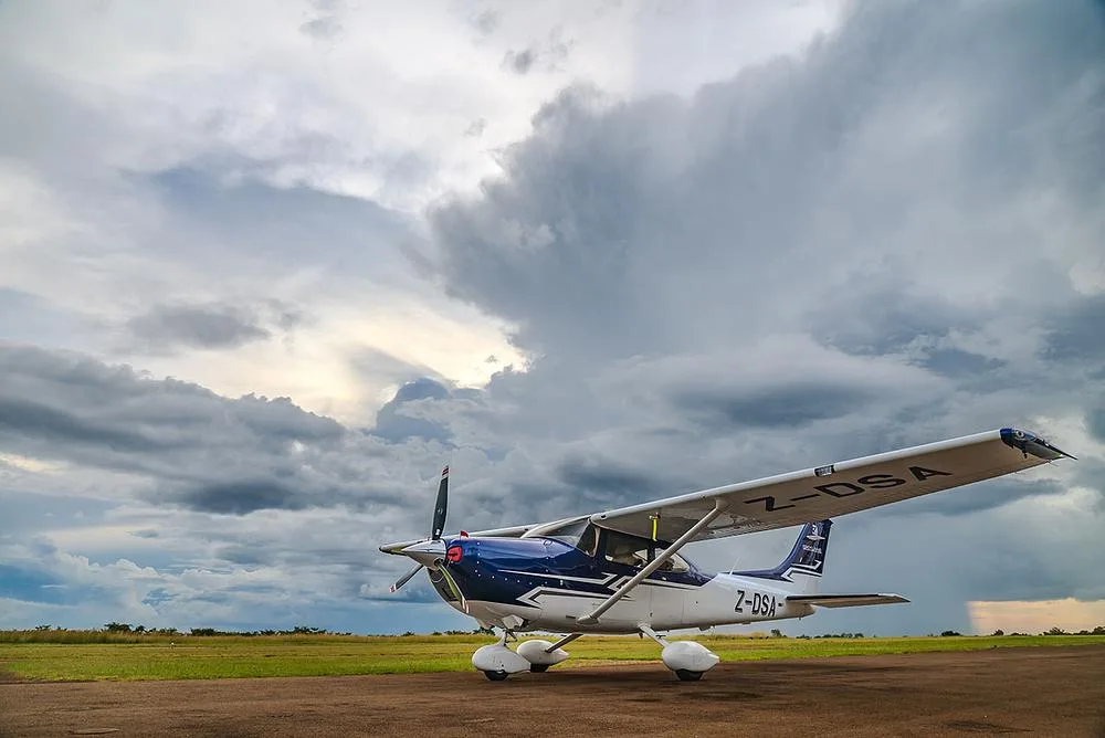
Free — save the 182S Skylane to your watchlist and track it in one place.
More CESSNA 182S SKYLANEmanuals & documents
- C182 Systems - FAA SafetySystems Description
- CESSNA 182S SKYLANE PERFORMANCE DATAPerformance Data
- VISUAL INSPECTION - Cessna Flyer AssociationService Bulletins
- SKYLANE 182T - Tropical Aviation DistributorsAvionics Manual
- Floatplane Source Noise Measurements Summary of Measurements, Data and Analyses for the Cessna 182S Skylane and De Havilland Canada DHC-2 BeaverPerformance
- Exhaust Systems Engine Mounts Carb Air BoxesSystems Description
- AAIB Bulletin No: 4/2003Other Documents
- Airworthiness Approval Note - Civil Aviation AuthorityType Certificate
- Cessna 182S Skylane N965CWChecklist
- Cessna 182S Skylane ChecklistChecklist
If you fly the CESSNA 182S SKYLANE, you may also be researching these.


In this document
Weight Limits
The maximum takeoff weight for the Cessna T182 T is 3,100 lbs (1,406 kg). This section details the various weight categories including maximum landing weight and zero fuel weight, ensuring pilots are aware of the limits for safe operation.
Center of Gravity (CG) Limits
The document specifies the acceptable center of gravity range for the Cessna T182 T, which is between 34.0 inches and 40.0 inches from the datum. This section explains how to measure and calculate the CG based on the aircraft's loading configuration.
Weight and Balance Calculation Procedures
Pilots are provided with step-by-step procedures for calculating the weight and balance before flight. This includes how to use the weight and balance chart, and the importance of ensuring the aircraft is within limits for safe operation.
Loading Instructions
This section outlines the recommended loading practices for passengers, baggage, and fuel to maintain the aircraft's balance. It emphasizes distributing weight evenly and securing all items to prevent shifting during flight.
Safety notes
- Improper weight distribution can lead to loss of control during flight.
- Always verify weight and balance before each flight.
Full document text
SECTION 6 CESSNA WEIGHT AND BALANCE/EQUIPMENT LIST MODEL 182T NAV III WEIGHT AND BALANCE The following information will enable you to operate your Cessna within the prescribed weight and center-of-gravity limitations. To determine weight and balance, use the Sample Loading Problem (Figure 6-3), Loading Graph (Figure 6-4), and Center-of-Gravity Moment Envelope (Figure 6-7) as follows: Enter the appropriate basic empty weight and moment/1000 from the weight and balance records for your airplane in the YOUR AIRPLANE column of the Sample Loading Problem. NOTE In addition to the basic empty weight and moment noted on these records, the C.G. arm (FS) is also shown, but need not be used on the Sample Loading Problem. The moment which is shown must be divided by 1000 and this value used as the moment/1000 on the loading problem. Use the Loading Graph to determine the moment/1000 for each additional item to be carried; then list these on the loading problem. NOTE Loading Graph information for the pilot, passengers and baggage is based on seats positioned for average occupants and baggage loaded in the center of the baggage areas as shown on the Loading Arrangements diagram. For loadings which may differ from these, the Sample Loading Problem lists fuselage stations (FS) for these items to indicate their forward and aft C.G. range limitations (seat travel and baggage area limitation). Refer to Figures 6-5 and 6-6 for additional loading information. Additional moment calculations, based on the actual weight and C.G. arm (FS) of the item being loaded, must be made if the position of the load is different from that shown on the Loading Graph. (Continued Next Page) 16- 6-8 U.S. 182TPHAUS-02 CESSNA SECTION 6 MODEL 182T NAV III WEIGHT AND BALANCE/EQUIPMENT LIST WEIGHT AND BALANCE (Continued) Total the weights and moments/1000 and plot these values on the Center of Gravity Moment Envelope to determine whether the point falls within the envelope, and if the loading is acceptable. BAGGAGE TIEDOWN A nylon baggage net having four tiedown straps is provided as standard equipment to secure baggage in the area aft of the rear seat (baggage areas, A, B and C). Eight eyebolts serve as attaching points for the net. A placard on the baggage door defines the weight limitations in the baggage areas. When baggage area A is utilized for baggage only, the four forward eyebolts should be used. When only baggage area B is used, the eyebolts just aft of the baggage door and the eyebolts above or below the shelf area may be used. When only baggage area C is utilized, the eyebolts above and below the shelf area should be used. When the cabin floor (baggage areas A and B) is utilized for baggage, the four forward eyebolts and the eyebolts mounted above or below the shelf area should be used. When there is baggage in areas B and C, the eyebolts just aft of the baggage door and the eyebolts above and below the shelf area should be used. (Continued Next Page) |1821 182TPHAUS-02 U.S. 6-9 SECTION 6 CESSNA WEIGHT AND BALANCE/EQUIPMENT LIST MODEL 182T NAV III WEIGHT AND BALANCE (Continued) When baggage is contained in all three areas, the two forward eyebolts on the cabin floor, the eyebolts just aft of the baggage door or the eyebolts at the bottom of the forward portion of the shelf area and the eyebolts near the upper forward surface of the shelf area should be used. The rear bench seat can be removed to access the floorboard area of the rear cabin. Baggage may then be tied down using ten tiedown eyebolts to standard attach points located in the interior area of the airplane shown in Figure 6-6. The maximum allowable floor loading of the rear cabin area is 200 pounds/square foot; however, when items with small or sharp support areas are carried, the installation of a plywood floor is recommended to protect the airplane structure. The maximum rated load weight capacity for each of the ten tiedowns is 140 pounds. Rope, strap or cable used for tiedown should be rated at a minimum of ten times the load weight capacity of the tiedown fittings used. Weight and balance calculations for items in the area of the rear seat and baggage area can be figured on the Loading Graph using the lines labeled Rear Passengers or Cargo. 16-10 U.S. 182TPHAUS-02 CESSNA SECTION 6 MODEL 182T NAV III WEIGHT AND BALANCE/EQUIPMENT LIST SAMPLE LOADING PROBLEM WEIGHT AND MOMENT TABULATION SAMPLE ITEM DESCRIPTION AIRPLANE YOUR AIRPLANE Moment Moment Weight Weight (Lb-ins. (Lb-ins. (Lbs.) (Lbs.) /1000) /1000) ! 1. Basic Empty Weight (Use the data pertaining to your airplane as it is equipped. Includes fuel and full oil) presently unusable 1924 70.9 2. Usable Fuel (At 6 Lbs./Gal.) Standard Fuel 87 Gallons Maximum Reduced Fuel (64 Gallons) 3. Pilot and Front Passenger (FS 32 to 50) 522 24.3 340 12.6 4. Rear Passengers (FS 74) 200 14.8 - Cargo Replacing Rear Passenger Seat (FS 65 to 82) 5. *Baggage "A" (FS 82 to 109) 120 Pounds Maximum 100 9.7 *Baggage "B" (FS 109 to 124) 80 Pounds Maximum 24 3.0 *Baggage "C" (FS 124 to 134) 80 Pounds Maximum 6. RAMP WEIGHT AND MOMENT 3110 135.3 7. Fuel allowance for engine start, taxi and runup -10 -0.5 8. TAKEOFF WEIGHT AND MOMENT 3100 134.8 9. * (Subtract Step 7 from Step 6) Locate this point (3100 at 134.8) on the Center-of-Gravity Moment Envelope, and since this point falls within the envelope, the loading is acceptable, providing that flight time is allowed for fuel burn-off to a maximum of 2950 pounds before landing. The maximum allowable combined weight capacity for baggage in areas A, B and C is 200 pounds. The maximum allowable combined weight capacity in areas B and C is 80 pounds. Figure 6-3 (Sheet 1 of 2) 182TPHAUS-02 U.S. 6-11 CESSNA MODEL 182T NAV III SECTION 6 WEIGHT AND BALANCE/EQUIPMENT LIST AIRPLANE WEIGHING FORM 150 Reference datum (firewall, front face. Waterline (WL) - Inches lower portion)} $100. FS.0.0 25.98- 50- -50- -100 -100 -50 MAC 58.80 Level on leveling screws 50 100 150 200 250 300 350
Show full textShow less
Fuselage Station (FS) Inches NOTE It is the responsibility of the pilot to make sure that the airplane is loaded properly. MEASURING A AND B MEASURE A AND 8 PER PILOT'S] OPERATING HANDBOOK INSTRUCTIONS TO ASSIST IN LOCATING CG WITH AIRPLANE WEIGHED ON LANDING GEAR Leveling Provisions Longitudinal Left side of tallcon at FS 130.65 and 171.65 N2217L 18281674 POSITION LEFT SIDE [RIGHT SIDE NOSE SCALE READING SCALE DRIFT Symbol NET WEIGHT (LBS) 771,62 0 L 771,62 Lbs 778,23 0 R 778,23 Lbs 559,97 0 Nw 559,97 Lbs AIRPLANE TOTAL AS WEIGHED W 2.109,82 Lbs FORMULA for Longitudinal CG: (NOSE GEAR NET WEIGHT) ( )*(B) (X) = (A) - ==== NOSE AND MAIN LANDING GEAR WEIGHT TOTALED ( ) INCHES ( ) AFT OF DATUM 559,97 * 66,08 41,36 26,3 X = ( 58,9 ) inch MAC= =% 2.109,82 BASIC EMPTY WEIGHT AND CENTER-OF-GRAVITY TABLE ITEM WEIGHT POUNDS CG ARM (INCHES) MOMENT (INCH- POUNDS / 1000) AIRPLANE (CALCULATED OR AS WEIGHED INCLUDES ALL UNDRAINABLE FLUIDS, FULL OIL AND FULL TKS-FLUID) 2.109,82 41,36 87,27 DRAINABLE UNUSABLE FUEL AT( 6.0 POUNDS PER GALLON) - (5 gallons) BASIC EMPTY WEIGHT (TKS FULL) BASIC EMPTY WEIGHT (TKS EMPTY) Date of weighing: 30,00 48,00 1,44 2.139,82 41,45 88,71 2.093,82 39,53 AA 82,77 20.04.2020 Sign CRS: GUPY3 DE.145.0% DE.66.8671 plus B/C Maintenance Gm FIGURE 6-1. Airplane Weighing Form airplus Maintenance GmbH DE.145.0307 FAA 6UPY361C 6-5 SECTION 6 CESSNA WEIGHT AND BALANCE/EQUIPMENT LIST MODEL 182T NAV III SAMPLE LOADING PROBLEM YOUR AIRPLANE YOUR AIRPLANE YOUR AIRPLANE Moment Moment Moment Weight (lbs.) Weight (Lb-ins, /1000) (lbs.) (Lb-ins, /1000) Weight (lbs.) (Lb-ins, /1000) When several loading configurations are representative of your operations, it may be useful to fill out one or more of the above columns so that specific loadings are available at a glance. 16-12 U.S. Figure 6-3 (Sheet 2) 182TPHAUS-02 | CESSNA MODEL 182T NAV III SECTION 6 WEIGHT AND BALANCE/EQUIPMENT LIST B4066: LOADING GRAPH Load Moment/1000 (Kilograms - Millimeters) 0 50 100 150 200 250 300 350 400 250 550 87 Gal. Max (329,3 Liters) 80 225 500 450 400 350 300- 250 Pilot and Front Passenger Fuel (6 lb.) (302.8) 70 (265.0) 64 (242.2) 60. /(227.1) 50 189.3 40 (151.4) 200 175 Rear Passengers or Cargo 150 125 100 200 30 (113.6) 150 100 75 Baggage "A" 50 Load Weight (Pounds) 50 0 25 Baggage "B" Baggage "C") Loading Graph 0 05 10 15 20 25 30 35 Load Moment/1000 (Pounds - Inches) NOTE Line representing adjustable seats shows the pilot and front seat passenger center-of-gravity on adjustable seats positioned for an average occupant. Refer to the Loading Arrangements diagram for forward and aft limits of occupant C.G. range. Figure 6-4 182TPHAUS-02 U.S. 6-13 Load Weight (Kilograms) SECTION 6 CESSNA WEIGHT AND BALANCE/EQUIPMENT LIST MODEL 182T NAV III LOADING ARRANGEMENTS B4067 C.G. Arm C.G. Arm (FS) *37 (32-50) (FS) *37 Pilot Pass (32-50) [Pilot Pass **74 74 Rear pass. (65-82) Cargo **97 **97 A (82-109) A **116 **116 B (109–124) B 124 **129 C **129 124 C 134 134 Standard seating Rear passenger seat removed FS ·C➤◄B➤◄ACargo FS FS FS 0.00 134.00 FS 109.00 FS 65.00 124.00 82.00 0766T1021 * Pilot or passenger center-of-gravity on adjustable seats positioned for average occupant. Numbers in parentheses indicate forward and aft limits of occupant center-of-gravity range. ** Arms measured to the center of the areas shown. NOTE • The usable fuel C.G. arm is located at FS 46.50. ⚫ The aft baggage wall (approximate FS 134.00) can be used as a convenient interior reference point for determining the location of baggage area fuselage stations. ☑Figure 6-5 16-14 U.S. 182TPHAUS-02 CESSNA MODEL 182T NAV III B406B Rear wall SECTION 6 WEIGHT AND BALANCE/EQUIPMENT LIST INTERNAL CABIN DIMENSIONS Baggage shelf of cabin 13.00 33.00 42.00 48.50 48.00 Firewall 58.75 48.25 68.75 65.25 65.30 Cabin Width Measurements Tiedown rings Rear doorpost Forward doorpost (10 standard) bulkhead bulkhead Face of instrument panel *31.00 **34.50 *36.00 **42.00 *34.00 **41.50 Firewall : 130120 100 90 80 70 60 50 40 30 20 10 0 FS 134 124 110 CODE FS 65.30 Door Opening Dimensions *Cabin floor Width Width Height Height (top) (bottom) (front) (rear) **Lower window line Cabin doors 32.00 36.50 41.00 38.50 Baggage door 15.75 15.75 22.00 20.50 NOTE • Maximum allowable floor loading: 200 pounds/square foot. All dimensions shown are in inches. Figure 6-6 |182TP 182TPHAUS-02 0785T1020 U.S. 6-15 - SECTION 6 CESSNA WEIGHT AND BALANCE/EQUIPMENT LIST MODEL 182T NAV III CENTER-OF-GRAVITY MOMENT ENVELOPE 84069 Loaded Airplane Moment/1000 (Kilogram-Millimeters) 650 750 950 850 1050 1150 1350 1550 1250 1450 Loaded Airplane Weight (Pounds) 3200 1650 - 1450 Maximum Takeoff Weight 3100 Pounds 3100 3000 Maximum Landing Weight 1400 -1350 2950 2950 Pounds 2900 -1300 2800 1250 2700 2600 2500 - 1200 1150 1100 2400 2300 2200 1050 - 1000 Center-of-Gravity 2100 950 Moment Envelope 2000 900 1900 850 1800 55 65 75 85 95 105 115 125 135 145 Loaded Airplane Moment/1000 Pounds-Inches) NOTE If takeoff weight is more than maximum landing weight, allow flight time for fuel burn off to 2950 pounds before landing. 6-16 U.S. Figure 6-7 182TPHAUS-02 Loaded Airplane Weight (Kilograms) : Loaded Airplane Weight (Pounds) CESSNA SECTION 6 MODEL 182T NAV III WEIGHT AND BALANCE/EQUIPMENT LIST 84070 CENTER-OF-GRAVITY LIMITS Airplanes C.G. Location - Millimeters Aft of Datum (FS 0.0) 900 1000 1100 1200 850 950 1050 1150 1250 3200 -1450 Maximum Takeoff Weight 3100 Pounds 3100 -1400 Maximum Landing 3000 Weight 2950 Pounds --1350 2950 2900 -1300 2800 2700 -1250 -1200 2600 -1150 2500 Center-of-Gravity Limits: -1100 2400 .1050 2300 2200 -1000 2100 2000 1900 950 -900 850 1800 32 34 36 38 40 42 44 46 48 50 Airplanes C.G. Location - Inches Aft of Datum (FS 0.0) NOTE If takeoff weight is more than maximum landing weight, allow flight time for fuel burn off to 2950 pounds before landing. 1182TPH 182TPHAUS-02 Figure 6-8 U.S. 6-17/6-18 Loaded Airplane Weight (Kilograms)
3,799 CESSNA 182S SKYLANE parts for sale
See all →
Parts listed for sale by vetted eBay sellers — confirmed on eBay at checkout.