HEATER INSTALLATION INSTRUCTIONS FOR CD11214K5
Cessna 195 · Wiring Diagram
Overview
This document provides detailed installation instructions for the C&D Associates, Inc. combustion heater model CD11214K5, specifically designed for Cessna Model 190, 195, 195A, and 195B aircraft. It outlines the necessary steps for removing the existing heater, installing the new heater, and ensuring proper electrical and plumbing connections. The instructions emphasize compliance with FAA regulations and the importance of following the aircraft's original Type Certificate (TC). Additionally, it includes testing procedures to verify the heater's operational integrity after installation, ensuring safety and functionality for the aircraft's heating system.
- The heater installation is for Cessna Model 190, 195, 195A, and 195B.
- Ensure compliance with FAA regulations and the aircraft's original Type Certificate.
- The new heater weighs 25 lbs, replacing an old heater of 18 lbs.
- Electrical requirements for the heater are 12VDC at 20 Amps.
- Fuel consumption during maximum operation is 1.25 gallons per hour.
Document
Source
Originally published by janitrol.aero. Sprinkle hosts a reference copy with an added summary, specifications and searchable full text.
Document details
- Type
- Wiring Diagram
- Year
- 2015
- Pages
- 24
- File size
- 1.2 MB
- Publisher
- janitrol.aero
Common. Rarer than 1% of the aircraft models we track.
Most owners only have the POH. Here's the essential set for the Cessna 195.
- Pilot's Operating Handbook / AFM
- Checklist
- Maintenance Manual
- Parts Catalog (IPC)
- Systems & Wiring
- Service Bulletins
- Type Certificate (TCDS)
Cessna 195 for sale now
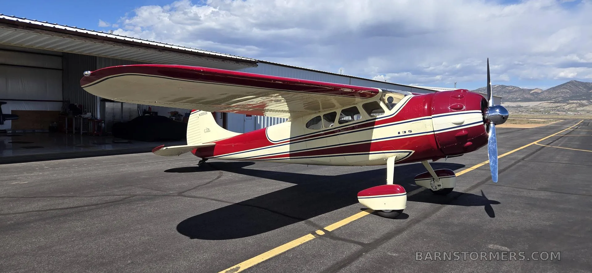
Free — save the 195 to your watchlist and track it in one place.
More Cessna 195manuals & documents
See all 16 →- Radiotelephony Manual CAP 413Training Manual
- Installation Instructions – Corrugated Control SkinParts Catalog
- Type Acceptance Report TAR 14/21B/5 – Cessna 190/195Other Documents
- Airworthiness Directive Schedule Aeroplanes Cessna 195 SeriesAirworthiness Directives
- FAA Notification regarding Electronic Ignition Systems and Oil Scavenging Pumps for Cessna Model 195Service Bulletins
- SAFO 10016Other Documents
- SAFO 09002Airworthiness Directives
- AOPA PILOTPilot's Operating Handbook
- Performance Data for Cessna 195Performance Data
- Cessna 195 Parts CatalogParts Catalog
- Wiring Diagram for Cessna 195Wiring Diagram
- Cessna 195 With Jacobs Engine R-755Systems Description
If you fly the Cessna 195, you may also be researching these.


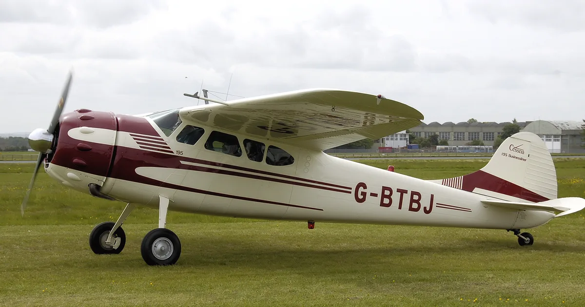
In this document
Preparation
The preparation section outlines the removal of the existing combustion heater and related components. It emphasizes following the Aircraft Service Manual or other FAA-approved sources for proper removal procedures. It also instructs on the installation of the new TSO-C20 approved combustion heater.
Installation
This section details the installation process for the new heater, including modifications to the cabin floor for proper fitment. It includes specific measurements for cutting and drilling, as well as securing the heater and its components in place.
Electrical Connections
The electrical connections section provides guidance on identifying and connecting the old wires to the new heater. It specifies which wires to use for power and ground connections, ensuring that the heater operates correctly with the existing electrical system.
Testing
The testing section outlines the operational tests that must be completed after installation. It includes instructions for installing a temperature probe, verifying temperature settings, and ensuring that the heater operates within specified parameters.
Documentation and Parts Requirement
This section lists the necessary documentation and parts required for the installation, including FAA/PMA supplements, installation instructions, and specific part numbers for the heater and its components.
Safety notes
- Verify that the thermal couple is not touching the plenum internal wall during testing.
- Ensure all wires are secure and free of obstruction and chaffing before operation.
Full document text
INSTALLATION INSTRUCTIONS IN14010K3 2/19/04 Page 1 of 4 Rev. H dated 5/7/15 302 POST ROAD, BUCHANAN, MI 49107 USA PH: 269-695-7469 FX: 269-695-6004 WEB: www.cdaircraftheaters.com EMAIL: sales@aircraftheater.com HEATER INSTALLATION INSTRUCTIONS FOR CD14010K3 For Cessna Aircraft 310, 310A, S/N 35000 thru 35546 READ COMPLETE INSTRUCTIONS BEFORE BEGINNING INSTALLATION This system has been built to be installed on an aircraft that conforms to that aircrafts original Type Certificate (TC). If aircraft has been modified from the original TC (modifications such as props, engines, fuel system etc.) contact C&D Associates, Inc. for possible adjustments to this installation. Accomplish all wiring in accordance with AC43.13-1B Chapter 11, Electrical Systems. Accomplish all plumbing in accordance with AC43.13-1B Chapter 8, Section 2, par. 8-31. LOG OF REVISIONS Rev. Description Pages Revised Date H Reformatted and updated ‘test after installation’ section all 5/7/15 1. PREPARATION 1.1. Heater Removal: Follow the Aircraft Service Manual or other FAA approved source for removal of the existing South Wind combustion heater. 2. INSTALLATION 2.1. Install the C&D Associates, Inc. TSO-C20 Approved Combustion Heater utilizing the existing Aircraft Service Manual or other FAA approved source where applicable. 2.2. When removing electrical connections from the old heater, identify the airframe wires and their location on the old heater terminal strip or electrical cannon plug. Some of these wires will be used in the new installation. On the new heater terminal strip, connect "C" pin or E119N wire (wire that becomes hot when heater switch is turned on) to terminal 1. Connect ground, "A" pin or E-225 wire to terminal 5 (ground). Connect red wire coming from combustion air blower to terminal #1. Tape off wire numbers "B" or 423-N, "D" or E-120N and "E" or F-121N. Optional heater hour meter may be connected to terminal #2. Optional overheat light may be connected to terminal #4 on the heater strip. Refer to typical wiring schematic figure 7 page 37 of Maintenance Manual for Aircraft Combustion Heaters (MM10001). 2.3. Remove the old safety valve assembly from the firewall. Install the new fuel shut-off in place of the safety valve. Reuse the T-fitting from the safety valve and install it in the shut-off. Reconnect the fuel lines to the Tee as originally installed and secure to shelf with tie wrap or clamps. Install #3 fuel line from the new shut-off to the heater. Wire the remote solenoid shut-off to terminal #2 on heater. INSTALLATION INSTRUCTIONS IN14010K3 2/19/04 Page 2 of 5 Rev. H dated 5/7/15 302 POST ROAD, BUCHANAN, MI 49107 USA PH: 269-695-7469 FX: 269-695-6004 WEB: www.cdaircraftheaters.com EMAIL: sales@aircraftheater.com 2.4. Install the combustion air blower above the heater on the existing shelf and connect to the combustion air inlet, using the red sceet hose. Connect the short black wire to airframe ground and positive red wire to heater terminal strip at terminal #1. 2.5. Install the combustion air inlet scarf forward (opposite of exhaust for scooping in air). Installation should be 12" in front of and in line with exhaust by making a 1-1/2" hole. Use the new inlet as a pattern, drilling four 3/16" holes. Place the combustion air inlet inside and secure with four 8/32" screws. Connect the black ceet hose to aluminum combustion air inlet and the stainless steel angle adapter on the combustion air blower housing. Short wire goes to ground, long wire to terminal # 1 on terminal strip. 2.6. The adjustable duct switch sensor P/N CD21253 is to be installed aft of the heater in the plenum. Make two 1/16" holes 2-5/8" apart in a convenient location. Half way between the 1/16" holes, drill a 1/2" hole for the thermister and mount the switch using two sheet metal screws. Red wire to terminal #2, blue wire to terminal #3 and yellow (or orange) wires to thermostat control non-polarity yellow wires. FIGURE 1 3. TESTING 3.1. HEATER OPERATIONAL TEST AFTER INSTALLATION: IMPORTANT!! Please complete the followings steps after the new heater is installed in the aircraft. (Heater terminal strip numbered 1 2 3 4 5 6) 3.1.1 Install a temperature probe (min 0-500° F) in the outlet plenum 6-8” aft of the heater. A good location would be approx. 6” aft of the heater or near the thermostat sensor. Usually you can find a small access point somewhere in the ducting aft of the heater. CAUTION: Verify thermal couple is not touching plenum internal wall. 3.1.2 Setting upper limit temperature upper limit switch 3.1.2.1 If your heater is equipped with a CD21252….. Place a 6” 20G jumper wire with 2 small alligator clips (or the like) across the heater terminal strip numbers 2 and 3, which will bypass the aircraft thermostat. (Fig. 2) CAUTION: Be sure not to short any other terminals. INSTALLATION INSTRUCTIONS IN14010K3 2/19/04 Page 3 of 5 Rev. H dated 5/7/15 302 POST ROAD, BUCHANAN, MI 49107 USA PH: 269-695-7469 FX: 269-695-6004 WEB: www.cdaircraftheaters.com EMAIL: sales@aircraftheater.com With the heater running, verify that the outlet plenum temp. is approx. 250°. Adjust the temperature of the heat duct outlet distribution plenum to an average ambient temperature as follows. • For non-pressurized aircraft set switch to a low of 215º and a high of 255º. NOTE: Adjustment is made by rotating a small 1/16” screw located next to the wires on the side of the switch. It may have a dab of inspectors lacquer over the screw. Rotation clockwise one turn will increase temperature approx. 20° F. Decrease temperature by turning counterclockwise (Fig 3). After sensor is adjusted, place small drop of tamper proof seal on adjustment screw to lock in settings so as to not change due to vibration. Use a product that can be easily removed for readjustment if necessary. Remove the jumper wire and verify that the temperature is controlled by the aircraft thermostat
Show full textShow less
from low (approx. 75° F) to medium to high (approx. 250° F) which is what the cycling switch is set at. Remove the temperature probe sealing the hole with high temperature silicone. 3.1.2.2 If your heater is not equipped with CD21252….. Upper limit adjustments should be made in accordance with aircraft manufacturer’s instructions. 3.1.3 Install the fuel pressure gauge (0-15). Tee into as shown. (Fig. 4) With the heater running, verify fuel pressure. • Preferred pressure is 8psi. (6.5psi min, 10psi max) Figure 4 FUEL SUPPLY FROM HEATER FUEL PUMP OR REGULATOR HEATER CONNECTION FUEL PRESSURE GAUGE 0-15 PSI FOR AV GAS CYCLING SW. ADJUSTMENT CYCLING SWITCH P/N 21252 TERMINAL STRIP JUMPER WIRE BYPASSING THERMOSTAT SENSOR (AIRCRAFT WIRES NOT INSTALLED) OVERHEAT SWITCH NUMBER PLATE Figure 2 Figure 3 INSTALLATION INSTRUCTIONS IN14010K3 2/19/04 Page 4 of 5 Rev. H dated 5/7/15 302 POST ROAD, BUCHANAN, MI 49107 USA PH: 269-695-7469 FX: 269-695-6004 WEB: www.cdaircraftheaters.com EMAIL: sales@aircraftheater.com 3.1.4 Remove the fuel gauge installed in step 3.1.3. Leave the “tee” fitting and cap off for future pressure readings if desired. 3.2 Verify proper installation is completed in accordance with the aircraft maintenance manual. 3.2.1 Verify all wires are secure and free of obstruction and chaffing. 3.2.2 If the hoses need to be replaced, we recommend Sceet-6 (1 ½”) red from the blower to the heater and Ceet-6 (1 ½”) black from outside air to the blower. 3.2.3 For additional information see the “maintenance manual (MM10001)” included with this heater under “Testing after installation or overhaul.” 4. After installation, complete the operation and heat output tests specified in the C&D Associates, Inc. MM10001 Maintenance Manual for aircraft combustion heaters Rev L, dated 5/21/15 or later FAA approved revision. Tests should be accomplished in accordance with section 10.3 operational test, and 10.4 for heat output. Also in accordance with the “Instructions for Continued Airworthiness” “Preflight/Operational check and Shutdown Procedure.” Rev E dated 5-21-15. These FAA-approved Instructions for Continued Airworthiness must be complied with and become a permanent part of the Aircraft Operations and Procedures manual. 5. Documentation: 5.1. Weight & Balance. 5.1.1. If changed remove old heater of 18 lbs (verify weight). And install new heater kit of 25 lbs. The aircraft requires a weight and balance and a 337 must be completed and a copy of the STC attached. The logbook entry should contain the STC #SA00971CH and PMA Supplement #38. Original heater replacement is authorized by way of FAA form 337. Alteration of aircraft by way of STC or PMA supplemental number and date must be recorded in the appropriate aircraft records. 5.1.2. If unchanged removal of the Combustion Heater and the installation of the C&D Associates Products TSO-C20 approved heater will have no net effect on weight and balance or electrical load requirements. 5.2. Insert the following statement (label 21503 provided) in the aircraft flight manual: “C&D Associates Inc. Combustion heater has been installed in this aircraft. Please follow the aircraft-operating manual for combustion heater operating sequence and/or C&D Associates Inc. Instructions for airworthiness” located in MM10001 Rev I dated 8/1/14 or later FAA approved revision.” 5.3. Utilize existing aircraft combustion heater operating instructions or other FAA approved combustion heater operating instructions where applicable. 5.5 Electrical requirements: 24VDC at 15 Amp. 5.6 Fuel consumption: Maximum operation 1.5 gal/hour INSTALLATION INSTRUCTIONS IN14010K3 2/19/04 Page 5 of 5 Rev. H dated 5/7/15 302 POST ROAD, BUCHANAN, MI 49107 USA PH: 269-695-7469 FX: 269-695-6004 WEB: www.cdaircraftheaters.com EMAIL: sales@aircraftheater.com DOCUMENTATION AND PARTS REQUIREMENT TABLE DOCUMENTATION Quantity 1. FAA/PMA Supplement #38 ____ 2. Installation Instructions IN14010K3 ____ 3. Label for flight manual ____ 4. MM10001 Maintenance Manual ____ 5. Quality Assurance Certificate of Compliance #527 ____ 6. STC #SA00971CH ____ 7. 337 Form PARTS S/N 1. (1) Heater CD14010-1 ____ ________ 2. (1) Blower Assy 21415 ____ 3. (1) Solid State Duct Sw. 21253 ____ ________ (1) Rotary Rheostat 21255 ____ 4. (1) Fuel Line (24”) #3 21081 ____ 5. (1) Fuel Line (40”) #3 21081 ____ 6. (4) Nut 60139 ____ (4) Sleeve 60211 ____ 7. Hose, Sceet (2’) 60199 ____ 8. Hose, Ceet (3’) 60198 ____ 9. (4) Worm Drive Clamps 60900-28 ____ 10. (1) Drain Line #4 (7”) 22336 ____ 11. (1) Drain Hose 21279 ____ 12. (1) Regulator 20801 ____ ________ a. Reuse Customer Original #2 TEE FITTING b. (1) Elbow MS20822-3 13. (1) Retainer, Exhaust 20632 ____ 14. (1) Mount, Bracket 21191B ____ 15. (1) Clamps 60900-104 ____ Initials:________________ Date:_______________ IN12006K4 2/19/04 Rev F dated 8/11/15 Page 1 of 4 302 POST ROAD, BUCHANAN, MI 49107 USA PH: 269-695-7469 FX: 269-695-6004 WEB: www.CDaircraftheaters.com EMAIL: sales@aircraftheater.com HEATER INSTALLATION INSTRUCTIONS FOR MODEL CD12006K4 For Piper Aircraft PA-30, S/N 30-2 thru 30-401 READ COMPLETE INSTRUCTIONS BEFORE BEGINNING INSTALLATION This system has been built to be installed on an aircraft that conforms to that aircrafts original Type Certificate (TC). If aircraft has been modified from the original TC (modifications such as props, engines, fuel system etc.) contact C&D Associates, Inc. for possible adjustments to this installation. Accomplish all wiring in accordance with AC43.13-1B Chapter 11, Electrical Systems. Accomplish all plumbing in accordance with AC43.13-1B Chapter 8, Section 2, par. 8-31. LOG OF REVISIONS Rev. Description Pages Revised Date F 1. PREPARATION 1.1. Heater Removal: Follow the Aircraft Service Manual or other FAA approved source for removal of the existing South Wind combustion heater. 2. INSTALLATION 2.1. Install the C&D Associates, Inc., TSO-C20 Approved combustion heater utilizing the existing Aircraft Service Manual or other FAA approved source where applicable, with the following exceptions: 2.2. Remove the old safety valve assembly from the firewall. Install the new fuel shut-off in place of the safety valve. Reuse the original fuel inlet fitting from the old safety valve and install it in the new shut-off. Reconnect the fuel lines to the new shutoff as originally installed and secure with tie wrap or clamps. Install new #4 fuel line from the shut-off to the heater. Wire the remote solenoid shut-off to terminal #2 on heater. 2.3. The exhaust of the new heater must not be modified, however the exhaust shroud (shroud covering the exhaust pipe) may be trimmed to within .25 inch of the aircraft exterior skin once the heater is mounted in the aircraft. 2.4. ELECTRICAL CONNECTIONS 2.4.1. Check wires removed from original heater for the following: 2.4.1.1. Master switch ON, heater OFF. One of the wires from the old heater will be HOT. This wire will not be used (tape off). 2.4.1.2 Master ON, heater ON. Of the remaining wires one will now become HOT. This wire should be connected to terminal #1 on the new heater. 2.4.1.3 With switches off, use OHM meter to identify ground wire and connect to terminal #5 on the new heater terminal strip. Tape off any remaining old wires as they will not be used. The new combustion air blower red wire should be connected to terminal #1 and black wire to ground or terminal #5. 2.4.1.4 If aircraft has an old mechanical thermostat and you are reusing it, connect to terminal #2 and terminal #3 of new heater. If it is to be replaced remove it along with its push-pull cable. See installation instructions of the new electronic adjustable duct thermostat switch CD21253 included with the kit. 2.4.1.5 Optional hour meter is connected to terminal #2. Optional overheat light may be connected to terminal #4 on the heater strip. IN12006K4 2/19/04 Rev F dated 8/11/15 Page 2 of 4 302 POST ROAD, BUCHANAN, MI 49107 USA PH: 269-695-7469 FX: 269-695-6004 WEB: www.CDaircraftheaters.com EMAIL: sales@aircraftheater.com FIGURE 1 3. TESTING 3.1 HEATER OPERATIONAL TEST AFTER INSTALLATION: IMPORTANT!! Please complete the followings steps after the new heater is installed in the aircraft. (Heater terminal strip numbered 1 2 3 4 5 6) 3.1.1 Install a temperature probe (min 0-500° F) in the outlet plenum 6-8” aft of the heater. A good location would be approx. 6” aft of the heater or near the thermostat sensor. Usually you can find a small access point somewhere in the ducting aft of the heater. CAUTION: Verify thermal couple is not touching plenum internal wall. 3.1.2 Setting upper limit temperature upper limit switch 3.1.2.1 If your heater is equipped with a CD21252….. Place a 6” 20G jumper wire with 2 small alligator clips (or the like) across the heater terminal strip numbers 2 and 3, which will bypass the aircraft thermostat. (Fig. 2) CAUTION: Be sure not to short any other terminals. With the heater running, verify that the outlet plenum temp. is approx. 250°. Adjust the temperature of the heat duct outlet distribution plenum to an average ambient temperature as follows. • For non-pressurized aircraft set switch to a low of 215º and a high of 255º. NOTE: Adjustment is made by rotating a small 1/16” screw located next to the wires on the side of the switch. It may have a dab of inspectors lacquer over the screw. Rotation clockwise one turn will increase temperature approx. 20° F. Decrease temperature by turning counterclockwise (Fig 3). After sensor is adjusted, place small drop of tamper proof seal on adjustment screw to lock in settings so as to not change due to vibration. Use a product that can be easily removed for readjustment if necessary. Remove the jumper wire and verify that the temperature is controlled by the aircraft thermostat from low (approx. 75° F) to medium to high (approx. 250° F) which is what the cycling switch is set at. Remove the temperature probe sealing the hole with high temperature silicone. IN12006K4 2/19/04 Rev F dated 8/11/15 Page 3 of 4 302 POST ROAD, BUCHANAN, MI 49107 USA PH: 269-695-7469 FX: 269-695-6004 WEB: www.CDaircraftheaters.com EMAIL: sales@aircraftheater.com 3.1.2.2 If your heater is not equipped with CD21252….. Upper limit adjustments should be made in accordance with aircraft manufacturer’s instructions. 3.1.3 Install the fuel pressure gauge (0-15). Tee into as shown. (Fig. 4) With the heater running, verify fuel pressure. • Preferred pressure is 8psi. (6.5psi min, 10psi max) Figure 4 3.1.4 Remove the fuel gauge installed in step 3.1.3. Leave the “tee” fitting and cap off for future pressure readings if desired. 3.2 Verify proper installation is completed in accordance with the aircraft maintenance manual. 3.2.1 Verify all wires are secure and free of obstruction and chaffing. 3.2.2 If the hoses need to be replaced, we recommend Sceet-6 (1 ½”) red from the blower to the heater and Ceet-6 (1 ½”) black from outside air to the blower. 3.2.3 For additional information see the “maintenance manual (MM10001)” included with this heater under “Testing after installation or overhaul.” 4. After installation, complete the operation and heat output tests specified in the C&D Associates, Inc. MM10001 Maintenance Manual for aircraft combustion heaters Rev L, dated 5/21/15 or later FAA approved revision. Tests should be accomplished in accordance with section 10.3 operational test, and 10.4 for heat output. Also in accordance with the “Instructions for Continued Airworthiness” “Preflight/Operational check and Shutdown Procedure.” Rev E dated 5-21-15. These FAA-approved Instructions for Continued Airworthiness must be complied with and become a permanent part of the Aircraft Operations and Procedures manual. FUEL SUPPLY FROM HEATER FUEL PUMP OR REGULATOR HEATER CONNECTION FUEL PRESSURE GAUGE 0-15 PSI FOR AV GAS CYCLING SW. ADJUSTMENT CYCLING SWITCH P/N 21252 TERMINAL STRIP JUMPER WIRE BYPASSING THERMOSTAT SENSOR (AIRCRAFT WIRES NOT INSTALLED) OVERHEAT SWITCH NUMBER PLATE Figure 2 Figure 3 IN12006K4 2/19/04 Rev F dated 8/11/15 Page 4 of 4 302 POST ROAD, BUCHANAN, MI 49107 USA PH: 269-695-7469 FX: 269-695-6004 WEB: www.CDaircraftheaters.com EMAIL: sales@aircraftheater.com 5. DOCUMENTATION: 5.1. Weight & Balance. 5.1.1. If changed remove old heater of 18 lbs. (verify weight). And install new heater kit of 25 lbs. The aircraft requires a weight and balance and a 337 must be completed and a copy of the STC attached. The logbook entry should contain the STC #SA00971CH and PMA Supplement #38. Original heater replacement is authorized by way of FAA form 337. Alteration of aircraft by way of STC or PMA supplemental number and date must be recorded in the appropriate aircraft records. 5.1.2. If unchanged removal of the Combustion Heater and the installation of the C&D Associates Products TSO-C20 approved heater will have no net effect on weight and balance or electrical load requirements. 5.2. Insert the following statement (label 21503 provided) in the aircraft flight manual: “C&D Associates Inc. Combustion heater has been installed in this aircraft. Please follow the aircraft-operating manual for combustion heater operating sequence and/or C&D Associates Inc. Instructions for airworthiness” located in MM10001 Rev I dated 8/1/14 or later FAA approved revision.” 5.3. Utilize existing aircraft combustion heater operating instructions or other FAA approved combustion heater operating instructions where applicable. 5.4. NOTE: South Wind AD 81-09-09 Combustion Heater Airworthiness Directive does not apply to the C&D Associates, Inc. Combustion Heater. 5.5. Electrical requirements: 12VDC at 20Amp. 5.6. Fuel consumption: Maximum operation 1.25 gal/hour. DOCUMENTATION AND PARTS REQUIREMENT TABLE DOCUMENTATION Quantity 1. FAA/PMA Supplement #38 ____ 2. Installation Instructions IN12006K4 ____ 3. Label for flight manual ____ 4. MM10001 Maintenance Manual ____ 5. Quality Assurance Certificate of Compliance #527 ____ 6. STC #SA00971CH ____ 7. 337 Form ____ PARTS S/N 1. (1) Heater CD12006-1 ____ ________ 2. (1) Solid State Duct Sw. CD21253 ____ ________ 3. (1) Switch, Rotary CD20654A ____ 4. Hose, Ceet 1 ½” (black) 60198 ____ (4) Worm Drive Clamps (1 ½”) 60900-20 ____ 5. (1) Drain Line #4 21335 ____ 6. (1) Drain Hose 21279 ____ 7. (1) Regulator CD20800 ____ (1) Elbow 60144 ____ (1) Elbow 60380 ____ Initials: ____________ Date:____________ INSTALLATION INSTRUCTIONS IN11214K5 Page 1 of 6 Rev F Dated 8/11/15 302 POST ROAD, BUCHANAN, MI, 49107 USA PH: 269-695-7469 FX: 269-695-6004 WEB: www.cdaircraftheaters.com EMAIL: sales@aircraftheater.com HEATER INSTALLATION INSTRUCTIONS FOR CD11214K5 For Cessna Model 190, 195, 195A, 195B READ COMPLETE INSTRUCTIONS BEFORE BEGINNING INSTALLATION This system has been built to be installed on an aircraft that conforms to that aircrafts original Type Certificate (TC). If aircraft has been modified from the original TC (modifications such as props, engines, fuel system etc.) contact C&D Associates, Inc. for possible adjustments to this installation. Accomplish all wiring in accordance with AC43.13-1B Chapter 11, Electrical Systems. Accomplish all plumbing in accordance with AC43.13-1B Chapter 8, Section 2, par. 8-31. LOG OF REVISIONS Rev. Description Pages Revised Date A 1. PREPARATION 1.1. Heater Removal: 1.1.1. Follow the Aircraft Service Manual or other FAA approved source for removal of the existing combustion heater. 1.1.2. Remove the existing combustion heater, fuel control valve, and remote fuel shutoff valve. The remaining ridged fuel line, extending from the left fuel tank down along the left fuselage, should be plugged with a #4 plug at this point. 1.2. Install the C&D Associates, Inc. TSO-C20 Approved Combustion Heater utilizing the existing Aircraft Service Manual or other FAA approved source where applicable. 2. MODIFICATIONS 2.1. Modify cabin floor as indicated in the drawing on page four. Complete location markings of steps a, b, and e before any cutting. 2.1.1 Locate step A on drawing, cut a 1 5/8” hole in floor at marked location. This hole is to allow the black combustion air hose to pass through. 2.1.2 Locate step B on drawing, drill four ¼” holes in cabin floor at marked locations. Insert four keyed #10- 32 rivnuts for mounting the combustion air blower rubber mounts. 2.1.3 See step C. Install combustion air inlet adapter P/N 21356 in the existing old exhaust hole with scarf down and forward (scoops in air). Fasten with six evenly spaced 3/32” rivets. Connect the black 1 ½” hose to the adapter with a 1 ½” clamp. Route hose through existing lightning hose and up through new 1 5/8” hole (step B). INSTALLATION INSTRUCTIONS IN11214K5 Page 2 of 6 Rev F Dated 8/11/15 302 POST ROAD, BUCHANAN, MI, 49107 USA PH: 269-695-7469 FX: 269-695-6004 WEB: www.cdaircraftheaters.com EMAIL: sales@aircraftheater.com 2.1.4 Locate step D. On the center line of the existing heater mounts, measure over 1 ¾” from the side of the inboard mount (3” back from step C edge) and mark for new exhaust. Measure over 8 ¼” from the side of the inboard heater mount for the new drain. Knockout the inboard mark to 2.625” for the exhaust. The other mark to 5/8” diameter for the new drain. 2.1.5 See step E on the drawing. From the edge of the old heater cavity, remove floor material identified by the dotted line previously marked as indicated on heater modification pattern, page 4. 2.1.6 See step F. Remove from the belly skin the old rectangular combustion air inlet adapter (drill out the old rivets) and install a small 6” by 3” patch using the existing rivet pattern.(see step F) 2.1.7 Set the fuel pump (as shown at step G) on the floor under the area of the ridged fuel line (capped in step 1). Locate the pump as indicated in the drawing with the removable end containing a filter (IN) towards outer skin. Mark the mounting leg holes in the floor per print. Install two ¼” holes for two PN CD21520 rubber mounts. Secure mounts with 60177 washers & 60172 self-locking nuts. Place the pump on the mounts and secure with ground wire, washer, and nuts in place. 3. INSTALLATION 3.1. Remove the two seven inch clamps from the new heater and install through the two mounting brackets that cradle the heater. 3.2. Set the new heater into the cradle. Tighten the two clamps around the heater. Verify that the heater sets completely down onto the two mounts and into the floor cavity. 3.3. Fasten the outlet plenum using four existing screw locations, two outboard and two inboard of the outlet plenum. (see step H) Two holes are in the flange aft of the plenum and may be used as a template to drill two holes for #8 sheet metal screws. (step I) 3.4. Install the combustion air blower by screwing four rubber mounts into the four rivnuts previously installed, (see step A on the drawing). Connect the black hose to the blower inlet and the red hose to the heater/blower outlet with four hose clamps. 3.5. Fuel Pump: Connect fuel line from heater to pump outlet and secure. Install the second fuel line at the pump inlet. Install and tighten AN815-4D #4 union in the other end of hose. Remove the previously installed plug from aircraft ridged fuel line and connect new hose with union in place. 4. ELECTRICAL (See page 6 for wiring schematic) 4.1. Identify the old wires removed from the original heater and at the old switch for the following: (Do this before installing the new switch) 4.1.1. Master switch ON, heater switch OFF. One of the wires from the old heater will be HOT. This wire will not be used (tape off). 4.1.2 Master ON, fan switch ON. 4.1.3 Of the remaining wire, one will now become HOT. This wire should be connected to the new switch blue wire and terminal #6 on the new heater. This is power for the vent fan. 4.1.4 Master on heater switch in heat position. Of the remaining wires one will now become hot and should be connected to terminal #1 of the heater. 4.1.5 Remaining two wires (if they exist) may be used to interconnect the yellow (or orange) wires between the thermostat sensor and the yellow wires (no polarity) on the new switch. 4.1.6 Install the new switch using the old wiring or install new wiring. 4.2. Fuel Pump: Connect ground wire from pump leg to heater terminal strip #5. Hot wire to terminal #2 on heater. 4.3. Combustion Air Blower: Connect black ground wire to black pigtail from heater. White feed wire from pump to white pigtail. INSTALLATION INSTRUCTIONS IN11214K5 Page 3 of 6 Rev F Dated 8/11/15 302 POST ROAD, BUCHANAN, MI, 49107 USA PH: 269-695-7469 FX: 269-695-6004 WEB: www.cdaircraftheaters.com EMAIL: sales@aircraftheater.com 4.4. Outlet plenum with ignition unit and thermostat: Connect ignition wire (white) to terminal strip #2 on heater. Black to main ground line on heater. 4.5. On the outlet plenum connect the thermostat ground black wire to terminal strip #5. Red wire to terminal strip #2. Blue wire to terminal strip #3. Yellow wires from thermostat to yellow wires on switch. 4.6. Optional hour meter is connected to terminal #2. Optional overheat light may be connected to terminal #4 on the heater strip. 5. INTERIOR 5.1. Trim interior to fit. 5.2. Outlet plenum can be customized to distribute heat properly. 6. TESTING 6.1 HEATER OPERATIONAL TEST AFTER INSTALLATION: IMPORTANT!! Please complete the followings steps after the new heater is installed in the aircraft. (Heater terminal strip numbered 1 2 3 4 5 6) 6.1.1 Install a temperature probe (min 0-500° F) in the outlet plenum 6-8” aft of the heater. A good location would be approx. 6” aft of the heater or near the thermostat sensor. Usually you can find a small access point somewhere in the ducting aft of the heater. CAUTION: Verify thermal couple is not touching plenum internal wall. 6.1.2 Setting upper limit temperature upper limit switch 6.1.2.1 If your heater is equipped with a CD21252….. Place a 6” 20G jumper wire with 2 small alligator clips (or the like) across the heater terminal strip numbers 2 and 3, which will bypass the aircraft thermostat. (Fig. 1) CAUTION: Be sure not to short any other terminals. With the heater running, verify that the outlet plenum temp. is approx. 250°. Adjust the temperature of the heat duct outlet distribution plenum to an average ambient temperature as follows. • For non-pressurized aircraft set switch to a low of 215º and a high of 255º. • For pressurized aircraft set switch to a low of 190˚ and a high of 225˚. NOTE: Adjustment is made by rotating a small 1/16” screw located next to the wires on the side of the switch. It may have a dab of inspectors lacquer over the screw. Rotation clockwise one turn will increase temperature approx. 20° F. Decrease temperature by turning counterclockwise (Fig 2). After sensor is adjusted, place small drop of tamper proof seal on adjustment screw to lock in settings so as to not change due to vibration. Use a product that can be easily removed for readjustment if necessary. Remove the jumper wire and verify that the temperature is controlled by the aircraft thermostat from low (approx. 75° F) to medium to high (approx. 250° F) which is what the cycling switch is set at. Remove the temperature probe sealing the hole with high temperature silicone. INSTALLATION INSTRUCTIONS IN11214K5 Page 4 of 6 Rev F Dated 8/11/15 302 POST ROAD, BUCHANAN, MI, 49107 USA PH: 269-695-7469 FX: 269-695-6004 WEB: www.cdaircraftheaters.com EMAIL: sales@aircraftheater.com 6.1.2.2 If your heater is not equipped with CD21252….. Upper limit adjustments should be made in accordance with aircraft manufacturer’s instructions. 6.1.3 Install the fuel pressure gauge (0-15). Tee into as shown. (Fig. 3) With the heater running, verify fuel pressure. • Preferred pressure is 8psi. (6.5psi min, 10psi max) Figure 3 6.1.4 Remove the fuel gauge installed in step 6.1.3. Leave the “tee” fitting and cap off for future pressure readings if desired. 6.2 Verify proper installation is completed in accordance with the aircraft maintenance manual. 6.2.1 Verify all wires are secure and free of obstruction and chaffing. 6.2.2 If the hoses need to be replaced, we recommend Sceet-6 (1 ½”) red from the blower to the heater and Ceet-6 (1 ½”) black from outside air to the blower. 6.2.3 For additional information see the “maintenance manual (MM10001)” included with this heater under “Testing after installation or overhaul.” 7. After installation, complete the operation and heat output tests specified in the C&D Associates, Inc. MM10001 Maintenance Manual for aircraft combustion heaters Rev L, dated 5/21/15 or later FAA approved revision. Tests should be accomplished in accordance with section 10.3 operational test, and 10.4 for heat output. Also in accordance with the “Instructions for Continued Airworthiness” “Preflight/Operational check and Shutdown Procedure.” Rev E dated 5-21-15. These FAA-approved Instructions for Continued Airworthiness must be complied with and become a permanent part of the Aircraft Operations and Procedures manual. FUEL SUPPLY FROM HEATER FUEL PUMP OR REGULATOR HEATER CONNECTION FUEL PRESSURE GAUGE 0-15 PSI FOR AV GAS CYCLING SW. ADJUSTMENT CYCLING SWITCH P/N 21252 TERMINAL STRIP JUMPER WIRE BYPASSING THERMOSTAT SENSOR (AIRCRAFT WIRES NOT INSTALLED) OVERHEAT SWITCH NUMBER PLATE Figure 1 Figure 2 INSTALLATION INSTRUCTIONS IN11214K5 Page 5 of 6 Rev F Dated 8/11/15 302 POST ROAD, BUCHANAN, MI, 49107 USA PH: 269-695-7469 FX: 269-695-6004 WEB: www.cdaircraftheaters.com EMAIL: sales@aircraftheater.com 8. DOCUMENTATION: 8.1. Weight & Balance. 8.1.1. If changed remove old heater of 18 lbs. (verify weight). And install new heater kit of 20 lbs. The aircraft requires a weight and balance and a 337 must be completed and a copy of the STC attached. The logbook entry should contain the STC # SA00971CH and PMA Supplement #38. Original heater replacement is authorized by way of FAA form 337. Alteration of aircraft by way of STC or PMA supplemental number and date must be recorded in the appropriate aircraft records. 8.1.2. If unchanged removal of the Combustion Heater and the installation of the C&D Associates Products TSO-C20 approved heater will have no net effect on weight and balance or electrical load requirements. 8.2. Insert the following statement (label 21503 provided) in the aircraft flight manual: “C&D Associates Inc. Combustion heater has been installed in this aircraft. Please follow the aircraft-operating manual for combustion heater operating sequence and/or C&D Associates Inc. Instructions for airworthiness” located in MM10001 Rev I dated 8/1/14 or later FAA approved revision.” 8.3. Utilize existing aircraft combustion heater operating instructions or other FAA approved combustion heater operating instructions where applicable. 8.4. Electrical requirements: 12VDC at 20Amp. 8.5. Fuel consumption: Maximum operation 1 gal/hour. DOCUMENTATION AND PARTS REQUIREMENT TABLE DOCUMENTATION Quantity 1. FAA/PMA Supplement #38 ____ 2. Installation Instructions IN11214K5 ____ 3. Label for flight manual ____ 4. MM10001 Maintenance Manual ____ 5. Quality Assurance Certificate of Compliance #527 ____ 6. STC #SA00971CH ____ 7. 337 Form ____ PARTS S/N 1. (1) Heater CD11214-1 ____ _______ 2. (2) Clamp (6-7”) 60900-104 ____ 3. (1) Drain 20651 ____ 4. (1) Drain Hose 20652 ____ 5. (1) Outlet Plenum Deflector 21364 ____ 6. (1) Outlet Plenum Shield 21368 ____ 7. (1) Outlet Plenum Assembly 29150 ____ 8. (1) Fuel Pump Assembly 29104 ____ 9. (4) 2” Hose Clamps 60900-28 ____ 10. (1) Hose Ceet 1 ½ Black 60198 ____ 11. (2) Hose Sceet 1 ½” Red 60199 ____ 12. (1) Union 60134 ____ 13. (1) Comb. Air Inlet 21356B ____ 14. (1) Blower Assembly 29052 ____ 15. (1) Fuel Line Assembly (18”) 20715 ____ 16. (1) Switch, Rotary 20654 ____ 17. (1) Wire, 14g white 8’ ____ 18. (1) Wire, 14g blue 8’ ____ 19. (2) Wire, 18g yellow 8’ ____ Initials: ____________ Date:____________ INSTALLATION INSTRUCTIONS IN11214K5 Page 6 of 6 Rev F Dated 8/11/15 302 POST ROAD, BUCHANAN, MI, 49107 USA PH: 269-695-7469 FX: 269-695-6004 WEB: www.cdaircraftheaters.com EMAIL: sales@aircraftheater.com INSTALLATION INSTRUCTIONS CD11215K6 2/19/04 Rev I Dated 8/11/15 Page 1 of 7 302 POST ROAD, BUCHANAN, MI 49107 USA PH: 269-695-7469 FX: 269-695-6004 WEB: www.CDaircraftheaters.com EMAIL: sales@aircraftheater.com HEATER INSTALLATION INSTRUCTIONS FOR CD11215K6 For Lake Model LA-4, LA-4A, LA-4P, LA-4-200 READ COMPLETE INSTRUCTIONS BEFORE BEGINNING INSTALLATION This system has been built to be installed on an aircraft that conforms to that aircrafts original Type Certificate (TC). If aircraft has been modified from the original TC (modifications such as props, engines, fuel system etc.) contact C&D Associates, Inc. for possible adjustments to this installation. Accomplish all wiring in accordance with AC43.13-1B Chapter 11, Electrical Systems. Accomplish all plumbing in accordance with AC43.13-1B Chapter 8, Section 2, par. 8-31. LOG OF REVISIONS Rev. Description Pages Revised Date I Reformatted and updated ‘test after installation’ section All 8/11/15 1. PREPARATION 1.1. Heater Removal: • Follow the Aircraft Service Manual or other FAA approved source for removal of the existing combustion heater. • Remove the existing combustion heater, fuel safety valve and drain line. 1.2. Install the C&D Associates, Inc. TSO-C20 Approved Combustion Heater utilizing the existing Aircraft Service Manual or other FAA approved source where applicable. 2. MODIFICATIONS (See page seven illustrations) 2.1. Combustion air blower: Using the existing rear heater mount bracket, the lower front left edge will be used as a reference point. Mark two lines 1.75” and 2.75” forward and parallel with the aft heater mount to airshaft centerline. From the reference point measure inboard marking two lines parallel with the aircraft center line at 2.125” and 3.625” intersecting the first two lines. Drill four ¼” holes at intersections. Install four 10/32 rivnuts and blower-mounting bracket. Secure the combustion air blower (outlet pointing forward) with the two clamps. When properly installed the blower housing will be inline with and just touching the fiberglass heater bonnet when installed. 2.2 Heater Mounts: Remove the two heater mounts and use as a template for the spacers supplied with the kit. Install spacers under each mount to provide ¼” lift and secure into place. CD11215K6 2/19/04 Rev I Dated 8/11/15 Page 2 of 7 302 POST ROAD, BUCHANAN, MI 49107 USA PH: 269-695-7469 FX: 269-695-6004 WEB: www.CDaircraftheaters.com EMAIL: sales@aircraftheater.com "IN" REUSE THIS FITTING FROM OLD SAFETY VALVE OR "OUT" C&D ASSOCIATES, INC. WWW.AIRCRAFTHEATER.COM FOR INSTALLATION & ELIGIBILITY SEE P/N CD2080_ S/N ____ BUCHANAN, MI 49107 USA REGULATOR/SHUTOFF 269-695-7469 FAA/PMA __VDC ___PSI 2.3 Fuel Pump: Carbureted series only. Mount the pump on the rear heater mount, aft left side in the location of the old safety valve which had been removed. 2.4 Remote Shut Off: Fuel Injected series only. Mount the remote shut off on the rear heater mount, aft left side in the location of the old safety valve, which had been removed. Install T-fitting from old safety valve if required. 2.5 Heater Bonnet 2.5.1 Exhaust: On the right side of the heater bonnet measure aft 5/8” from the back edge of the existing rectangular exhaust hole and 1 7/8” up from the bottom of the mounting flange. Using this location as a center mark cut a 2 ¼” round hole for the exhaust. 2.5.2 Exhaust Deflector: Remove three rivets directly under the new exhaust hole and install the deflector P/N . Fasten by using three 8/32 screws, nuts, and washers. 2.5.3 Combustion Air Inlet: On the left side of the heater bonnet measure 15” from the trailing edge and 2” up from the mounting flange. Drill a ½” hole and temporarily place the bonnet in place. Verify that the drilled hole lines up with the motor shaft. Make any adjustments necessary and then enlarge the hole to 2”. 3. INSTALLATION 3.1 Combustion Air Blower: Install blower on previously installed bracket (see step 2-A). Secure with tow 3” clamps. Make sure air flow outlet is facing forward. Blower assembly should be located in such a way as to minimize clearance between blower housing inlet and the bonnet when installed. 3.2 Heater: Install plenum with hose adapter down (inline with drain). Place the new C&D heater onto the heater mounts with the drain straight down and exhaust off to the right side of the aircraft centerline. With the clamps loosely fastened, place the bonnet in place and adjust the heater to match exhaust location. Secure clamps. 3.3 Drain Line: Install from heater drain along right side of aft heater mount. Connect drain hose from fuel box to drain line. 3.4 Thermostat: Install on right aft end of outlet plenum. Drill two 1/8” dia. Holes 2 ¾” apart. Install one ½” hole half way in between. Mount the thermostat with two sheet metal screws. 4. ELECTRICAL (See page 5 for wiring schematic) 4.1 Identify the old wires removed from the original heater and at the old switch for the following: (Do this before installing the new switch) 4.1.1 Master switch ON, heater switch OFF. One of the wires from the old heater will be HOT. This wire will not be used (tape off). 4.1.2 Master ON, fan switch ON. Of the remaining wire, one will now become HOT. This wire should be connected to the new switch blue wire and terminal #6 on the new heater. This is power for the vent fan. CD11215K6 2/19/04 Rev I Dated 8/11/15 Page 3 of 7 302 POST ROAD, BUCHANAN, MI 49107 USA PH: 269-695-7469 FX: 269-695-6004 WEB: www.CDaircraftheaters.com EMAIL: sales@aircraftheater.com 4.1.3 Master ON, heater switch in HEAT position. Of the remaining wires one will now become hot and should be connected to terminal #1 of the heater. 4.1.4 Remaining two wires (if they exist) may be used to interconnect the yellow wires between the thermostat and the yellow wires on the new switch. 4.1.5 Install the new switch using the old wiring or install new wiring. 4.2 Fuel Pump: 4.2.1 Fuel Pump - Carbureted only. Hot wire to terminal #2 on heater. 4.2.2 Solenoid remote shutoff – Fuel Injected only. Hot wire to terminal #2 on heater. 4.3 Combustion Air Blower: Connect black ground wire to terminal #5 of terminal strip on heater. Red to heater terminal strip #1. 4.4 Outlet plenum with ignition unit and thermostat: Connect ignition wire from terminal strip number #3 to ignition unit. 4.5 On the outlet plenum connect the thermostat ground black wire to terminal strip #5. Red wire to terminal strip #2. Blue wire to terminal strip #3. Yellow wires from thermostat to yellow wires on switch. 4.6 Optional hour meter is connected to terminal #2. Optional overheat light may be connected to terminal #4 on the heater strip. FIGURE 1 5. TESTING 5.1 HEATER OPERATIONAL TEST AFTER INSTALLATION: IMPORTANT!! Please complete the followings steps after the new heater is installed in the aircraft. (Heater terminal strip numbered 1 2 3 4 5 6) 5.1.1 Install a temperature probe (min 0-500° F) in the outlet plenum 6-8” aft of the heater. A good location would be approx. 6” aft of the heater or near the thermostat sensor. Usually you can find a small access point somewhere in the ducting aft of the heater. CAUTION: Verify thermal couple is not touching plenum internal wall. CD11215K6 2/19/04 Rev I Dated 8/11/15 Page 4 of 7 302 POST ROAD, BUCHANAN, MI 49107 USA PH: 269-695-7469 FX: 269-695-6004 WEB: www.CDaircraftheaters.com EMAIL: sales@aircraftheater.com 5.1.2 Setting upper limit temperature upper limit switch 5.1.2.1 If your heater is equipped with a CD21252….. Place a 6” 20G jumper wire with 2 small alligator clips (or the like) across the heater terminal strip numbers 2 and 3, which will bypass the aircraft thermostat. (Fig. 2) CAUTION: Be sure not to short any other terminals. With the heater running, verify that the outlet plenum temp. is approx. 250°. Adjust the temperature of the heat duct outlet distribution plenum to an average ambient temperature as follows. • For non-pressurized aircraft set switch to a low of 215º and a high of 255º. NOTE: Adjustment is made by rotating a small 1/16” screw located next to the wires on the side of the switch. It may have a dab of inspectors lacquer over the screw. Rotation clockwise one turn will increase temperature approx. 20° F. Decrease temperature by turning counterclockwise (Fig 3). After sensor is adjusted, place small drop of tamper proof seal on adjustment screw to lock in settings so as to not change due to vibration. Use a product that can be easily removed for readjustment if necessary. Remove the jumper wire and verify that the temperature is controlled by the aircraft thermostat from low (approx. 75° F) to medium to high (approx. 250° F) which is what the cycling switch is set at. Remove the temperature probe sealing the hole with high temperature silicone. 5.1.2.2 If your heater is not equipped with CD21252….. Upper limit adjustments should be made in accordance with aircraft manufacturer’s instructions. CYCLING SW. ADJUSTMENT CYCLING SWITCH P/N 21252 TERMINAL STRIP JUMPER WIRE BYPASSING THERMOSTAT SENSOR (AIRCRAFT WIRES NOT INSTALLED) OVERHEAT SWITCH NUMBER PLATE Figure 2 Figure 3 CD11215K6 2/19/04 Rev I Dated 8/11/15 Page 5 of 7 302 POST ROAD, BUCHANAN, MI 49107 USA PH: 269-695-7469 FX: 269-695-6004 WEB: www.CDaircraftheaters.com EMAIL: sales@aircraftheater.com 5.1.3 Install the fuel pressure gauge (0-15). Tee into as shown. (Fig. 4) With the heater running, verify fuel pressure. • Preferred pressure is 8psi. (6.5psi min, 10psi max) Figure 4 5.1.4 Remove the fuel gauge installed in step 5.1.3. Leave the “tee” fitting and cap off for future pressure readings if desired. 5.2 Verify proper installation is completed in accordance with the aircraft maintenance manual. 5.2.1 Verify all wires are secure and free of obstruction and chaffing. 5.2.2 If the hoses need to be replaced, we recommend Sceet-6 (1 ½”) red from the blower to the heater and Ceet-6 (1 ½”) black from outside air to the blower. 5.2.3 For additional information see the “maintenance manual (MM10001)” included with this heater under “Testing after installation or overhaul.” 6. After installation, complete the operation and heat output tests specified in the C&D Associates, Inc. MM10001 Maintenance Manual for aircraft combustion heaters Rev L, dated 5/21/15 or later FAA approved revision. Tests should be accomplished in accordance with section 10.3 operational test, and 10.4 for heat output. Also in accordance with the “Instructions for Continued Airworthiness” “Preflight/Operational check and Shutdown Procedure.” Rev E dated 5-21-15. These FAA-approved Instructions for Continued Airworthiness must be complied with and become a permanent part of the Aircraft Operations and Procedures manual. 7. DOCUMENTATION: 7.1 Weight & Balance. 7.1.1 If changed remove old heater of 18 lbs. (verify weight). And install new heater kit of 20 lbs. The aircraft requires a weight and balance and a 337 must be completed and a copy of the STC attached. The logbook entry should contain the STC # SA00971CH and PMA Supplement #38. Original heater replacement is authorized by way of FAA form 337. Alteration of aircraft by way of STC and PMA supplemental number and date must be recorded in the appropriate aircraft records. 7.2 Insert the following statement (label 21503 provided) in the aircraft flight manual: “C&D Associates Inc. Combustion heater has been installed in this aircraft. Please follow the aircraft-operating manual for combustion heater operating sequence and/or C&D Associates Inc. Instructions for airworthiness” located in MM10001 Rev I dated 8/1/14 or later FAA approved revision.” 7.3 Utilize existing aircraft combustion heater operating instructions or other FAA approved combustion heater operating instructions where applicable. 7.4 Electrical requirements: 12VDC at 20Amp. 7.5 Fuel consumption: Maximum operation 1 gal/hour. FUEL SUPPLY FROM HEATER FUEL PUMP OR REGULATOR HEATER CONNECTION FUEL PRESSURE GAUGE 0-15 PSI FOR AV GAS CD11215K6 2/19/04 Rev I Dated 8/11/15 Page 6 of 7 302 POST ROAD, BUCHANAN, MI 49107 USA PH: 269-695-7469 FX: 269-695-6004 WEB: www.CDaircraftheaters.com EMAIL: sales@aircraftheater.com DOCUMENTATION AND PARTS REQUIREMENT TABLE DOCUMENTATION Quantity 1. FAA/PMA Supplement #38 ____ 2. Installation Instructions IN11215K6 ____ 3. Label for flight manual ____ 4. MM10001 Maintenance Manual ____ 5. Quality Assurance Certificate of Compliance #527 ____ 6. STC #SA00971CH ____ 7. 337 Form ____ PARTS S/N 1. (1) Heater CD11215-1 ____ ________ 2. (1) Drain Line #4 21372 ____ 3. (1) Drain Hose 9” 21279 ____ 4. (1) Fuel pump Assy 29103 ____ 5. (1) Inlet Reflector 21373 ____ 6. (1) Blower Assembly 21693 ____ 7. (1) Deflector 20656 ____ 8. (2) Spacer (8” x 1: x ¼”) 20657 ____ 9. (18”) 1 ½” x 18” Sceet Hose 60199 ____ 10. (2) Worm Drive Clamps 60900-20 ____ 11. (1) Fuel Line (10”) #4 20715 ____ 12. (1) Switch, Rotary (OPTIONAL) 20654 ____ 13. (1) Adj. Duct Sw. (OPTIONAL) 21253 ____ ________ 14. (2) Worm Drive Clamps (OPTIONAL) 60900-104 ____ 15. (1) Plenum (OPTIONAL) 21476 ____ 16. (1) Mount (OPTIONAL) 21477 ____ 17. (1) Mount (OPTIONAL) 21478 ____ 18. (1) 7.5 Regulator (OPTIONAL) 20800 ____ 19. (1) 90 deg. elbow (OPT W/20800) 60144 ____ 20. (1) Elbow, 1/8” NPT (OPT W/20800) 60024 ____ Initials: ____________ Date:____________ CD11215K6 2/19/04 Rev I Dated 8/11/15 Page 7 of 7 302 POST ROAD, BUCHANAN, MI 49107 USA PH: 269-695-7469 FX: 269-695-6004 WEB: www.CDaircraftheaters.com EMAIL: sales@aircraftheater.com
What's in the Cessna 195 TCDS
A Type Certificate Data Sheet (TCDS) is the FAA's record of what an aircraft type was approved as. It is the source of truth for weights, seating, fuel and the rules the design was certified against. Expand any line to see what it means.
187 Cessna 195 parts for sale
See all →

Parts listed for sale by vetted eBay sellers — confirmed on eBay at checkout.