NATIONAL EMERGENCY SERVICES CURRICULUM AIRCREW & FLIGHTLINE TASKS
CESSNA A185F · Emergency Procedures
Overview
This document serves as a training guide for aircrew and flightline tasks specifically tailored for the Cessna A185F. It is part of the National Emergency Services Curriculum Project and includes a comprehensive list of operational tasks, safety precautions, and communication procedures necessary for effective mission execution. The guide is intended for pilots, mission observers, and ground crew involved in search and rescue operations, emphasizing the importance of teamwork and adherence to safety protocols. Key topics include radio operation, navigation techniques, and emergency response strategies, ensuring that aircrew members are well-prepared for various scenarios they may encounter during missions.
- The Cessna A185F is equipped with a VHF FM radio for mission communications, operating in the 136 MHz to 174 MHz range.
- Aircrew must report critical mission updates, including takeoff and landing times, to mission base.
- Safety precautions on the flight line include proper startup, taxiing, and fueling procedures.
- Understanding latitude and longitude is essential for navigation and reporting locations during missions.
- Emergency procedures include techniques for ELT searches and post-crash actions.
Document
Source
Originally published by www.gocivilairpatrol.com. Sprinkle hosts a reference copy with an added summary, specifications and searchable full text.
Document details
- Type
- Emergency Procedures
- Year
- 2005
- Pages
- 261
- File size
- 4.7 MB
- Publisher
- www.gocivilairpatrol.com
Common. One of the most common aircraft types we track.
Most owners only have the POH. Here's the essential set for the CESSNA A185F.
- Pilot's Operating Handbook / AFM
- Checklist
- Maintenance Manual
- Parts Catalog (IPC)
- Systems & Wiring
- Service Bulletins
- Type Certificate (TCDS)
CESSNA A185F for sale now

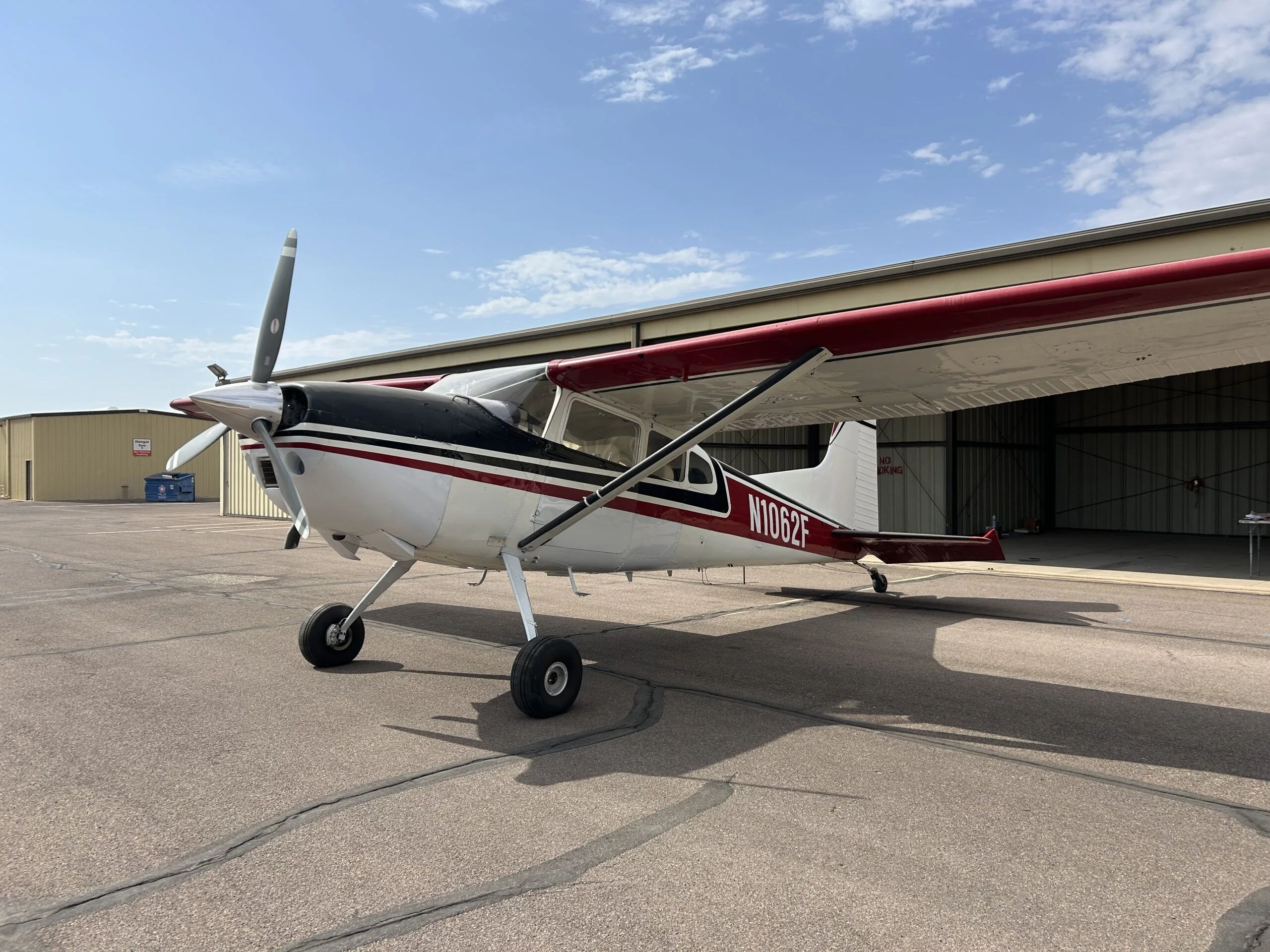

Free — save the A185F to your watchlist and track it in one place.
More CESSNA A185Fmanuals & documents
- ForeFlight Weight and Balance GuideWeight And Balance
- PARTS MANUAL 3000 FLOATS ON CESSNA 180 & 185Checklist
- CANADA FLIGHT SUPPLEMENTTraining Manual
- Airplane Flight Manual Supplement Revision ListFlight Manual
- Model 3000 Ski Installation Procedure: Cessna 185, 185A, 185B, 185C, 185D, 185E, A185E, A185FSpecifications
- SCHEDULE OF AIRWORTHINESS DIRECTIVESAirworthiness Directives
- AIRCRAFT APPRAISAL REPORTChecklist
- wipline floats model 3000 parts manual cessna 180 / 185 - WipaireWiring Diagram
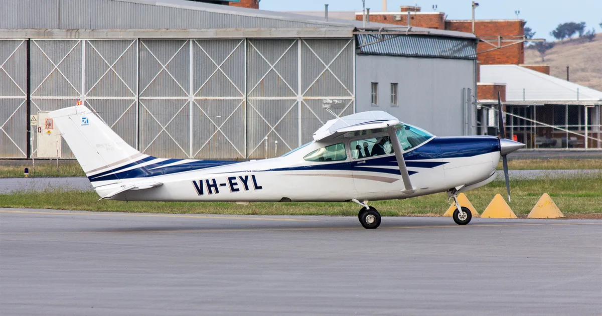
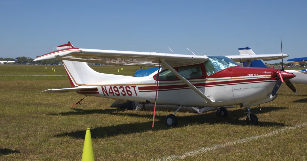
If you fly the CESSNA A185F, you may also be researching these.



In this document
Operations Tasks
This section outlines various operational tasks that aircrew members must perform, including locating points on a map using latitude and longitude, operating aircraft radios, and conducting ELT searches. Each task is designed to enhance the crew's navigation and communication skills, which are critical during missions.
Flight Line Safety Precautions
The document emphasizes the importance of safety on the flight line, detailing responsibilities for flight line marshals, security measures, and hazard identification. It includes guidelines for aircraft startup, taxi procedures, and proper fueling techniques to ensure safe ground operations.
Planning and Mission Execution
This section covers the planning aspects of missions, including pilot duties, safety requirements, and the dangers associated with various weather conditions. It also discusses the importance of crew resource management and effective communication during missions.
Radio Operation
Detailed instructions on operating the aircraft's FM radio and audio panel are provided. This includes setting frequencies, making required reports, and understanding the communication protocols necessary for successful mission coordination.
Emergency Procedures
The guide includes discussions on emergency signals, post-crash actions, and techniques to reduce fatigue during missions. It prepares aircrew members to respond effectively to emergencies and maintain operational readiness.
Safety notes
- Always follow flight line safety precautions to prevent accidents.
- Ensure proper communication protocols are followed to maintain mission safety.
- Be aware of environmental hazards and their impact on flight operations.
Full document text
Aircrew & Flightline Tasks 11 April 2005 Developed as part of the National Emergency Services Curriculum Project NATIONAL EMERGENCY SERVICES CURRICULUM AIRCREW & FLIGHTLINE TASKS The following tasks are included in this task guide. Task # Task Title Command Tasks None Operations Tasks O-0204 LOCATE A POINT ON A MAP USING LATITUDE AND LONGITUDE O-0205 LOCATE A POINT ON A MAP USING THE CAP GRID SYSTEM O-2000 OPERATE THE AIRCRAFT FM RADIO O-2001 OPERATE THE AIRCRAFT AUDIO PANEL O-2002 DEMONSTRATE OPERATION OF THE AIRCRAFT RADIOS O-2003 GRID SECTIONAL CHARTS O-2004 USE A POD TABLE O-2005 OPERATE THE AIRCRAFT DIRECTION FINDER O-2006 PERFORM ELT SEARCHES O-2007 LOCATE AND SILENCE AN ELT ON THE GROUND O-2008 COMPLETE A MISSION SORTIE O-2009 DEMONSTRATE AIR/GROUND TEAM COORDINATION TECHNIQUES O-2010 USE IN-FLIGHT SERVICES O-2011 OPERATE THE VOR AND DME O-2012 OPERATE THE GLOBAL POSITIONING SYSTEM O-2013 PLOT A ROUTE ON A SECTIONAL CHART O-2015 DEMONSTRATE GROUND OPERATIONS AND SAFETY O-2016 DEMONSTRATE SAFETY WHILE TAXIING O-2017 DISCUSS POST-CRASH ACTIONS O-2018 OPERATE THE AIRCRAFT COMMUNICATIONS EQUIPMENT O-2019 USE PROPER NUMBER AND CHARACTER PRONUNCIATION O-2020 USE PROWORDS O-2021 INTERPRET EMERGENCY SIGNALS AND DEMONSTRATE AIR/GROUND TEAM COORDINATION O-2022 DEMONSTRATE SCANING PATTERNS AND LOCATE TARGETS O-2023 DEMONSTRATE TECHNIQUES TO REDUCE FATIGUE O-2024 USE SECTIONAL CHARTS O-2025 TRACK AND RECORD POSITION ON SECTIONALS AND MAPS O-2101 DESCRIBE HOW ELTS ARE DETECTED O-2102 DEMONSTRATE PLANNING AND FLYING A ROUTE SEARCH O-2103 DEMONSTRATE PLANNING AND FLYING A PARALLEL TRACK SEARCH O-2104 DEMONSTRATE PLANNING AND FLYING A CREEPING LINE SEARCH O-2105 DEMONSTRATE PLANNING AND FLYING A POINT BASED SEARCH O-2106 PLAN AND COMMAND A CAP FLIGHT O-2107 PREPARE FOR A TRIP TO A REMOTE MISSION BASE O-2108 ASSIST IN ELT SEARCHES O-2109 ASSIST IN PLANNING AND PERFORMING A ROUTE SEARCH O-2110 ASSIST IN PLANNING AND PERFORMING A PARALLEL TRACK SEARCH O-2112 ASSIST IN PLANNING AND PERFORMING A POINT-BASED SEARCH O-2115 ASSIST IN PLANNING AND PERFORMING A CREEPING LINE SEARCH Task # Task Title O-3001 DISCUSS FLIGHT LINE MARSHALLER’S RESPONSIBILITIES O-3002 STATE THE FIVE FLIGHT LINE SAFETY PRECAUTIONS O-3003 IDENTIFY REQUIREMENTS FOR VEHICLES ON THE FLIGHT LINE O-3004 DISCUSS FLIGHT LINE SECURITY O-3005 DISCUSS FLIGHT LINE HAZARDS O-3006 MARSHALL AN AIRCRAFT O-3007 BE A WING WALKER O-3008 PERFORM AIRCRAFT STARTUP PROCEDURES O-3009 PERFORM AIRCRAFT TAXI PROCEDURES O-3010 PERFORM AIRCRAFT SHUTDOWN AND CHOCKING PROCEDURES O-3011 TIE DOWN AN AIRCRAFT O-3012 DEMONSTRATE PROPER GROUND SAFETY OBSERVER TECHNIQUES O-3013 DEMONSTRATE THE ABILITY TO FUEL AN AIRCRAFT O-3014 DEMONSTRATE KNOWLEDGE OF FLIGHLINE SECURITY O-3101 DISCUSS FLIGHTLINE SUPERVISOR RESPONSIBILITIES O-3102 DISCUSS HOW TO SET UP A FLIGHTLINE O-3103 DISCUSS FLIGHLINE ORGANIZATION O-3104 COORDINATE ACTIVITIES WITH LOCAL FBO O-3105 COORDINATE ACTIVITIES WITH AIRPORT ADMINISTRATION AND SECURITY O-3106 COORDINATE ACTIVITIES WITH LOCAL FIRE DEPARTMENT O-3107 COORDINATE ACTIVITIES WITH LOCAL HOSPITAL AND OR EMT OPERATORS O-3108 SURVEY AIRPORT FOR THE BEST PARKING AREAS AND TAXI ROUTES O-3109 SURVEY AIRPORT FOR HAZARDS AND EMERGENCY EQUIPMENT O-3110 SUPERVISE FLIGHLINE MARSHALLERS O-3111 BRIEF FLIGHTLINE MARSHALLERS AND TRAINEES O-3112 TOW AND PARK AIRCRAFT O-3113 REFUEL AN AIRCRAFT O-3114 KEEP TRACK OF AIRCRAFT REFUELING O-3115 DISCUSS HELICOPTER OPERATIONS Planning Tasks P-0101 KEEP A LOG P-2001 DISCUSS MISSION PILOT DUTIES AND RESPONSIBILITIES P-2002 DISCUSS GENERAL CAP-RELATED SAFETY REQUIREMENTS AND ISSUES P-2003 DISCUSS TYPES OF FLIGHTS PERFORMED BY CAP AIRCREWS P-2004 DISCUSS SECURITY CONCERNS AND PROCEDURES P-2005 DISCUSS MISSION PILOT RESPONSIBILITIES DURING A MISSION P-2007 DISCUSS MISSION OBSERVER DUTIES AND RESPONSIBILITIES P-2008 DISCUSS THE DANGERS OF ICING P-2009 DISCUSS THE DANGERS OF REDUCED VISIBILITY CONDITIONS P-2010 DISCUSS THE DANGERS OF WIND AND THUNDERSTORMS P-2011 DISCUSS THE EFFECTS OF DENSITY ALTITUDE ON AIRCRAFT PERFORMANCE P-2012 IDENTIFY CONTROLLED AND SPECIAL USE AIRSPACES ON A SECTIONAL P-2013 DISCUSS MISSION SCANNER DUTIES AND RESPONSIBILITIES P-2014 DISCUSS CAP LIABIILTY COVERAGE AND MISHAP REPORTING P-2015 ENTER DATA INTO CAP FORMS P-2016 IDENTIFY AND DISCUSS MAJOR AIRCRAFT CONTROLS P-2017 IDENTIFY AND DISCUSS MAJOR AIRCRAFT INSTRUMENTS P-2018 DISCUSS AIRCRAFT WEIGHT AND BALANCE Task # Task Title P-2019 IDENTIFY ITEMS CHECKED DURING AN AIRCRAFT PRE-FLIGHT INSPECTION P-2020 DISCUSS THE DANGER OF WAKE TURBULENCE P-2021 DISCUSS HOW ATMOSHPOERIC AND LIGHTING CONDITIONS EFFECT SCANNING EFFECTIVENESS P-2022 IDENTIFY VISUAL CLUES AND WRECKAGE PATTERNS P-2023 DISCUSS HOW REDUCED VISIBILITY AND TURBULENCE EFFECT SEARCH OPERATIONS P-2024 DISCUSS STRATEGIES TO COMBAT HIGH ALTITUDE EFFECTS P-2025 DISCUSS COMMON SEARCH TERMS P-2026 IDENTIFY WHAT TO LOOK FOR AND RECORD DURING DAMAGE ASSESSMENT MISSIONS P-2027 DESCRIBE CAP SEARCH PATTERNS P-2028 DISCUSS CREW RESOURCE MANAGEMENT P-2119 DEMONSTRATE HOW TO COMPLETE A CAP AIRCRAFT INSPECTION Logistics Tasks L-0001 BASIC COMMUNICATIONS PROCEDURES FOR ES OPERATIONS Finance/Administrative Tasks None O-0204 17-MAR-04 O-0204 LOCATE A POINT ON A MAP USING LATITUDE AND LONGITUDE CONDITIONS Given an aeronautical chart, road map, or topographical map with latitude and longitude lines. You are away from mission base, mounted or dismounted, and must locate your location on map in order to report your location to mission base, an aircraft or another ground element using latitude and longitude. Or, you are coordinating with another search element (ground or air) who has told you his location using the latitude and longitude. You want to plot this point on your map. OBJECTIVES Within 1 minute, the team member announces the correct latitude and longitude of the marked point (using the
Show full textShow less
smallest gradiations of latitude and longitude printed on the map), using correct terminology, and, within 1 minute, can plot a point on the map given the latitude and longitude orally. TRAINING AND EVALUATION Training Outline 1. Latitude and longitude are the objective position measurements used on aeronautical charts. Many road maps and topographical maps also are gridded using this system. a. Lines of longitude run north-south on the map. Lines of latitude run east-west. b. Both latitude and longitude are measured in degrees, minutes and seconds. One minute is 1/60th of a degree, and one second is 1/60th of a minute. In the continental US, latitude numbers are read from south to north (bottom to top), and longitude numbers are read from east to west (right to left) c. Each line of latitude is labeled as either North (if it is above the equator) or South (if it is below the equator). Each line of longitude is labeled as East (if it is east of a longitude line called the Prime Meridian) or West (if it is west of the Prime Meridian) d. To read a lat-long coordinates the symbol “ ° “ means degrees, an apostrophe ( “ ‘ “) means minutes, and a double apostrophe (“ “ “) means seconds. Always read the latitude before the longitude. e. Example: 32° 33’ 44” N, 45° 12’ 52” E means “32 degrees, 33 minutes, and 44 seconds North Latitude, 45 degrees 12 minutes and 52 seconds East Longitude” f. On larger scale maps, or when pinpoint accuracy is not required, seconds are not used. For example, 45° 12’ N, 22° 36 W is read as “45 degrees, 12 minutes North Latitude, 22 degrees 36 minutes West Longitude.” 2. To find the lat-long designation of a known point on the map a. Find the latitude: 1) Find the numbers of the latitude degree lines to the immediate north and south of the point. Write down the lower of the two. (For example, if the point is between 45° and 46° North latitude, write down O-0204 17-MAR-04 “45°“. Also write down if that latitude line is labeled as “North” or “South” (above the equator it will always be “North”). 2) From latitude line chosen above, count up the number of minutes that the point is from the line using the tick marks on the edge of the map (or in the grids if the map is gridded) until you reach the last minute marking before your point. Write down the number of minutes. 3) From the last minute mark, count up the number of seconds to your point (if the map is of a large scale, such as an aviation chart, it will not have marks for seconds. Either stop with the minute measurement, or estimate seconds). Write down the number of seconds. b. Find the longitude. 1) Find the numbers of the longitude degree lines to the immediate east and west of the point. Write down the lower of the two. (For example, if the point is between 22° and 23° West latitude, write down “ 22° “). Also write down if that latitude line is labeled as “East” or “West” (in the western hemisphere it will always be “West”). 2) From longitude line chosen above, count left the number of minutes that the point is from the line using the tick marks on the edge of the map (or in the grids if the map is gridded) until you reach the last minute marking before your point. Write down the number of minutes. 3) From the last minute mark, count left the number of seconds to your point (if the map is of a large scale, such as an aviation chart, it will not have marks for seconds. Either stop with the minute measurement, or estimate seconds). Write down the number of seconds. c. NOTE: If the map is not marked with minutes or seconds, you will have to estimate. Remember, there are 60 minutes in a degree and 60 seconds in a minute. So, if the point is halfway between two degrees, it is at the 30 minute point. If it is one quarter the distance from one degree to another, it is at the 15 minute point. Use the same logic to determine seconds if the map is only gradiated in degrees and minutes. c. Make sure the lat-long coordinate you have written down is in the format Degrees°, Minutes’, Seconds” (North or South) Latitude, Degrees°, Minutes’, Seconds” (East or West) Longitude, 3. To plot a point given the lat-long coordinate: a. Find the correct latitude line and count up the correct number of minutes and seconds (below the equator you would count down, not up). b. Find the correct longitude line and count left the correct number of minutes and seconds (in the eastern hemisphere you would count right, not left). c. Mark the point. Additional Information More detailed information on this topic is available in the Ground Team Member and Leader Reference Text and Mission Aircrew Reference Text. O-0204 17-MAR-04 Evaluation Preparation Setup: Mark a point on a map or chart gridded with latitude and longitude, and give the map to the student. . Tell him whether or not he must report seconds, or just degrees and minutes (depends on the scale of the map). Pick a different grid location from the point and write down the latitude and longitude coordinates. Ensure you have a timer. Because this task is timed, it is necessary to make sure that the student and work area is prepared for testing. The map should be open and complete. If copies of maps are used, they should include all references normally available on the full map to take the exam. Brief Student: Ask the student if he is prepared. Tell the student to tell you the latitude and longitude of the point. Then orally give him the latitude and longitude you wrote down and tell him to show you where that point is on the map. Evaluation Performance Measures Results Determining the grid of a known point. The student: 1. Announces the correct latitude degrees, minutes and seconds within tolerance (see below) P F 2. Announces the correct latitude designation “North” or South” P F 3. Announces the correct longitude degrees, minutes and seconds within tolerance (see below) P F 4. Announces the correct longitude designation “East” or “West” P F 5. Performs the above steps within 1 minute of time P F NOTE: The minimum accuracy for this task is to be within 30 seconds of the correct answer for a map gradiated in minutes. If the map is large enough scale to be gradiated in seconds, then the needed accuracy should be increased. For dismounted work, a ground team with proper maps should be able to plot positions within 10 seconds. The individual determines the location of a designated grid: 6. Plots a point on the map within 1 minute using the correct latitude and longitude degrees, minutes and seconds within tolerance (see accuracy note above). P F Student must receive a pass on all performance measures to qualify in this task. If the individual fails any measure, show what was done wrong and how to do it correctly. O-0205 17-MAR-04 O-0205 LOCATE A POINT ON A MAP USING THE CAP GRID SYSTEM CONDITIONS Given an aeronautical chart, road map, or topographical map gridded with the CAP grid system. You are away from mission base, mounted or dismounted, and must plot your location on a CAP gridded map in order to report it, an aircraft or another ground element. Or, you are coordinating with another search element (ground or air) who has told you his location using the CAP grid system. You want to plot this point on your map. OBJECTIVES Within 1 minute, the team member announces the CAP grid and sub-grid that the point is located in, using correct terminology, and can plot a point on the map given the CAP grid coordinates orally. TRAINING AND EVALUATION Training Outline 1. The CAP grid system is designed for use on aeronautical charts, but can be adapted to any map with latitude/longitude markings around the edge. 2. A grid is a 15 minute latitude by 15 minute longitude box. This is done by dividing the 30 minute by 30 minute boxes already on the aeronautical chart into fourths. Each grid is identified with a number. (For example “I am located in Grid 54”). 3. To locate a position more precisely, mentally divide each grid into four quadrants. The Northwest quadrant is “A”, the Northeast is “B”, the Southwest is “C”, and the Southeast is “D”. Say the quadrant letter after the grid number (for example, “I am in grid 54 B”). 54 55 83 82 A B C D Example of CAP grids (54,55,82 and 83) and lettered quadrants (83A, 83B, 83C, and 83D) 4. To find the grid designation of a known point on the map a. Find the grid number the point is in. O-0205 17-MAR-04 b. Determine which quadrant of the grid the point is in (A, B, C, or D) 5. To plot a point given a grid number and quadrant letter: a. Find the appropriate grid on the map (the grid numbers increase as you look left to right and top to bottom on the map. b. Mark the point in the appropriate lettered quadrant of that grid. Additional Information More detailed information on this topic is available in the Ground Team Member and Leader Reference Text and the Mission Aircrew Reference Text. Evaluation Preparation Setup: Mark a point on a CAP gridded map or chart and give the map to the student. Pick a different grid location from the point and write down the grid and quadrant. Ensure you have a timer. Brief Student: Tell the student to tell you the CAP grid and quadrant designation of the point. Then orally give him the grid and quadrant of the point you wrote down and tell him to show you where that point is on the map. Evaluation Performance Measures Results The individual determines the grid of a known point: 1. Announces the correct grid number and quadrant within 1 minute P F The individual determines the location of a designated grid: 2. Finds the correct numbered grid and quadrant within 1 minute P F Student must receive a pass on all performance measures to qualify in this task. If the individual fails any measure, show what was done wrong and how to do it correctly. O-2000 1-MAR-04 O-2000 OPERATE THE AIRCRAFT FM RADIO CONDITIONS You are a Mission Pilot trainee and must demonstrate how to operate the CAP VHF FM radio. OBJECTIVES Demonstrate and discuss the use of the CAP VHF FM radio, and discuss CAP-specific communications. TRAINING AND EVALUATION Training Outline 1. As a Mission Pilot trainee, knowing how to set up and use the VHF FM radio is essential. This radio enables you to communicate effectively with mission base and ground units. Observers and scanners will normally operate the FM radio. 2. Aviation communications radios. Some aviation frequencies are designed for air-to-air communications and may be used by CAP aircraft (or any other general aviation aircraft). 123.1 MHz is the official SAR frequency. 122.75 and 122.85 MHz are air-to-air communications frequencies (and for use by private airports not open to the general public). 122.90 MHz is the Multicom frequency; it can be used for search and rescue, but is also used for other activities of a temporary, seasonal or emergency nature (note, however, that it is also used by airports without a tower, FSS or UNICOM). Follow your communications plan, if applicable, and don't abuse these frequencies. Look at the sectional to see if 122.90 MHz is used by nearby airports, and always listen before you transmit. 3. Callsigns. CAP aircraft have been authorized to use FAA callsigns, just like the major airlines and commuter air carriers. This helps differentiate us from civil aircraft, air taxis, and many other commercial aircraft. Our FAA authorized callsign is "Cap Flight XX XX," where the numbers are those assigned to each Wing's aircraft. The numbers are stated in 'group' form. For example, the C172 assigned to Amarillo, Texas is numbered 4239, where 42 is the prefix identifying it as a Texas Wing aircraft. The callsign is thus pronounced "Cap Flight Forty-Two Thirty-Nine." It is important to use the group form of pronunciation because FAA air traffic controllers expect it of us. [NOTE: There are a few exceptions to this rule, such as when you perform certain counter drug operations. In these rare cases you may be directed to use the aircraft 'N' number as your callsign.] [NOTE: CAP aircraft should use the word "Rescue" in their callsign when priority handling is critical. From the example above, this would be "Cap Flight Forty-Two Thirty-Nine Rescue." DO NOT abuse the use of this code; it should only be used when you are on a critical mission and you need priority handling. NEVER use the word "rescue" during training or drills.] 4. CAP VHF FM radio. CAP has authorization to use special frequencies in order to communicate with government agencies and our own ground forces. For this purpose CAP aircraft have a VHF FM radio that is separate from the aviation comm radios. This radio is primarily dedicated to air-to-ground communications and is normally operated by the observer or scanner. Several of the frequencies programmed into the radio are frequencies assigned to CAP by the U.S. Air Force, and are used to communicate with CAP bases and ground teams. Others are programmed at the direction of the Wing Communications Officer (e.g., mutual aid, fire, police, park service, forest service, and department of public service); these frequencies almost always require prior permission from the controlling agency before use. [CAP is replacing the older Yaesu and NAT NPX138 radios with the TDFM-136. NPX138 operation is outlined in Attachment 2 of the MART.] O-2000 1-MAR-04 The TDFM-136 is a P25-compliant airborne transceiver capable of operating in the 136 MHz to 174 MHz range (digital or analog) in 2.5 KHz increments. It can have up to 200 operator-accessible memory positions, each capable of storing a receive frequency, a transmit frequency, a separate tone for each receive and transmit frequency, an alphanumeric identifier for each channel, and coded squelch information for each channel. Data can be entered via the 12-button keypad but is normally downloaded from a PC. Operating frequencies, alphanumeric identifiers and other related data are presented on a 96-character, four-line LED matrix display. It is capable of feedback encryption. National will enter the first four main frequencies (Primary, Secondary, Ground Tactical and Air-to-Ground) and the wing communications officers will enter the rest. Guard 1 will be preset to the Air-to-Ground and Guard 2 to the Primary frequency. Therefore, all you will just have to know is how to use the radio. The radio also has a scan function that can scan any or all of the main channels stored in the preset scan lists; scan lists, if enabled, are set by the wing communications officer. As shown in the figure, the radio simultaneously displays two frequencies. The upper line is the Main (MN) frequency and the lower is the Guard (GD) frequency. Normally, you will be set up to transmit and receive on the Main and be able to receive the Guard frequency. This feature allows mission base to contact you at any time (via Guard), no matter what frequency you are using (Main). Controls and normal settings: a. The knob above the MN/GD switch is the power switch and controls volume for Main. The knob above the G1/G2 switch is the volume control for Guard. b. The "Squelch" pushbutton is not used (automatic squelch). Don't push it. c. The MN/GD toggle switch selects the frequency on which you will transmit and receive. It is normally set to MN. d. The G1/G2 toggle switch selects the Guard frequency you are monitoring (G1 = Air-to Ground and G2 = Primary). It is normally set to G1. e. The HI/LO toggle switch selects transmitter power (10 watts or 1 watt). It is normally set to HI. Keypad operation: a. Pressing and holding "4" (Scroll Memory Down) will let you scroll down through the programmed memories (it wraps around). Upon reaching the desired entry, release the button. "6" (Scroll Memory Up) lets you scroll up. [Note: scroll speed increases the longer you hold the buttons.] b. Pressing "5" (Scan) lets you select a scan list to scan, and to start or stop the scan. Once the scan list you want is displayed press # ENTER to start the scan or press * ESC to stop the scan. [Note: this function must be enabled by the wing communications officer for it to work.} c. Pressing and holding "2" (Display - Brighter) will increase display brightness; "8" (Display - Dimmer) decreases brightness. O-2000 1-MAR-04 When you get in the aircraft and power up the radio it should be set to MN, G1 and HI. Use pushbutton 4 or 6 to select the assigned Main frequency (normally Air-to-Ground), and "004 Air/Grd 149.5375" will be displayed on the upper line. The second line should display the Guard 1 frequency (in this case, the same as Main). As another example, lets say you are working with the U.S. Forest Service and have their frequency on Main. Mission base, noting that you have not called in your "Operations Normal" report, calls you using the G1 frequency. You will hear mission base over Guard (its set to G1), regardless of what is coming over the Main frequency. You simply take the MN/GD switch to GD and answer "Ops Normal," and then return the switch to MN and carry on with the mission. 5. Required FM radio reports. As a minimum, the aircrew must report the following to mission base: a. Radio check (initial flight of the day) b. Take off time ("wheels up") c. Time entering a search area d. Time exiting a search area e. Landing time ("wheels down") f. Operations normal ("Ops Normal"), at intervals briefed by mission staff Additional Information This task may be performed in conjunction with Task O-2001 (audio panel). More detailed information on this topic is available in Chapter 4 and Attachment 2 of the MART. Evaluation Preparation Setup: Provide the student access to aircraft radios. Brief Student: You are a Mission Pilot trainee asked to set up and use the CAP VHF FM radio, and discuss other CAP-specific communications. NOTE: The performance measures are designed for the TDFM-136; adjust as necessary for your aircraft. Evaluation Performance measures Results 1. Concerning the aircraft communications radio, discuss: a. Frequencies available for SAR/DR use. P F b. Proper use of CAP callsigns, including when to use "rescue". P F 2. Set up and use the CAP VHF FM radio: a. Power, volume and squelch controls. P F b. Select assigned frequencies (main and guard channels). P F c. Keypad controls (scroll and scan). P F d. Give required mission FM radio reports (may be simulated). P F Student must receive a pass on all performance measures to qualify in this task. If the individual fails any measure, show what was done wrong and how to do it correctly. O-2001 1-MAR-04 O-2001 OPERATE THE AIRCRAFT AUDIO PANEL CONDITIONS You are a Mission Observer trainee and must demonstrate how to operate the aircraft audio panel. OBJECTIVES Demonstrate and discuss the use of the aircraft audio panel. TRAINING AND EVALUATION Training Outline 1. As a Mission Observer trainee, knowing how to set up and use the aircraft audio panel is essential. 2. An audio panel serves as the "hub" for the aircraft's communication and navaid equipment. Whatever type of audio panel is installed in the aircraft, it serves two basic functions: a. Selecting the 'active' radio (COM 1, COM 2, etc.). This is the radio over which you will transmit when you use the push-to-talk switch or the hand mike. b. Allows communication and navigational instruments to be directed to the aircraft's overhead speaker or to the headphones. 3. The position of the switch and the pushbuttons on the audio panel should be checked as part of each preflight. There is no set rules on how they should be set, and settings may vary according to the mission and the airspace you will be flying in. The important thing is to realize how the panel is set up so that your equipment will function as you need and expect them to function. 4. KMA 24. One of the most common older audio panels, the KMA 24 is still found in many CAP aircraft. The switch on the right-hand portion of the panel determines which radio you will transmit on; also, if none of the pushbuttons are depressed, the switch setting (e.g., COM 1) determines which radio you are listening to. The pushbuttons are arranged in two rows: the upper row is associated with the aircraft's overhead speaker, and depressing these pushbuttons will direct their associated equipment to the speaker (e.g., press the ADF pushbutton and the ADF will be heard on the speaker); the bottom row is associated with the headphones and serves the same function. Depressing a pushbutton routes the signal from the associated instrument (e.g., a com radio or the ADF) to the speaker or your headphones, regardless of the setting on the COM switch. This comes in handy when you want to monitor two frequencies at the same time. For example, you have Center on the #1 radio and the COM switch in the COM 1 position. You will be flying near a local airport and want to listen to its CTAF. Set the CTAF in the #2 radio and depress the COM 2 PHONE pushbutton. You will now be able to hear both frequencies, but still will only be able to transmit on Center frequency. The CAP FM radio is usually routed through the TEL pushbuttons, and the DF unit is often routed through the ADF pushbuttons. The two most common mistakes made with this type of audio panel include: transmitting on the wrong frequency because you set the desired frequency in one radio but failed to select the corresponding COM channel; and failing to hear a message over the FM radio because you failed to depress the appropriate pushbutton (usually the TEL pushbutton) to direct the call to the overhead speaker or headphones. O-2001 1-MAR-04 5. PMA7000MS. The PMA7000MS is CAP's newest audio panel, and is installed in conjunction with the new FM radio (TDFM-136). This audio panel was custom-designed to meet CAP SAR operational requirements. In addition to normal audio panel functions, this unit contains an automatic voice-activated (VOX) stereo intercom system with automatic squelch control. Unit power is turned on and off by pushing the Volume knob. In the Off (or Fail-Safe) position the pilot is connected directly to Com 1 to allow communication capability regardless of unit condition (any time power is removed or turned off the audio selector will be placed in the fail-safe mode). The power switch also controls the audio selector panel functions, intercom, and marker beacon receiver. Unless the Mic Selector is in Com 3 mode, at least one of the selected audio LEDs will be on (Com 1 or Com 2). The Volume control knob adjusts the loudness of the intercom for the pilot and observer only; it has no effect on selected radio levels or crewmembers' volume level. Adjust the radios and intercom volume for a comfortable listening level for the pilot. [Most general aviation headsets today have built-in volume controls; therefore, crewmember volume can be adjusted on the headset. For best performance your headset microphone must be placed within ¼ inch of your lips, preferably against them. It is also a good idea to keep the microphone out of a direct wind path.] Mic Selector switch and receiver switches. Receiver audio is selected through two momentary and six latched, push-button, backlit switches. Because the rotary Mic (microphone) Selector switch controls what transceiver is being heard, the Com l and Com 2 push-buttons are of the momentary type and do not remain in when selected. Because of this, you will always hear the audio from the transceiver that is selected for transmit by the rotary Mic Selector switch (in other words, you can't transmit without listening to the receiver). You can identify which receivers are selected by noting which of the switch LEDs are illuminated. Push buttons labeled Nav 1, Nav 2, COM 3, DME, MKR (Marker), ADF and SPR (Speaker) are "latched" type switches. When one of these buttons is pressed, it will stay in the "in" position; press the switch again and it will be in the "out" position and remove that receiver from the audio. When selected, the SPR button will place all selected audio on the aircraft's overhead speaker (Note: the speaker amplifier is not active in the split mode). When the Mic Selector switch is in the Com 1 position, both pilot and observer will be connected to the Com l transceiver. Only the person that presses their Push-to-Talk (PTT) will be heard over the aircraft radio. Turning the rotary switch to the Com 2 position will place pilot and observer on the Com 2 transceiver. The PMA7000MS gives priority to the pilot’s PTT; if the observer it transmitting and the pilot presses her PTT, the pilot’s microphone will be heard over the selected transmitter. Split Mode. Turning the rotary switch to Com 1/2 places the PMA7000MS into "Split Mode." This places the pilot on Com 1 and the observer on the Com 2 transceiver. An example of this useful feature is when the pilot may want to talk to Air Traffic Control while the observer is checking weather with Flight Watch. Switching to Com 1/3, the pilot will be on Com 1 and the observer will be on Com 3 (the FM radio). In Com 2/3, the pilot is on Com 2 and the observer on Com 3. [Note: In split mode the pilot and observer are usually isolated from O-2001 1-MAR-04 each other on the intercom, simultaneously using their respective radios. Depressing the ICS button in split mode will activate VOX intercom between the pilot and observer positions; this permits intercommunication when desired between the crew. Pressing the ICS button again disables this crew intercom function.] The table below summarizes the transmitter combinations (substitute Observer for Copilot): Intercom Mode. A 3-position toggle switch ("Intercom Mode Sel." in the figure) allows the pilot to tailor the intercom function to best meet the current cockpit situation. The following description of the intercom mode function is valid only when the unit is not in the "Split" mode (as mentioned before, the pilot and observer intercom is controlled with the ICS button when in the split mode). ISO (up position): The pilot is isolated from the intercom and is connected only to the aircraft radio system. She will hear the aircraft radio reception (and side tone during radio transmissions). The observer will hear the crewmembers’ intercom and the back seat scanners will hear the observer's intercom; neither will hear aircraft radio receptions or pilot transmissions. ALL (middle position): All crewmembers will hear the aircraft radio and intercom. CREW (down position): The pilot and observer are connected on one intercom channel and have exclusive access to the aircraft radios. Back seat scanners can continue to communicate with themselves without interrupting the pilot or observer. The following table summarizes the intercom modes (substitute Observer for Copilot): Because improper setup of the audio panel can lead to confusion and missed radio calls, do not reposition the switch or any of the pushbuttons without consulting with the Pilot-in-Command! Additional Information More detailed information on this topic is available in Chapter 4 and Attachment 2 of the MART. O-2001 1-MAR-04 Evaluation Preparation Setup: Provide the student access to the aircraft audio panel. Brief Student: You are a Mission Observer trainee asked about setting up and using the aircraft audio panel. NOTE: The performance measures are designed for the PMA7000MS; adjust as necessary for your aircraft. Evaluation Performance measures Results 1. Set up and use the audio panel: a. Power and volume controls. P F b. Microphone selector switch and receiver switches (describe all positions). P F c. Split mode (describe all transmitter combinations). P F d. Intercom modes (describe all modes). P F Student must receive a pass on all performance measures to qualify in this task. If the individual fails any measure, show what was done wrong and how to do it correctly. O-2002 1-MAR-04 O-2002 DEMONSTRATE OPERATION OF THE AIRCRAFT RADIOS CONDITIONS You are a Mission Observer trainee and must demonstrate how to operate the aircraft communications radios and the CAP VHF FM radio. OBJECTIVES Demonstrate and discuss the use of the aircraft communications radios and the CAP VHF FM radio. TRAINING AND EVALUATION Training Outline 1. As a Mission Observer trainee, knowing how to set up and use the aircraft radios is essential. This enables the observer to assist the pilot during times of heavy workloads, and to communicate effectively with mission base and ground units. The aircraft radio is the primary means of communication in aviation. To effectively use the radio, mission pilots and observers must be knowledgeable not only of how to communicate, but when communication is required during CAP missions. Observers may operate the aircraft communications radios in order to reduce pilot workload, and they use the FM radio to communicate with ground units. Some aviation frequencies are designed for air-to-air communications and may be used by CAP aircraft (or any other general aviation aircraft). 123.1 MHz is the official SAR frequency. 122.75 and 122.85 MHz are air-to- air communications frequencies (and for use by private airports not open to the general public). 122.90 MHz is the Multicom frequency; it can be used for search and rescue, but is also used for other activities of a temporary, seasonal or emergency nature (note, however, that it is also used by airports without a tower, FSS or UNICOM). Follow your communications plan, if applicable, and don't abuse these frequencies. Look at the sectional to see if 122.90 MHz is used by nearby airports, and always listen before you transmit. 2. Aviation communications radios. To establish radio communications (a KX 155 is shown), first tune the communications radio to the frequency used by the clearance or ground station. Almost all general-aviation aircraft transmitters and receivers operate in the VHF frequency range 118.0 MHz to 136.975 MHz. Civil Air Patrol aircraft normally have 720-channel radios, and the desired frequency is selected by rotating the frequency select knobs until that frequency appears in the light-emitting diode display, liquid crystal display, or other digital frequency readout or window. The 720-channel radios are normally tuned in increments of 50 kilocycles (e.g., 119.75 or 120.00). They can be tuned in increments of 25 kilocycles (e.g., 119.775) pulling out on the tuning knob, but the last digit of the frequency will not be shown in the display (e.g., 119.775 will be displayed as 119.77). [Sometimes, for brevity, air traffic controllers assign such frequencies as "one-one nine point seven seven," meaning 119.775, not 119.770. The operator cannot physically tune the radio to 119.770, and this may be confusing.] O-2002 1-MAR-04 Before transmitting, first listen to the selected frequency. An untimely transmission can "step on" another transmission from either another airplane or ground facility, so that all the transmissions are garbled. Many pilots have been violated for not complying with instructions that, it was later determined, had been blocked or "stepped on" by another transmission. Next, mentally prepare your message so that the transmission flows naturally without unnecessary pauses and breaks (remember "Who, Where and What"). You may even find it helpful to jot down what you want to say before beginning the transmission. When you first begin using the radio, you may find abbreviated notes to be a convenient means of collecting thoughts with the proper terminology. As your experience level grows, you may find it no longer necessary to prepare using written notes. Stuck mike Occasionally, the transmit button on aircraft radio microphones gets stuck in the transmit position, resulting in a condition commonly referred to as a “stuck mike.” This allows comments and conversation to be unintentionally broadcast. Worse yet, it also has the effect of blocking all other transmissions on that frequency, effectively making the frequency useless for communication by anyone within range of the offending radio. You may suspect a stuck mike when, for no apparent reason, you do not receive replies to your transmissions, especially when more than one frequency has been involved. You may notice that the 'T' (transmit symbol) is constantly displayed on your communications radio and, in the case of the PMA7000MS audio panel, the transmit (TX) light in the lower right-hand corner is on continuously. You may notice a different sound quality to the background silence of the intercom versus the noise heard when the microphone is keyed but no one is talking. Often the problem can be corrected by momentarily re-keying the microphone. If receiver operation is restored, a sticking microphone button is quite likely the problem. 3. Callsigns. CAP aircraft have been authorized to use FAA callsigns, just like the major airlines and commuter air carriers. This helps differentiate us from civil aircraft, air taxis, and many other commercial aircraft. Our FAA authorized callsign is "Cap Flight XX XX," where the numbers are those assigned to each Wing's aircraft. The numbers are stated in 'group' form. For example, the C172 assigned to Amarillo, Texas is numbered 4239, where 42 is the prefix identifying it as a Texas Wing aircraft. The callsign is thus pronounced "Cap Flight Forty-Two Thirty-Nine." It is important to use the group form of pronunciation because FAA air traffic controllers expect it of us. [NOTE: There are a few exceptions to this rule, such as when you perform certain counter drug operations. In these rare cases you may be directed to use the aircraft 'N' number as your callsign.] The initial transmission to a station starts with the name of the station you’re calling (e.g., Amarillo Ground), followed by your aircraft callsign. You almost always identify yourself using your aircraft's CAP flight designation. Once you’ve identified the facility and yourself, state your position (e.g., "at the ramp") and then make your request. [NOTE: CAP aircraft should use the word "Rescue" in their callsign when priority handling is critical. From the example above, this would be "Cap Flight Forty-Two Thirty-Nine Rescue." DO NOT abuse the use of this code; it should only be used when you are on a critical mission and you need priority handling. NEVER use the word "rescue" during training or drills.] 4. CAP VHF FM radio. CAP has authorization to use special frequencies in order to communicate with government agencies and to our own ground forces. For this purpose CAP aircraft have a VHF FM radio that is separate from the aviation comm radios. This radio is dedicated to air-to-ground communications, and is normally operated by the observer or scanner. Several of the frequencies programmed into the radio are frequencies assigned to CAP by the U.S. Air Force, and are used to communicate with CAP bases and ground teams. Others are programmed at the direction of the Wing Communications Officer (e.g., mutual aid, fire, police, park service, forest service, and department of public service); these frequencies almost always require O-2002 1-MAR-04 prior permission from the controlling agency before use. [CAP is replacing the older Yaesu and NAT NPX radios with the TDFM-136 (below), which will be discussed here.] The TDFM-136 is a P25-compliant airborne transceiver capable of operating in the 136 MHz to 174 MHz range (digital or analog) in 2.5 KHz increments. It can have up to 200 operator-accessible memory positions, each capable of storing a receive frequency, a transmit frequency, a separate tone for each receive and transmit frequency, an alphanumeric identifier for each channel, and coded squelch information for each channel. Data can be entered via the 12-button keypad but is normally downloaded from a PC. Operating frequencies, alphanumeric identifiers and other related data are presented on a 96-character, four-line LED matrix display. It is capable of feedback encryption. National will enter the first four main frequencies (Primary, Secondary, Ground Tactical and Air-to-Ground) and the wing communications officers will enter the rest. Guard 1 will be preset to the Air-to-Ground and Guard 2 to the Primary frequency. Therefore, all you will just have to know is how to use the radio. The radio also has a scan function that can scan any or all of the main channels stored in the preset scan lists; scan lists, if enabled, are set by the wing communications officer. As shown in the figure, the radio simultaneously displays two frequencies. The upper line is the Main (MN) frequency and the lower is the Guard (GD) frequency. Normally, you will be set up to transmit and receive on the Main and be able to receive the Guard frequency. This feature allows mission base to contact you at any time (via Guard), no matter what frequency you are using (Main). Controls and normal settings: a. The knob above the MN/GD switch is the power switch and controls volume for Main. The knob above the G1/G2 switch is the volume control for Guard. b. The "Squelch" pushbutton is not used (automatic squelch). Don't push it. c. The MN/GD toggle switch selects the frequency on which you will transmit and receive. It is normally set to MN. d. The G1/G2 toggle switch selects the Guard frequency you are monitoring (G1 = Air-to Ground and G2 = Primary). It is normally set to G1. e. The HI/LO toggle switch selects transmitter power (10 watts or 1 watt). It is normally set to HI. Keypad operation: a. Pressing and holding "4" (Scroll Memory Down) will let you scroll down through the programmed memories (it wraps around). Upon reaching the desired entry, release the button. "6" (Scroll Memory Up) lets you scroll up. [Note: scroll speed increases the longer you hold the buttons.] b. Pressing "5" (Scan) lets you select a scan list to scan, and to start or stop the scan. Once the scan list you want is displayed press # ENTER to start the scan or press * ESC to stop the scan. [Note: this function must be enabled by the wing communications officer for it to work.} O-2002 1-MAR-04 c. Pressing and holding "2" (Display - Brighter) will increase display brightness; "8" (Display - Dimmer) decreases brightness. When you get in the aircraft and power up the radio it should be set to MN, G1 and HI. Use pushbutton 4 or 6 to select the assigned Main frequency (normally Air-to-Ground), and "004 Air/Grd 149.5375" will be displayed on the upper line. The second line should display the Guard 1 frequency (in this case, the same as Main). As another example, lets say you are working with the U.S. Forest Service and have their frequency on Main. Mission base, noting that you have not called in your "Operations Normal" report, calls you using the G1 frequency. You will hear mission base over Guard (its set to G1), regardless of what is coming over the Main frequency. You simply take the MN/GD switch to GD and answer "Ops Normal," and then return the switch to MN and carry on with the mission. 5. Required FM radio reports. As a minimum, the aircrew must report the following to mission base: a. Radio check (initial flight of the day) b. Take off time ("wheels up") c. Time entering a search area d. Time exiting a search area e. Landing time ("wheels down") f. Operations normal ("Ops Normal"), at intervals briefed by mission staff Additional Information More detailed information on this topic is available in Chapter 4 and Attachment 2 of the MART. Evaluation Preparation Setup: Provide the student access to aircraft radios. Brief Student: You are a Mission Observer trainee asked to set up and use the aircraft radios. NOTE: The performance measures are designed for the KX 155 and the TDFM-136; adjust as necessary for your aircraft. Evaluation Performance measures Results 1. Set up and use the aircraft communications radio: a. Power, volume and squelch controls. P F b. 50 and 25 kilocycles frequency adjustments. P F c. Set in primary and standby frequencies, and switch between them (flip-flop). P F d. Discuss proper use of CAP callsigns, including when to use "rescue". P F e. Discuss stuck mike indications and strategies. P F 2. Set up and use the CAP VHF FM radio: a. Power, volume and squelch controls. P F O-2002 1-MAR-04 b. Select assigned frequencies (main and guard channels). P F c. Keypad controls (scroll and scan). P F d. Give required mission FM radio reports (may be simulated). P F Student must receive a pass on all performance measures to qualify in this task. If the individual fails any measure, show what was done wrong and how to do it correctly. O-2003 1-MAR-04 O-2003 GRID SECTIONAL CHARTS CONDITIONS You are a Mission Observer trainee and must grid and use gridded sectional charts. OBJECTIVES Grid a sectional chart using the CAP and the Standardized Lat/Long Grid systems. TRAINING AND EVALUATION Training Outline 1. As a Mission Observer trainee, knowing how to grid a sectional chart and use grids is essential in order to assist the mission pilot in planning a search, and to maintain situational awareness during a search. 2. CAP gird system. The sectional grid system used by Civil Air Patrol divides each sectional’s area into 448 smaller squares. The latitude and longitude boundaries of each sectional chart are shown below. The St. Louis chart, for example, covers an area that is bounded by the following latitudes and longitudes: North 40° 00’ (north boundary), North 36° 00’ (south boundary), West 91°-00’ (west boundary), and West 84°-00’(east boundary). Chart Identifier North Grid Limit South Grid Limit West Grid Limit East Grid Limit Total Grids Seattle Great Falls Billings Twin Cities Green Bay Lake Huron Montreal Halifax SEA GTF BIL MSP GRB LHN MON HFX 49-00N 49-00N 49-00N 49-00N 48-15N 48-00N 48-00N 48-00N 44-30N 44-30N 44-30N 44-30N 44-00N 44-00N 44-00N 44-00N 125-00W 117-00W 109-00W 101-00W 93-00W 85-00W 77-00W 69-00W 117.00W 109-00W 101-00W 93-00W 85-00W 77-00W 69-00W 61-00W 576 576 576 576 544 512 512 512 Klamath Falls Salt Lake City Cheyenne Omaha Chicago Detroit New York LMT SLC CYS OMA ORD DET NYC 44-30N 44-30N 44-30N 44-30N 44-00N 44-00N 44-00N 40-00N 40-00N 40-00N 40-00N 40-00N 40-00N 40-00N 125-00W 117-00W 109-00W 101-00W 93-00W 85-00W 77-00W 117-00W 109-00W 101-00W 93-00W 85-00W 77-00W 69-00W 576 576 576 576 512 512 512 San Francisco Las Vegas Denver Wichita Kansas City St. Louis Cincinnati Washington SFO LAS DEN ICT MKC STL CVG DCA 40-00N 40-00N 40-00N 40-00N 40-00N 40-00N 40-00N 40-00N 36-00N 35-45N 35-45N 36-00N 36-00N 36-00N 36-00N 36-00N 125-00W 118-00W 111-00W 104-00W 97-00W 91-00W 85-00W 79-00W 118-00W 111-00W 104-00W 97-00W 90-00W 84-00W 78-00W 72-00W 448 476 476 448 448 448 448 448 Las Angeles Phoenix Albuquerque Dallas-Ft. Worth Memphis Atlanta Charlotte LAX PHX ABQ DFW MEM ATL CLT 36-00N 35-45N 36-00N 36-00N 36-00N 36-00N 36-00N 32-00N 31-15N 32-00N 32-00N 32-00N 32-00N 32-00N 121-30W 116-00W 109-00W 102-00W 95-00W 88-00W 81-00W 115-00W 109-00W 102-00W 95-00W 88-00W 81-00W 75-00W 416 504 448 448 448 448 384 El Paso San Antonio Houston New Orleans Jacksonville ELP SAT HOU MSY JAX 32-00N 32-00N 32-00N 32-00N 32-00N 28-00N 28-00N 28-00N 28-00N 28-00N 109-00N 103-00W 97-00W 91-00W 85-00W 103-00W 97-00W 91-00W 85-00W 79-00W 384 384 384 384 384 Brownsville Miami BRO MIA 28-00N 28-00N 24-00N 24-00N 103-00W 83-00W 97-00W 77-00W 384 384 O-2003 1-MAR-04 The process begins by dividing the whole area into twenty-eight 1-degree grids, using whole degrees of latitude and longitude. Then each 1-degree grid is divided into four 30-minute grids, using the 30-minute latitude and longitude lines as shown in Figure 8-22. Finally, each of the 30-minute grids is divided into four 15-minute grids, using the 15- and 45-minute latitude and longitude lines. Next, the grid squares are numbered 1 through 448 beginning usually with the most northwest square on the entire sectional, and continuing straight east through number 28. The numbering resumes in the second row, with number 29 placed beneath number 1, 30 beneath 2, and so on through 56. The third row begins with number 57 beneath numbers 1 and 29, and continues through 84. Numbering continues through successive rows until all 448 squares have a number. In cases where two sectionals overlap one another, the Civil Air Patrol always uses the numbering system for the western-most chart of the two in question. You can see this where the overlap area between 90° 00’ and 91° 00’, shown in the first 4 vertical columns, is identified with Kansas City (MKC) grid numbering, not St. Louis. Note too that, since the Kansas City grid numbering is used in this overlap area, the first 4 columns of the St. Louis grid numbering system are omitted. Several other such overlaps exist within the grid system. When circumstances require, a 15-minute grid can be divided into 4 more quadrants using 7 1/2 minute increments of latitude and longitude, creating 4 equal size grids that are approximately 7 1/2 miles square. The quadrants are then identified alphabetically - A through D - starting with the northwest quadrant as A, northeast as B, southwest as C and southeast as D, as shown below. A search area assignment in the southeast quadrant may be given as "Search STL 5D." A B 40-00N 39-45N 39-52.5N 90-00W 89-52.5W 89-45W STL 5 C D Pinpointing an area within the grid system becomes easy once you gain familiarity with the grids' many uses. You soon will be able to quickly plot any area on a map and then fly to it using the basic navigation techniques already discussed. 3. Another means of designating a grid system is the Standardized Latitude and Longitude Grid System. It has an advantage over the sectional standardized grid in that it can be used on any kind of chart that has lines of latitude and longitude already marked. In this system, 1-degree blocks are identified by the intersection of whole numbers of latitude and longitude, such as 36-00N and 102-00W. These points are always designated with the latitude first, such as 36/102, and they identify the area north and west of the intersection of these two lines. In the figure below, the gray shading identifies section 36/102. 37-00N 36-00N 102-00W 103-00W O-2003 1-MAR-04 Next, the 1-degree grid is divided into 4 quadrants using the 30-minute lines of latitude and longitude. Label each quadrant A through D; the northwest quadrant being 36/102A, the northeast 36/102B, the southwest 36/102C, and the southeast 36/102D as shown in the figure below (left). Each quadrant can also be divided into four sub-quadrants, labeled AA, AB, AC, and AD, again starting with the most northwest and proceeding clockwise, as shown the figure below (right). This grid system works on any chart that has latitudes and longitudes printed on it. 102-00W 103-00W 36-00N 37-00N 30' 30' A B C D 36-00N 37-00N 30' 103-00W 102-00W 30' B C D AA AC AD AB 45' 45' Additional Information More detailed information and figures on this topic are available in Chapter 8 of the MART. Attachment 1 of the MART is a reproduction of Attachment E of the U.S. National SAR Supplement to the International Aeronautical and Maritime SAR Manual. Evaluation Preparation Setup: Provide the student with Appendix E of the U.S. National SAR Supplement to the International Aeronautical and Maritime SAR Manual (Attachment 1 of MART), a sectional chart and a plotter. Give the student a sectional (may be out-of-date) and a gridding assignment. Brief Student: You are an Observer trainee asked grid a sectional chart, using both the CAP and the Standardized Latitude and Longitude Grid systems. Evaluation Performance measures Results Given Appendix E of the U.S. National SAR Supplement to the International Aeronautical and Maritime SAR Manual (Attachment 1 of MART), a sectional chart, and a plotter: 1. Grid a sectional using the CAP grid system. P F 2. Given coordinates, draw a grid on the sectional using the Standardized Latitude and Longitude Grid System. P F Student must receive a pass on all performance measures to qualify in this task. If the individual fails any measure, show what was done wrong and how to do it correctly. O-2004 1-MAR-04 O-2004 USE A POD TABLE CONDITIONS You are a Mission Observer trainee and must demonstrate basic knowledge of search planning and the use of the POD table. OBJECTIVES Demonstrate basic knowledge of how search planners determine the Maximum Area of Possibility and Probability Area. Use a POD table to discuss the advantages and disadvantages of various search altitudes and speeds over various types of terrain. TRAINING AND EVALUATION Training Outline 1. As a Mission Observer trainee, basic knowledge of search planning and being able to use the POD table is helpful. 2. The first task in planning a search and rescue mission is to establish the most probable position of the crash site or survivors. If witnesses or other sources provide reliable information concerning an accident, the location may be established without difficulty. If there is little or no information, the planning section chief faces a more difficult task. Regardless of the information available, the planning section chief always prepares a chart to assist in focusing the search and locating the crash site or survivors as quickly as possible. 3. When defining search area limits, the planning section chief first sketches the maximum possibility area. This can focus the initial search in the most likely area and allows use of the charted area to help screen sightings and other reports. Again, the area is roughly circular, centered on the last known position of the missing aircraft. The radius approximates the distance the objective aircraft might have traveled, given the amount of fuel believed aboard at its last known position, and the wind direction and speed. The area is circular because it's always possible the missing pilot may have changed directions following his last known position and flown until his fuel was exhausted. 4. To chart the Maximum Area of Possibility, the planning section chief requires the missing aircraft's last known position, wind direction and velocity, and an estimate of the missing aircraft's fuel endurance and airspeed. If none of this information is available the task is much more difficult, and the search plan is usually based on an assumption that the missing aircraft is located along or near its intended course. 5. Plotting the probability area, the area in the possibility circle where the searchers are most likely to find the aircraft, is the second major factor in search planning. The probability area is determined by the accuracy of the last known position (LKP) in the possibility circle. When this information is not available, the planning section chief must rely on less specific secondary sources of information. Based on experience and the accuracy of available information, the planning section chief defines an area of highest priority to initiate the search. The first search area may be called probability area one: this area begins around the last known position, extends along the intended route, and ends around the intended destination. If a search of probability area one produces negative results, the search may be expanded to cover probability area two, an extension of area one. If this search is unsuccessful, the search area is adjusted once more. O-2004 1-MAR-04 6. Organization is an important element in search planning. The time it takes to locate downed aircraft or survivors could depend on the definition and charting of the search area. As an observer, you should become familiar with each designated search area before the mission is launched. You should use current charts and maps which will enable you to provide additional navigational assistance in accurately positioning the search aircraft over the properly designated area. 7. The size of the search objective, weather, visibility, and ground cover in the search area must be considered when determining the altitude and airspeed for a visual search. Over non-mountainous terrain, a search altitude between 800 and 2000 feet above the terrain is normally used for a visual search. The search visibility and the terrain conditions may affect this selection. As altitude decreases below 500 feet, search effectiveness may actually decrease, due to the "rush effect" of objects on the ground passing through the scanner's field of view more rapidly. Depending upon the number of search aircraft available, planners may also consider the desired probability of detection when selecting an altitude for the search pattern. Although a probability of detection chart is normally used to estimate POD after a search, its use here allows planners to predetermine a mission's chance of success. The POD table shows data for: open, flat terrain; hilly terrain and/or moderate ground cover; and very hilly and/or heavily covered terrain. To the right in the columns beneath "Search Visibility" you see what are, in this case, the desired probabilities of detection. Looking at the open/flat terrain and using 1-mile track spacing, you can see that all three altitudes give at least 50% POD, but a search at 1000 feet above the terrain gives 60%, or 10% more POD, than does a search at 500 feet. Over open terrain, where flight and search visibility are not limiting factors, the table demonstrates that a higher altitude is more likely to yield positive results on a single sortie. Notice that the highest POD, 85%, is obtained when flying at 1,000 feet above the ground using a track spacing of 0.5 nm. If weather or visibility are not limiting factor, why then don't you just always elect to fly that track spacing at 1,000 feet, and always try to obtain that highest of probabilities of detection? You should recall, from the earlier maximum probability area, that you start with a very large area and then try to focus your efforts on smaller probability areas within that larger area. If the incident commander has received a number of leads that have reduced the probable area to a small size, he might task you to fly exactly that track spacing and altitude. If the area is not so small, and you try to fly 1/2- rather than 1-mile track spacing, you will obviously take twice as long to cover the whole area. 8. Execution of search patterns. The incident commander and his staff take into consideration many variables including weather, visibility, aircraft speed, and availability of aircraft and crew resources, experience, and urgency of the situation when developing the search plan. Similarly, the planning section chief considers many variables when selecting the search pattern or patterns to be used. Individual search patterns are covered in O-2004 1-MAR-04 chapters that follow. All questions about how the search is to be conducted must be resolved at the mission briefing. When airborne, crews must focus on executing the briefed plan instead of second-guessing the general staff and improvising. If, for whatever reason, you deviate from the planned search patterns it is imperative that you inform the staff of this during your debriefing. Additional Information More detailed information and figures on this topic are available in Chapter 9 of the MART. Evaluation Preparation Setup: Provide the student with search planning figures (e.g., Chapter 9 of the MART) and a POD table. Brief Student: You are an Observer trainee asked to discuss basic search planning and use a POD table. Evaluation Performance measures Results 1. Discuss how search planners determine the Maximum Area of Possibility and the Probability Area. P F 2. Using a POD table, discuss the advantages and disadvantages of various search altitudes and speeds over the three major types of terrain. P F 3. Discuss the importance of proper execution of search patterns. P F Student must receive a pass on all performance measures to qualify in this task. If the individual fails any measure, show what was done wrong and how to do it correctly. O-2005 17-MAR-04 O-2005 OPERATE THE AIRCRAFT DIRECTION FINDER CONDITIONS You are a Mission Observer trainee and must operate the aircraft Direction Finder. OBJECTIVES Operate the aircraft Direction Finder (DF) in both the Alarm and DF modes, and discuss how the DF should respond during a typical mission. TRAINING AND EVALUATION Training Outline 1. As a Mission Observer trainee, knowing how the aircraft DF works and how to operate it is essential. 2. L-Tronics DF. The L-Tronics LA series Aircraft Direction Finder, the most common DR unit found in CAP aircraft, consists of VHF and UHF receivers, two- or three-element yagi antennas (normally mounted on the bottom of the aircraft) and circuitry. The controls consist of a frequency selector switch, an alarm toggle switch (works like a light switch), and a dual-knob control switch for volume (inner knob) and sensitivity (outer knob). There are two indications: a DF meter and a signal Strength meter. [Note: Some have only the DF meter, but the operation is the same.] The DF unit is normally connected to the aircraft audio system. This connection allows an audible as well as a visual alarm when an ELT signal is detected in ALARM mode. The Alarm mode is the normal mode for routine conditions. It enables the pilot to monitor the emergency frequency (121.5 MHz) without dedicating a communications radio to the task. DO NOT USE THIS MODE DURING A DF SEARCH because the DF function is disabled in the Alarm mode. a. Normal setup. To select the Alarm mode, place the Alarm toggle switch on (up). Set the SENSitivity so that the needle just comes on-scale and the VOLume to a comfortable level (the ear will detect a weak signal far sooner than the alarm). [Note: The Alarm mode is designed to work with weak signals; if an ELT is transmitting nearby and the unit is set to full sensitivity, the receiver may overload.] b. DF setup. If an ELT activates the Alarm, turn the Alarm toggle switch off (down) and verify or select 121.5 on the frequency switch. This activates the DF function and allows you to track the signal. Set the SENSitivity to maximum and the VOLume to a comfortable level. The Alarm mode must not be used during a DF search because the DF function is not operable in the Alarm mode (toggle switch up). c. Searching for an ELT signal. The pilot should climb to an altitude of at least 3000 to 4000 feet AGL, if possible, and fly to the area of the reported ELT signal (but remember, an ELT search begins the minute you take off). If the ELT cannot be heard in the expected area, climb to a higher altitude. If this fails to acquire the signal, start a methodical search (e.g., area or expanding square). Unless the beacon is known to be a 406 MHz O-2005 17-MAR-04 EPIRB or a military beacon (which uses 243 MHz), switch between 121.5 and 243 MHz at least once each minute until a signal is heard. All civil beacons and some military beacons transmit on both frequencies. d. Phases of a typical ELT search: Initial heading. When first heard, the ELT signal will probably be faint and will build slowly in strength over a period of several minutes. Continue flying until a reasonable level of signal is acquired. The DF needle should deflect to one side and the Strength needle should come on-scale. Resist the urge to turn immediately and follow the needle; instead, make a 360° turn at no more than a 30° bank to ensure you get two needle centerings (approximately 180° apart) to verify the heading. When the turn is complete, center the DF needle and fly toward the ELT. Note your heading (write it down) for reference. If the ELT is heard on both 121.5 and 243.0 MHz, compare the headings. If they differ by more than 45° or if the turn produces multiple crossovers, try a new location or climb to a higher altitude to escape from the reflections. While flying toward the ELT the DF needle may wander back and forth around center at 10- to 30-second intervals. This is caused by flying through weak reflections and should be ignored. Fly the heading that keeps needle swings about equal in number, left and right. Signal fade. Don’t become concerned if the signal slowly fades out as you fly towards the ELT. If this happens, continue on your heading for at least six minutes. If you are still headed toward the ELT the signal should slowly build in strength in three or four minutes and be somewhat stronger than before the fade. If the signal does not reappear, return to where the signal was last heard and try a different altitude. Getting close. As you get close to the ELT the signal will get stronger, and you will have to periodically adjust the SENSitivity control to keep the signal strength needle centered (do not decrease the VOLume control as this could overload the receiver). You also need to do this if the DF needle gets too sensitive. Periodically yaw the aircraft and observe the DF needle respond (left and right). Passing over the ELT. A “station passage” is often seen as a rapid fluctuation in signal strength and confused DF readings. Yaw the aircraft to see if the course has reversed (needle goes in the direction of the aircraft turn). If the course has reversed, continue on your heading for a few minutes. Then turn and make several confirmation passages from different angles while continuing your visual search. 3. Becker SAR DF 517. The SAR DF 517 is a precision direction finder was developed for professional SAR (search and rescue) purposes. It has the ability to bear and analyse traditional 121.5 MHz and 243.0 MHz emergency frequencies in the VHF and UHF bands, maritime radio channel 16, and the new digitally encoded 406.025 MHz COSPAS/SARSAT emergency signal. This system incorporates a newly developed and patented antenna (small, rugged and wideband), as well as sophisticated bearing analysis algorithms, allowing delivery of a quick and steady indication for both the 121.5 and 406.025 MHz signals. It also has the ability to track a wide range of training frequencies for training exercises. The direction finder was developed for working under stressful mission conditions such as in an aircraft, helicopter or vehicle. The SAR DF 517 has two modes of operation: a. Emergency Mode. This mode is used for actual SAR missions. In this mode the unit will search for 121.5 MHz, 406.025 MHz, Marine Channel 16 and COSPAS/SARSAT Emergency Signal Transmissions. Depending on selection, the unit will either SCAN all of these frequencies or search on a single selected frequency. To operate the unit in the emergency mode, follow the checklist below: O-2005 17-MAR-04 1) Turn ON 2) Select EMERGENCY 3) Select PAGE 1 4) Verify Correct Antenna Mounting 5) Turn Volume ON 6) Select EMERGENCY Frequency or SCAN mode. 7) SET SQUELCH LEVEL! (Set just above noise level.) b. Training Mode. This mode is used for practice exercises. In this mode the unit will search for specific training frequencies entered by the operator, can also SCAN a group of training frequencies, but EMERGENCY frequencies are ignored when in the training mode. To operate the unit in the training mode, follow the checklist below: (1) (3) (4) (6) (5) (2) (7) (1) (2) (1) 1) Turn ON 2) Select TRAINING O-2005 17-MAR-04 c. Becker SAR DF 517 Highlights: 1) SQUELCH Adjustment. It takes some practice to learn the correct setting of the squelch control. If the squelch is set to high, you may not be able to receive the ELT signal. If the squelch is set to low (in the noise level) you will receive erroneous ELT signals that may tend to “bounce” around the screen. 2) Don’t be afraid to play with the squelch adjustment while in flight. You will quickly learn how to tell the difference between a valid ELT signal and an erroneous signal cause by noise. 3) Be sure to monitor your COMM radio also. Listen for the characteristic ELT “whooping” signal on the correct frequency (usually 121.5 MHz for EMERGENCIES or 121.775 for TRAINING). If you can hear the ELT on your COMM radio, but it is not being indicated on the DF-517, your squelch setting is probably too high. 4) The PILOT should not be watching the DF-517 display. The OBSERVER should be watching the display and giving bearing directions to the pilot. The pilot’s job is to provide the crew a safe flight environment. FLY SAFE! Additional Information (3) (4) (5) (6) (7) (8) (9) (10) (11) 3) Select PAGE 6 4) Select Training Frequency Band 5) Set/Verify Training Frequency. Change only if needed. 6) Press STORE button to save any changes made to training frequency. Not necessary if no changes made. 7) Select PAGE 1 8) Verify Antenna Mounting 9) Turn Volume ON 10) Select Training Frequency or SCAN mode. 11) SET SQUELCH LEVEL! (Set just above noise level.) O-2005 17-MAR-04 DF is covered in Task O-2108, Assist in ELT Searches, and may be performed concurrently with this task. More detailed information and figures on this topic are available in Chapter 10 and Attachment 2 of the MART as well as the User Manual for the Becker SAR-DF 517. Evaluation Preparation Setup: Provide the student with an aircraft and pilot, and a practice beacon. Brief Student: You are a Mission Observer trainee asked to set up the aircraft DF unit and assist in locating a practice beacon. Evaluation Performance measures Results 1. Describe how the aircraft DF works. P F 2. Set up the DF. P F 2. Use the DF during a typical ELT search. Discuss how the DF should respond during the initial phase (include signal fade), when you are getting close, and when you pass over the practice beacon. P F Student must receive a pass on all performance measures to qualify in this task. If the individual fails any measure, show what was done wrong and how to do it correctly. O-2006 17-MAR-04 O-2006 PERFORM ELT SEARCHES CONDITIONS You are a Mission Pilot trainee and must perform ELT searches. OBJECTIVES Locate an Emergency Locator Transmitter (practice beacon) using the homing and wing null ELT search methods. Discuss the aural and metered search methods, and reflection and interference. TRAINING AND EVALUATION Training Outline 1. As a Mission Pilot trainee, knowing how to plan for and locate an Emergency Locator Transmitter (ELT) is essential. There are several methods that can be used, the most common of which are the homing and wing null methods. You should also be familiar the aural and metered search method, and how reflections and signal interference can affect the search. 2. Homing is an electronic search method that uses the Direction Finder (DF) to track the ELT signal to its source. Tune the direction finder (DF) to the ELT operating frequency; the pilot will fly the aircraft to the transmitter. ELT’s may transmit on either 121.5 MHz VHF, 243.0 MHz UHF, or both frequencies simultaneously. These emergency frequencies are usually the ones monitored during a search, but homing procedures can be used on any radio frequency to which both a transmitter and DF receiver can be tuned. a. L-Tronics DF Unit. First you have to determine the direction to the ELT. When you fly directly toward a signal, the left/right DF needle remains centered. However, when you head directly away from the signal, the needle also centers. A simple, quick maneuver is used to determine if you are going toward or away from the signal. Starting with the left/right needle centered, the pilot turns the aircraft in either direction so that the needle moves away from center. If he turns left, and the needle deflects to the right, the ELT is in front. If the pilot turns back to the right to center the needle, and then maintains the needle in the center, you will eventually fly to the ELT. If, in the verification turn, the pilot turns left and the needle swings to the extreme left, then the ELT is behind you. Continue the left turn until the needle returns to the center. You are now heading toward the ELT, and as long as the pilot maintains the needle in the center, you will fly to the ELT. Flying toward the ELT, maintaining the needle in the center of the indicator is the actual homing process. If the needle starts to drift left of center, steer slightly left to bring the needle back to the center. If it starts to drift right, turn slightly back to the right. Once you have completed the direction-verification turn, you will not need large steering corrections to keep the needle in the center. When passing over the ELT or transmission source, the left/right needle will indicate a strong crossover pattern. The needle will make a distinct left-to-right or right-to-left movement and then return to the center. This crossover movement is not a mere fluctuation; the needle swings fully, from one side of the indicator to the other and then returns to the center. During homing you may encounter situations where the needle suddenly drifts to one side then returns to center. If the heading has been steady, and the needle previously centered, such a fluctuation may have been caused by a signal from a second transmitter. Another aircraft nearby can also cause momentary needle fluctuations that you might not hear, but the needle in the DF will react to it. Signal reflections from objects or high terrain can also cause needle fluctuations at low altitudes in mountainous terrain or near metropolitan areas. O-2006 17-MAR-04 b. Becker SAR-DF 517. Just like when using the L-Tronics DF, you will need to determine the bearing to the target. With the Becker DF, you will essentially follow the directions on pages of the display. How do I read the above displays? - Page 1 indicates that the target is 2 degrees to the right, so the observer would tell the pilot to turn 2 degrees right to center the ball at the top of the display. - Page 2 indicates that the target is 2 degrees to the left, so the observer tells the pilot to turn two degrees to the left to center the ball at the top of the display. - Page 3 indicates that the target is 6 degrees to the right, so the observer tells the pilot to turn 6 degrees to right (there is no ball displayed on this page). How do you know when you are over the target? - The “ball” will swing to the 180 degree position on PAGE 1 just after you pass over the target. Page 1: 360°bearing Page 2: expanded ±45° Page 3: bearing text 1) Relative Bearing value. It is very important to realize that this is a relative bearing that is relative to the nose of the aircraft, NOT the heading to be flown. 2) Spread Maximum deviation of un-averaged bearing. Good bearing results even with a spread of 45°as a result of the averaging procedure. Note: as you approach near the ELT and the signal becomes very strong, the spread will narrow. 3) Receive level Field strength. Page 1 shows approximately 50%, Page 2 shows approx. 75% 4) Squelch level Squelch level must be above the noise level without a received signal. 5) Offset Corrects for antenna alignment (adjusted in the edit-menu). 6) Mounting Page 1 shows a BOTTOM mounted antenna. Page 3 shows TOP mounted. 7) LS: ---:--- Internal timer (LS meaning last signal) indicating the time since the last signal was received, displayed in min /sec O-2006 17-MAR-04 - When you are exactly over the target you may notice a “cone of influence” similar to passing over a VOR during which the signal may be lost momentarily before it swings to 180 degrees. 3. Wing null. The wing null (or wing shadow) method is based on the assumption that the metal skin of the search aircraft’s wing and fuselage will block incoming ELT signals from the receiving antenna during steep- banked turns. Due to the length of the description of this search method and the number of figures, refer to the "Wing Shadow method (wing null)" section of the Mission Aircrew Reference Text (MART) for details. 4. The aural (or hearing) search technique is based on an assumption that an ELT's area of apparent equal signal strength is circular. Please refer to the "Aural (or hearing) search" section of the MART for details. 5. To employ the metered search method, the observer uses a signal strength meter to monitor the ELT signal. Once the aircraft enters the search area, the observer plots two positions of equal meter strength. Please refer to the "Metered search" section of the MART for details. 6. Signal reflection and interference. Radio signals reflect off terrain and manmade objects, and this can be a problem for search and rescue teams. In an electronic search, it is vitally important to know if the equipment is reacting to reflected signals and what you can do to overcome the problem. Please refer to the "Signal Reflection and Interference" section of the MART. Additional Information Using the DF is covered in Task O-2005 (Operate the Aircraft DF), and may be performed concurrently with this task. More detailed information and figures on this topic are available in Chapter 10 and Attachment 2 of the MART and the user’s manual for the Becker SAR-DF 517.. Practice Setup: The student needs access to an aircraft with an operable DF, a sectional and or a map of the practice area. Place a practice beacon in a suitable location for each type (method) of DF search. [Note: If you normally operate in or near congested airspace, you should conduct some of these practice sorties under ATC control inside the congested airspace.] For the first lesson it is best if the trainer flies the aircraft and let the student concentrate on the DF unit. Where possible, have the student direct the pilot (particularly for headings) by interpreting DF signals. Thereafter the trainer should let the student perform as much of the search duties as is practical. As a minimum, the student should practice the homing and wing null search methods. Demonstration of the aural and metered search methods is desirable, but they may be simulated. [Note: It is highly desirable to have a ground crew available during practice. The observer can then lead the ground crew to the area where the practice beacon is located and let the ground crew find the beacon.] The student should start out searching for a practice beacon located in an open area where the signal will not be reflected. At first, the practice beacon's location should be clearly marked (e.g., using an adjacent signal panel or wreckage simulations) so the student can see the results of his efforts. O-2006 17-MAR-04 After the student has successfully demonstrated basic proficiency, place the practice beacon in an open area but do not mark its location. Have the student locate the beacon and tell you its approximate location. This provides a good simulation of a night search. After the student has demonstrated proficiency, practice at least one DF (using the homing and wing null methods) at night. After the student has mastered the basic ELT search methods, place a practice beacon in locations where the signal is weakened or reflected (e.g., inside a hanger, along a metal fence, or near a power transmission line). Evaluation Preparation Setup: Provide the student with an aircraft and pilot, a sectional and/or map of the local area. Place a practice beacon in a suitable location for each type of ELT search. Brief Student: You are a Mission Pilot trainee asked to perform ELT searches. NOTE: The performance measures are designed for the L-Tronics DF; adjust as necessary for your aircraft. Evaluation Performance measures Results 1. Locate a practice beacon using the following search methods: a. Homing to a non-reflected signal. P F b. Homing to a non-reflected signal at night (combine with 1.d, if possible). P F c. Homing to a reflected signal. P F d. Wing null to a non-reflected signal (one during the day and one at night). P F 2. Locate a practice beacon using the following search methods (may be simulated): a. Aural. P F b. Signal. P F 3. Discuss night and IFR searches, with particular emphasis on the hazards and precautions. P F 4. Discuss signal reflection and interference. P F Student must receive a pass on all performance measures to qualify in this task. If the individual fails any measure, show what was done wrong and how to do it correctly. O-2007 17-MAR-04 O-2007 LOCATE AND SILENCE AN ELT ON THE GROUND CONDITIONS You are a Mission Observer trainee and must locate and silence an ELT on the ground. OBJECTIVES Locate and silence an ELT on the ground, and discuss the legal issues involved. TRAINING AND EVALUATION Training Outline 1. As a Mission Observer trainee, knowing how to locate and silence an Emergency Locator Transmitter (ELT) on the ground is essential. If you don't have a ground crew and you have determined the ELT signal is coming from an airfield, you can land and find the offending aircraft. You can use a hand-held DF unit (Little L-Per or Tracker) and/or a hand-held radio to locate the aircraft. NOTE: Aircrews will not conduct searches off the main airport property as they are not normally equipped to do so. If aircrews conducting an airport search suspect an aircraft crash off the field, they should request additional assistance from local authorities and support from a CAP ground or urban direction finding team to locate the crashsite. 2. Sometimes you locate the hanger where the signal is coming from and find it is full of aircraft. Two methods are very useful in locating the ELT under these circumstances: Signal-offset method You can take advantage of the fact that reflected signals are generally weaker by tuning a hand-held radio further away from the primary frequency (signal-offset). Assuming the ELT is transmitting on 121.5, tune the radio to 121.55. Toggle back and forth between the two frequencies as you approach the suspected location until you hear a signal on 121.55. As you home in make 121.55 the primary and set 121.6 on the radio and repeat the process (you may even work up to 121.7). As you get further away from the initial frequency the area where the signal will break through the squelch becomes smaller and smaller (you can even turn up the squelch to get further isolation). Use a hand-held radio without its antenna Hold the radio by one of the suspect aircraft (its ELT antenna, if mounted on the exterior) and turn the volume down until you can just hear the signal, then move to the next suspect aircraft and hold the radio next to its antenna. If the signal is stronger you probably have it; if it is weaker or cannot be heard it's probably the other aircraft. If needed, repeat with the radio's antenna removed (Warning: Do not key the radio's transmitter while it's antenna is removed!). [Note: You may also incorporate portions of the signal-offset method with this method.] Another technique is to slip an aluminum foil "sleeve" over the suspect ELT antenna while holding the radio by the antenna; if the signal fades significantly, you have found the signal. 3. Once you have determined which aircraft the signal is coming from, you have to find the (physical) ELT. Most are located in the rear of the aircraft; also look for remote switches. The following gives some general locations: a. Single-engine Cessna: right side of the upper baggage area immediately aft of the baggage door. b. Multi-engine Cessna: left side of the fuselage just forward of the horizontal stabilizer. Accessed through a small push-plate on the side of the fuselage. O-2007 17-MAR-04 c. Single- and multi-engine Piper: in the aft fuselage. Accessed through a small access plate on the right side of the fuselage (need a screwdriver). d. Single- and multi-engine Bonanza: in the aft fuselage. Accessed through a small access plate on the right side of the fuselage (need a screwdriver). e. Large piston twins (e.g., King Air) or small jets: if installed its probably in the rear section. No visible antenna. May have a small round push-plate that gives you access to the switch with your finger. 4. The preferred method of silencing a transmitting ELT is to have the owner (or a person designated by the owner) turn it off and disconnect the battery; second best is just turning it off. Some owners will take the switch to OFF and then back to ARMED; monitor the emergency frequency for several minutes afterwards to ensure the ELT doesn't resume alarming. If you cannot find the owner (or designee), you may have to install an aluminum foil 'tent' to limit the ELT signal range. Take a piece of foil about one foot wide by about five feet long. Place the tip of the ELT antenna in the center of the foil and fold the foil down on both sides of the antenna. Let the ends lay flat against the fuselage; the flaps must extend at least 18" beyond the antenna. Fold the two sides of the 'tent' together to completely enclose the antenna and securely tape the foil to the fuselage (use a tape that won't damage the paint, such as masking tape). 5. Whatever you do, do not leave an ELT/EPRIB in the alarm state unless ordered to do so by the IC/AFRCC. You will have to consult your IC, AFRCC, and/or law enforcement to silence the ELT if the above methods are not practical. Last but not least, ensure the aircraft owner is notified that the ELT was disabled. If you can't obtain a phone number, you can put a sticker on the aircraft (not a window) stating that the ELT has been disabled. 6. AFRCC information. You need to keep a log of the ELT search in order to provide certain information to AFRCC. This information will be given to the Incident Commander, and is required before AFRCC will close out the mission: a. Date and time (Zulu) you left on the sortie. b. Date and time the ELT was first heard. c. Time in the search area and time enroute (hours and minutes; Hobbs). d. Area(s) searched. e. Actual location of the ELT, including latitude and longitude. f. Date and time the ELT was located and silenced. g. ELT model, manufacturer, serial number and battery expiration date. h. Position in which you left the ELT switch: On, Off, or Armed. i. Other (not required): 'N' or vessel number, make and model, owner information, and how the ELT was actuated. O-2007 17-MAR-04 7. Legal issues. Per CAPR 60-3 Chapter 1, CAP members will not enter private property and should not do anything that could cause harm or damage to the distress beacon or aircraft/boat. If entry is required the owner/operator or local law enforcement officials will make it. A transmitting ELT is under the legal authority of the FCC, and federal law requires that it be deactivated ASAP. However, CAP members do not have the authority to trespass onto private property, either to gain access to the aircraft or to enter the aircraft to gain access to the ELT. You must gain permission from the owner before you enter a private hanger or an aircraft. In some cases, especially at an airport, FBO personnel have permission to enter aircraft on the premises and can assist you. Normally, local law enforcement officials are happy to assist you. If they are not familiar with CAP and your responsibilities, a simple explanation often suffices. If this doesn't work, try calling AFRCC and have them explain the situation. That said, when searching under the tasking of the AFRCC, CAP forces are "assisting" the FCC and no one else. If a local law enforcement officer prevents a CAP ground team from going on to an accident scene to deactivate the ELT, the deputy is in the wrong. Now, that does not mean you just shove your way past the deputy. You call your IC, who calls the AFRCC, who calls the Sheriff at home at 3:00 a.m. and explains that the Sheriff really doesn't want to get crosswise with the FCC. The Sheriff is usually only too happy to call the deputy and allow the ground team to enter the scene to deactivate the ELT. NOTE: A crashed aircraft is under the authority of the National Transportation Safety Board (NTSB) and no one else. Federal law permits the NTSB to request assistance from federal, state and local agencies (including CAP) to secure a crash site. Practice Setup: The student needs a hand-held DF unit, a hand-held radio, and aluminum foil and tape. First, place a practice beacon in an open location where it is visible to the student. Have the student use the hand-held DF unit and the hand-held radio to locate the beacon. After the student is comfortable with the DF and radio indications, place the practice beacon in an open location but not visible to the student. Have the student DF to the beacon using both the DF unit and the radio. Next, place the practice beacon in an area where the signal will be reflected, preferably in an aircraft that is inside a hanger. Have the student locate the beacon using the DF and/or the radio. Have the student install an aluminum foil 'tent' over an ELT antenna on an aircraft. Additional Information More detailed information and figures on this topic are available in Chapter 10 of the MART. Evaluation Preparation Setup: Provide the student with a hand-held DF unit, a hand-held radio, a practice beacon, and aluminum foil and tape. Brief Student: You are a Mission Observer trainee asked to locate and silence an ELT (practice beacon), and discuss the legal issues involved. O-2007 17-MAR-04 Evaluation Performance measures Results 1. Locate a practice beacon in an open area on the ground. P F 2. Locate a practice beacon in an aircraft inside a hanger. P F 3. Discuss the typical physical location of ELTs in various types of aircraft. P F 4. Demonstrate (may simulate) how gain access to and silence an aircraft ELT. P F 5. Install an aluminum foil 'tent' over an aircraft's ELT antenna. P F 6. List information (required by AFRCC) that you should record during an ELT search. P F 7. Discuss the legal issues involved in silencing an ELT. P F Student must receive a pass on all performance measures to qualify in this task. If the individual fails any measure, show what was done wrong and how to do it correctly. O-2008 17-MAR-04 O-2008 COMPLETE A MISSION SORTIE CONDITIONS You are a crew member trainee and must demonstrate how to complete a mission sortie. OBJECTIVES Obtain general and aircrew briefings with the mission pilot, assist in filling out the front page of a CAPF104, ensure releases are obtained, inventory sortie supplies, and give the scanners their sortie assignments. Perform or describe mission duties during a sortie, actions upon return to mission base, fill out the remainder of the CAPF104, and perform a sortie debriefing. TRAINING AND EVALUATION Training Outline 1. The ability to complete a mission sortie is essential. A well prepared and thorough aircrew will help ensure the success of the mission. 2. General briefing. Soon after sufficient data have been assembled, and the mission base is functioning, there will be an initial general mission briefing that everyone must attend. The incident commander (or designee) introduces the staff and covers mission base and safety procedures. The IC then summarizes the situation, including a description of the search objective. A map may be displayed, and the areas to be searched (or the object or area to be assessed) will be outlined on the map. Usually, someone provides a time hack. Other items covered include current and forecast weather conditions, the communications, flightline, taxi, and safety plans, status boards (for updates), logistics, and supply. You may be handed a sortie packet at this time, or the Briefing Officer may make assignments individually. Thereafter, the general briefing is normally given each morning (or at the beginning of each operational period). Updates are posted regularly or after a significant development. 3. Aircrew briefing. A detailed briefing will be given to each aircrew (and ground team) prior to each sortie. Depending on the circumstances, the mission pilot may receive the briefing or the entire aircrew may be briefed together. It is important that you pay attention and ask questions. In this briefing, there are no stupid questions. A. During the briefing, ensure you get enough information to fill out the left front of the CAPF 104: 1) Objectives and Search Area/Route 2) Terrain/Ground cover 3) Direction of tracks, track spacing, search altitude and airspeed 4) Hazards to flight and military routes (local and search area) 5) Aircraft separation 6) Weather (local and search area) 7) Communications call signs, frequencies and procedures 8) Actions to be taken if target sighted 9) Estimated time of departure and time enroute 10) Inbound and Outbound headings and altitudes 11) Whether using Local (preferred) or Zulu time O-2008 17-MAR-04 B. CAPF 104. A CAP flight plan and a sortie briefing form are required for each sortie flown by your aircrew. The front of the CAPF 104 serves both purposes. CAP Flight Plan The right side of the front of the CAPF 104 serves as the CAP flight plan. It lists details of your aircraft, your intended route of flight, anticipated flight time, fuel available versus fuel you intend to use (plus reserve), and souls on board -- all meant to let the mission staff know where you are going and when you should return and to facilitate rescue efforts in case of an emergency. O-2008 17-MAR-04 The mission pilot must consider many things as she fills out the flight plan. Since the primary purpose of the plan is to let mission staff know where your aircraft is going and when it will return, the "Route of Flight" is one of the most important blocks on the flight plan: ensure it clearly describes your intentions, including any fuel or rest stops. The "Estimated Time Enroute" is also very important: if a sortie isn't back within a reasonable time past this estimated time of return, mission base will attempt to contact you and a search may be started. As you plan the sortie, the pilot should consider Inbound/Outbound headings and altitudes; if no altitudes are assigned and you will be flying below 3000' AGL use 'odd' altitudes, such as 1300' or 2300' if the terrain and obstacles allow, in order to avoid normal traffic during your transits. Once you have planned the route and have a time estimate, add some time to drop down and verify sightings (normally 15 minutes to descend to 500' AGL, circle, and return to 1000' AGL). Now the pilot should double-check "Estimated Time Enroute" against "Fuel Onboard." If the time enroute exceeds fuel load minus reserve (e.g., a "round robin" sortie or extended sortie where you plan to refuel), ensure the "Route of Flight" thoroughly explains your intentions and lists your fuel stop. CAP Briefing Form The left side of the front of the CAPF 104 serves as the sortie briefing form. It lists mission objectives, describes the search area or route, defines terrain and ground cover (try to use the terminology from the POD chart on the bottom of the reverse side), gives details of the search pattern to be used, lists hazards to flight, defines current and forecast weather in the search area, and lists other mission details. Be thorough and thoughtful as you fill out this form. It is very important. [If possible, the aircrew should hold an informal group briefing as you complete this form. Crew resource management demands prior agreement on details of the search.] Your briefing kit should contain: 1) CAPF 104 and CAPR 60-1 2) Airport diagram, taxi plan/procedures, emergency-landing areas 3) Current and Gridded sectionals (if gridded sectionals are not current, mark "Not for Navigation") 4) Maps (road atlas, county maps, topo maps) 5) Checklists If flying grids and no aircraft will be in the adjacent grids, plan your turns outside the grid for breaks. Finally, review your planning aids (marked-up charts and notes) for accuracy and legibility. Also, you should write in your Cap Flight number on the form, in the "Flight Plan Info" section. This helps the communications personnel. Ensure you have the (operable) equipment to accomplish the objective. After reviewing the plan with the crew, the mission pilot signs the form. 4. Operational Risk Management (ORM). Operational Risk Management (ORM) is a practical way to accomplish the mission with the least possible risk. It is more than just common sense (although plain common sense is very important) and more than just a safety program. It can be used to identify and assess anything that might have a negative impact on a mission. ORM is a method of getting the job done by identifying the areas that present the highest risk, then taking action to eliminate, reduce or control the risks. It can be very flexible and can take from a few seconds to a few hours or days. The Air Force uses a six-step "building block" approach: O-2008 17-MAR-04 Identify the hazards Assess the risks Analyze risk control measures Make control decisions Implement risk controls Supervise and review Accept no unnecessary risks. Unnecessary risk comes without a commensurate return in terms of real benefits or available opportunities. All CAP missions and our daily routines involve risk. The most logical choices for accomplishing a mission are those that meet all mission requirements with the minimum acceptable risk. Make risk decisions at the appropriate level. Making risk decisions at the appropriate level establishes clear account
What's in the CESSNA A185F TCDS
A Type Certificate Data Sheet (TCDS) is the FAA's record of what an aircraft type was approved as. It is the source of truth for weights, seating, fuel and the rules the design was certified against. Expand any line to see what it means.
663 CESSNA A185F parts for sale
See all →


Parts listed for sale by vetted eBay sellers — confirmed on eBay at checkout.