SECTION II - OPERATING LIMITATIONS
Cessna Citation VI · Weight And Balance
Overview
This document provides critical operating limitations for the Cessna Citation VI (Model 525B), including weight limitations, center-of-gravity limits, and engine operating limits. It is intended for pilots and maintenance personnel to ensure safe operation of the aircraft. The document outlines maximum design weights for ramp, takeoff, landing, and zero fuel, as well as specific procedures for weight and balance calculations. Additionally, it includes important information regarding engine performance, temperature limits, and operational limits for various flight conditions. Compliance with these limitations is essential for maintaining airworthiness and safety during flight operations.
- Maximum Design Ramp Weight: 14,070 lbs
- Maximum Design Takeoff Weight: 13,870 lbs
- Maximum Design Landing Weight: 12,750 lbs
- Maximum Design Zero Fuel Weight: 10,510 lbs
- Maximum Operating Altitude: 45,000 feet
Document
Source
Originally published by www.biobor.com. Sprinkle hosts a reference copy with an added summary, specifications and searchable full text.
Document details
- Type
- Weight And Balance
- Pages
- 33
- File size
- 1.7 MB
- Publisher
- www.biobor.com
Specifications & performance
Extracted from this document.
Specifications
- Engine model
- Williams International FJ44-3A Turbofan
- Max takeoff weight (lb)
- 13,870
Performance
- Max crosswind (kt)
- 16
Weight & balance
- Max ramp weight (lb)
- 14,070
- Max landing weight (lb)
- 12,750
- Max takeoff weight (lb)
- 13,870
Common. Rarer than 6% of the aircraft models we track.
Most owners only have the POH. Here's the essential set for the Cessna Citation VI.
- Pilot's Operating Handbook / AFM
- Checklist
- Maintenance Manual
- Parts Catalog (IPC)
- Systems & Wiring
- Service Bulletins
- Type Certificate (TCDS)
Cessna Citation VI for sale now
Free — save the Citation VI to your watchlist and track it in one place.
More Cessna Citation VImanuals & documents
If you fly the Cessna Citation VI, you may also be researching these.
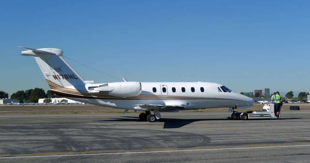
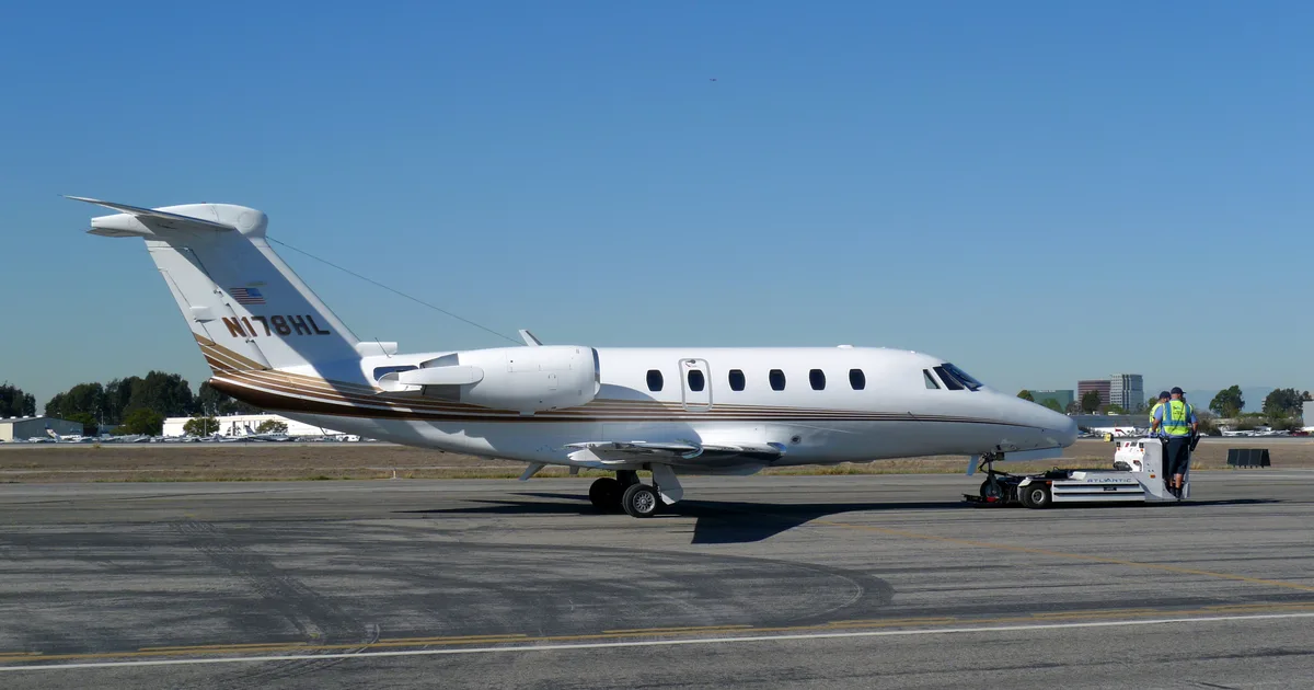


In this document
Weight Limitations
The Cessna Citation VI has specific weight limitations: Maximum Design Ramp Weight is 14,070 pounds, Maximum Design Takeoff Weight is 13,870 pounds, Maximum Design Landing Weight is 12,750 pounds, and Maximum Design Zero Fuel Weight is 10,510 pounds. The takeoff weight must comply with the most restrictive requirements, including certified takeoff weight and climb performance requirements.
Center-of-Gravity Limits
The center-of-gravity limits for the Cessna Citation VI are defined in a specific envelope, which must be adhered to for safe operation. The loading schedule must be approved and followed to ensure the aircraft remains within these limits.
Engine Operating Limits
The document specifies engine operating limits, including inter-turbine temperature (ITT) limits and thrust settings. For takeoff, the maximum continuous thrust is defined, and various temperature and pressure limits are outlined to ensure safe engine operation.
Speed Limitations
Maximum operating limit speeds for the Citation VI include MMO (0.737 Mach above 29,300 feet) and VMO (278 KIAS between 8,000 and 29,300 feet, 260 KIAS below 8,000 feet). Additionally, maximum maneuvering speeds and flap extended speeds are detailed.
Takeoff and Landing Operational Limits
Operational limits for takeoff and landing include a maximum altitude limit of 10,000 feet, maximum tailwind component of 10 knots, and specific temperature requirements for cabin conditions prior to takeoff. The document also outlines conditions under which takeoff is prohibited, such as contamination on critical surfaces.
Safety notes
- Compliance with certification and operational limitations is mandatory at all times.
- Takeoff is prohibited with an ENG CTRL SYS FAULT caution light illuminated.
- Takeoffs and landings are limited to paved runway surfaces.
Full document text
SECTION II - OPERATING LIMITATIONS MODEL 525B OPERATING LIMITATIONS CERTIFICATION STATUS This airplane is certified in accordance with 14 CFR, Part 23 Commuter Category, Part 34 (Fuel Venting and Exhaust Emissions), Part 36 (Noise Requirements) and Special Conditions as prescribed by the Administrator. WEIGHT LIMITATIONS Maximum Design Ramp Weight . . . . . . . . . . . . . . . . . . . . . . . . . . . . . . . 14,070 Pounds Maximum Design Takeoff Weight . . . . . . . . . . . . . . . . . . . . . . . . . . . . . . 13,870 Pounds Maximum Design Landing Weight . . . . . . . . . . . . . . . . . . . . . . . . . . . . . 12,750 Pounds Maximum Design Zero Fuel Weight . . . . . . . . . . . . . . . . . . . . . . . . . . . . 10,510 Pounds Takeoff weight is limited by the most restrictive of the following requirements: Maximum Certified Takeoff Weight . . . . . . . . . . . . . . . . . . . . . . . . . 13,870 Pounds Maximum Takeoff Weight Permitted by Climb Requirements . . . . . . . . . . . . . . . . . . . . Refer to Procedures for Use of Takeoff Performance Tables in Section IV Takeoff Field Length . . . . . . . . . . . . . . . . . Refer to Procedures for Use of Takeoff Performance Tables in Section IV Landing weight is limited by the most restrictive of the following requirements: Maximum Certified Landing Weight . . . . . . . . . . . . . . . . . . . . . . . . . 12,750 Pounds Maximum Landing Weight Permitted by Climb Requirements or Brake Energy Limit . . . . . . . . . . . . Refer to Procedures for Use of Approach and Landing Performance Tables in Section IV Landing Distance . . . . . . . . . . . . . . . . . Refer to Procedures for Use of Approach and Landing Performance Tables in Section IV CENTER-OF-GRAVITY LIMITS Center-of-Gravity Limits Envelope . . . . . . . . . . . . . . . . . . . . . . . . . . Refer to Figure 2-1 WEIGHT AND BALANCE DATA The airplane must be operated in accordance with the approved loading schedule. (Refer to Weight and Balance Data in Section VI.) CERTIFICATION AND OPERATIONAL LIMITATIONS ARE CONDITIONS OF THE TYPE AND AIRWORTHINESS CERTIFICATES AND MUST BE COMPLIED WITH AT ALL TIMES AS REQUIRED BY LAW NOTICE FAA APPROVED 525BFM-00 Configuration AA U.S. 2-3 SECTION II - OPERATING LIMITATIONS MODEL 525B Figure 2-1 FAA APPROVED 2-4 U.S. Configuration AA 525BFM-00 SECTION II - OPERATING LIMITATIONS MODEL 525B POWERPLANT LIMITATIONS Engine Type . . . . . . . . . . . . . . . . . . . . . . . . . Williams International FJ44-3A Turbofan Engine Operating Limits . . . . . . . . . . . . . . . . . . . . . . . . . . . . . . . . . . Refer to Figure 2-2 Engine Inter-Turbine Temperature (ITT) Limits . . . . . . . . . Refer to Figures 2-3 and 2-4 Engine Overspeed Limits . . . . . . . . . . . . . . . . . . . . . . . . . Refer to Figures 2-5 and 2-6 Takeoff/Go-Around Thrust (TO Detent) . . . . . . . . . . . . . . . . Refer to Figure 4-8 and 4-9 Maximum Continuous Thrust Single-Engine (MCT Detent) . . . . . . Refer to Figures 4-10 Maximum Continuous Thrust Multi-Engine (MCT Detent) . . . . . . . . Refer to Figure 4-11 ENGINE OPERATING LIMITS NOTE 1. Takeoff thrust settings that are nominally limited to 5 minutes duration may be used for up to 10 minutes for One Engine Inoperative operations. Time limit begins when throttle lever is advanced for takeoff thrust. The takeoff thrust (N1) for the airplane is defined in Figure 4-8 and 4-9, and is more limiting than engine rotational limits and must be observed. Performance data, including VMCA and VMCG in Section IV, is based on use of the takeoff thrust setting. 2. Maximum continuous thrust (MCT) for the airplane is defined by Figures 4-10 (single-engine) and Figure 4-11 (multi-engine). These thrust settings (N1) are more limiting than engine rotational limits and must be observed. Performance data in Section IV is based on the use of the appropriate MCT setting. 3. Minimum oil pressure is 45 PSIG when operating at or above 80% N2; 35 PSIG when operating below 80% N2. 4. Minimum allowable oil pressure is 23 PSIG for up to 5 minutes when operating below 80% N2. 5. Maximum allowable oil pressure is 100 PSIG for up to 5 minutes when operating at or above 80% N2. 6. Maximum allowable oil pressure is 100 PSIG for up to 5 minutes with oil pressure returning to normal range. 7. The engine should not be operated above 80% N2 until oil temperature is above 10°C (+50°F). 8. Maximum oil temperature is 149°C (+300°F) for up to 5 minutes when operating below 80% N2. Figure 2-2 OPERATING CONDITIONS OPERATING LIMITS THRUST SETTING TIME LIMIT (MINUTES) ITT TEMPERATURE °C N 2 % TURBINE RPM N1 % FAN RPM OIL PRESSURE PSIG OIL TEMPERATURE °C START REFER TO FIGURE 2-4 -40 TO 135 (NOTE 7) GND IDLE CONTINUOUS 53.4 (MIN) 35 MIN. 100 MAX (NOTE 6) -40 TO 135 (NOTE 7) FLT IDLE CONTINUOUS 60.7 (MIN) 35 MIN. 100 MAX (NOTE 6) -40 TO 135 (NOTE 7) TAKEOFF 5 (NOTE 1) 877 MAX. 100.0 102.8 (NOTE 1) 45 - 90 (NOTE 3) 10 - 135 MAXIMUM CONTINUOUS CONTINUOUS 840 MAX. 100.0 102.8 (NOTE 2) 45 - 90 (NOTE 3) 10 - 135 TRANSIENT --- REFER TO FIGURE 2-3 100.7 (20 SEC MAX) 103.9 (20 SEC MAX) 23 MIN. (NOTE 4) 100 MAX. (NOTE 5) 149 (NOTE 8) FAA APPROVED 525BFM-00 Configuration AA U.S. 2-5 SECTION II - OPERATING LIMITATIONS MODEL 525B INTER-TURBINE TEMPERATURE (ITT) LIMITS (EXCEPT STARTING OR SHUTDOWN) NOTE Zone 1: Determine and correct the cause of overtemperature. Zone 2: Perform inspection of hot section, (Ref. Maintenance Manual 71-00-01, P.B. 601) including NDI of HP turbine rotor assembly (Ref. Maintenance Manual 70-42-15, P.B. 601). If visual inspection reveals indications of overtemperature, disassemble LP turbine module and perform NDI inspection on LP turbine assembly. Figure 2-3 FAA APPROVED 2-6 U.S. Configuration AA 525BFM-00 SECTION II - OPERATING LIMITATIONS MODEL 525B INTER-TURBINE TEMPERATURE (ITT) LIMITS
Show full textShow less
(STARTING AND SHUTDOWN) NOTE Zone 1: Determine and correct the cause of overtemperature. Zone 2: 1. Perform a boroscope inspection on the HP turbine area (Ref. Maintenance Manual 71-00-40, P.B. 601). 2. Perform a performance check ground run test (Ref. Maintenance Manual 71-00-00, P.B. 501). Zone 3: Perform inspection of hot section, (Ref. Maintenance Manual 71-00-01, P.B. 601) including NDI of HP turbine rotor assembly (Ref. Maintenance Manual 70-42-15, P.B. 601). If visual inspection reveals indications of overtemperature, disassemble LP turbine module and perform NDI inspection on LP turbine assembly. Figure 2-4 FAA APPROVED 525BFM-00 Configuration AA U.S. 2-7 SECTION II - OPERATING LIMITATIONS MODEL 525B N2 ENGINE OVERSPEED LIMITS NOTE Zone 1: Determine and correct the cause of overspeed. Zone 2: Perform inspection of hot section, (Ref. Maintenance Manual 71-00-01, P.B. 601) including NDI of HP turbine rotor assembly (Ref. Maintenance Manual 70-42-15, P.B. 601). If visual inspection reveals indications of overtemperature, disassemble LP turbine module and perform NDI inspection on LP turbine assembly. Zone 3: Return to approved facility for inspection of compressor zone (Ref. Engine Manual 72-00-00, P.B. 801). Figure 2-5 FAA APPROVED 2-8 U.S. Configuration AA 525BFM-02 SECTION II - OPERATING LIMITATIONS MODEL 525B N1 ENGINE OVERSPEED LIMITS NOTE Zone 1: Determine and correct the cause of overspeed. Zone 2: Perform inspection of the first LP turbine rotor (Ref. Engine Manual 72-55-31, P.B. 801) and second LP turbine rotor (Ref. Engine Manual 72-55-33, P.B. 801). Above 110% N1, return to approved facility for inspection of compressor zone (Ref. Engine Manual 72-00-00, P.B. 801). Figure 2-6 FAA APPROVED 525BFM-00 Configuration AA U.S. 2-9 SECTION II - OPERATING LIMITATIONS MODEL 525B ENGINE START LIMITATIONS (Ground) ENG CTRL SYS FAULT L/R Annunciators . . . . . . . . . . . . . . . . . . . . . . . . Extinguished Inter-Turbine Temperature (ITT) Limits . . . . . . . . . . . . . . . . . . . . . . . Refer to Figure 2-4 Maximum Tailwind Component . . . . . . . . . . . . . . . . . . . . . . . . . . . . . . . . . . . 12 Knots Maximum Crosswind Component . . . . . . . . . . . . . . . . . . . . . . . . . . . . . . . . . 16 Knots Maximum Time to Light-off . . . . . . . . . . . . . . . . . . . . . . . . . . . . . . . . . . . . . 10 Seconds NOTE Time to light-off is defined as the time after the throttle lever is moved from OFF to IDLE position until light-off is indicated. Minimum Engine Oil Temperature (indicated on EIS) . . . . . . . . . . . . . . . . . . . . . -40°C NOTE f If engine oil temperature is below -40°C (-40°F), the engine must be preheated prior to conducting a start. f If the battery has been cold soaked for 2 hours or longer at ambient surface temperature of -18°C (0°F) or lower, it must be preheated to above -18°C (0°F) prior to start. f The Engine Indicating System (EIS) may take 1 to 6 minutes to become usable after power is applied when cold soaked below -10°C (+14°F). f Successful power-up of the FADECS (by selecting Battery Switch to BATT) has been demonstrated down to -40°C (-40°F) surface temperature. If surface temperature is below -40°C (-40°F), the FADEC units may generate non-resettable ENG CTRL SYS FAULT annunciations upon power-up. Engine start with an ENG CTRL SYS FAULT annunciator illuminated is prohibited. Refer to COLD WEATHER OPERATIONS in Section III, Normal Procedures. Maximum Temperature For Engine Start . . . . . . . . . . . . . . . . . . . . . Refer to Figure 2-9 Maximum Airport Elevation For Ground Battery Start . . . . . . . . . . . . . . . . . 10,000 Feet Maximum Airport Elevation For Ground External Power Start . . . . . . . . . . . 10,000 Feet Minimum Battery Voltage For Battery Start . . . . . . . . . . . . . . . . . . . . . . . . . . . . 24 VDC Minimum/Maximum External Power Current Capacity For Start . . . . . . 800/1100 AMPS NOTE Normal starter current draw is approximately 1000 amperes peak. External power units with variable maximum current shutoff should be set to 1100 amperes. Use of an external power source with voltage in excess of 29VDC or current in excess of 1100 amps may damage the starter. ENGINE START LIMITATIONS (Air) Inter-Turbine Temperature (ITT) Limits . . . . . . . . . . . . . . . . . . . . . . . Refer to Figure 2-4 Airspeed/Altitude Limits (Airstart Envelope) . . . . . . . . . . . . . . . . . . . Refer to Figure 3-1 ENGINE FAN INSPECTION Prior to engine start, the Engine Fan Duct and Fan inspection in Section III, Normal Procedures, must be satisfactorily completed. FAA APPROVED 2-10 U.S. Configuration AA 525BFM-02 SECTION II - OPERATING LIMITATIONS MODEL 525B STARTER CYCLE LIMITATIONS Starter Cycle Limitation . . . . Three engine starts per 30 minutes. Three cycles of operation with a 60-second rest period between cycles is permitted. NOTE This limitation is independent of starter power source; i.e., battery, generator assisted cross start, or external power unit. BATTERY LIMITATIONS The battery temperature warning system must be operational for all ground and flight operations. The battery temperature warning system preflight test (on the Rotary TEST Switch) in Section III, Normal Procedures, must be satisfactorily completed. If the BATT O'TEMP warning light illuminates during ground operation, do not take off until the proper maintenance procedures have been accomplished. Battery Cycle Limitations: Three engine starts per hour. NOTE f If battery limitation is exceeded, ground maintenance procedures are required. Refer to Chapter 24 of the Maintenance Manual for procedure. f Three generator assisted cross starts are equal to one battery start. f If an external power unit is used for start, no battery cycle is counted. GROUND OPERATION Continuous engine ground static operation up to and including five minutes at takeoff thrust is limited to ambient temperatures defined in Figure 2-9. Maximum Generator Current (per generator) . . . . . . . . . . . . . . . . . . . . . 200 Amperes Limit ground operation of pitot/static heat to two minutes to preclude damage to the pitot tubes and angle of attack vane. Ground operation at greater than 75% N 2 engine RPM with engine, wing, and/or windshield anti-ice on is limited to two minutes. Do not operate with the wing anti-ice on more than one minute after the WING ANTI-ICE L/R annunciators have extinguished. Ambient surface temperature must be obtained from the RAT display at the bottom of each PFD, with either or both engines operating, or from an appropriate ground station. The SAT display is unreliable on the ground. WINDSHIELD ICE PROTECTION FLUID Use TT-I-735 isopropyl alcohol for windshield anti-ice. HYDRAULIC FLUID Use MIL-PRF-83282 Type fluids only. FAA APPROVED 525BFM-04 Configuration AA U.S. 2-11 SECTION II - OPERATING LIMITATIONS MODEL 525B FUEL LIMITATIONS Fuel Boost Pumps - ON; when FUEL LOW LEVEL L and/or R caution lights illuminate or at 210 pounds or less indicated fuel. NOTE If fuel transfer is required, VERIFY the fuel boost pump is not operating on the side to which the fuel is being transferred. (For example, to transfer from left tank to right tank, verify right boost pump is not operating). Refer to Figure 2-7 for fuels that are approved for use. Maximum approved fuel imbalance is 200 lbs. A fuel imbalance of 600 lbs. has been demonstrated for emergency return. FUEL LIMITATIONS NOTE f Dupont Stadis 450 antistatic additive or equivalent is permitted to bring fuel up to 300 conductive units, but not to exceed 1 ppm (parts per million). f SOHIO Biobor JF biocide additive is approved at a concentration not to exceed 20 ppm (270 ppm total additive) of elemental boron. f EGME/DIEGME additive is approved for use, but not required, at a concentration not to exceed 0.15 percent volume. Refer to Normal Procedures, ANTI-ICE ADDITIVES for blending instructions. Figure 2-7 APPROVED OILS NOTE Mixing of approved oils is permissible. UNUSABLE FUEL Fuel remaining in the fuel tanks when the fuel quantity indicator reads zero is not usable in flight. GRADE (TYPE) (REFER NOTE BELOW) SPECIFICATION MINIMUM FUEL TEMPERATURE °C (°F) MAXIMUM FUEL TEMPERATURE °C (°F) JET A JET A1 ASTM-D1655 -40 (-40) -40 (-40) +57.2 (+135) +57.2 (+135) JP-5 MIL-PRF-5624 -40 (-40) +57.2 (+135) JP-8 MIL-T-83133 -40 (-40) +57.2 (+135) APPROVED BRAND SPECIFICATION Mobil Jet II MIL-L-23699 Mobil 254 MIL-L-23699 FAA APPROVED 2-12 U.S. Configuration AA 525BFM-04 SECTION II - OPERATING LIMITATIONS MODEL 525B SPEED LIMITATIONS Maximum Operating Limit Speeds MMO (Above 29,300 Feet) . . . . . . . . . . . . . . . . . . . . . . . . . 0.737 Mach (Indicated) V MO (Between 8000 and 29,300 Feet) . . . . . . . . . . . . . . . . . . . . . . . . . . . 278 KIAS V MO (Below 8000 Feet) . . . . . . . . . . . . . . . . . . . . . . . . . . . . . . . . . . . . . . 260 KIAS The maximum operating limit speeds may not be deliberately exceeded in any regime of flight (climb, cruise or descent) unless a higher speed is authorized for flight test or pilot training. Maximum Maneuvering Speeds - V A . . . . . . . . . . . . . . . . . . . . . . . . Refer to Figure 2-8 Full application of rudder and aileron controls as well as maneuvers that involve angle-of- attack near the stall should be confined to speeds below maximum maneuvering speed. Refer to LOAD FACTOR limitations for pitch maneuvering limitations. Maximum Flap Extended Speed - VFE TAKEOFF AND APPROACH Position (15°) . . . . . . . . . . . . . . . . . . . . . . . 200 KIAS LAND Position (35°) . . . . . . . . . . . . . . . . . . . . . . . . . . . . . . . . . . . . . . . . 161 KIAS Maximum Speed With Flaps Failed to Ground Flaps (55°) . . . . . . . . . . . 140 KIAS Maximum Landing Gear Extended Speed - VLE . . . . . . . . . . . . . . . . . . . . . . . 250 KIAS Maximum Landing Gear Operating Speed - VLO (Extending) . . . . . . . . . . . . . 250 KIAS Maximum Landing Gear Operating Speed - V LO (Retracting) . . . . . . . . . . . . . 200 KIAS Maximum Speed Brake Operation Speed - V SB . . . . . . . . . . . . . . . . . . . . . . . . No Limit Maximum Autopilot Operation Speed . . . . . . . . . . . . . . . . . . . 278 KIAS or 0.737 Mach NOTE For minimum control speeds (VMCA and VMCG), refer to the respective definition in Section IV, Performance - General. GROUND FLAPS LIMITATIONS Intentional selection of Ground Flaps in flight is prohibited. WARNING THE GROUND FLAPS POSITION IS NOT LOCKED OUT IN FLIGHT. SELECTION OF GROUND FLAPS WILL SIGNIFICANTLY INCREASE DRAG AND SINK RATE. TAKEOFF AND LANDING OPERATIONAL LIMITS Maximum Altitude Limit . . . . . . . . . . . . . . . . . . . . . . . . . . . . . . . . . . . . . . . 10,000 Feet Maximum Tailwind Component . . . . . . . . . . . . . . . . . . . . . . . . . . . . . . . . . . . 10 Knots Maximum Ambient Temperature . . . . . . . . . . . . . . . . . . . . . . . . . . . Refer to Figure 2-9 Minimum Ambient Temperature . . . . . . . . . . . . . . . . . . . . . . . . . . . . . . . -54°C (-65°F) The maximum approved fuel imbalance is 200 pounds; however, controllability for safe return and landing has been demonstrated with an emergency fuel imbalance of 600 pounds. Cabin temperature must be held at or above 0°C (+32°F) for a minimum of 20 minutes prior to takeoff after a prolonged ground cold soak period (two hours or longer) at ambient temperatures of -10°C (+14°F) or colder (refer to Normal Procedures, COLD WEATHER OPERATIONS. This temperature ensures proper deployment and operation of the passenger oxygen masks. A handheld thermometer is acceptable to determine cabin temperature. This limitation does not apply if there are no passengers in the cabin. (Continued Next Page) FAA APPROVED 525BFM-02 Configuration AA U.S. 2-13 SECTION II - OPERATING LIMITATIONS MODEL 525B TAKEOFF AND LANDING OPERATIONAL LIMITS (Continued) Prior to takeoff, the following systems must be operational and must have satisfactorily completed the preflight checks in Section III, Normal Procedures: The Angle-of-Attack and Stall Warning System, Electric Elevator Trim, Rudder Bias, Flaps, and Flight Controls. In addition, channels A and B of the L and R FADECS must be verified operational prior to takeoff. Takeoff is prohibited with an ENG CTRL SYS FAULT L/R caution light illuminated. The autopilot and yaw damper must be OFF for takeoff and landing. Engine synchronizer must be OFF for takeoff and landing. Takeoff is prohibited if the antiskid system is inoperative. Cabin must be depressurized for takeoff and landing. Takeoffs and landings are limited to paved runway surfaces. Speed brakes must be retracted prior to 50 feet AGL before landing. Extending ground flaps during touch and go landings is prohibited. The GROUND IDLE switch must be in the HIGH position when conducting touch and go landings. For normal takeoff operations, the GROUND IDLE switch must be in the NORMAL position. Goodyear tire part number 184F08-1 and Michelin tire part number 031-613-8 are the only nose tires approved. The nose tire must be inflated to 125 PSI ±5 PSI (loaded), or 120 PSI ±5 PSI (unloaded). Goodyear tire part number 229K28-2 and Michelin tire part number 026-618-0 are the only main gear tires approved. Installed main gear tires must be of the same brand. The main gear tires must be inflated to 137 PSI ±3 PSI (loaded), or 132 PSI ±3 PSI (unloaded). Maximum Tire Ground Speed . . . . . . . . . . . . . . . . . . . . . . . . . . . . . . . . . . . 165 Knots Takeoff is prohibited with the following forms of contamination: 1. With frost adhering to the following critical areas: f Wing Leading Edge f Upper Wing Surface f Windshield 2. With ice, snow, or slush adhering to the following critical areas: f Wing Leading Edge and Upper Wing Surface f Flight Control Surfaces including all hinge gaps f Horizontal Stabilizer f Vertical Stabilizer f Engine Inlets f Top of Engine Pylons f Top of Fuselage (Continued Next Page) FAA APPROVED I2-14 U.S. Configuration AA 525BFM-04 SECTION II - OPERATING LIMITATIONS MODEL 525B TAKEOFF AND LANDING OPERATIONAL LIMITS (Continued) f Windshield f All Static Ports f Angle of Attack Vanes f Upper surface of nose forward of the windshield NOTE Refer to Section VII for information regarding Ground Deicing and Anti-icing procedures. 3. A visual and tactile (hand on surface) check of the wing leading edge and wing upper surface must be performed to ensure the wing is free from frost, ice, snow, or slush when the outside air temperature is less than 10°C (50°F) or if it cannot be determined that the wing fuel temperature is above 0°C (32°F) and any of the following conditions exist: a. There is visible moisture present (rain, drizzle, sleet, snow, fog, etc.); or b. Water is present on the upper wing surface; or c. The difference between the dew point and the outside air temperature is 3°C (5°F) or less; or d. The atmospheric conditions have been conducive to frost formation. ENROUTE OPERATIONAL LIMITS Maximum Operating Altitude . . . . . . . . . . . . . . . . . . . . . . . . . . . . . . . . . . . 45,000 Feet NOTE The cabin must be heated to a temperature of 0°C (+32°F) prior to operation above 24,000 feet. This temperature ensures proper deployment and operation of the passenger oxygen masks. A handheld thermometer is acceptable to determine cabin temperature. This limitation does not apply if there are no passengers in the cabin. Maximum Ambient Temperature . . . . . . . . . . . . . . . . . . . . . . . . . . . Refer to Figure 2-9 Minimum Ambient Temperature . . . . . . . . . . . . . . . . . . . . . . . . . . . . Refer to Figure 2-9 Maximum Generator Current (per generator) . . . . . . . . 300 Amperes Up to 41,000 Feet 250 Amperes above 41,000 Feet Maximum altitude for extension of flaps and/or landing gear . . . . . . . . . . . 18,000 Feet Maximum operating altitude with inoperative Yaw Damper . . . . . . . . . . . . . 29,000 Feet FAA APPROVED I525BFM-04 Configuration AA U.S. 2-15 SECTION II - OPERATING LIMITATIONS MODEL 525B MAXIMUM MANEUVERING SPEEDS AVOID RAPID AND LARGE ALTERNATING CONTROL INPUTS, ESPECIALLY IN COMBINATION WITH LARGE CHANGES IN PITCH, ROLL, OR YAW (I.E., LARGE SIDESLIP ANGLES) AS THEY MAY RESULT IN STRUCTURAL FAILURES AT ANY SPEED, INCLUDING BELOW VA. EXAMPLE: Pressure Altitude - 27,500 FEET Weight - 10,000 POUNDS Maximum Maneuvering Speed - 180 KIAS Figure 2-8 WARNING FAA APPROVED I2-16 U.S. Configuration AA 525BFM-04 SECTION II - OPERATING LIMITATIONS MODEL 525B Figure 2-9 NOTE Maximum and Minimum Temperature Limits are the Ambient Air Temperature from Figure 2-9. In flight, ambient air temperature is obtained from the Static Air Temperature (SAT) display at the bottom of each PFD. On ground, ambient air temperature is obtained from the RAT display (with at least one engine running) or an appropriate ground station. (Continued Next Page) TAKEOFF/LANDING/ENROUTE TEMPERATURE LIMITATIONS FAA APPROVED I525BFM-04 Configuration AA U.S. 2-17 SECTION II - OPERATING LIMITATIONS MODEL 525B OPERATIONS AUTHORIZED This airplane is approved for day and night, VFR and IFR operations, and flight into known icing conditions when the required equipment is installed as defined within the Kinds of Operations Equipment List. Acrobatic maneuvers, including spins, are prohibited. Intentional stalls are prohibited above 18,000 feet. MINIMUM CREW Except where otherwise prescribed by applicable operating limitations, Minimum crew for all operations: 1 Pilot, provided: a. The pilot holds a CE525(S), single pilot, type rating. b. The airplane is equipped for single pilot operation as specified in the Kinds of Operations Equipment List. c. The pilot must occupy the left pilot’s seat. Or 1 Pilot and 1 Copilot provided: a. The pilot in command holds a CE525(S) or CE525 (second-in-command required) type rating. LOAD FACTOR In Flight Flaps UP Position (0°) . . . . . . . . . . . . . . . . . . . –1.44 to +3.6G at 13,870 Pounds Flaps TAKEOFF AND APPROACH to LAND Position (15° to 35°) . . . . . . . . . . . . . . . . . . . . . . . . . . 0.0 to +2.0G at 13,870 Pounds These accelerations limit the angle-of-bank in turns and limit the severity of pull-up and push-over maneuvers. CABIN PRESSURIZATION LIMITATIONS Normal Cabin Pressurization Limitations . . . . . . . . 0.0 to 8.9 PSI ± 0.1 PSI Differential PASSENGER SEATING For all takeoffs and landings, adjustable seats must be fully upright and outboard and passenger seat belts and shoulder harnesses must be fastened. Maximum passenger seating, not including 2 crew seats, is seven (eight with optional belted toilet installed). FAA APPROVED I2-18 U.S. Configuration AA 525BFM-04 SECTION II - OPERATING LIMITATIONS MODEL 525B INSTRUMENT MARKINGS ENGINE INDICATING SYSTEM FAN (N 1) RPM INDICATORS Scale Markings . . . . . . . . . . . . . . . . . Red Line 102.9% RPM Tape/Pointer/Digital Readout . . . . . . . Red f104.0% RPM 102.9 - 103.9% RPM for f20 Sec Yellow 102.9 - 103.9% RPM for < 20 Sec Tape/Pointer . . . . . . . . . . . . . . . . . . . . White e102.8% RPM Digital Readout . . . . . . . . . . . . . . . . . . Green e102.8% RPM NOTE f Tape, Pointer and Digital Readout will turn red or yellow if outside normal operating limits. f Pointer and Digital Readout will flash for 5 seconds and then remain steady if outside normal operating limits. f White Tape Pointer represents Green band. INTER-TURBINE TEMPERATURE INDICATORS Engine Start Scale Markings . . . . . . . . . . . . . . . . . Red Triangle 1001°C Red Line 878°C Yellow Band 841°C - 877°C Tape/Pointer . . . . . . . . . . . . . . . . . . . . Red >1000°C White e1000°C NOTE f Tape will turn red and Pointer will flash red for five seconds and then remain steady red if outside normal starting operating limits. f Engine Running Red Line and Yellow Band do not apply while ITT Start Limit (Red Triangle) is in view. f White Tape Pointer represents Green band. (Continued Next Page) FAA APPROVED I525BFM-04 Configuration AA U.S. 2-19 SECTION II - OPERATING LIMITATIONS MODEL 525B INSTRUMENT MARKINGS (Continued) One Engine Running Scale Markings . . . . . . . . . . . . . . . . . Red Line 878°C Yellow Band 841°C - 877°C Tape/Pointer . . . . . . . . . . . . . . . . . . . . Red f878°C 841°C - 877°C for f10min Yellow 841°C - 877°C for f3 min, <10min White e840°C 841°C - 877°C for <3min NOTE f Tape will turn red or yellow, the Pointer will flash red or yellow for five seconds and then remain steady if outside normal operating limits. f White Tape Pointer represents Green band. Two Engines Running Scale Markings . . . . . . . . . . . . . . . . . Red Line 878°C Yellow Band 841°C - 877°C Tape/Pointer . . . . . . . . . . . . . . . . . . . . Red f878°C 841°C - 877°C for f5 min Yellow 841°C - 877°C for f3 min, <5 min White e840°C 841°C - 877°C for <3 min NOTE f Tape will turn red or yellow, the Pointer will flash red or yellow for five seconds and then remain steady if outside normal operating limits. f White Tape Pointer represents Green band. (Continued Next Page) FAA APPROVED I2-20 U.S. Configuration AA 525BFM-04 SECTION II - OPERATING LIMITATIONS MODEL 525B INSTRUMENT MARKINGS (Continued) TURBINE (N 2) RPM INDICATORS Digital Readout . . . . . . . . . . . . . . . . . . Red f100.8% RPM 100.1 - 100.7% f20 sec Yellow 100.1 - 100.7% < 20 sec Green e100.0% RPM NOTE Digital Readout will flash red or yellow for five seconds and then remain steady if outside normal operating limits. OIL TEMPERATURE INDICATORS Scale Markings . . . . . . . . . . . . . . . . . Red Band f150°C Upper Yellow Band 136°C - 149°C Lower Yellow Band e9°C Green Band 10°C - 135°C Pointer . . . . . . . . . . . . . . . . . . . . . . . . Red f150°C 136°C - 149°C f 5 min Yellow 136°C - 149°C < 5 min e9°C Green 10°C - 135°C Digital Readout . . . . . . . . . . . . . . . . . . Red f150°C 136°C - 149°C f 5 min Yellow 136°C - 149°C <5 min e9°C NOTE f Pointer and Digital Readout will flash red or yellow for five seconds and then remain steady if outside normal operating limits. f Digital Readout is displayed only when temperature is outside normal operating limits. OIL PRESSURE INDICATORS Scale Markings . . . . . . . . . . . . . . . . . Red Band e22 PSI f101 PSI Yellow Band 23 - 34 PSI 91 - 100 PSI Green Band 35 - 90 PSI NOTE Oil Pressure Indicator Scale Markings do not change with varying N2. N2 < 80% Pointer . . . . . . . . . . . . . . . . . . . . . . . . Red e22 PSI 23 - 34 PSI f 5 min 91 - 100 PSI f 5 min f101 PSI Yellow 23 - 34 PSI <5 min 91 - 100 PSI <5 min Green 35 - 90 PSI (Continued Next Page) FAA APPROVED I525BFM-04 Configuration AA U.S. 2-21 SECTION II - OPERATING LIMITATIONS MODEL 525B INSTRUMENT MARKINGS (Continued) OIL PRESSURE INDICATORS (Continued) Digital Readout Red e22 PSI 23 - 34 PSI f 5 min 91 - 100 PSI f 5 min f 101 PSI Yellow 23 - 34 PSI <5 min 91 - 100 PSI <5 min N 2 f 80% Pointer . . . . . . . . . . . . . . . . . . . . . . . . Red e44 PSI 91 - 100 PSI f 5 min f101 PSI Yellow 91 - 100 PSI <5 min Green 45 - 90 PSI Digital Readout Red e44 PSI 91 - 100 PSI f 5 min f 101 PSI Yellow 91 - 100 PSI <5 min NOTE f Pointer and Digital Readout will flash red or yellow for five seconds and then remain steady if outside normal operating limits, with one exception: For oil pressure 91-100 PSI, the pointer will change to yellow but digits will not be displayed until 4 minutes have elapsed, at which time both yellow digits and pointer will flash for 5 seconds then remain steady. f Digital Readout is displayed only when pressure is outside normal operating limits. OTHER INSTRUMENTS Airspeed Indicator . . . . . . . . . . . . . . . . . . . . . . . . . . Red Line: 278 KIAS (0.737 MACH) 260 KIAS (Below 8000 Feet) Ammeter Indicators . . . . . . . . . . . . . . . . . . . . . . . . . . . . . . . . . . . Red Line: 300 Amps Yellow Arc: 250 - 300 Amps Cabin Differential Pressure Indicator . . . . . . . . . . . . . . . . . . . . . . Red Line :> 8.9 PSI Green Arc: 0.0 - 8.9 PSI Oxygen Pressure Indicator . . . . . . . . . . . . . . . . . . . . . . . . . . . . . . Red Line: 2000 PSI Yellow Arc: 0 - 400 PSI Green Arc:1600 - 1800 PSI Brake and Gear Pneumatic Pressure . . . . . . . . . . . . . . . . Wide Red Arc: > 2050 PSI Indicator Narrow Red Arc: 0 - 1600 PSI Wide Yellow Arc: 1600 - 1800 PSI Wide Green Arc: 1800 - 2050 PSI Brake Hydraulic Accumulator . . . . . . . . . . . . . . . . . . Narrow Red Arc: Underpressure Pressure Indicator Light Green Arc: Precharge Pressure Yellow Arc: Caution Wide Green Arc: Normal Operating Range Wide Red Arc: Overpressure FAA APPROVED I2-22 U.S. Configuration AA 525BFM-04 SECTION II - OPERATING LIMITATIONS MODEL 525B ROCKWELL COLLINS FCS-3000 INTEGRATED FLIGHT CONTROL SYSTEM The Rockwell Collins Pro Line 21 Avionics System Operator's Guide for Cessna Citation CJ3 Publication Number 523-0806480, Edition 1 (1 is a variable and changes with revision number), dated 30 April 2004 or later revision, must be immediately available to the flight crew. 1. One pilot must remain seated with seat belt fastened during all autopilot operations. 2. Operating in the composite mode is limited to training and display failure conditions. 3. The pilot's PFD, copilot's PFD and MFD must be installed and operational in the normal mode for takeoff. 4. The FCS-3000 system must be verified to be operational by a satisfactory automatic preflight test (no messages on power up) prior to each flight in which the autopilot is to be used. 5. The autopilot minimum engage height, during climb following takeoff or go-around, is 350 feet AGL. 6. The autopilot minimum use height is: a. ILS Approach (CAT I) 180 Feet AGL b. Non-precision Approaches 350 Feet AGL c. Cruise 1000 Feet AGL 7. Category II approaches are not approved. 8. VOR approaches must be conducted in the APPR mode. 9. Autopilot coupled VOR approaches are prohibited. 10. It is prohibited to display the non-coupled side Flight Director unless the coupled side Flight Director is being displayed. Failure to adhere to this limitation will result in incorrect Flight Director guidance. Use of the coupled side Flight Director by itself will operate correctly. STANDBY FLIGHT DISPLAY A satisfactory preflight test must be accomplished on the standby flight display in accordance with Section III, Normal Procedures. The standby flight display must be functioning prior to takeoff. OXYGEN MASK Prior to flight, the EROS oxygen mask must be checked and stowed properly in its receptacle to qualify as a quick donning oxygen mask. Cabin temperature must be held at or above 0°C (+32°F) for a minimum of 20 minutes prior to takeoff after a prolonged ground cold soak period (two hours or longer) at ambient temperatures of -10°C (+14°F) or colder (refer to Normal Procedures, COLD WEATHER OPERATIONS. This temperature ensures proper deployment and operation of the passenger oxygen masks. FAA APPROVED I525BFM-04 Configuration AA U.S. 2-23 SECTION II - OPERATING LIMITATIONS MODEL 525B OXYGEN MASK (Continued) NOTE f Headsets or hats worn by the crew may interfere with the quick donning capability of the oxygen mask. f Unless carefully trimmed, mustaches and/or beards worn by crew members may interfere with proper sealing of the oxygen mask. Mask fit and seal should be checked on the ground prior to flight. Continuous use of the supplemental oxygen system above 25,000 feet cabin altitude, with passengers, or above 40,000 feet cabin altitude, crew only, is prohibited. For single pilot operations, a crew oxygen mask must be available for a passenger occupying the right crew seat. The mask must be checked during preflight and passenger briefed on its use. ICING LIMITATIONS NOTE f Icing conditions may exist when the indicated RAT in flight is +10°C (+50°F) or below, and visible moisture in any form is present (such as clouds, fog with visibility of one mile or less, rain, snow, sleet, or ice crystals). f Icing conditions on the ground exist when the OAT or indicated RAT is +10°C (+50°F) or below and, where surface snow, slush, ice or standing water may be ingested by the engines or freeze on engine nacelles, or engine sensor probes. Minimum airspeed for sustained flight in icing conditions (except approach and landing) is 180 KIAS. In icing conditions, operating the airplane at other than flaps 0 for an extended period of time (except approach and landing) is prohibited. Minimum engine N2 speed for effective wing anti-icing . . . . . . . . . . . . . . . . . . 75% N 2 Minimum temperature for operation of tail deicing boots (Indicated RAT) -35°C (-31°F) The WING/ENGINE ANTI-ICE switches must be ENG ON or WING/ENG for operations with indicated RAT of +10°C (+50°F) or below when flight free of visible moisture cannot be assured. Failure to observe this limitation may result in ENG CTRL SYS FAULT L/R annunciations due to ice accumulation on the engine PT2/TT2 probe. OPERATIONS IN SEVERE ICING CONDITIONS WARNING SEVERE ICING MAY RESULT FROM ENVIRONMENTAL CONDITIONS OUTSIDE OF THOSE FOR WHICH THE AIRPLANE IS CERTIFIED. FLIGHT IN FREEZING RAIN, FREEZING DRIZZLE, OR MIXED ICING CONDITIONS (SUPERCOOLED LIQUID WATER AND ICE CRYSTALS) MAY RESULT IN ICE BUILD-UP ON PROTECTED SURFACES EXCEEDING THE CAPABILITY OF THE ICE PROTECTION SYSTEM OR MAY RESULT IN ICE FORMING AFT OF THE PROTECTED SURFACES. (Continued Next Page) FAA APPROVED I2-24 U.S. Configuration AA 525BFM-04 SECTION II - OPERATING LIMITATIONS MODEL 525B OPERATIONS IN SEVERE ICING CONDITIONS (Continued) WARNING (Continued) THIS ICE MAY NOT SHED WHEN THE ICE PROTECTION SYSTEMS ARE USED AND MAY SERIOUSLY DEGRADE THE PERFORMANCE AND CONTROLLABILITY OF THE AIRPLANE. IN SOME ICING CONDITIONS, IT IS NORMAL FOR RUNBACK ICE TO EXTEND APPROXIMATELY 12 TO 18 INCHES AFT OF THE HEATED LEADING EDGE ON THE WING UPPER SURFACE AND/OR TO BUILD IN A RIDGE ON THE LOWER WING SURFACE JUST BEHIND THE HEATED LEADING EDGE. SATISFACTORY PERFORMANCE AND CONTROLLABILITY HAS BEEN DEMONSTRATED WITH THIS TYPE OF ICE ACCUMULATION AND IT SHOULD NOT BE CONSIDERED AN INDICATION OF SEVERE ICING. All wing icing inspection lights must be operative prior to flight into known or forecast icing conditions at night. Severe icing conditions that exceed those for which the airplane is certificated shall be determined by the following visual cues: 1. Unusually extensive ice accumulation on the airframe and windshield in areas not normally observed to collect ice. 2. Accumulation of ice on the upper surface of the wing that extends more than 12 to 18 inches aft of the heated leading edge. If one or more of these visual cues exist: 1. Use of the autopilot is prohibited. 2. Immediately request priority handling from Air Traffic Control to facilitate a route or altitude change to exit the icing conditions. 3. Leave flaps in current position, do not extend or retract. 4. Avoid abrupt and excessive maneuvering that may exacerbate control difficulties. 5. If unusual or uncommanded roll control movement is observed, reduce angle-of- attack. Since the autopilot, when installed and operating, may mask tactile cues that indicate adverse changes in handling characteristics, use of the autopilot is prohibited when: 1. Unusual lateral trim is required while the airplane is in icing conditions. 2. Autopilot trim warnings are encountered while the airplane is in icing conditions. KINDS OF OPERATIONS EQUIPMENT LIST This airplane may be operated in day or night, VFR or IFR, and flight into known icing conditions when the appropriate equipment is installed. The following equipment list identifies the systems and equipment upon which type certification for each kind of operation was predicated. The systems and items of equipment listed must be installed and operable unless: 1. The airplane is approved to be operated in accordance with a current Minimum Equipment List (MEL) issued by the FAA. Or; (Continued Next Page) FAA APPROVED I525BFM-04 Configuration AA U.S. 2-25 SECTION II - OPERATING LIMITATIONS MODEL 525B KINDS OF OPERATIONS EQUIPMENT LIST (Continued) 2. An alternate procedure is provided in the basic FAA Approved Airplane Flight Manual for the inoperative state of the listed equipment and all limitations are complied with. NOTE The following systems and equipment list does not include all equipment required by the FAR Parts 91 and 135 Operating Requirements. It also does not include components obviously required for the airplane to be airworthy such as wings, primary flight controls, empennage, engine, etc. (Continued Next Page) SYSTEM and/or COMPONENT KIND OF OPERATION V F R D A Y V F R N I G H T I F R D A Y I F R N I G H T I C I N G COMMENTS AVIONICS 1) VHF COM1 2) Static Wicks 3) Transponder 4) VHF NAV1 5) Cockpit Voice Recorder 6) Radio Tuning Unit * 13* * * * * * 13* * * * * 1* 13* 1* 1* * 2 1* 13* 1* 1* * 2 1* 13* 1* 1* * 2 * Or as required by operating regulation. VHF COM1 required for operations on Emergency Bus. * 15 total installed; 1 may be missing from any control surface, no more than 2 total may be missing. * Or as required by operating regulation. * O r as required by operating regulation. VHF NAV1 required for operations on Emergency Bus. * Required when six or more passenger seats are installed and operating rules require two pilots. * Both required for Standby HSI and COM1/NAV1 operations on Emergency Bus. ELECTRICAL 1) Battery 2) Battery Overheat Annunciator 3) DC Generator 4) DC Generator Annunciator 5) DC Ammeter 6) DC Voltmeter and Select Switch 1 1 2 2 2 1 1 1 2 2 2 1 1 1 2 2 2 1 1 1 2 2 2 1 1 1 2 2 2 1 FAA APPROVED I2-26 U.S. Configuration AB 525BFM-04 SECTION II - OPERATING LIMITATIONS MODEL 525B OPERATIONS IN SEVERE ICING CONDITIONS (Continued) WARNING (Continued) THIS ICE MAY NOT SHED WHEN THE ICE PROTECTION SYSTEMS ARE USED AND MAY SERIOUSLY DEGRADE THE PERFORMANCE AND CONTROLLABILITY OF THE AIRPLANE. IN SOME ICING CONDITIONS, IT IS NORMAL FOR RUNBACK ICE TO EXTEND APPROXIMATELY 12 TO 18 INCHES AFT OF THE HEATED LEADING EDGE ON THE WING UPPER SURFACE AND/OR TO BUILD IN A RIDGE ON THE LOWER WING SURFACE JUST BEHIND THE HEATED LEADING EDGE. SATISFACTORY PERFORMANCE AND CONTROLLABILITY HAS BEEN DEMONSTRATED WITH THIS TYPE OF ICE ACCUMULATION AND IT SHOULD NOT BE CONSIDERED AN INDICATION OF SEVERE ICING. All wing icing inspection lights must be operative prior to flight into known or forecast icing conditions at night. Severe icing conditions that exceed those for which the airplane is certificated shall be determined by the following visual cues: 1. Unusually extensive ice accumulation on the airframe and windshield in areas not normally observed to collect ice. 2. Accumulation of ice on the upper surface of the wing that extends more than 12 to 18 inches aft of the heated leading edge. If one or more of these visual cues exist: 1. Use of the autopilot is prohibited. 2. Immediately request priority handling from Air Traffic Control to facilitate a route or altitude change to exit the icing conditions. 3. Leave flaps in current position, do not extend or retract. 4. Avoid abrupt and excessive maneuvering that may exacerbate control difficulties. 5. If unusual or uncommanded roll control movement is observed, reduce angle-of- attack. Since the autopilot, when installed and operating, may mask tactile cues that indicate adverse changes in handling characteristics, use of the autopilot is prohibited when: 1. Unusual lateral trim is required while the airplane is in icing conditions. 2. Autopilot trim warnings are encountered while the airplane is in icing conditions. KINDS OF OPERATIONS EQUIPMENT LIST This airplane may be operated in day or night, VFR or IFR, and flight into known icing conditions when the appropriate equipment is installed. The following equipment list identifies the systems and equipment upon which type certification for each kind of operation was predicated. The systems and items of equipment listed must be installed and operable unless: 1. The airplane is approved to be operated in accordance with a current Minimum Equipment List (MEL) issued by the FAA. Or; (Continued Next Page) FAA APPROVED I525BFM-04 Configuration AA U.S. 2-25 SECTION II - OPERATING LIMITATIONS MODEL 525B KINDS OF OPERATIONS EQUIPMENT LIST (Continued) 2. An alternate procedure is provided in the basic FAA Approved Airplane Flight Manual for the inoperative state of the listed equipment and all limitations are complied with. NOTE The following systems and equipment list does not include all equipment required by the FAR Parts 91 and 135 Operating Requirements. It also does not include components obviously required for the airplane to be airworthy such as wings, primary flight controls, empennage, engine, etc. (Continued Next Page) SYSTEM and/or COMPONENT KIND OF OPERATION V F R D A Y V F R N I G H T I F R D A Y I F R N I G H T I C I N G COMMENTS AVIONICS 1) VHF COM1 2) Static Wicks 3) Transponder 4) VHF NAV1 5) Cockpit Voice Recorder 6) Radio Tuning Unit 1 * 13* * * * * * 13* * * * * 1* 13* 1* 1* * 1 1* 13* 1* 1* * 1 1* 13* 1* 1* * 1 * Or as required by operating regulation. VHF COM1 required for operations on Emergency Bus. * 15 total installed; 1 may be missing from any control surface, no more than 2 total may be missing. * Or as required by operating regulation. * O r as required by operating regulation. VHF NAV1 required for operations on Emergency Bus. * Required when six or more passenger seats are installed and operating rules require two pilots. * Required for COM1/NAV1 operations on Emergency Bus. ELECTRICAL 1) Battery 2) Battery Overheat Annunciator 3) DC Generator 4) DC Generator Annunciator 5) DC Ammeter 6) DC Voltmeter and Select Switch 1 1 2 2 2 1 1 1 2 2 2 1 1 1 2 2 2 1 1 1 2 2 2 1 1 1 2 2 2 1 FAA APPROVED I2-26.1 U.S. Configuration AC 525BFM-04 SECTION II - OPERATING LIMITATIONS MODEL 525B KINDS OF OPERATIONS EQUIPMENT LIST (Continued) (Continued Next Page) SYSTEM and/or COMPONENT KIND OF OPERATION V F R D A Y V F R N I G H T I F R D A Y I F R N I G H T I C I N G COMMENTS ENVIRONMENTAL/PRESSURIZATION 1) Bleed Air Shutoff Valve 2) Cabin Bleed Air Flow Control Valve 3) Outflow Valve/Safety Valve 4) Primary Door Seal 5) Secondary Door Seal 6) Pressurization Controller 7) Emergency Press Dump Valve 8) Fresh Air Fan 9) Defog Fan 10) Differential Press/Cabin Altitude Gage 11) Cabin Temperature Control System (except air conditioner) 12) Duct Over Temperature Annunciator 13) Cabin Altitude Warning System 2 1 2 1 1 1 1 1 1 1 1 1 1 2 1 2 1 1 1 1 1 1 1 1 1 1 2 1 2 1 1 1 1 1 1 1 1 1 1 2 1 2 1 1 1 1 1 1 1 1 1 1 2 1 2 1 1 1 1 1 1 1 1 1 1 required above FL310 required above FL240 EQUIPMENT AND FURNISHINGS 1) Exit Sign (lighted) 2) Seat Belt 3) Shoulder Harness 2 * * 2 * * 2 * * 2 * * 2 * * * one per occupied seat * crew seats and all occupied passenger seats FIRE PROTECTION 1) Engine Fire Detection System 2) Engine Fire Extinguisher System 3) Portable Fire Extinguisher 4) Baggage Smoke Detection System 2 2 2 1 2 2 2 1 2 2 2 1 2 2 2 1 2 2 2 1 FLIGHT CONTROLS 1) Flap Position Indicator 2) Flap System (including annunciators) 3) Trim Tab Position Indicator (rudder, aileron, and elevator) 4) Trim Systems (rudder, aileron, and elevator) 5) Stick Shaker System 1 1 3 3 1 1 1 3 3 1 1 1 3 3 1 1 1 3 3 1 1 1 3 3 1 FAA APPROVED I525BFM-04 Configuration AA U.S. 2-27 SECTION II - OPERATING LIMITATIONS MODEL 525B KINDS OF OPERATIONS EQUIPMENT LIST (Continued) ** These items are part of the Engine Indicating System (EIS) displayed on the MFD. (Continued Next Page) SYSTEM and/or COMPONENT KIND OF OPERATION V F R D A Y V F R N I G H T I F R D A Y I F R N I G H T I C I N G COMMENTS FLIGHT CONTROLS (Continued) 6) Speed Brake System (both sides) 7) Rudder Bias System 1 1 1 1 1 1 1 1 1 1 FLIGHT/NAVIGATION INSTRUMENTS 1) Airspeed Indicator 2) Sensitive Altimeter 3) Dual PFD (Primary Flight Display) 4) MFD (Multi Function Display) 5) Vertical Speed Indicator 6) Standby Flight Display 7) Standby NAV 1 HSI 8) Clock 9) Magnetic Compass 10) File Server Unit (FSU) 2 2 2* 1 0 1 1 0 1 0 2 2 2* 1 0 1 1 0 1 0 2 2 2* 1 2 1 1 1 1 0 2 2 2* 1 2 1 1 1 1 0 2 2 2* 1 2 1 1 1 1 0 Dual PFD Dual PFD * Includes AHRS 1 & 2, ADC 1 & 2 Dual PFD Standby HSI display requires RTU1 to be operational. FUEL/ENGINE 1) Fuel Boost Pumps (including annunciators) 2) Fuel Flow Indicator System ** 3) Fuel Quantity System ** 4) Fuel Temperature System ** 5) Fuel Transfer System (including annunciator) 6) Firewall Shutoff System 7) Fuel Low Level Annunciators 8) Fuel Low Pressure Annunciators 9) Engine Driven Fuel Pump 10) FADECs (Both channels of each FADEC must be operating) 11) Dual Igniter System, Each Engine (including indicator lights or EIS indication of IGN) 12) Engine Indicators (N1 , ITT, N2 , Oil Pressure, and Oil Temperature) ** 2 2 2 2 1 2 2 2 2 2 2 2 2 2 2 2 1 2 2 2 2 2 2 2 2 2 2 2 1 2 2 2 2 2 2 2 2 2 2 2 1 2 2 2 2 2 2 2 2 2 2 2 1 2 2 2 2 2 2 2 FAA APPROVED I2-28 U.S. Configuration AB 525BFM-04 SECTION II - OPERATING LIMITATIONS MODEL 525B KINDS OF OPERATIONS EQUIPMENT LIST (Continued) (Continued Next Page) SYSTEM and/or COMPONENT KIND OF OPERATION V F R D A Y V F R N I G H T I F R D A Y I F R N I G H T I C I N G COMMENTS ENVIRONMENTAL/PRESSURIZATION 1) Bleed Air Shutoff Valve 2) Cabin Bleed Air Flow Control Valve 3) Outflow Valve/Safety Valve 4) Primary Door Seal 5) Secondary Door Seal 6) Pressurization Controller 7) Emergency Press Dump Valve 8) Fresh Air Fan 9) Defog Fan 10) Differential Press/Cabin Altitude Gage 11) Cabin Temperature Control System (except air conditioner) 12) Duct Over Temperature Annunciator 13) Cabin Altitude Warning System 2 1 2 1 1 1 1 1 1 1 1 1 1 2 1 2 1 1 1 1 1 1 1 1 1 1 2 1 2 1 1 1 1 1 1 1 1 1 1 2 1 2 1 1 1 1 1 1 1 1 1 1 2 1 2 1 1 1 1 1 1 1 1 1 1 required above FL310 required above FL240 EQUIPMENT AND FURNISHINGS 1) Exit Sign (lighted) 2) Seat Belt 3) Shoulder Harness 2 * * 2 * * 2 * * 2 * * 2 * * * one per occupied seat * crew seats and all occupied passenger seats FIRE PROTECTION 1) Engine Fire Detection System 2) Engine Fire Extinguisher System 3) Portable Fire Extinguisher 4) Baggage Smoke Detection System 2 2 2 1 2 2 2 1 2 2 2 1 2 2 2 1 2 2 2 1 FLIGHT CONTROLS 1) Flap Position Indicator 2) Flap System (including annunciators) 3) Trim Tab Position Indicator (rudder, aileron, and elevator) 4) Trim Systems (rudder, aileron, and elevator) 5) Stick Shaker System 1 1 3 3 1 1 1 3 3 1 1 1 3 3 1 1 1 3 3 1 1 1 3 3 1 FAA APPROVED I525BFM-04 Configuration AA U.S. 2-27 SECTION II - OPERATING LIMITATIONS MODEL 525B KINDS OF OPERATIONS EQUIPMENT LIST (Continued) ** These items are part of the Engine Indicating System (EIS) displayed on the MFD. (Continued Next Page) SYSTEM and/or COMPONENT KIND OF OPERATION V F R D A Y V F R N I G H T I F R D A Y I F R N I G H T I C I N G COMMENTS FLIGHT CONTROLS (Continued) 6) Speed Brake System (both sides) 7) Rudder Bias System 1 1 1 1 1 1 1 1 1 1 FLIGHT/NAVIGATION INSTRUMENTS 1) Airspeed Indicator 2) Sensitive Altimeter 3) Dual PFD (Primary Flight Display) 4) MFD (Multi Function Display) 5) Vertical Speed Indicator 6) Standby Flight Display 7) Standby NAV 1 HSI 8) Clock 9) Magnetic Compass 10) File Server Unit (FSU) 2 2 2* 1 0 1 1 0 1 0 2 2 2* 1 0 1 1 0 1 0 2 2 2* 1 2 1 1 1 1 0 2 2 2* 1 2 1 1 1 1 0 2 2 2* 1 2 1 1 1 1 0 Dual PFD Dual PFD * Includes AHRS 1 & 2, ADC 1 & 2 Dual PFD FUEL/ENGINE 1) Fuel Boost Pumps (including annunciators) 2) Fuel Flow Indicator System ** 3) Fuel Quantity System ** 4) Fuel Temperature System ** 5) Fuel Transfer System (including annunciator) 6) Firewall Shutoff System 7) Fuel Low Level Annunciators 8) Fuel Low Pressure Annunciators 9) Engine Driven Fuel Pump 10) FADECs (Both channels of each FADEC must be operating) 11) Dual Igniter System, Each Engine (including indicator lights or EIS indication of IGN) 12) Engine Indicators (N 1 , ITT, N2 , Oil Pressure, and Oil Temperature) ** 2 2 2 2 1 2 2 2 2 2 2 2 2 2 2 2 1 2 2 2 2 2 2 2 2 2 2 2 1 2 2 2 2 2 2 2 2 2 2 2 1 2 2 2 2 2 2 2 2 2 2 2 1 2 2 2 2 2 2 2 FAA APPROVED I2-28.1 U.S. Configuration AC 525BFM-04 SECTION II - OPERATING LIMITATIONS MODEL 525B KINDS OF OPERATIONS EQUIPMENT LIST (Continued) (Continued Next Page) SYSTEM and/or COMPONENT KIND OF OPERATION V F R D A Y V F R N I G H T I F R D A Y I F R N I G H T I C I N G COMMENTS FUEL/ENGINE (Continued) 13) Engine Oil Pressure Annunciators 14) Hydraulic Pressure On Annunciator 15) Hydraulic Flow Low Annunciators 16) Standby N 1 Indicator 2 1 2 1 2 1 2 1 2 1 2 1 2 1 2 1 2 1 2 1 ICE AND RAIN PROTECTION 1) Engine Anti-Ice System (including annunciators) 2) Engine T2 Probe Heat (including annunciators) 3) Wing Anti-Ice System (including annunciators) 4) Windshield Anti-Ice System (including annunciators and including rain removal doors) 5) Pitot-Static and AOA Heat (including annunciators) 6) Standby Pitot-Static Heat (including annunciators) 7) Tail Deice System (including annunciators) 8) Glareshield Ice Detect Lights 2 2 0 1* 2* 1 0 0 2 2 0 1* 2* 1 0 0 2 2 0 1* 2* 1 0 0 2 2 0 1* 2* 1 0 2* 2 2 2 2 2* 1 1 2* * pilot’s required for ground defog and rain removal * single AOA system * required for night ice detection LANDING GEAR/BRAKES 1) Landing Gear Position Indicator 2) Unsafe Indicator 3) Landing Gear Aural Warning System 4) Emergency Extension System 5) Power Brake System 6) Antiskid System (including annunciator) 7) Emergency Brake System 3 1 1 1 1 1 1 3 1 1 1 1 1 1 3 1 1 1 1 1 1 3 1 1 1 1 1 1 3 1 1 1 1 1 1 FAA APPROVED I525BFM-04 Configuration AA U.S. 2-29 SECTION II - OPERATING LIMITATIONS MODEL 525B KINDS OF OPERATIONS EQUIPMENT LIST (Continued) (Continued Next Page) SYSTEM and/or COMPONENT KIND OF OPERATION V F R D A Y V F R N I G H T I F R D A Y I F R N I G H T I C I N G COMMENTS LIGHTING 1) Cockpit and Instrument Light System 2) Landing Lights 3) Navigation Light 4) Anti-collision Light (Wing Tip Strobe) 5) Wing Inspection Light 6) Passenger Safety System 7) Emergency Lighting System 0 0 0 0 0 1 0 1 2 3 2 0 1 1 0 0 0 0 0 1 0 1 2 3 2 1* 1 1 0 0 0 0 1* 1 0 * required for night ice detection OXYGEN 1) Oxygen System Including Pressure Gage 2) Passenger Masks 3) Crew Oxygen Mask 1 * 2* 1 * 2* 1 * 2* 1 * 2* 1 * 2* required if unpressurized or if flight is above FL240 * if any passenger seat is occupied, the number of installed masks must equal the number of installed passenger seats plus one * one for each occupied crew seat WARNING/CAUTION 1) Annunciator Panel 2) Master Caution 3) Master Warning 4) Audio Warnings (red annunciators, engine fire, dual generator fail, autopilot, minimums, altitude, and landing gear) or Tone Warnings (autopilot, minimums, altitude, and landing gear) 5) Overspeed Warning System 6) No Takeoff Warning System 7) Miscellaneous Annunciators (DME, display fan, nose avionics fan) 1 1 1 * * 1 1 * 1 1 1 * * 1 1 * 1 1 1 * * 1 1 * 1 1 1 * * 1 1 * 1 1 1 * * 1 1 * pilot’s is required for single pilot operations; both required for two crew pilot’s is required for single pilot operations; both required for two crew * all audio warnings are required (Verbal Warning System) * all audio warnings are required (Tone Warning System) * all are required FAA APPROVED I2-30 U.S. Configuration AA 525BFM-04 SECTION II - OPERATING LIMITATIONS MODEL 525B KINDS OF OPERATIONS EQUIPMENT LIST (Continued) SYSTEM and/or COMPONENT KIND OF OPERATION V F R D A Y V F R N I G H T I F R D A Y I F R N I G H T I C I N G COMMENTS MISCELLANEOUS EQUIPMENT 1) FAA Approved Airplane Flight Manual 2) Collins Pro Line 21 Operator's Guide 3) FMS Pilot’s Manual 4) Hand Microphones 5) Passenger Briefing Cards 1 1 1 2 * * 1 1 1 2 * * 1 1 1 2 * * 1 1 1 2 * * 1 1 1 2 * * * one required for each occupied crew seat * one required for each occupied seat SINGLE PILOT The following are required when the airplane is operated with a crew of one pilot; per applicable operating rules: 1) Operable FCS-3000 Autopilot 2) Headset with microphone (must be worn). 3) FAA Approved Pilots’ Abbreviated Checklist, Cessna PN 525BCLNP-04 and 525BCLEAP-04 or later approved revision. 4) Provisions for storage and retention of navigation charts, accessible to the pilot from the pilot station. FAA APPROVED I525BFM-04 Configuration AA U.S. 2-31/2-32