Model 206 & T206 Series Service Manual
CESSNA U206F STATIONAIR · Checklist
Overview
This service manual provides comprehensive procedures and instructions for the maintenance and servicing of Cessna Model 206 and T206 Series aircraft produced between 1977 and 1986. It is designed for both experienced mechanics and those less familiar with the aircraft, offering step-by-step guidance on various maintenance tasks. The manual includes information on ground handling, inspections, and servicing protocols, ensuring that all procedures align with Cessna's standards. It also emphasizes the importance of using Cessna-approved parts for maintenance and inspections, as non-Cessna parts may not adhere to the same standards. The manual is structured to facilitate easy reference, with sections dedicated to specific systems and components of the aircraft.
- The manual covers Cessna Model 206 and T206 Series aircraft from 1977 to 1986.
- It includes detailed maintenance procedures and inspection requirements.
- Safety warnings are emphasized throughout the manual to prevent accidents during maintenance.
- Using Cessna-approved parts is critical for maintaining airworthiness and safety.
- The manual is structured for easy reference, with clear sections for different aircraft systems.
Document
Source
Originally published by www.aeroelectric.com. Sprinkle hosts a reference copy with an added summary, specifications and searchable full text.
Document details
- Type
- Checklist
- Year
- 1985
- Pages
- 708
- File size
- 46 MB
- Publisher
- www.aeroelectric.com
Common. Rarer than 3% of the aircraft models we track.
Most owners only have the POH. Here's the essential set for the CESSNA U206F STATIONAIR.
- Pilot's Operating Handbook / AFM
- Checklist
- Maintenance Manual
- Parts Catalog (IPC)
- Systems & Wiring
- Service Bulletins
- Type Certificate (TCDS)
CESSNA U206F STATIONAIR for sale now

Free — save the U206F Stationair to your watchlist and track it in one place.
More CESSNA U206F STATIONAIRmanuals & documents
See all 16 →- ATSB – AO-2024-049Other Documents
- Cessna 206 Aircraft Systems - FAA SafetyTraining Manual
- Cessna 206 Series | Type Acceptance Report - CAAOther Documents
- CESSNA’S TURBO STATIONAIRFlight Manual
- TURBO STATIONAIR HDPerformance Data
- The Cessna 205/206/207Other Documents
- Takeoffs, Approaches, and Landings for the Cessna 172, 182 and 206Weight And Balance
- AAIB Bulletin: 11/2005 G-BGED EW/C2004/06/02Other Documents
- Cessna U206F Stationair, G-STAT - GOV.UKService Bulletins
- Cessna U206F Stationair, G-BAGVMaintenance Manual
- Cessna Stationair Series, Skywagon 206 Series, and Super Skylane Series Service ManualMaintenance Manual
- IM-Cessna-Stationair-U206G-1981.pdf - Club AereoPilot's Operating Handbook
If you fly the CESSNA U206F STATIONAIR, you may also be researching these.







In this document
General Description
This section provides an overview of the Cessna 206 and T206 Series aircraft, detailing their construction, specifications, and operational characteristics. It emphasizes the importance of following recommended maintenance practices to ensure safety and reliability.
Ground Handling and Servicing
This section outlines the procedures for safely handling and servicing the aircraft on the ground. It includes guidelines for fueling, towing, and pre-flight inspections, ensuring that pilots and ground crew can operate the aircraft safely.
Maintenance Procedures
Detailed maintenance procedures for various aircraft systems are provided, including the engine, fuel system, and electrical systems. Each procedure includes step-by-step instructions, safety precautions, and recommended tools.
Inspection Requirements
This section specifies the inspection intervals and requirements for various components of the aircraft, including airframe, engine, and avionics. It highlights the importance of adhering to these schedules to maintain airworthiness.
Safety Warnings and Precautions
Safety warnings are included throughout the manual, emphasizing the need for caution when performing maintenance tasks. Specific warnings address the risks associated with electrical systems and fuel handling.
Safety notes
- Always treat the propeller as if the ignition switch is ON when performing inspections or maintenance that requires power.
- Use only Cessna-approved parts for maintenance to ensure safety and compliance with inspection intervals.
Full document text
CessnaA Textron Company Service Manual 1977 Thru 1986 MODEL 206 & T206 SERIES Member of GAMA FAA APPROVAL HAS BEEN OBTAINED ON TECHNICAL DATA IN THIS PUBLICATION THAT AFFECTS AIRPLANE TYPE DESIGN. REVISION 3 TO THE BASIC MANUAL INCORPORATES TEMPORARY REVISION 1, DATED 3 OCTOBER 1994 COPYRIGHT 1996 1 APRIL 1985 CESSNA AIRCRAFT COMPANY WICHITA, KANSAS, USA D2070-3-13 REVISION 3 2 JANUARY 1996 (RGI-200-10/01) A Texbtn C-np-ny TEMPORARY REVISION NUMBER 8 DATE July 1, 2007 MANUAL TITLE MANUAL NUMBER - PAPER COPY Model 206 and T206 (1977-1986) Service Manual D2070-3-1 3 MANUAL NUMBER - AEROFICHE TEMPORARY REVISION NUMBER D2070-3-1 3AF D2070-3TR8 MANUAL DATE 1 April 1985 REVISION NUMBER 3 DATE 2 January 1996 This Temporary Revision consists of the following pages, which affect and replace existing pages in the paper copy manual and supersede aerofiche and CD information. AEROFICHE PAGE FICHE/FRAME 4 4A 41B 1D19 ADD ADD 1. Incorporated inspection of flat spring main landing gear (Section 5). FILING INSTRUCTIONS FOR THIS TEMPORARY REVISION 1. For Paper Publications, file this cover sheet behind the publication's title page to identify the inclusion of the Temporary Revision into the manual. Insert the new pages into the publication at the appropriate locations and remove and discard the superseded pages. 2. For Aerofiche Publications, draw a line with permanent red ink marker, through any aerofiche frame (page) affected by the Temporary Revision. This will be a visual identifier that the information on the frame (page) is no longer valid and the Temporary Revision should be referenced. For "added" pages in a Temporary Revision, draw a vertical line between the applicable frames. Line should be wide enough to show on the edges of the pages. Temporary Revisions should be collected and maintained in a notebook or binder near the aerofiche library for quick reference. 3. For CD publications, mark the temporary revision part number on the CD label with permanent red marker. This will be a visual identifier that the temporary revision must be referenced when the content of the CD is being used. Temporary revisions should be collected and maintained in a notebook or binder near the CD library for quick reference. (© CESSNA AIRCRAFT COMPANY SECTION 5 5 5 AEROFICHE SECTION PAGE FICHE/FRAME REASON FOR TEMPORARY REVISION TEMPORARY REVISION NUMBER 7 DATE 1 September 2004 MANUAL TITLE Model 206 & T206 Series 1977 Thru 1986 Service Manual MANUAL NUMBER - PAPER COPY MANUAL NUMBER - AEROFICHE TEMPORARY REVISION NUMBER D2070-3-13 D2070-3-13AF D2070-3TR7 MANUAL DATE 1 April 1985 REVISION NUMBER 3 DATE 2 January 1996 This Temporary Revision consists of the following pages, which affect and replace existing pages in the paper copy manual and supersede aerofiche information. AEROFICHE PAGE FICHE/FRAME 26 27 28 29 30 31 32 33 34 35 36 1/C10 1/C11 1/C12 1/C13 1/C14 1/C15 1/C16 1/C17 1/C18 1/C19 1/C20 1. 2. 3. To change references from FAR to 14 CFR. To make miscellaneous typographical corrections. To correct interval requirements that were deleted in previous temporary revisions FILING INSTRUCTIONS FOR THIS TEMPORARY REVISION 1. For Paper Publications, file this cover sheet behind the publication's title page to identify the inclusion of the Temporary Revision into the manual. Insert the new pages into the publication at the appropriate locations and remove and discard the superseded pages. 2. For Aerofiche Publications, draw a line with permanent red ink marker, through any aerofiche frame (page) affected by the Temporary Revision. This will be a visual identifier that the information on the frame (page) is no longer valid and the Temporary Revision should be referenced. For "added" pages in a Temporary Revision, draw a vertical line between the applicable frames. Line should be wide enough to show on the edges of the pages. Temporary Revisions should be collected and maintained in a notebook or binder near the aerofiche library for quick reference. © Cessna Aircraft Company CessnaA Textron Company SECTION 2 2 2 2 2 2 2 2 2 2 2 AEROFICHE SECTION PAGE FICHE/FRAME REASON FOR TEMPORARY REVISION TEMPORARY REVISION NUMBER 6 DATE 5 April 2004 MANUAL TITLE MANUAL NUMBER - PAPER COPY MANUAL NUMBER - AEROFICHE TEMPORARY REVISION NUMBER MANUAL DATE 1 April 1985 Model 206 & T206 Series 1977 Thru 1986 Service Manual D2070-3-13 D2070-3-13AF D2070-3TR6 REVISION NUMBER 3 DATE 2 January 1996 This Temporary Revision consists of the following pages, which affect and replace existing pages in the paper copy manual and supersede aerofiche information. AEROFICHE SECTION PAGE FICHE/FRAME 2 2 2 31 32 36 SECTION 1/C15 1/C16 1/C20 REASON FOR TEMPORARY REVISION 1. To revise the cleaning and inspection interval for the engine fuel injection nozzles and to add the inspection interval for the magnetos. FILING INSTRUCTIONS FOR THIS TEMPORARY REVISION 1. For Paper Publications, file this cover sheet behind the publication's title page to identify the inclusion of the Temporary Revision into the manual. Insert the new pages into the publication at the appropriate locations and remove and discard the superseded pages. 2. For Aerofiche Publications, draw a line with permanent red ink marker, through any aerofiche frame (page) affected by the Temporary Revision. This will be a visual identifier that the information on the frame (page) is no longer valid and the Temporary Revision should be referenced. For "added" pages in a Temporary Revision, draw a vertical line between the applicable frames. Line should be wide enough to show on the edges of the pages. Temporary Revisions should be collected and maintained in a notebook or binder near the aerofiche library for quick reference. © Cessna Aircraft Company CessnaA Textron Company AEROFICHE PAGE FICHE/FRAME CessnaA Textron Company TEMPORARY REVISION NUMBER 5 DATE 6 January 2003 MANUAL TITLE 1977 Thru 1986 Model 206 & T206 Series Service Manual
Show full textShow less
MANUAL NUMBER - PAPER COPY D2070-3-13 MANUAL NUMBER - AEROFICHE D2070-3-13AF TEMPORARY REVISION NUMBER D2070-3TR5 MANUAL DATE 1 April 1985 REVISION NUMBER 3 DATE 2 January 1996 This Temporary Revision consists of the following pages, which affect and replace existing pages in the paper copy manual and supersede aerofiche information. AEROFICHE AEROFICHE SECTION PAGE FICHE/FRAME SECTION PAGE FICHE/FRAME 2 31 1/C15 2 32 1/C16 2 32A/Deleted NA 2 37 1/C21 2 38 1/C22 2 38A Added 16 19 2/101 16 21 2/103 16 22 2/104 16 22A Added 16 22B Added 16 22C Added REASON FOR TEMPORARY REVISION 1. To add a Component Time Limits section and a fuel quantity indicating system operational test. FILING INSTRUCTIONS FOR THIS TEMPORARY REVISION 1. For Paper Publications, file this cover sheet behind the publication's title page to identify the inclusion of the Temporary Revision into the manual. Insert the new pages into the publication at the appropriate locations and remove and discard the superseded pages. 2. For Aerofiche Publications, draw a line with permanent red ink marker, through any aerofiche frame (page) affected by the Temporary Revision. This will be a visual identifier that the information on the frame (page) is no longer valid and the Temporary Revision should be referenced. For "added" pages in a Temporary Revision, draw a vertical line between the applicable frames. Line should be wide enough to show on the edges of the pages. Temporary Revisions should be collected and maintained in a notebook or binder near the aerofiche library for quick reference COPYRIGHT 2003 CESSNA AIRCRAFT COMPANY WICHITA, KANSAS, USA TEMPORARY REVISION NUMBER 4 DATED 7 January 2000 MANUAL TITLE 1977 THRU 1986 MODEL 206 & T206 SERIES SERVICE MANUAL MANUAL NUMBER - PAPER COPY D2070-3-13 AEROFICHE D2070-3-13AF TEMPORARY REVISION NUMBER PAPER COPY D2070-3TR4 AEROFICHE N/A MANUAL DATE 1 APRIL 1985 REVISION NUMBER 3 DATE2 JANUARY 1996 This Temporary Revision consists of the following pages, which affect existing pages in the paper copy manual and supersede aerofiche information. AEROFICHE AEROFICHE SECTION PAGE FICHE/FRAME SECTION PAGE FICHE/FRAME 2 32A Added REASON FOR TEMPORARY REVISION To include the inspection requirements of Cessna Service Bulletin SEB99-18. FILING INSTRUCTIONS FOR THIS TEMPORARY REVISION For Paper Publications: File this cover sheet behind the publication's title page to identify the inclusion of the Temporary Revision into the manual. Insert the new pages into the publication at the appropriate locations. Draw a line, with a permanent red ink marker, through any superceded information. For Aerofiche Publications: Draw a line through any aerofiche frame (page) affected by the Temporary Revision with a permanent red ink marker. This will be a visual identifier that the information on the frame (page) is no longer valid and the Temporary Revision should be referenced. For "added" pages in a Temporary Revision, draw a vertical line between the applicable frames which is wide enough to show on the edges of the pages. Temporary Revisions should be collected and maintained in a notebook or binder near the aerofiche library for quick reference. COPYRIGHT © 2000 CESSNA AIRCRAFT COMPANY WICHITA, KANSAS, USA TEMPORARY REVISION NUMBER 3 DATED October 19,1998 . MANUAL TITLE 1977 THRU 1986 MODEL 206 & T206 SERIES SERVICE MANUAL MANUAL NUMBER - PAPER COPY D2070-3-13 AEROFICHE D2070-3-13AF TEMPORARY REVISION NUMBER - PAPER COPY D2070-3TR3-13 AEROFICHE N/A MANUAL DATE 1 APRIL 1985 REVISION NUMBER 3 DATE 2 JANUARY 1996 This Temporary Revision consists of the following pages, which affect and replace existing pages in the paper copy manual and supersede aerofiche information. CHAPTER/ CHAPTER/ SECTION/ AEROFICHE SECTION/ AEROFICHE SUBJECT PAGE FICHE/FRAME SUBJECT PAGE FICHE/FRAME 2-26 1-C10 2-53 1-D13 2-27 1-C11 2-54 1-D14 2-28 1-C12 2-55 1-D15 2-29 1-C13 2-56 1-D16 2-30 1-C14 2-57 1-D17 2-31 1-C15 2-58 1-D18 2-32 1-C16 2-59 1-D19 2-33 1-C17 2-60 1-D20 2-34 1-C18 2-61 1-D21 2-35 1-C19 2-62 1-D22 2-36 1-C20 2-63 1-D23 2-43 1-D03 2-64 1-D24 2-44 1-D04 2-65 1-E01 2-45 1-D05 2-66 1-E02 2-46 1-D06 2-67 1-E03 2-47 1-D07 2-68 1-E04 2-48 1-D08 2-69 1-E05 2-49 1-D09 2-70 1-E06 2-50 1-D10 2-71 1-E07 2-51 1-D11 2-72 1-E08 2-52 1-012 REASON FOR TEMPORARY REVISION To add 10 year replacement of S1495 hoses. FILING INSTRUCTIONS FOR THIS TEMPORARY REVISION For Paper Publications: File this cover sheet behind the publication's title page to identify the inclusion of the temporary revision in the manual. Insert the new pages in the publication at the appropriate locations and remove and discard the superseded pages. For Aerofiche Publications: Draw a line, with a permanent red ink marker, through any aerofiche frame (page) affected by the temporary revision. This will be a visual identifier that the information on the frame (page) is no longer valid and the temporary revision should be referenced. For "added" pages in a temporary revision, draw a vertical line between the applicable frames. Line should be wide enough to show on the edges of the pages. Temporary Revisions should be collected and maintained in a notebook or binder near the aerofiche library for quick reference. COPYRIGHT © 1998 CESSNA AIRCRAFT COMPANY WICHITA, KANSAS, USA TEMPORARY REVISION NUMBER 2 DATED 2 February, 1998 MANUAL TITLE MODEL 206 SERIES 1977 THRU 1986 SERVICE MANUAL MANUAL NUMBER - PAPER COPY D2070-3-13 AEROFICHE D2070-3-13AF TEMPORARY REVISION NUMBER - PAPER COPY D2070-3TR2-13 AEROFICHE N/A MANUAL DATE 1 April. 1985 REVISION NUMBER 3 DATE 2 January, 1996 This Temporary Revision consists of the following pages, which affect and replace existing pages in the paper copy manual and supersede aerofiche information. CHAPTER/ CHAPTER/ SECTION/ AEROFICHE SECTION/ AEROFICHE SUBJECT PAGE FICHE/FRAME SUBJECT PAGE FICHE/FRAME 2 34 1-C18 2 63 1-D23 2 36 1-C20 2 64 1-D24 2 49 1-D09 2 71 1-E07 2 50 1-D10 2 72 1-E08 2 55 1-D15 2 56 1-D16 REASON FOR TEMPORARY REVISION To add Parker Hannifin Vacuum Manifold Check Valve inspection/replacement times to inspection section. FILING INSTRUCTIONS FOR THIS TEMPORARY REVISION For Paper Publications: File this cover sheet behind the publication's title page to identify inclusion of the temporary revision in the manual. Insert the new pages in the publication at the appropriate locations and remove and discard the superseded pages. For Aerofiche Publications: Draw a line, with a permanent red ink marker, through any aerofiche frame (page) affected by the temporary revision. This will be a visual identifier that the information on the frame (page) is no longer valid and the temporary revision should be referenced. For "added" pages in a temporary revision, draw a vertical line between the applicable frames. Line should be wide enough to show on the edges of the pages. Temporary revisions should be collected and maintained in a notebook or binder near the aerofiche library for quick reference. COPYRIGHT © 1998 CESSNA AIRCRAFT COMPANY WICHITA, KANSAS, USA MODEL 206 & T206 SERIES SERVICE MANUAL LIST OF EFFECTIVE PAGES INSERT LATEST REVISED PAGES. DESTORY SUPERSEDED PAGES. NOTE The portion of the text affected by the revision is indicated by a vertical line in the outer margins of the page. Changes to il- lustrations are indicated by miniature pointing hands. Original ........ 0 ...... 1 April 1985 Revision ....... 1 ...... 4 Nov 1985 Revision ....... 2 ...... 3 March 1992 Revision ....... 3 ...... 2 January 1996 TOTAL NUMBER OF PAGES IN THIS PUBLICATION IS 720 * The asterisk indicates pages revised, added, or deleted by current revision. Page Revision Page Revision No. No. No. No. *Title ............... ......... 3 4-1 ......................... 1 *A thru B ..................... 3 4-2 ......................... 0 *C Blank ........ .......... 3 4-2A............ ............ 0 i .......................... 1 4-2B Blank ............... .... 0 *iithru iv ................. 3 4-3 thru 4-7 ................... 0 1-1 ......................... 1 4-8 Blank .................... 0 1-2 thru 1-3 . .................. 0 5-1 ......................... 3 1-4 thru 1-14 .................. 1 5-2 thru 5-15 .... ............. 0 1-15 thru 1-21 ................. 2 *5-16 ................... ..... 3 1-22 Blank . .................. 2 5-17 thru5-29 ................. 0 2-1 ........... .......... 3 5-30 ........................ 1 2-2 thru 2-7 . ......... .. 0 5-31 ........................ 0 2-8 .................. ....... 1 5-32 ........................ 3 *2-8A ........................ 3 6-1 ...................... 1 *2-8B Blank . .................. 3 6-2 thru 6-10 .................. 0 2-9 ......................... 1 7-1 ......................... 1 2-10 ........................ 0 7-2 thru 7-10 .................. 0 *2-11 thru 2-12 . ...... .......... 3 8-1 ......................... 1 2-13 thru 2-14 . ................ 1 8-2 thru 8-7 ................... 0 2-15 ....................... 2 8-8 Blank .................... 0 2-16 thru 2-18 ................. 1 9-1 ......................... 1 2-19 ........................ 0 9-2 thru 9-14 .................. 0 2-20 ........................ 1 10-1 ........................ 1 2-21 ....................... . 0 10-2 thru 10-7 ................. 0 2-22 thru 2-24 . ....... ......... 1 10-8 Blank ................... 0 2-25 ........................ 2 11-1 . ...................... 1 *2-26 thru 2-36 . ................ 3 11-2 thru 11-3 ................. 0 2-37 thru 2-42 . ...... .......... 2 11-4 Blank ................... 0 *2-43 thru 2472 ................. 3 12-1 thru 12-2 ................. 1 3-1 ......................... 1 12-3 thru 12-19 ................ 0 3-1A Blank ....... ....... . 1 12-20 ....................... 1 *3-1B ........................ 3 12-21 ....................... 0 3-2 thru 3-16 . ................. 0 12-22 ...................... 1 *3-16A .......... ............ 2 12-23 thru 12-29 ............... 0 *3-16B Blank .................. 2 12-30 thru 12-32 ............... 1 3-17 Thru 3-45 ................ 0 12-33 thru 12-37 ... ........... 0 3-46 Blank ................... 0 12-38 Blank ....... .......... 0 A Revision 3 MODEL 206 & T206 SERIES SERVICE MANUAL LIST OF EFFECTIVE PAGES Page Revision Page Revision No. No. No. No. 12A-1 thru 12A-2 ............... 17-3 thru 17-14 ................ 0 12A-3 thru 12A-11 .............. 0 '17-15 ....... ....... ... 3 12A-12 ...................... 1 17-16 thru 17-52 ............... 0 12A-13 thru 12A-16 ............. 0 17-52A ................. ... 0 12A-16A ..................... 0 17-52B Blank ........ ..... 0. 12A-16B Blank ................ 17-53 thru 17-61 ......... 0 12A-17 thru 12A-32 ............. 01762 1 117-6 ....................... 3 13-2 thru 13-3 ......... ... .17-63 thru 17-66 ............... 0 13-2 thru. 3-3 .............. 2 76 0.......... 13-5 thru 13-12 ............... 0 7.17-69 thru 17-67 ............. 1 13-4 .. ................ .... . 2 13-13-122B Blank .................. 0t r'17-7268 ...................... 1 13-13 thru 13-16 ............... 017-74 Blank .............. 13-16A ...................... 0 8-1 . . 13-16 B Blank ................. 018- ... .. 13-17 thru 13-19 ............... 0 18-3 ... 1 13-20 ....................... 2 18-3A thru 18-3B ..... ...... 1 13-20A .... ......... 214......... 218-4 Blank ........ ..... 1 13-208 Blank ...................... 1 13-21 tru 13-26 ........... 0 ... u 18-4 14-1. I18-5 thru 18-34 .............. 14-2 thru 14-9 . .............. .. 19 1 14-10 Bank ......... .19-2 hru 19-6............. 0 15-10 .Blank .. . 1 20-1 thru 20-2 ...... ......... 1 15-2 thrul 1-7....... . 0 20-3 thru 20-4 ........... 0 15-820-4 ...................... 0 15-A thru 15-8 ............... 1 204 Blank .. 0 15-9 thru is15-10 ....... .......... 1 20-5 thru 20-118 ......... .. 0 15-11 thru 15-20 ............... 0 20-1188 Blank . 0 15-21 ....................... 120-1 2 Athru2-122... . .......... 0 15-22 thru 1 ............................ 0 16-1 ................... ... 20-12 A thru ........... 16-2 thru 16-17 ................. 20-123 thru 20-124 ............. 0 16-18 ...................... 20-124A thru 20-124B ............ 16-2018A thru 16-18D ..... *'''*''''*........ 0^20-125 thru 20-134 ... ......... 0 16-19 .r ......-..... 03.. 20-134A thru 20-134. 0 16-20 ............. . 1 20-135 thru 20-138 . . 0 16-21 thru 16-22 20138A ................. 0 16-22A thru 16-22B ...... 320-13 nk .................. 0 16-23 thru 1632 ............... 12039thru20160 .. 0 17-1.~~~~~ 1' 20-161 ............... 3 17-1 -... -.-....... .. ...... 1 '2 l20-161 . .............. . ...... 3 20-142 Blank ............ 0 17-2 ............... 20-1... .............. Upon receipt of a revision to this book, personnel responsible for maintaining this publication in current status should ascertain that all previous revisions have been received and incorporated. Revision 3 B/(C blank) MODEL 206 & T206 SERIES SERVICE MANUAL TABLE OF CONTENTS SECTION PAGE NO. AEROFICHE/MANUAL 1. GENERAL DESCRIPTION ....................... ........ 1A9/1-1 2. GROUND HANDLING, SERvliujsl, CLEANING, LUBRICATION AND INSPECTION ........................ . 1B7/2-1 3. FUSELAGE ........................................... 1E21/3-1 4. WINGS AND EMPENNAGE ......... ....................... 1H5/4-1 5. LANDING GEAR, WUCa:LS, AND BRAKES ..................... 1H21/5-1 6. AILERON CONTROL SYSTEM .............................. 1J11/6-1 7. WING FLAP CONTROL SYSTEM ............................. 1K3/7-1 8. ELEVATOR CONTROL SYSTEM ............................. 1K19/8-1 9. ELEVATOR TRIM CONTROL SYSTEM. ........................ 1L9/9-1 10. RUDDER CONTROL SYSTEM ............................... 2A3/10-1 11. RUDDER TRIM CONTROL SYSTEM .......................... 2A13/11-1 12. ENGINE (NORMALLY ASPIRATED) .......................... 2A19/12-1 12A. ENGINE (TURBOCHARGED) ............................... 2C13/12A-1 13. FUEL SYSTEMl .......................................... 2E3/13-1 14. PROPT*.TT.Sq AND PROPELLER GOVERNORS ................. 2F11/14-1 15. UTILITY SYSTEMS ....................................... 2F23/15-1 16. INSTRUMENTS AND INSTRUMENT SYSTEMS .................. 2H3/16-1 17. ELECTRICAL SYSTEMS ......... .................. 2I21/17-1 18. STRUCTURAL REPAIR........... ................. 3A3/18-1 19. PAINTING ................... ..... ..................... 3C1/19-1 20. WIRING DIAGRALMS ..................................... 3C13/20-1 WARNING When performing any inspection or mainte- nance that requires turning on the master switch, installing a battery, or pulling the propeller through by hand, treat the propel- ler as if the ignition switch were ON. Do not stand. nor allow anyone else to stand, within the arc of the propeller, since a loose or bro- ken wire, or a component malfunction, could cause the propeller to rotate. Revision i MODEL 206 & T206 SERIES SERVICE MANUAL CROSS REFERENCE LISTING OF POPULAR NAME VS. MODEL NUMBER AND SERIALS All aircraft regardless of manufacturer, are certificated under model number de- siginations. However, popular names are often used for marketing purposes To provide a consistent method of referring to these aircraft, the model number will be used in this publication unless the popular name is necessary to differentiate between versions of the same basic model. The following table provides a listing of popular name, model number. and serial number. POPULAR NAME MODEL MODEL BEGINNING SERIAL ENDING YEAR STATIONAIR 1977 U206G U20603522 U20604074 STATIONAIR II TURBO STATIONAIR TURBO STATIONAIR II STATIONAIR 6 1978 U206G U20604075 U20604649 TURBO STATIONAIR 6 STATIONAIR 6 II TURBO STATIONAIR 6 II STATIONAIR 6 1979 U206G U20604650 U20605309 TURBO STATIONAIR 6 STATIONAIR 6 II TURBO STATIONAIR 6 II STATIONAIR 6 1980 U206G U20605310 U20605919 STATIONAIR 6 II TURBO STATIONAIR 6 TURBO STATIONAIR 6 II STATIONAIR 6 1981 U206G U20605920 U20606439 STATIONAIR 6 II TURBO STATIONAIR 6 TURBO STATIONAIR 6 II STATIONAIR 6 1982 U206G U20606440 U20606699 STATIONAIR 6 II TURBO STATIONAIR 6 TURBO STATIONAIR 6 II STATIONAIR 6 1983 U206G U20606700 U20606788 STATIONAIR 6 II TURBO STATIONAIR 6 TURBO STATIONAIR 6 II STATIONAIR 6 1984 U206G U20606789 U20606846 STATIONAIR 6 II TURBO STATIONAIR 6 TURBO STATIONAIR 6 II STATIONAIR 6 1985 U206G U20606847 U20606920 STATIONAIR 6 -WITH 1986 U206G U20606921 U20607020 VALLE GROUP A TURBO STATIONAIR 6 TURBO STATIONAIR 6 - WITH VALUE GROUP A Revision 3 MODEL 206 & T206 SERIES SERVICE MANUAL INTRODUCTION This manual contains factory-recommended procedures and instructions for ground handling, servicing, and maintaining Cessna Model 206 and TU206 - Series aircraft. Besides serving as a reference for the experienced mechanic, this book also covers step-by-step procedures for the less experienced. Information for Nav-O-Matic Autopilots, Electronic Communications, and Navigation Equipment are not included in this manual These manuals are available from Cessna Parts Distribution (CPD 2). AEROFICHE This service manual is designed for aerofiche presentation. To facilitate the use of the aerofiche, refer to the aerofiche header for basic information. KEEPING CESSNA PUBLICATIONS CURRENT The information in this publication is based on data available at the time of publication and is updated, supplemented, and automatically amended by all information issued in Service News Letters, Service Bulletins, Supplier Service Notices. Publication Changes, Revisions, Reissues and Temporary Revisions. All such amendments become part of and are specifically incorporated within this publication. Users are urged to keep abreast of the latest amendments to this publication through information available at Cessna Authorized Service Stations or through the Cessna Product Support subscription which provide disassembly, overhaul, and parts breakdowns for some of the various suppliers equipment items. Suppliers publications are updated, supplemented, and specifically amended by supplier issued revisions and service information which may be reissued by Cessna; thereby automatically amending this publication and is communicated to the field through Cessna Authorized Service Stations and/or Cessna subscription service. WARNING ALL INSPECTION INTERVALS, REPLACEMENT TIME LIMITS, OVERHAUL TIME LIMITS, THE METHOD OF INSPECTION, LIFE LIMITS, CYCLE LIMITS, ETC., RECOMMENDED BY CESSNA ARE SOLELY BASED ON THE USE OF NEW, REMANUFACTURED, OR OVERHAULED CESSNA APPROVED PARTS. IF PARTS ARE DESIGNED, MANUFACTURED, REMANUFACTURED, OVERHAULED, PURCHASED, AND/OR APPROVED BY ENTITIES OTHER THAN CESSNA, THEN THE DATA IN CESSNAS MAINTENANCE/SERVICE MANUALS NO LONGER APPLICABLE AND THE PURCHASER IS WARNED NOT TO RELY ON SUCH DATA FOR NON-CESSNA PARTS. ALL INSPECTION INTERVALS REPLACEMENT TIME LIMITS, OVERHAUL TIME LIMITS, THE METHOD OF INSPECTION, LIFE LIMITS, CYCLE LIMITS, ETC, FOR SUCH NON-CESSNA PARTS MUST BE OBTAINED FROM THE MANUFACTURER AND/OR SELLER OF SUCH NON-CESSNA PARTS. REVISIONS/CHANGES. These are issued to the Cessna Service Station by Cessna Aircraft Company for this publication as required, and include only pages that require updating. REISSUE. Manual is reissued to Service Stations as required, and is a complete manual incorporating all the latest information and outstanding revisions/changes. It supersedes and replaces previous issues). REVISIONS. CHANGES and REISSUES can be purchased from your Cessna Service Station or directly from the Cessna Parts Distribution, (CPD 2) Dept 701, Cessna Aircraft Company, 5800 East Pawnee, Wichita, Kansas 67201. Revision 3 ii MODEL 206 & T206 SERIES SERVICE MANUAL All supplemental service information concerning this manual is supplied to all Cessna Service Stations so that they have the latest authoritative recommendations for servicing these Cessna aircraft. Therefore. it is recommended that Cessna owners utilize the knowledge and experience of the factory-trained Service Station Organization. CUSTOMER CARE SUPPLIES AND PUBLICATIONS CATALOG A Customer Care Supplies and Publications Catalog is available from your Cessna Service Station or directly from the Cessna Parts Distribution, (CPD 2). Dept. 701. Cessna Aircraft Company. 5800 East Pawnee. Wichita Kansas 67201 The Supplies and Publications catalog lists all publications and Customer Care Supplies available from Cessna for prior year models as well as new products. SUPPLEMENTAL TYPE CERTIFICATE INSTALLATIONS Inspection, maintenance and parts required for (STC) installations are not included in this manual. When an STC installation is incorporated on the aircraft, those portions of the aircraft affected by the installation must be inspected in accordance with the inspection program published by the owner of he STC. Since STC installations may change systems interface, operating characteristics and component loads or stress on adjacent structures. Cessna provided inspection criteria may not be valid for aircraft with STC installations. CUSTOMER COMMENTS ON MANUAL Cessna Aircraft Company has endeavored to furnish you with an accurate, useful, up-to-date manual. This manual can be improved with your help. Please use the return card, provided with your manual, to report any errors, discrepancies, and omissions in this manual as well as any general comments you wish to make. iv Revision 3 MODEL 206 & T206 SERIES SERVICE MANUAL SECTION 1 GENERAL DESCRIPTION Page No. TABLE OF CONTENTS Aerofiche/Manual GENERAL DESCRIPTION ....... 1A9/1-1 SAFETY WIRE PROCEDURES ..... 1A16/1-8 Stationair and Turbo USE OF COTTER PINS ......... 1A20/1-12 Stationair Series ............ 1A9/1-1 USE OF LOCKING CLIPS .......... 1A22/1-14 Description .................. 1A9/1-1 USE OF LOCKWASHERS .......... 1A22/1-14 Aircraft Specifications ......1A9/1-1 USE OF SELF-LOCKING NUTS ..... 1A22/1-14 Stationair........... 1A9/1-1 CONTROL CABLE WIRE BREAKAGE GENERAL AIRFRAME PRACTICES 1A12/1-4 AND CORROSION TORQUEING PROCEDURES ....... 1A12/1-4 LIMITATIONS ......... 1A24/1-16 Calculating Torque ...... 1A12/1-4 ADHESIVES, CEMENTS AND Torque Values- Bolts ......... 1A12/1-4 SEALANTS-SHELF LIFE Torque Values - Fittings ...... 1A15/1-7 AND STORAGE .............. 1B2/1-18 SAFETYING PROCEDURES ....... 1A16/1-8 1-1. GENERAL DESCRIPTION. 1-4. AIRCRAFT SPECIFICATIONS. Leading parti- culars of these airplanes, with dimensions based on 1-2. STATIONAIR 6 ANDTURBO STATIONAIR6 gross weight, are given in figure 1-1. Ifthese dimen- SERIES. sions are used for constructing a hangar or computing clearances, remember that such factors as nose gear 1-3 DESCRIPTION. Cessna Stationair 6 and Turbo strut inflation, tire pressure, tire sizes and load Stationair 6 Series airplanes, described in the manual, distribution may result in some dimensions that are are single-engine, high-wing, strut-braced mono- considerably different from those listed. planes of all-metal, semimonocoque construction. These airplanes are equipped with a fixed tricycle 1-5. STATIONS. A station diagram is shown in fig- landing gear employing spring-steel main landing ure 1-2 to assist in locating equipment when a written gear struts and a steerable nose gear with an air/ description is inadequate or impractical. hydraulip fluid shock strut. Wing faps are electrically-actuated. Both the Stationair 6 and Turbo Stationair 6 Series airplanes are equipped with large double cargo doors on the right side of the cabin. The seating arrangement of these airplanes consists of six individual seats. Both Stationair 6 and Turbo Statiorair 6 Series airplanes are powered by a six-cylinder, horizontally opposed, air-cooled fuel injected Continental engine, driving an all-metal constant speed propeller. In addition the Turbo Stationair 6 engines are turbocharged. Revision 2 1-1 MODEL 206 & T206 SERIES SERVICE MANUAL MODEL U206 AND TU206 SERIES ROSS WEIGHT (Takeoff and TLnding) *Landplane ............................... .3600 Lbs. *Floatplane ................... .. ..... ... 3600 Lbs. *Amphibian ........................ ..... . 3600 Lbs. Standard Wing (Total) .................... . 61 Gal. Standard Wing (Usable) .......................... 59 Gal. Thru Serial Long Range Wing (Total) ................... ...... 80 Gal. U20604649 Long Range Wing (Usable) ........................ 76 Gal. Wet Wing (Total) ................... ......... 92 Gal. Beginning Serial Wet Wing (Usable) ................... ........ 88Gal. U20604650 OIL CAPACITY (Without External Filter) ................. .. Qt. (With External Filter) ..... .................. 13 Qt. ENGINE MODEL U206 (Refer to Section 12 for Engine Data) .............. Continental IO-520 Series TU206 (Refer to Section 12A for Engine Data) ........ ..... Continental TSI-520 Series PROPELLER Three Blades (Standard) ........................ 80" McCauley MAIN WEE TIRES (Standard) ................. .......... 6.00 x 6 Pressure .. .. . . . . .. . .. . .. . . . ......... . 42 Psi MAIN WEEL TIRES (Optional) ..................... 8.00 x 6 Pressure ............................... 35 Psi NOSE WHEEL Tire (Standard) ... ................ . .. 5.00 x 5 Pressure ....... .. ........... ......... 49 Psi NOSE WHEEL Tire (Optional) ...................... 6.00 x 6 Prssure ................................ 29 Psi NOSEGEAR STRUT PRESStRE (Strut Extended) ............. 80 Psi WHEEL ALIGNMENT (At Empty Weight) Camber . . ... . . ... . . . .. . ... ... . ... .... .. . 4° - 1 30' Toe-in ........... ................... .... O to .06" AILERON TRAVEL Up ................... ................ 21 2 Down ... ... ............. 14 30' = 2° WING FLAP TRAVEL. . ................ 0° to 40°, + 1° -2° RUDDER TRAVEL (Measured Parallel To Water Line) Right ...................... .. 24 ° - 1° Left . . . .. . ... . . . . . . . . . . . . . . . . . . ... . . . . . 24 1° RUDDER TRAVEL (Measured Perpendicular To Hinge Line) Right . .............................. 27 13' 1 Left ....................... 27 13' - 1° ELEVATOR TRAVEL Up ... .... . .. . .. . . . . .. .. .. 21 - 1 Down .. . . . . . . . ... . . . . . . . . . . . . . . . . . . . . 17 ELEVATOR TR TAB TRAVEL Up . . . . . . . . . . . . . . . . . . . . . . . . . . . . . . . . . . .. 25' + 1 -0 Down ................. 5 ° +1 -40 PRINCIPAL DIMENSIONS Wing Span (Conical-Camber Wing Tip) .. ..... ............ .. 432.00" * Tall Sp . .. . .. . .. . .. . . .. .... . .. .. .... .. . 156.32" Length (U206) ....................... 333.60" (TU206) . .......................... .. 336.60" Fin Height (Maximum With Nose Gear Depressed And Flashing Beacon Installed on Fin) ................... 101.65" Track Width .............................. 97.70" BATTERY LOCATION (12V) ...................... Left Side Of Firewall (24V) ....................... Left Side Of Firewall * Measured with strobe lights installed. Refer to appropriate Pilot's Operating Handbook for Takeoff and Landing weights prior to 1985. Figure 1-1. Aircraft Specifications 1-2 MODEL 206 & T206 SERIES SERVICE MANUAL Figure 1-2. Wing and Fuselage Reference Stations Figure 1-2. Wing and Fuselage Reference Statrons 1-3 MODEL 206 & T206 SERIES SERVICE MANUAL 1-6. GENERAL. This chapter deals with general tor- (d) Since running torque will become less due que and safetying practices used to ensure security of to nutbolt re-use (in accepted applications). thi pro- installation and prevent overstressing of components. cedure must be repeated each time. Special torque values, when required, are specified (e) When necessary to tighten from bolt head. with the specific component maintenance and installa- increase torque value by an amount equal to shank tion instructions torque (torque required to turn bolt when installed). Measure with a torque wrench. 1.7. TORQUEING PROCEDURES. The importance of EXAMPLE correct application cannot be overemphasized. Under- Average running torque for a nut = 15 in.-lbs. torque can result in unnecessary wear of nuts and Average running shank torque for bolts as well as parts they are holding together. When installed bolt = 10 in.-lbs insufficient pressures are applied, uneven loads will Dry torque required = 125 =5 in.-lbs. be transmitted throughout assembly, which may Final torque wrench reading = 150 -5 in.-lbs. result in excessive wear or premature failure due toin fatigue. Overtorque can be equally damaging because b. Torque Values - Bolts and Nuts. (See Table 1-1.) of failure of a bolt or nut from overstressing threaded 1. Tables included in this section do not apply to areas the following exceptions: a. Calculating Torque. There are a few simple, but (a) Sheet metal screws should be tightened very important, procedures that should be followed to firmly, but with no specific torque value. assure that correct torque is applied: (b) Screws attached to nutplates should be 1. Calibrate torque wrench periodically to assure tightened firmly, but with no specific torque value. accuracy; and recheck frequently. (c) Bolts, nuts, and screws used in control 2. When using a torque wrench adapter which systems and installations where required torque changes distance from torque wrench drive to adapter would cause binding or interfere with proper opera- drive, the indicated reading must be adjusted for tion of parts. desired torque reading. (See Figure 1-2.) (d) Screws used with dimpled washer should 3. Be sure that bolt and nut threads are clean not be drawn tight enough to eliminate washer and dry unless otherwise specified. crown 4. Determine friction drag torque and add to (e) Fasteners that hve a specified torque in specified dry torque value to ensure proper bolt utili- specific installation. zation. 2. The value shown in Table 1-1 are based on (a) Hand-turn nut onto bolt until it stop. parts being clean and dry with no lubricants added. (b) Using a torque wrench, measure running 3. Castellated nuts requiring cotter pins should torque (torque required to turn nut on bolt). be tightened to low torque value. Torque can be in- (c) This running torque must be added to creased to install cotter pin, but should never exceed specified dry torque value to ensure proper bolt utili- maximum torque value. zation. NOTE EXAMPLE Self-locking castellated nuts. MS17825 and Average running torque for a nut = 15 in.-lbs. MS17826, require a separate torque range. Dry torque required = 125 = 5 in-lbs. These values are shown separately in torque Final torque wrench reading = 140 5 in.-lbs. value tables. 1-4 Revision 1 MODEL 206 & T206 SERIES SERVICE MANUAL NOTE When using a torque wrench adapter which changes the distance from torque wrench drive to adapter drive, apply following formula to obtain corrected torque reading. SHORT OPEN END ADAPTER FORMULA LEGEND T = Desired Torque L = Effective Length Lever E = Effective Length of Extension Figure 1-3. Torque Wrench Adapter Adjustment Revision 1 1-5 MODEL 206 & T206 SERIES SERVICE MANUAL BOLT TORQUE VALUES Tension I Shear Tension I Shear BOLTS BOLTS AN3 thru AN20 MS20004 thru MS20024 NAS464 AN42 thru AN49 NOTE. Bolts in tension NAS144 thru NAS148 AN73 thru AN81 column may be used NAS172 AN173 thru AN86 with shear nuts. Bolts NAS174 AN509NK9 in shear column NAS333 thru NAS340 AN525NK525 should not be used un- NAS585 thru NAS590 MS20033 thru MS20046 less a minimum of wo NAS624 thru NAS644 MS20073 threads extend beyond NAS1303 thru NAS1320 MS20074 nut after installation. NAS517 MS24694 MS27039 NUTS NUTS AN310 AN320 AN310 AN320 AN315 AN364 AN315 AN364 AN363 MS20364 NA363 NAS1022 AN365 NAS1022 AN365 MS20364 MS20365 MS20365 MS20500 MS21045 MS21045 NAS679 NAS679 NAS1021 NAS1021 NAS1291 Nut-bolt FINE THREAD SERIES FINE THREAD SERIES Nut-bolt Nut-bolt Torque Limits Torque Limits Torque Limits Torque Limits Torque Limits Torque Limits in.-lbs. in.-llbs. in lbs. in-lbs. MIN. I MAX. MIN. I MAX. MIN. I MAX. MIN. I MAX. 8-36 12 15 7 9 10-32 25 30 15 20 10-32 20 25 12 15 1-4-28 80 100 50 60 14-28 50 70 30 40 5-16-24 120 145 70 90 5 16-24 100 140 60 85 38-24 200 250 120 150 38-24 160 190 95 110 7/1620 520 630 300 400 716-20 450 500 270 300 12-20 770 950 - 450 550 12-20 480 690 290 410 9/16-18 110 1300 650 800 916-18 800 1000 480 600 518-18 1250 1550 750 950 58-18 1100 1300 660 780 34-16 2650 3200 1600 1900 3 4-16 2300 2500 1300 1500 7/814 3550 4350 2100 2600 78-14 2500 3000 1500 1800 1-14 4500 5500 2700 3300 1-14 3700 4500 2200 3300 1-18-12 6000 7300 3600 4400 1-1 8-12 5000 7000 3000 4200 1-1/4-12 11000 13400 6600 8000 11 4-12 9000 11000 5400 6600 Nut-bolt COURSE THREAD SERIES MS17825 MS17826 Nut-bolt Nut-bolt Torque Limits Torque Limits Torque Limits Torque Limits in.-lbs. in.-lbs in -lbs. in -lbs. MIN. I MAX. MIN. I MAX. MIN. MAX. MIN. MAX. 8-32 12 15 7 9 10-32 28 35 16 20 10-24 20 25 12 15 1/4-28 65 80 35 45 1 4-20 40 50 25 30 5 16-24 180 225 70 90 516-18 80 90 48 55 38-24 260 325 100 125 38-16 160 185 95 110 716-20 460 575 180 225 7:16-14 235 255 140 155 1;2-20 720 900 240 300 12-13 400 480 240 290 916-18 880 1100 320 400 916-12 500 700 300 420 58-18 1300 1600 480 600 58-11 700 900 420 540 3,4-16 2200 2800 880 1100 34-10 1150 1600 700 950 7'8-14 3700 4600 1500 1900 78-9 2200 3000 1300 1800 1-14 5400 6800 2400 300O 1-8 3700 5000 2200 3000 1-11-12 8000 1000 4000 5000 1-1 8-8 5500 6500 3300 4000 1-1/4-12 11000 14000 5600 7000 1-14-8 6500 8000 4000 5000 Table 1-1. Torque Values - Bolts and Nuts 1-6 Revision 1 MODEL 206 & T206 SERIES SERVICE MANUAL c. Torque Value - Threaded Straight Fittings. (b) Turn nut down until packing is firmly NOTE against lower threaded section of fitting. (c) Install fitting into boss and tighten until Tables in this section are for general aplica- (d) Tighten fitting 1-1/2 turns. tions. Refer to specific installations for special (e) Orientation is accomplished by tightening torque values and procedures. fitting, but not exceeding one turn. (f) Tighten jim-nut to torque values in Table 1. Connectors installed in bosses with no re- 1-2. quired orientation should be installed using torque 3. Bulkhead fittings are installed with jam-nuts value given in Table 1-2. and should be torqued to values in Table 1-2. 4. Torque values for hose end fittings (nipple or THREADED CONNECTOR nut) are given in Table 1-3. TUBE JAM-NUT CONNECTOR OUTSIDE THREAD w/ PACKING TORQUE VALUE - HOSE ASSEMBUES DIAMETER w/o JAM-NUT Nipple or Nut (Inches) Torque-Limits Torque-Limits HOSE ALUMINUM STEEL (in.-lb.) (in.-lbs.) INSIDE Torque-Limits Torque-Limits MIN. MAX. MIN. MAX. DIAMETER in.-lbs in.-lbs 1/8 5/16-24 35 50 50 55 MIN. MAX. MIN. MAX. 3/16 3/8-24 66 80 65 75 1/8 20 30 75 85 1/4 7/16-20 85 15 95 105 3/16 25 35 95 105 5/16 1/2-20 105 125 125 135 1/4 50 65 135 150 3/8 9/16-18 120 150 155 165 5/16 70 90 170 200 1/2 3/4-16 240 280 280 305 3/8 110 130 270 300 5/8 7/7-14 320 380 380 405 1/2 230 260 450 500 3/4 1/16-12 500 600 550 600 5/8 330 360 650 700 1 1-5/16-12 720 880 800 900 3/4 460 500 900 1000 1-1/4 18-12 960 1200 900 1000 1 500 700 1200 1400 1-1/2 1.7/8-12 1200 1440 900 1000 1-1/4 800 900 1520 1680 2 2-1/2-12 1400 1500 900 1000 1-1/2 800 900 1900 2100 1-3/4 - - - - 2 1800 2000 2660 2940 Table 1-2. Torque Values Jam-Nuts and Threaded Connector 2. Connectors installed in bosses requiring a Table 1-3. Torque Values specific orientation do not use a torque value, but Hose Assemblies use the following steps: (a) Place jam-nut on fitting along with re- 5. Torque values for straight threaded fittings tainer and packing. used with rigid lines are given in Table 1-4. Revision l 1-7 MODEL 206 & T206 SERIES SERVICE MANUAL THREADED STRAIGHT FITTING TORQUE VALUE (RIGID TUBE) FLARED END STRAIGHT END TUBE ALUMINUM ALUMINUM STEEL 6061-0 ALUMINUM STEEL I66i-T(X) ALUMINUM DIAMETER Torque-Limits Torque-Limits Torque-Limits Torque-Limits Torqu-Limits Torque-Lmits in-lbs. in-lbs in-lbsn-. in-. - lbs. in-lbs. MIN. I MAX MIN MAX. MIN I MAX. I MIN I MAX. I MIN. I MAX ITUBEWAULI MIN. I MAX. 18 20 30 45 55 316 90 100 30 40 90 100 0.028 45 55 14 40 65 135 150 40 65 135 150 0.022 80 105 0.028 80 105 0.035 80 105 0.049 90 115 516 60 80 100 125 180 200 60 80 180 200 0.028 80 105 0.035 80 105 0.042 125 175 38 75 125 270 300 75 125 270 300 0.028 125 175 0.035 125 175 0.049 125 175 12 150 250 450 500 150 250 450 500 0.028 135 180 0.035 200 300 0.049 400 500 0.058 400 500 0.065 400 500 58 200 350 700 800 200 350 700 80 All 500 600 34 300 500 1100 1150 300 500 1100 1150 All 600 700 1 500 700 1200 1400 500 700 1200 1400 All 1000 1300 1-1 4 600 900 1300 1450 600 900 1300 1450 All 1300 1500 1-1 2 600 900 1350 1500 000 900 1350 1500 All 1400 1700 2 600 900 1500 1700 Table 1-4. Torque Values - Straight Threaded Fittings (Line) 1-8. SAFETYING PROCEDURES. The use of safety 2. Copper that is cadium-plated and dyed yellow wire, cotter pins, lockwashers, and self-locking nuts is used for shear and seal wiring applications. is to prevent relative movement of critical components (a) Shear applications are those where it is subject to vibration, torque, tension, etc., which could necessary to break or shear wire to permit operation cause attaching parts to be broken, loosened, and or or actuation of emergency devices. detached. (b) Seal applicstions are where wire is used with a lead seal to prevent tampering or use of a 1-9. SAFETY WIRE PROCEDURES. device without indication. a. Identification. Lockwire comes in three types 3. Aluminum Alloy (Alclad 5056) is dyed blue which are identified by size and color. The three types and is used exclusively for safety-wiring magnesium are classified by use. parts. 1. Inconel and Monel wire is used for general 4. Size of wire is dependent on material and lockwiring and is identified by a natural wire color. purpose of installation. (a) Inconel can withstand temperatures up to (a) 0.020-inch diameter copper wire should be 1500°F. used for shear and seal application. (b) Monel can withstand temperatures up to (b) 0.020-inch diameter wire may be used to 800 F lockwire parts with tie holes smaller than 0.045 in- 1-8 Revision 1 MODEL 206 & T206 SERIES SERVICE MANUAL ches: or, on parts with tie hole diameters between NOTE 0.045 and 0.062 when spacing between ports is less than two inches or, when bolts and screws of 0.25- Widely spaced multiple groups shallmean those inch diameter or less are closly spaced. in which fasteners are from four to six inches (c) 0.032-inch minimum diameter wire is used part. Lockwiring shall not be used to secure for general purpose lockwiring. fasteners or fitting which are spaced more NOTE than six inches apart, unless tie points are pro- vided on adjacent parts to shorten span of When using single-wire method of locking, the lockwire to less than six inches largest wire that will fit tie holes should be 5. When lockwiring closely spaced multiple used. groups, the number of units that can be lockwired b. Lockwire Installation. There are two basic forms by a 24-inch length of wire shall be the maximum of lockwring. The single-wire method has limited number in a series. application; the double-twist method is the common 6. Parts should be lockwired so that wire is method of lockwiring. placed in tension (pulled on) if a part attempts to 1. Use new wire for each application; do not try loosen. to re-use old wire. c. Required Lockwire InVtlltinn Applicatiois. 2. Single-wire method is accomplished by pas- 1. Bolts and other fasteners securing critical sing a single wire through tie holes and back with parts that affect airplane safety and operation. ends then twisted together. (See Figure 1-4.) (a) In blind-tapped hole applications or bolts or (a) Single-wire method is used for shear and castellated nuts on studs, lockwiring is installed in seal wiring applications. same manner as described for bolt heads. (b) Single-wire method can be used in closely (b) Hollow head bolts are safetied in manner spaced, closed geometric patterns. Closely spaced is prescribed for regular bolts. defined as spacing two inches or less between cen- (c) Drain plugs and cocks may be safetied to a ters of parts. bolt, nut, or other part having a free tie hole in CAUTIONI accordance with instructions described. (d) External snap rings may be locked if nec- Screws in closely spaced geometric patterns essary using general locking principles a de- which secure hydraulic or air seals, hold hy- scribed and illustrated. Internal snap rings should draulic pressure or are used in critical areas not be lockwired. should use double-twist method of lockwiring. (e) When locking is required on electrical connectors which use threaded coupling rings, or 3. Lockwiring by the double-twist method is on plugs which employ screws or rings to fasten really one wire twisted on itself several times and is individual parts of plug together, they shall be accomplished by the following steps (see Figure 1- lockwired with 0.020-inch diameter wire in accor- 4) dance with locking principles as described and (a) Insert one end of wire through tie holes of illustrated. It is preferable to lockwire all electrical bolt head and firmly loop around bolt head. connectors individually. Do not lockwire one con- nector to another unless it is necessary to do so. NOTE (f) Drilled head bolts and screws need not be lockwired if installed into self-locking nuts or in- This does not necessarily apply to castellated stalled with lockwashers. Castellated nuts with nuts when slot is close to top of nut. The wire cotter pins or lockwire are preferred on bolts or will be more secure if it is made to pass along studs with drilled shanks, but self-locking nuts are side of stud. permissible within limitations described in Para- graph 1-13. (b) While taut, twist strands to within 1/8 inch 2. For new design. lockwire shall not be used to of next part. The twisting keeps wire taut without secure nor shall lockwire be dependent upon frac- overstressing and prevents wire from becoming ture as basis for operation of emergency devices nicked, kinked, or mutilated. such a handles, switches, and guard-covering (c) Lockwiring multiple groups by double- handles that operate emergency mechanisms such twist method is accomplished in a similar manner as emergency exits, fire extingushers, emergency except twists between parts are alternated between cabin pressure release, emergency landing gear clockwise and counterclockwise. release, and the like. However, where existing (d) After last tie hole, wire is twisted three to structural equipment or safety of flight emergency five times to form a pigtail. devices requires shear wire to secure equipment (e) Cut off any excess wire and bend pigtail while not in use, but which are dependent upon towards part shearing or breaking of lockwire for successful 4. When lockwiring widely spaced multiple emergency operation of equipment, particular care groups by double-twist method, three units shall be exercised to assure that wiring under these cir- the maximum number in a series. cumstances shall not prevent emergency operations of these devices. Revision 1 1-9 MODEL 206 & T206 SERIES SERVICE MANUAL EXTERNAL SNAP RING SINGLE-WIRE METHOD NOTE BOLTS IN CLOSELY SPACED, CLOSED RIGHT-HAND THREADED PARTS GEOMETRICAL PATTERN. SINGLE- WIRE METHOD. SHOWN. REVERSE DIRECTION FOR LEFT-HAND THREADS. SINGLE FASTENER APPLICATION CASTELLATED NUTS ON DRILLED STUDS DOUBLE-TWIST METHOD DOUBLE-TWIST METHOD Figure 1-4. Lockwire Safetying (Sheet 1 of 2) 1-10 Revision 1 MODEL 206 & T206 SERIES SERVICE MANUAL DOUBLE-TWIST METHOD STEP 1. Insert wire through bolt A and bend around bolt (if necessary, bend wire BOLT A across bolt head). Twist wires clockwise until they reach bolt B. STEP 2. Insert one end of wire through bolt B. Bend other end around bolt (if necessary, bend wire across head of bolt). Twist wires counterclockwise 1/2 inch or six twists. Clip ends. Bend pigtail back againt part. DOUBLE-TWIST METHOD COUNTERCLOCKWISE MULTIPLE FASTENER APPLICATION DOUBLE-TWIST METHOD Figure 1-4. Lockwire Safetying (Sheet 2 of 2) Revision 1 1-1 MODEL 206 & T206 SERIES SERVICE MANUAL 1-10. USE OF COTTER PINS. (6) Install cotter pin with head firmly in slot of a. Cotter Pin Installation. Castellated nuts and pins nut with ans of eye at right angles to bolt shank. may be safetied with cotter pins or lockwire. The Bend prongs so that head and upper prong are firmly preferred method is to use cotter pins. seated against bolt (see figure 1-5). 1. Select cotter pin material in accordance with temperature, atmosphere, and service limitations (see Table 1-5). COTTER PIN - MINIMUM SIZE THREAD SIZE MINIMUM PIN SIZE COTTER PINS (MS24665) 6 MATERIAL TEMP USE 8 0.044 Carbon Steel Up to 450°F Pins that contact cadmium- 10 0.044 plated surfaces. 1/4 0.044 5/16 0.044 General Applications 3/8 0.072 7/16 0.072 Normal Atmospheres 1/2 0.07 9/16 0.086 Corrosion- Up to 800°F Pins that contact cor- 5/8 0.086 Resistant rosion-resistant steel. 3/4 0.086 7/8 0.086 Corrosive atmospheres 1 0.086 1-1/8 0.116 1-1/4 0.116 Table 1-5. Cotter Pin 1-3/8 0.116 Temperature and Use 1-1/2 0.116 2. Cotter pins shall be new upon each applica- tion. 3. When nuts are to be secured to fastener with Table 1-6 Cotter Pin cotter pins, tighten nut to low side (minimum) of Minimum Size applicable specified or selected torque range, unless otherwise specified, and if necessary, continue tight- (7) In pin applications, install cotter pin with ening until slot aligns with hole. In no case shall you axis of eye parallel to shank of clevis pin or rod end. exceed high side (maximum) torque range. Bend prongs around shank of pin or rod end (see 4. If more than 50 percent of cotter pin diameter Figure 1-5). is above nut castellation, a washer should be used CAUTION under nut or a shorter fastener should be used. A maximum of two washers may be permitted under a Cadium-plated cotter pins should not be used in nut. applications bringing them in contact with fuel. 5. The largest diameter cotter pin which hole hydraulic fluid, or synthetic lubricants. and slots will accommodate should be used, but in no application to a nut bolt, or screw shall pin size be less than sizes described in Table 1-6. 1-12 Revision 1 MODEL 206 & T206 SERIES SERVICE MANUAL TO PROVIDE CLEARANCE TANGENT TO PIN MAXIMUM MINIMUM COTTER PIN COTTER PIN LENGTH LENGTH PIN APPLICATION Figure 1-5. Installation of Cotter Pins Revision 1 1-13 MODEL 206 & T206 SERIES SERVICE MANUAL 1-11. USE OF LOCKING CLIPS. 5. When loosening of threaded parts would not a. Safetying Turnbuckles. (See Figure 1-6.) endanger safety of airplane or people. 1. Prior to safetying, both threaded terminal 6. When corrosion encouraged by gouging shall be screwed an equal distance into turnbuckle aluminum or magnesium alloys by edges of teeth on body and shall be screwed in at least so far that not tooth-locked washers would not cause malfunctioning more than three threads of any terminal are exposed of parts being fastened together. outside body. 2. After turnbuckle has been adjusted to its 1-13. USE OF SELF-LOCKING NUTS. locking position, with slot indicator groove on termi- a. Restrictions. nals and slot indicator notch on body aligned, insert 1. Self-locking nuts cannot be used under cer- end of locking clip into terminal and body (refer to tain conditions. Figure 1-6) until U-curved end of locking clip is over (a) Used, reworked, or reprocessed nuts hole in center of body. should not be installed for any application. (a) Press locking clip into hold to its full ex- (b) Do not use if at jointsin control systems tent. for singular attach points. (b) Curved end of locking clip will expand and (c) Do not use on externally threaded parts latch in body slot. that serve as an axle of rotation for another part (c) To check proper seating of locking clip, where tensional (torque) loads can cause nut to loosen attempt to remove pressed "U" end from body hole and/or become separated. Examples are pulleys, lev- with fingers only. ers linkages, and cam followers. NOTE - NOTE Do not use tool as locking clip could be dis- Self-locking nuts can be used when threaded torted. parts are held by a positive locking device that requires shearing or rupture before torsional 3. Locking clips are for one time use only and loads can act on threaded parts. shall not be re-used. 4. Both locking clips may be inserted in same (d) Do not use where a loose nut, bolt, or hole of turnbuckle body or in opposite holes of screw could fall or be drawn into an area that turnbuckle body. would impede or damage or otherwise distort opera- tion. 1-12. USE OF LOCKWASHERS. (e) Do not use to attach access panels and a. Lockwashers can be used only under the follow- doors or to assemble components that are routinely ing conditions. disassembled or removed for accessand servicing. 1. When self-locking feature cannot be provided (f) In general. do not use self-locking nuts in externally or internally threaded part. where loss of bolt affects safety of flight. 2. When a cotter pin cannot be used to prevent 2. Bolts, studs, or screws, excluding Hi-Locks, rotation of internal threads with respect to external must extend through self-locking nut for a length threads. equivalent of two threaded pitches. This length 3. When lockwire cannot be used to prevent includes chamfer. loosening of threaded parts. 3. Self-locking nuts which are attached to struc- 4. When fastening is not used for fabrication of ture shall be attached in a positive manner to elimi- primary structure. nate possibility of their rotation or misalignment when tightening is to be accomplished by rotating bolts to structure, and permit replacement of nuts. 1-14 Revision 1 MODEL 206 & T206 SERIES SERVICE MANUAL LOCKING CLIP BARREL BARREL LOCKING CLIP LOCKING CLIP CABLE TERMINAL Detail A Figure 1-6. Safetying Turnbuckle Assemblies Revision 2 1-15 MODEL 210 & T210 SERIES SERVICE MANUAL 1-14. CONTROL CABLE WIRE BREAKAGE AND While rotating cable, inspect bent area for broken CORROSION LIMITATIONS. wires. a. Inspection of Control Cables. (b) Wire breakage criteria for cables in flap, 1. Control cable assemblies are subject to a aileron, rudder, and elevator systems are as follows: variety of environmental conditions and forms of (1) Individual broken wires are acceptable deterioration that ultimately may be easy to recognize in primary and secondary control cable such as wire/strand breakage, or the not so readily at random locations when there are no visible types ofdeterioration including corrosion and/or more than six broken wires in any given distortion. Thefollowing information will aid in ten-inch cable length. detecting these cable conditions. 3. Corrosion. 2. Broken Wire. (a) Carefully examine any cable for (a) Examine cables for broken wires by corrosion that has a broken wire in a section not in passing a cloth along length of cable. This will detect contact with wear-producing airframe components such broken wires, if cloth snags on cable. Critical areas for as pulleys, fairleads, rub blocks, etc. It may be wire breakage are those sections of cable which pass necessary to remove and bend cable to properly inspect through fairleads, across rob blocks, and around it for internal strand corrosion as this condition is pulleys. Ifno snags are found, then np further inspection usually not evident on outer surface of cable. Replace is required. If snags are found or broken wires are cable if internal corrosion is found. If a cable has been suspected, then a more detailed inspection is necessary wiped clean of its corrosion-preventive lubricant and which requires that the cables be bent in a loop to metal-brightened, the cable shall be examined closely confirm broken wires (refer to figure 1-7). Loosen or for corrosion. For description of control cable corrosion, remove cable to allow it to be bent in a loop as shown. refer to Chapter 51, Corrosion and Corrosion Control. l-16 Revision 1 MODEL 206 & T206 SERIES SERVICE MANUAL J---BROKEN WIRE UNDETECTED BY WIPING CLOTH ALONG CABLE . --- BROKEN WIRE DETECTED VISUALLY WHEN CABLE WAS REMOVED AND BENT NORMAL TECHNIQUE FOR BENDING CABLE AND CHECKING FOR BROKEN WIRES DO NOT BEND INTO LOOP SMALLER THAN 50 CABLE DIAMETERS Figure 1-7. Cable Broken Wire Inspection Revision 2 1-17 MODEL 206 & T206 SERIES SERVICE MANUAL (g) Class IX - These are polyurethane 1-15 ADHESIVES, CEMENTS AND SEALANTS - products. Store in original container, between 70 and SHELF LIFE AND STORAGE. 100F. Urethanes are moisture sensitive and a. General. precautions should be taken to ensure complete 1. This section provides information which protection from moisture contamination. Container defines the proper storage and usable life (shelf life) of must be tightly closed at all times. adhesives, cements and sealents which are used for (h) Class X - These are acrylic base maintenance and/or repair of the airplane. Also materials. They require storage at 40°F or per included in this section is the criteria used for testing instructions on product container. these materials after the normal shelf life has expired, c. Storage of Sealants. to determine if an extension to the shelf life is possible. 1. All sealants shall be stored under controlled 2. Shelf life refers to a specified period of time temperature conditions. f open shop storage becomes usually from the date of manufacture (normally necessary, these products shall in no case be stored in stamped or printed on the product container ) to the an area which will subject them to temperatures in expiration date (which should be determined using excess of 95F or below 40F. Containers shall be tightly limits specified in Table 1-7 or if applicable, the closed prior to placing them in the proper storage manufacturer's expiration date printed or stamped on environment. For proper storage environment, refer to the product container). The specified shelf life is Table 1-7 and the following paragraphs. dependent on proper storage in accordance with the (a) Premixed and frozen sealants shall be limits specified in this section and/or the stored at -40MF or colder and shall not be used more than manufacturer's instructions six weeks after the date of mixing even if all storage is b. Storage Criteria. at -40 degrees F. or colder. If storage temperatures rise above 1.Storage of Adhesives and Cements. 40 degrees F., but not warmer than -30 degrees F.,the material may be All adhesives and cements shall be stored under stored for a maximum of two weeks warmer than -40 degrees F. controlled temperature conditions.. If open shop plus time at -40°F or colder for a combined total not to storage becomes necessary, these products shall in no exceed five weeks beyond the date ormixing. If strage case be stored in an area which will subject them to temperatures rise above -40Fbut are not warmer than temperatures in excess of 95F. Containers shall be -20*F, the materials may be stored for a maximum of tightly closed prior to being placing them into the one week above -30F plus time at -40 degrees F. or colder for a proper storage environment. For proper storage combined total not to exceed four weeks beyond the date environment, refer to Table 1-7 and the following of mixing. paragraphs. (b) Unmixed sealants shall be stored at a (a) Class 1- These adhesives are epoxy base patrolled temperature of between 40 and 80F and materials and have one year storage at room have a shelf life of approximately six months when .emperature. 0°F storage will extend the storage life stowed within this temperature range. Unmixed Refer to the product container instructions for storage sealants stored at temperatures exceeding 80'F shall be temperature and life. used within five weeks. (b) Class II, IIIand IV - These adhesives are 2. All materials should be used on a "first in-first rubber and resin base and are good for six months at out" basis.The adhesives, cements and sealants should room temperature storage. 40 F storage will extend the be rotated so this requirement can be accomplished. All storage life. Refer to the product container instructions material containers should be clearly marked with a for limits of each adhesive. use by" date, consisting of the year and month. All (c) Class V - These are silicone rubber materials not used by this date must be tested prior to adhesives. If stored in their original containers at a use. Refer to Testing criteria and Table 1-7. temperature below 80°F, have a shelf life of one year or d. Testing Criteria. as indicated on the storage container. 1. Any material (adhesive, cement or sealant) (d) Class VI -These are solvent bonding not used within its shelf life will be tested and the solvents. They should be stored in their original results reviewed to determine if the material is usable. containers and tightly closed, and stored at 40F If there is doubt about the material being usable, it temperature. must be properly disposed of. Material that has (e) ClassVII - Cyanoacrylate base materials exceeded its original shelf life may be retested to must be stored in the original containers at 40F or as determine if the material meets its requirements. specified on the container instructions. Materials meeting their requirements will have their (f) Class VIII - These are pressure sensitive shelf life extended as specified in Table 1-7. Materials materials. The shelf life is two years when stored at with shelf life extensions must be retested after a 75°F and 50 percent relative humidity. specified period of time. Refer to Table 1-7. 1-18 Revision 2 MODEL 206 & T206 SERIES SERVICE MANUAL 2. Testing of Overaged Adhesives and 2. Overaged sealants to be tested for possible Cements. shelf life extension shall be properly mixed using the correct materials, procedures and equipment NOTE 3. Overaged premixed frozen sealants, along with unmixed sealants should be visually inspected. Overaged adhesives and cements are those Sealants whi show conclusive evidence of separation that have exceeded their original shelf life discoloration nd/or gelling prior to the addition of and must be tested prior to use and/or given thinner or curing agent shall be discarded When in extendd shelf life. doubt of the sealant quality,the overaged sealant should be compre with the same type of sealant, (a) Class I Epoxy Adhesive - Examine both under six months old, which is known to be satisftory components to ensure that they re still workable. 4. The mixed sealants maybe tested by placinga Check for gelling and/or contamination. Sir small amount of sealant(smaple buttons) on a sheet of components and mix a small amount of adhesive.Verify paper. After they should thatadhesive sets upand hardens be cut in half and emined. The sealant shouldshow (b) Class II, III and IV Rubber and Resin no signs of spots or streaks of unmixed base compound Base Adhesives - Open containers nd heck for gelling or curing agent. However, sample buttons containing and/or contamination. Check for spreading and drying spots, streaks, discoloration and/orvariations in (c)Class V Silicone Rubber Adhesives - uniformity of color are acceptable if these spots, streaks Examine adhesive for hardness. If adhesive is stillsoft etc., are tack free upon inspection. All mixed sealant and can be spread, it is acceptable. Verify that adhesive should be as void free as possible. will harden. 5. Contaminated sealant, premixed sealant that (d) Class VI Solvent Bonding Solvents- have been thawed and refrozen shallbe discarded Check for signs of apparent contamination.Solvents 6. Type I, Class A sealants should be checked for should be cleanand clear with no signsof cloudines appearance, application time, tack-free time, cure time (e)Class VII Cyanoacrylic BaseAdhesives - and adhesion. Verify that product is still liquid with no visible signs of 7. Type 1,Clas B sealants should be checked for contamination. appearance, application time, cure time, tack-free time (f)Class VIII Pressure Sensitive Materials- and adhesion.In addition, Class -2 nd B-4 sealants Open containersand inspect for hardening gellingand should be checed for initial flow. contamination. Stir components and mix a small 8. Type Class C sealants should be checked for amount of adhesive. Verify that adhesive sets up appearance, applicationtime, cure tme and adhesion. properly. In addition, Class C sealants should be tested to (g) Class X Acrylic Adhesives Inspect base determine that they ARE NOT at a tackfree condition material to ensure that it is still liquid Mix a small at the end of theirrated work life squeeze cut life). amount of the components and verify that it sets up 9. Type 11 sealants should be checked for properly. appearance, application time, tack-free time and cure 3. In general, if these materials exhibit normal time physical properties, with no signs of hardening, gelling 10. Type III sealants should be easily thinned or contamination and set up and/or harden properly as with MEK, when difficulty is encountered in thinning applicable, the shelf life may be extended as specified in the sealant, it sholld be discarded. Table 1-7. 11. Type V sealants should be checked for e. Testing of Overaged Sealants appearance, application time, tack-free time and cure time. NOTE 12. Type V and VI sealants should be checked for appearance, tack-free time and cure time. Overaged sealants are those thathave 13. Type VIIsealants should be cheeked for exceeded their original shelf life and appearance, application time, tack-free time and cure must be tested prior to us andor given time. extended shelf life. 14. Type VIII sealants should be checked for appearance, application time, tack-free ti , cure time 1. For identificaton of sealant. Classification, and adhesion. Adhesion to aluminum should be (peel) refer to Fuel, Wether. Pressure and High- less than two-pounds per inch of width. Temperature Sealing - Maintenance Practices Revison 2 1-19 MODEL 206 & T206 SERIES SERVICE MANUAL STORAGE CONDITIONCONDITION SHELF LIFE EXTEND PRODUCT (TEMPERATURE IN MONTHS SHELF LIFE RETEST IN IN DEGREES IN MONTHS MONTHS FAHENHEIT) ADHESIVES AND CEMENTS EA9309.3NA 40 TO 80'F 12 Months 6 Months 6 Months EA9339 40 TO 80'F 12 Months 6 Months 6 Months EA9314 40 TO 80'F 12 Months 6 Months 6 Months EA9330 40 TO 80'F 12 Months 6 Months 6 Months EA907 40 TO 80'F 12 Months 6 Months 6 Months Devcon F 40 TO 80'F 12 Months 6 Months 6 Months EA934NA 40 TO 80'F 12 Months 6 Months 6 Months 380/6 40 TO 80'F 12 Months 6 Months 6 Months A1186B 40 TO 80'F 12Months 6 Months 6 Months EC2216 40 TO 80'F 12 Months 6 Months 6 Months #10 Fastset 40 TO 80'F 12 Months 6 Months 6 Months 608 Quickset 40 TO 80'F 12 Months 6 Months 6 Months EC880 40 TO 80'F 8 Months 3 Months 3 Months EC847 40 TO 80'F 8 Months 3 Months 3 Months EC1300L 40 TO 80'F *6 Months 3 Months *3 Months 5452 40 TO 80'F 12 Months 6 Months 6 Months 56431 40 TO 80'F 12 Months 6 Months 6 Months 1636 40 TO 80'F 12 Months 6 Months 6 Months RTV - 157 40 TO 80'F 12 Months 6 Months 6 Months RTV - 158 40 TO 80'F 12 Months 6 Months 6 Months RTV - 159 40 TO 80'F 12 Months 6 Months 6 Months RTV732 40 TO 80'F 12 Months 6 Months 6 Months RTV102 40 TO 80'F 12 Months 6 Months 6 Months RTV103 40 TO 80'F 12 Months 6 Months 6 Months RTV106 40 TO 80'F 12 Months 6 Months 6 Months RTV108 40 TO 80'F 12 Months 6 Months 6 Months RTV109 40 TO 80'F 12 Months 6 Months 6 Months RTV94034 40 TO 80'F 12 Months 6 Months 6 Months Loctite 222 40 TO 80'F 12 Months 6 Months 6 Months Loctite 242 40 TO 80'F 12 Months 6 Months 6 Months Loctite 271 40 TO 80'F 12 Months 6 Months 6 Months Loctite 277 40 TO 80'F 12 Months 6 Months 6 Months Loctite 290 40 TO 80'F 12 Months 6 Months 6 Months Loctite 416 40 TO 80'F 12 Months 6 Months 6 Months Loctite 495 40 TO 80'F 12 Months 6 Months 6 Months Loctite 515 40 TO 80'F 12 Months 6 Months 6 Months Loctite 569 40 TO 80°F 12 Months 6 Months 6 Months Loctite 592 40 TO 80°F 12 Months 6 Months 6 Months Loctite 595 40 TO 80°F 12 Months 6 Months 6 Months *Do not use after three months of storage in the 81'F to 90'F range Do not use after five days of storage above 90'F. Table 1-7. (Sheet 1of 2) 1-20 Revision 2 MODEL 206 & T206 SERIES SERVICE MANUAL STORAGE CONDITION PRODUCT (TEMPERATURE SHELF LIFE EXTEND RETEST IN IN DEGREES IN MONTHS SHELF LIFE MONTHS FAHRENHEIT) IN MONTHES ADHESIVES AND CEMENTS (CONTINUED) Loctite 40 TO 80'F 12 Months 6 Months 6 Months Loctite 40 TO 80'F 12 Months 6 Months 6 Months Loctite 40 TO 80'F 12 Months 6 Months 6 Months Loctite 40 TO 80'F 12 Months 6 Months 6 Months Loctite 40 TO 80'F 12 Months 6 Months 6 Months DA-5521 40 TO 80'F 12 Months 6 Months 6 Months PS-18 40 TO 80'F 12 Months 6 Months 6 Months PS-30 40 TO 80'F 12 Months 6 Months 6 Months XA-3678 40 TO 80'F 12 Months 6 Months 6 Months XF-3585 40 TO 80'F 12 Months 6 Months 6 Month LR-100-226 40 TO 80'F 12 Months 6 Months 6 Months EC776 40 TO 80'F *8Months *3 Months *3 Months SB and P2 40 TO 80'F 12 Months 6 Months 6 Months SEALANTS Pro-Seal 890 40 TO 80'F 6 Month 2 Months 2 Months GC-40 40 TO 80'F 6 Month 2Months 2 Months PR1422 40 TO 80'F 6 Months 2 Months 2 Months PR1440 40 TO 80'F 6 Months 2 Months 2 Months GC435 40 TO 80'F Months 2 Months 2 Months Pro-Seal 567 40 TO 80'F 6 Months 2 Months 2 Months PR810 40 TO 80'F 6 Months 2 Months 2 Months Pro-Seal 700 40 TO 80'F 6 Months 2 Months 2 Months GC1900 40 TO 80'F 6 Months 2 Months 2 Months PR366 40 TO 80'F 6 Months 2 Months 2 Months Pro-Seal 735 40 TO 80'F 6 Months 2 Months 2 Months Pro-Seal 895 40 TO 80'F 6 Months 2 Months 2 Months Pro-Seal 706B 40 TO 80'F 6 Months 2 Months 2 Months PR1321 40 TO 80'F 6 Months 2 Months 2 Months GC200 40 TO 80'F 6 Months 2 Months 2 Months RTV-730 40 TO 80'F 6 Months 2 Months 2 Months Pro-Seal 815 40 TO 80'F 6 Months 2 Months 2 Months GC402 40 TO 80'F 6 Months 2 Months 2 Months PR-1005L 40 TO 80'F *8 Months *3 Months *3 Months C-3001 40 TO 80'F *8 Months *3 Months *3 Months 444R 40 TO 80'F *8 Months *3 Months *3 Months * Do not use after three months of storage in the 81'F to 90'F range Do not use after five ays of storage above 90'F. Table 1-7. (Sheet 2 of 2) Revision 2 1-21(1-22 blank) MODEL 206 & T206 SERIES SERVICE MANUAL SECTION 2 GROUND HANDLING, SERVICING, CLEANING, LUBRICATION AND INSPECTION WARNING When performing any inspection or maintenance that requires turning on the master switch, installing a bat- tery, or pulling the propeller through by hand, treat the propeller as if the ignition switch were ON. Do not stand, nor allow anyone else to stand, within the arc of the propeller, since a loose or broken wire, or a compo- nent malfunction, could cause the propeller to rotate. Page No. TABLE OF CONTENTS Aerofiche/Manual GROUND HANDLING .................. 1B7/2-1 Nose Gear Strut ..................... 1B17/2-9 Towing .............................. 1B72-1 Nose Gear Shimmy Dampener ....... 1B18/2-10 Hoisting ............................. 1B7/2-1 Hydraulic Brake Systems ........... 1B18/2-10 Jacking ... .................... 1B7/2-1 Oxygen System .................... 1B18/2-10 Leveling ............................. 1B7/2-1 Face Masks .................. 1B18/2-10 Weighing ............................ 1B8/2-2 CLEANING ......................... 1B18/2-10 Parking ........ ........... 1B8/2-2 General Description ................ 1B18/2-10 Tie-Down ................ .. 1B8/2-2 Upholstery and Interior ............. 1B18/2-10 Flyable Storage ...................... 1B8/2-2 PlasticTrim ....................... 1B18/2-10 Returning Aircraft to Storage ..... 1B10/2-4 Windshield and Windows ........... 1B19/2-11 Temporary Storage ................. 1B10/2-4 Required Matenals .............. 1B19/2-11 Inspection During Storage ..... 1B11/2-5 Cleaning Instructions ............ 1B19/2-11 Returning Aircraft to Service .... 1B11/2-5 Windshield and Window Indefinite Storage . .................. B/2-5 Preventive Maintenance ....... 1B20/2-12 Inspection During Storage ...... 1B12/2-6 Interior Trim ....................... 1B20/2-12 Returning Aircraft to Service .... 1B12/2-6 Aluminum Surfaces ................ 1B20/2-12 SERVICING ........................... 1B12/2-6 Painted Surfaces ................... 1B20/2-12 Description .............. . 1B12/2-6 Engine and Engine Compartment .... 1B20/2-12 Fuel ............................... 1B12/2-6 Propeller .......................... 1B21/2-13 Fuel Additives ...................... 1B12/2-6 Wheels ............................ 1B21/2-13 Fuel Drains ........................ 1B14/2-8 LUBRICATION ..................... 1B21/2-13 Engine Oil .......................... 1B14/2-8 General Description ................ 1B21/2-13 Engine Induction Air Filter ......... 1B15/2-8A Nose Gear Torque Links ............. 1B21/2-13 Vacuum System Air Filter ........... 1B17/2-9 Tachometer Drive Shaft ............. 1B21/2-13 Battery ............................ 1B17/2-9 WingFlapActuator ................ 1B21/2-13 Tires ........................... 1B17/2-9 INSPECTION ........................ 1C6/2-22 2-1. GROUND HANDLING. 2-3 HOISTING. The aircraft may be lifted with a hoist of two-ton capacity, either by using hoisting 2-2. TOWING. Moving the aircraft by hand is ac- rings(optional equipment) or by using suitable slings. complished by using the wing struts and landing gear The front sling should be hooked to the engine lifting eye, struts as push points. A tow bar attached to the nose and the aft sling should be positioned around the gear should be used for steering and maneuvering the fuselage at the first bulkhead forward of the leading aircraft. When no tow bar is available, press down edge of the stabilizer. If the optional hoisting rings at the horizontal stabilizer front spar, adjacent to the are used, a minimum cable length of 60 inches for fuselage, to raise the nose wheel off the ground. each cable is required to prevent bending the eye- With the nose wheel clear of the ground, the aircraft bolt type hoisting rings. If desired, a spreader jig can be pivoted about either main wheel. may be fabricated to apply vertical force to the eye- bolts. CAIITION 2-4 JACKING. See figure 2-2 for jacking pro- When towing the aircraft, never turn the nose cedures. wheel more than 35 degrees either side of center, or the nose gear will be damaged. Do 2-5. LEVELING. Reference points for longitudinal not push on control surfaces or outboard em- leveling of the aircraft are the two screws on the left pennage surfaces. When pushing on the tail- side of the tailcone at station 152.20 and 180.60. cone, always apply pressure at a bulkhead to Corresponding points on the front seat rails may be avoid buckling the skin. used to level the aircraft laterally. Revision 3 2-1 MODEL 206 & T206 SERIES SERVICE MANUAL Figure 2-1. Typical Tow Bar 2-6. WEIGHING AIRCRAFT. Refer to Pilots Oper- 2-9. FLYABLE STORAGE. ating Handbook. NOTES 2-7. PARKING. Parking precautions depend princi- pally on local conditions. As a general precaution, it Preservation date should be written on pro- is wise to set the parking brake or chock the wheels, peller tag. and install the control lock. In severe weather, and high wind conditions, tie down the aircraft as outlined Maintain complete and accurate engine pre- in paragraph 2-8 if a hangar is not available. servation records to ensure proper preser- vation of the engine cylinders can be 2-8. TIE-DOWN. When mooring the aircraft in the documented and confirmed at a later date open. head into the wind if possible. Secure control if necessary. surfaces with the internal control lock and set brakes. The airplane is delivered from Cessna with a CAUTION Corrosion Preventive Aircraft Engine Oil mix- ture. This engine oil is a blend of aviation Do not set parking brakes when they are grade straight mineral oil and corrosion pre- overheated or during cold weather when ventive compound. This oil should be used for accumulated moisture may freeze them. the first 25 hours of engine operation. In the event it is necessary to add oil during the a. Tie ropes. cables or chains to the wing tie-down first 25 hours of operation, use M-L-6082 fittings, located at the upper end of each wing strut. aviation grade straight mineral oil of the cor- Secure the opposite ends of ropes, cables or chains rect viscosity. to ground anchors. b. Secure a tie-down rope (no chains or cables) to Flyable storage is defined as a maximum of 30 days upper trunnion of the nose gear. and secure opposite nonoperational storage and can be broken down into end of rope to ground anchor. the followng two programs. c. Secure the middle of a rope to the tail tie-down a. Program 1 - engines or cylinders with less than ring. Pull each end of rope away at a 45-degree 50 operating hours. angle and secure to ground anchors at each side of 1. Propller pull-thru every five days. (See tail. step c.) d. Secure control lock on pilot control column. If 2. Fly airplane every 30 days. (See step d.) control lock is not available, tie pilot control wheel b. Program 2 - engines or cylinders with more than back with front seat belts. 50 operating hours to TBO if not flown weekly. e. These aircraft are equipped with a spring-loaded 1. Propeller pull-thru every seven days. (See steering bungee which affords protection against nor step c.) mal wind gusts. However, if extremely high wind 2. Fly airplane every 30 days. (See step d.) gusts are anticipated. additional locks may be in- c. The propeller should be rotted by hand without stalled. running the engine. For four and six cylinder straight drive engines, rotate engine six revolutions. 2-2 MODEL 206 & T206 SERIES SERVICE MANUAL ITEM NUMBER TYPE AND PART NUMBER REMARKS (1) Block 1x4x4 padded with 1/4" rubber (2) Cessna #2-168 Universal tail stand (SEE NOTE 1) #2-170 Basic jack Closed height: 69-1/2 inches #2-109 Leg extension Extended height: 92 inches (3) #2-70 Slide tube extension (Insert slide tube extension into basic jack.) 1. Attach weighted tie stand (2) to tie-down ring. 2. Items (2) and (3) are available from the Cessna Supply Division. JACKING PROCEDURE a. Lower aircraft tail so that wing jack can be olaced under front spar just outboard of wing strut. b. Raise aircraft tail and attach tail stand to tie-down ring. BE SURE the tail stand weighs enough to keep the tail down under all conditions and is strong enough to support aircraft weight. c. Raise jacks evenly until desired height is reached. NOTE Beginning with Serial 20604075 and on, reference points for longitudinal leveling of the airplane are two screws on the left side ofthe tailcone. These points are indicated on the on the illustration by two triangles (deltas). Refer to paragraph 2-5 for leveling information. Figure 2-2. Jacking Details 2-3 MODEL 206 & T206 SERIES SERVICE MANUAL Stop propeller 45'to 90' from original position. For b. Clean and wax aircraft thoroughly. six cylinder geared engines. rotate propeller four rev- c. Clean any oil or grease from tires and coat tires olutions and stop propeller 30 ° to 60 ° from original with a tire preservative. Cover tires to protect position. against grease and oil. d. Either block up fuselage to relieve pressure on CAUTION tires or rotate wheels every 30 days to change sup- porting points and prevent flat spotting the tires. For maximum safety, accomplish engine rota- e. Lubricate all airframe items and seal or cover tion as follows: all openings which could allow moisture and/or dust to enter. 1. Verify magneto switches are OFF. 2. Place throttle in CLOSED position. NOTE 3. Place mixture control in IDLE CUT-OFF position. The aircraft battery serial number is recorded 4. Set brakes and block airplane wheels. in the aircraft equipment list. To assure ac- 5. Leave airplane tie-downs installed and curate warranty records, the battery should be verify that cabin door latch is open. re-installed in the same aircraft from which it 6. DO NOT stand within arc of propeller was removed. If the battery is returned to blades while turning propeller. service in a different aircraft, appropriate d. The airplane should be flown for thirty (30) record changes must be made and notification minutes, reaching, but not exceeding, normal oil sent to the Cessna Claims Department and cylinder temperatures. If the aircraft annot be flown it should be represented in accordance f. Remove battery and store in a cool dry place; with paragraph 2-11. (Temporary Storage) or service the battery periodically and charge as re- paragraph 2-14. (Indefinite Storage). Ground run- quired. ning is not an acceptable substitute for flying. NOTE NOTE An engine treated in accordance with the fol- If step 2 in each program cannot be accom- lowing may be considered protected against plished on schedule due to weather, mainte- normal atmospheric corrosion for a period nance. etc., pull the propeller through daily not to exceed 90 days. and accomplish as soon as possible. g. Disconnect spark plug leads and remove upper e. If airplane is stored outside, tie it downin or- and lower spark plugs from each cylinder. dance with paragraph 2-7. In addition, the pitot tube, NOTE static air vents, air vents, openings in the engine cowling, and other similar openings shall have pro- The preservative oil must be MIL-L-48002 tective covers installed to prevent entry of foreign grade 1 at room temperature. To preserva- material. grade 1, at room temperature. Two preserva- tive oils recommended for use in Teledyne Continental engines for temporary and indefi- 2-10. RETURNING AIRCRAFT TO SERVICE. After nite storage are NOX RUST VCI-105 (Daubert flyable storage, returning the aircraft to service is Chemical Co., 4700 S.Central Avenue, accomplished by performing a thorough pre-flight in- Chicago, IL.) and PETROTECT VA (Pennsyl- spection. At the end of the first 25 hours of engine vania Refining Company, Butler, PA). operation, drain engine oil and clean oil pressure screen (or change external oil filter element). Ser- h. Using a portable pressure sprayer, atomize vice engine with correct grade and quantity of oil. spray preservative oil through the upper spark plug See figure 2-5 and paragraph 2-22 for correct grade hole of each cylinder with the piston in a down posi- of engine oil. tion. Rotate crankshaft as each pair of cylinders is sprayed. 2-11. TEMPORARY STORAGE. Temporary storage i. After completing step "h," rotate crankshaft so is defined as aircraft in a non-operational status for that no piston is at a top position. If the aircraft is a maximum of 90 days. The aircraft is constructed to be stored outside, stop two-bladed propeller so of corrosion resistant alclad aluminum, which will that blades are as near horizontal as possible to pro- last indefinitely under normal conditions if kept clean,vide maximum clearance with passing aircraft. however, these alloys are subject to oxidation. The j. Again spray each cylinder without moving the first indication of corrosion on unpainted surfaces is crankshaft to thoroughly cover all interior surfaces in the form of white deposits or spots. On painted of the cylinder above the piston. surfaces, the paint is discolored or blistered. Stor- k. Install spark plugs and connect spark plug leads. age in a dry hangar is essential to good preservation 1. Apply preservative oil to the engine interior by and should be procured if possible. Varying condi- spraying approximately two ounces of the preservative tions will alter the measures of preservation, but oil through the oil filler tube. under normal conditions in a dry hangar. and for m. Seal all engine openings exposed to the atmos- storage periods not to exceed 90 days. the following phere using suitable plugs or non-hydroscopic tape. methods of treatment are suggested: Attach a red streamer at each point that a plug or a. Fill fuel tanks with correct grade of gasoline. tape is installed. 2-4 MODEL 208 & T206 SERIES SERVICE MANUAL n. If the aircraft is to be stored outside, perform Inhibited. MIL-46008, Grade 1) at room tempera the procedures outlined in paragraph 2-8. In addition, ture. through upper spark plug hole of each cylinder the pitot tube, static source vents, air vents, open- with piston in approximately bottom dead center posi- ings in the engine cowling and other similar openings tion. Rotate crankshaft as each pair of opposite cylin- should have protective covers installed to prevent ders is sprayed. Stop crankshaft with no piston at top entry of foreign material dead center. A pressure pot or pump-up type garden o. Attach a warning placard to the propeller to the pressure sprayer may be used. The spray head should effect that the propeller shall not be moved while the have ports around circumference to allow complete engine is in storage coverage of cylinder walls. 2-12. INSPECTION DURING STORAGE. N a. Inspect airframe for corrosion at least once a month and remove dust collections a frequently as The preservativeoil must be MIL-L-46008. possible. Clean and was as required. grade 1. at room temperature. Two per b. Inspect the Intertor of at least one cylinder tive oils recommended for use in Teledyne through the spark plug hole for corrosion at lest Continental engines fortemporary and indefi- once a month. nite storage NOX RUST VCI-iO5 (Daubert Chemical Co.. 4700 S. Central Avenue NOTE Chicago. IL) and PETROTECT. VA (Pennsyl- vania Refining Company. Butler, PA). Do not move crankshaft when Inspecting interior of cylinder for corrosion. c. Respray each cylinder without rotating crank. To throughly cover all surfaces ofcylinder interior, c. If at the end of the 90 day period, the aircraft is move nozzle or spray gun from top to bottom of cyl- to be continued in non-operational storage, again per- Ider. form the procedural steps "g thru o" of paragraph 2-11. NOTE 2-13. RETURNING AIRCRAFT TO SERVICE. After. AIC-529 Type IImay be formulated by temporary storage, use the following procedures to throughly mixing one part compound MIL- return the aircraft to service. C-529 Type I(Eso Bust-Ban 628. Coe- a. Remove aircraft from block and check tires for moline No. 1223 or equivalent) with three proper inflation. Check for proper nose gear strut part new lubricating oil of the grade recom- inflation. mended for service (all at room temperature). b. Check battery and install Single grade oilis recommended e. Check that oil sump has proper grade and quantity of engine oil d. Apply preservative to engine terior by spray- d. Service induction air filter and remove warning ing MIL-L4002. Grade 1 oil (approximately two placard from propeller. ounces) through oil filler tube. e. Remove materials used to cover openings. e. Install deydrator plugs S27215-1 or-2. in f. Remove, clean, and gap spark pgs. each of the top spark plug holes. making sure that g. While spark phigs are removed, rotate propeller each plug is blue in ior when Install-. Protect and several revolutions to clear excess rust preventive support spark plug leads with AN-4060 prtector. oil from cylinders. f. DO NOT rotte propeller after completing h. Install spark phigs and torque to value specified step e'. in Section 12 or 12A. g. f engine Is equipped with a pressure type car- L Check fuel strainer. Remove and clean filter buretor. preserve this component by the following screen if necessary. Check fuel tanks and fuel lines method Drain carburetor by removing the drain and for moisture and sediment, drain enough fuel to vapor vent plugs from reguator and fuel control eliminate moisture and sediment unit. With mixture control in "Rih' position. inject j. Perform a thorough pre-flight Inspection, then lubrcating oil, grade 1010, into fuel inlet at a prs- start and varm-up engine. sure not to exceed 10 pei until flow from vapor vent opening. Allow emes oil to drain plug inlet and -14. IDFIDTr E STOBRAOGE. Indefnite torage is tighte and safety the drain and vapor vent plugs. dsned - airmaft In a non-operational status for an Wire throtte in open postion. plaoe bags of desiccant Indefinite period of time. Engine treated in amor- in the intake and seal opening with moisture rests- dae with the following may be considrd protected tent paper and tape or a cover plate. against normal atmosphere corrosion provided proce- h. If carburetor is removed from engine,. place a dune outlined In paragraph S-15 are performed at In- bag of desiocant in throat of carburetor air adapter. tervls speciied. Seal adapter with mositure resistant paper and tape a Drain engine oil and refill with L-C-6529 Type or a cover plate. IL The aircraft should be flown for thirty (30) min- . The TCM fuel injection system does not require utes, reaching, but not exoeding normal ol and cyl- any pecial preservaton preparation. For presv- Idr temperatures. Allow engine to cool to ambient ation of the Bendix RSA-7DA1 fuel inJection system, temperture. refer to the Bendix Operation and Service Manual. b. Remove top spark plug and spray presrvative j. Place a bag of desiccant in the exhaust pipes oil (Lubricaton Oil * Contact and Volatile Corrosion and seal the openings with moisture resistant tape. 2-5 MODEL 206 & T206 SERIES SERVICE MANUAL k. Seal cold air inlet to heater muff with moisture NOTE resistant tape to exclude moisture and foreign objects. 1. Seal engine breather by inserting a dehydrator The corrosion-preventive mixture will mix MS27215-2 plug in breather hose and clamping in with the engine lubricating oil, so flushing place. the oil system is not necessary. Draining m. Seal all other engine openings exposed to the oil sump will remove enough of the atmosphere, using suitable plugs or non-hygro- corrosion-preventive mixture. scopic tape. n. Attach a red streamer to each place on the en- WARNING gine where bags of desiccant are placed. Either attacj When returning the aircraft to service, do not red streamrs outside of sealed area with tape or touse the corrosiion-preventive oil referenced in inside of sealed area with safety wire to prevent wick- paragraph 2-14, step "a". ing of moisture into sealed areas. g. Service and install the induction air filter. o. Drain corrosion preventive mixture from engine h. Remove dehydrator plugs and spark plug or sump and reinstall drain plug or closedrain valve. plug installed in spark plug holes. Rotate propeller severalrevolutions by hand to clear corrosion-preven- NOTE tive mixture from cylinders. i. Clean, gap and install spark plugs and rotate The corrosion preventive mixture is harmful propeller by hand through the compression strokes of all the cylinders to check for possible liquid look. Tor- to pint and should be wiped from painted que plugs the value specified in Section 11 or 11A. surfaces immediately. j.Check fuel strainer. Remove and clean filter screen. Check fuel cells and fuel lines for moisture p. Attach a warning placard on the throttle control and sediment. Drain enough fuel to eliminate mois- knob to the effect that the engine contains no lubri- ture and sediment. cating oil. Placard the propeller to the effect that k. If the carburetor has been preserved with oil, it should not be moved while the engine is in storage drain it by removing the drain and vapor vent plugs q. Prepare airframe for storage as otlined in para- from the regulator and fuel control unit. With mix- graph 2-11 thru step "f". ture control in "Rich"position, inject service type gasoline into fuel inlet at a pressure not to exceed 10 2-15. INSPECTION DURING STORAGE. Aircraft psi until all of the oil is flushed from the carburetor. in indefinite storage shall be inspected follows: Reinstall carburetor plugs and attach fuel line. a. Aircraft prepared for ndefinite storage should l. Perform a thorough preflight inspection then have cylinder dehydrator plug visually inspected start and warm up engine. every 15 days. The plugs should be changed as soon m. Thoroughly clean and test fly aircraft. as their color indicates unsafe conditions of storage. 2-17 SERVICING. If the dehydrator plugs have changed color n one- half or more of the cylinder, all desiccant material 2-18. DESCRIPTION. Servicing requirements are on the engine should be replaced. shown in figure 2-5. The following paragraphs sup- b. The cylinder bore of all engines prepared for in- plement this figure by adding details not included in definite storage should be resprayed with corrosion. the figure. preventive mixture every six months or more fre- 2-19. FUEL. Fuel cells should be filled immediate- quently if bore inspection indicates corrosion has ly after flight to lessen condensation in the cells and started earlier than six months. Replace all desiccant lines. Cell capacities are listed in figure 1-1. The and dehydrator plugs. Before spraying, engine recommended fuel grade to be used is given in figure should be inspected for corrosion as follows: Inspect 2-5. interior of at least one cylinder on each engine through the spark plug hole. If cylinder show start WARNING of rust, spray cylinder corrosion-preventve oil and turn prop over six times, then respray all cylinders. DURING ALL FUELING PROCEDURES, Remove at least one rocker box cover from each en- FIRE-FIGHTING EQUIPMENT MUST BE gine and inspect valve mechanism. AVAILABLE. TWO GROUND WIRES FROM DIFFERENT POINTS ON THE 2-1. RETURNING AIRCRAFT TO SERVICE. After AIRPLANE TO SEPARATE APPROVED indefinite storage, use the following procedure to re- GROUND STAKES SHALL BE USED TO turn the aircraft to ervice. PREVENT ACCIDENTAL DISCONNECTION a. Remove aircraft from blocks and check tires for OF ONE GROUND WIRE. ENSURE THAT correct inflation. Check for correct nose gear strut FUELING NOZZLE IS GROUNDED TO inflation. THE AIRPLANE. b. Check battery and install. c. Remove all materials used to seal and cover openings. NOTE d. Remove warning placards posted at throttle and propeller. Tie-down rings should be used as grounding e. Remove and clean engine oil screen, then rein- points for allgrounding wires during re- stall and safety. On aircraft equipped with an exter fueling procedures. nal oil filter, install new filter element. f. Remove oil sump drain plug or open drain valve 2-20. USE OF FUEL ADDITIVES FOR COLD and drain sump. Install or close drain valve and WEATHER OPERATION. Strict adherence to recom- safety. mended preflight draining instructions will eliminate 2-6 MODEL 206 & T206 SERIES SERVICE MANUAL MODEL 206 & T206 SERIES SERVICE MANUAL Prolonged storage of the airplane will result in a WARNING water
849 CESSNA U206F STATIONAIR parts for sale
See all →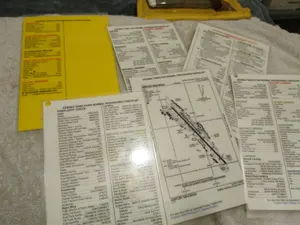

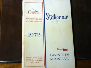

Parts listed for sale by vetted eBay sellers — confirmed on eBay at checkout.