CIRRUS SR22T Service Bulletin SB 2X-71-17
Cirrus SR22T · Service Bulletins
Overview
This document is a Service Bulletin for the Cirrus SR22T aircraft, specifically addressing the replacement of air box seals due to a potential disbonding issue. It outlines mandatory compliance requirements, instructions for the replacement process, and warranty information.
- Service Bulletin SB 2X-71-17 is mandatory for specific SR22T serials.
- Compliance must be completed within the next 10 flight hours.
- FAA approval has been obtained for the technical data in this bulletin.
- The bulletin provides instructions for replacing air box seals.
- Cirrus Design covers parts and labor for warranty aircraft if completed on time.
- The task requires approximately 2.25 manhours.
- Specific tools and parts are needed for compliance.
- FOD prevention is emphasized during installation.
Summary written by AI from the source document. Check the original before relying on it. See which parts of Sprinkle are written by AI.
Reference only, not for flight. Use the current approved manual for your aircraft. See terms, section 5.
Document
Source
Copy found at regulations.gov. Sprinkle hosts a reference copy with an added summary, specifications and searchable full text.
Document details
- Type ·
- Service Bulletins
- Year ·
- 2011
- File size ·
- 356 KB
- Copy found at ·
- regulations.gov
- Language ·
- en
What is the CIRRUS SR22T Service Bulletin SB 2X-71-17?
The CIRRUS SR22T Service Bulletin SB 2X-71-17 is a service bulletins for the Cirrus SR22T, dated 2011.
What year was the CIRRUS SR22T Service Bulletin SB 2X-71-17 published?
The CIRRUS SR22T Service Bulletin SB 2X-71-17 — the Cirrus SR22T service bulletins on file — is dated 2011.
Common. More common than 99% of the aircraft models we track.
Most owners only have the POH. Here's the essential set for the Cirrus SR22T.
- Pilot's Operating Handbook / AFM
- Checklist
- Maintenance Manual
- Parts Catalog (IPC)
- Systems & Wiring
- Service Bulletins on file
- Type Certificate (TCDS)
Cirrus SR22T for sale now
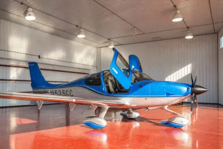
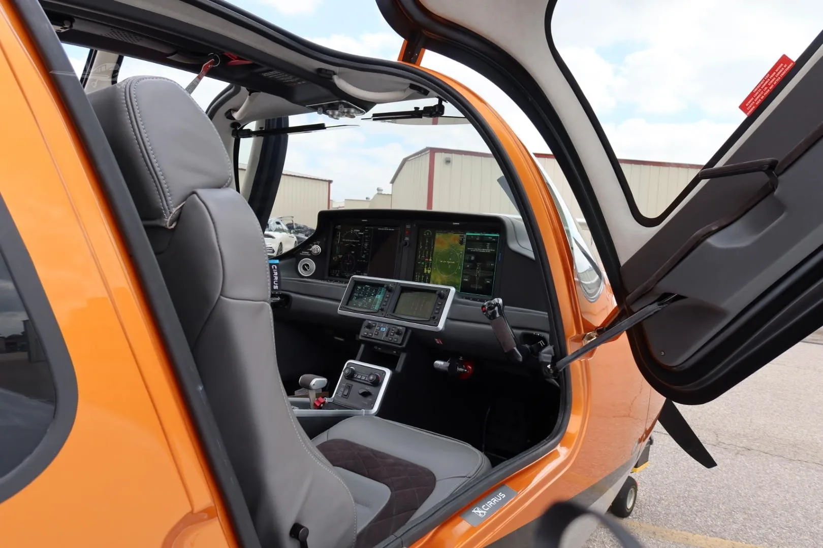
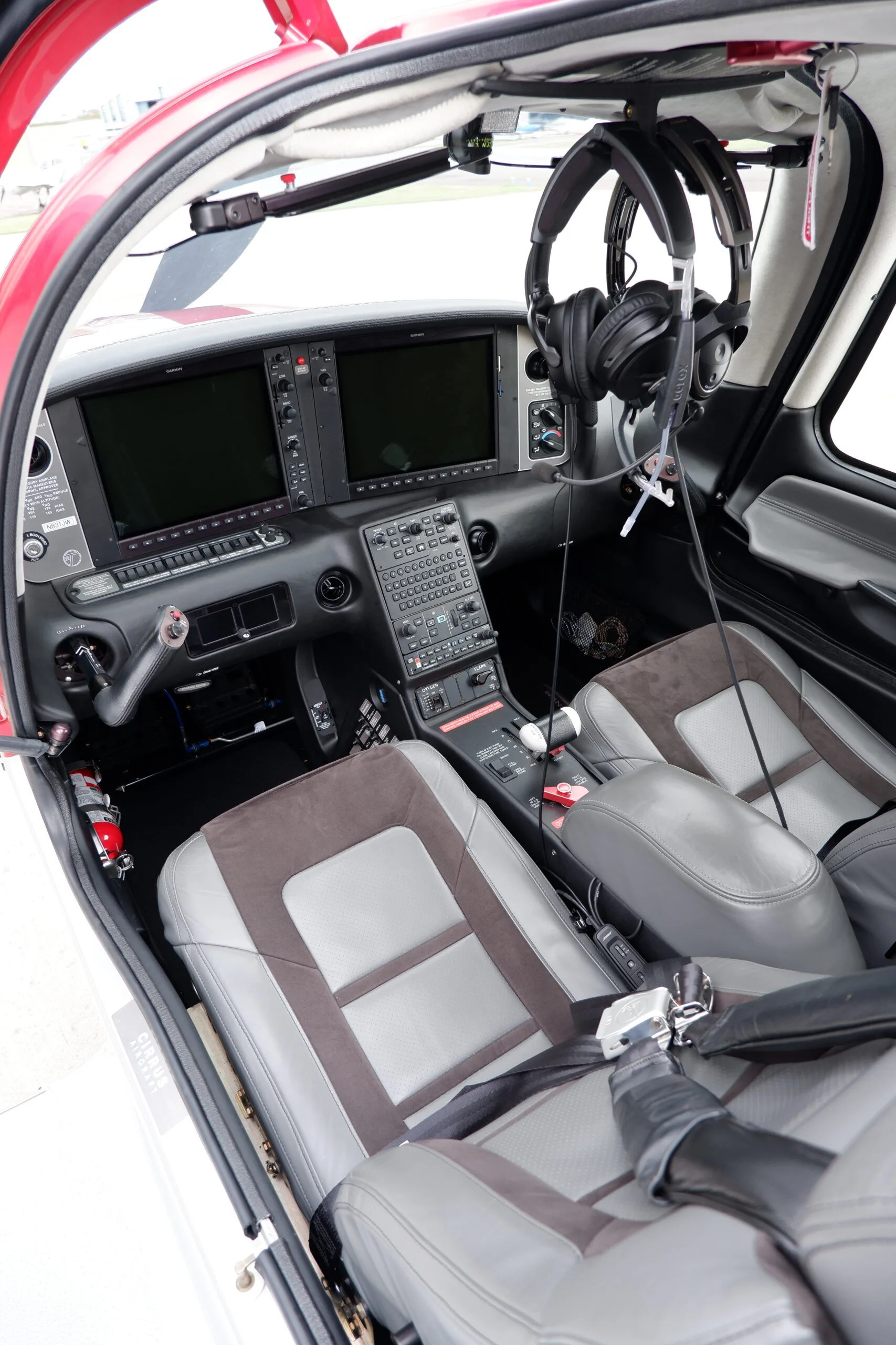
Free — save the SR22T to your watchlist and track it in one place.
More Cirrus SR22Tmanuals & documents
See all 18 →- Cirrus SR22T Model GuideModel Guide
- Vantage 12 Pilot’s GuideSystems Description
- Airworthiness Concern SheetAirworthiness Directives
- SERVICE BULLETIN HC-SB-30-390 Propeller - Spinner/Anti-ice Travel Tube InterferenceService Bulletins
- INSTRUCTIONS FOR INSTALLATION OF HARTZELL 4C1-F650A1/76C04(B)-0.6 PROPELLER ON CIRRUS SR22 AIRCRAFTMaintenance Manual
- INSTRUCTIONS FOR CONTINUED AIRWORTHINESS FOR HARTZELL 4C1-F650A1/76C04(B)-0.6 PROPELLER ON CIRRUS SR22T AIRCRAFTMaintenance Manual
- Supplemental Type Certificate SA03962ATSupplemental Type Certificate
- FLIGHT OPERATIONS MANUAL CIRRUS PERSPECTIVE AVIONICS - PILOT EDITIONPilot's Operating Handbook
- Continued Airworthiness Manual For Cirrus Design SR22 Series AirplanesMaintenance Manual
- Hartzell Engine Technologies Service Bulletin 033Service Bulletins
- SCHEDULE OF AIRWORTHINESS DIRECTIVESAirworthiness Directives
- SCHEDULE OF AIRWORTHINESS DIRECTIVESAirworthiness Directives
Related documents
- Cirrus SR2X Service Bulletin SB2X-33-07R1Cirrus SR22T G6 · Maintenance Manual
- Service Bulletin - AWSCirrus SR22 · Service Bulletins
- Service Bulletin - AWSCirrus SR20 G2 · Service Bulletins
- SERVICE BULLETIN M20-345AMooney M20C Ranger · Service Bulletins
- Service Bulletin TAT SB08-01Cirrus SR22 · Service Bulletins
If you fly the Cirrus SR22T, you may also be researching these.


In this document
Compliance
This Service Bulletin is mandatory and must be accomplished within the next 10 flight hours.
Effectivity
Applicable to SR22T serials 0001-0169, excluding specific serials listed.
Purpose
Addresses a condition where air box seals may disbond and be ingested into the turbocharger.
Description
Provides instructions for the replacement of the air box seals.
Warranty Information
Cirrus Design will cover parts and labor for warranty aircraft if work is done within the compliance period.
Accomplishment Instructions
Detailed steps for replacing the air box seals, including necessary tools and parts.
Summary written by AI from the source document. Check the original before relying on it. See which parts of Sprinkle are written by AI.
Safety notes
- Do not extend slots into any weld during the modification process.
- If airbox fit is loose, adjustments must be made to avoid fit-up problems.
- Ensure FOD cannot enter the induction system during installation.
Summary written by AI from the source document. Check the original before relying on it. See which parts of Sprinkle are written by AI.
Full document text
C I R R U S SR22T Service Bulletin SB 2X-71-17 Page 1 SR22T Serials 0001-0169, except 0019, 0027, 0047, 0097, 0126, 0127, 0135, 0138, 0139, 0144, 0154, 0155, 0157-0161, 0163. EFFECTIVITY: SB 2X-71-17 Number: 1. COMPLIANCE Mandatory: Cirrus Design considers this Service Bulletin to be MANDATORY. Accomplish this Service Bulletin within the next 10 Flight Hours. Compliance time begins upon receipt of this Service Bulletin. 2. EFFECTIVITY SR22T Serials 0001-0169, except 0004, 0019, 0027, 0047, 0097, 0126, 0127, 0135, 0138, 0139, 0144, 0154, 0155, 0157-0161, 0163. 3. APPROVAL FAA approval has been obtained on all technical data in this Service Bulletin that affects type design. 4. PURPOSE A condition can occur in which the induction system air box seal(s) could become disbonded and ingested into the turbocharger compressor. 5. DESCRIPTION This Service Bulletin provides instructions for the replacement of the air box seals. 6. WARRANTY INFORMATION For aircraft under warranty at the issue date of this Service Bulletin, Cirrus Design will cover all parts and labor costs for this Service Bulletin if the work is accomplished within the Compliance time period and the work is performed at an authorized Cirrus Design Service Center. 7. MANPOWER REQUIREMENTS 2.25 manhours. 8. OTHER PUBLICATIONS AFFECTED SR22/22T Airplane Maintenance Manual (p/n 13773-001) SR22/22T Illustrated Parts Catalog (p/n 13744-001) 9. WEIGHT AND BALANCE N/A SNS SUBJECT: 71-60 AIR INTAKES - Disbonding Of Induction System Air Box Seal(s) July 21, 2011 Issued: C I R R U S S E R V I C E B U L L E T I N M O D E L S R 2 2 T SB 2X-71-17 Page 2 SR22T Serials 0001-0169, except 0019, 0027, 0047, 0097, 0126, 0127, 0135, 0138, 0139, 0144, 0154, 0155, 0157-0161, 0163. EFFECTIVITY: July 21, 2011 10. MATERIAL INFORMATION The following parts are required to comply with this Service Bulletin. Parts can be obtained from an Autho- rized Cirrus Design Service Center or Parts Distributor. Order kit 70257-001 to obtain the following parts. 11. ACCOMPLISHMENT INSTRUCTIONS A. Acquire necessary tools, equipment, and supplies. B. Remove engine cowling. (Refer to AMM 71-10) C. Remove clamp securing air box to turbocharger. D. Disconnect air box from turbocharger. E. Remove and discard black rubber seal from air box. F. Remove residual adhesive from air box. G. Using Grinding Wheel, grind weld on outside diameter of airbox fitting flush to surrounding surface. (See Figure 1) CAUTION: Do not extend slots into any weld. H. Affected Serials in Range 0001 thru 0151, LH Air Box Only; Using Cut-Off Tool, extend three of the four air box flange slots to 0.90 inch (2.29 cm) with full radius on the end. Do not extend the top slot nearest to the weld. I. Affected Serials in Range 0001 thru 0151, LH Air Box Only; Using Cut-Off Tool, increase width of all four air box flange slots to 0.13 inch (3.30 mm). J. Affected Serials in Range 0152 thru 0169, LH Air Box Only; Using Cut-Off Tool, extend all four air box flange slots to 0.90 inch (2.29 cm) with full radius on the end. K. All Affected Serials, RH Air Box Only; Using Cut-Off Tool, increase width of all four air box flange slots to 0.13 inch (3.30 mm). Item No. Description P/N or Spec. Supplier Quantity 1 Reinforced Silicone Fiberglass Seal 29486-001 Cirrus Design 2 Description P/N or Spec. Supplier Purpose Grinding Wheel NA Any Source Abrading Cut-Off Tool NA Any Source Cutting Alodine Pen N/A Any Source Corrosion Prevention Emery Cloth 120 Grit Any Source Abrading Isopropyl Alcohol NA Any Source Solvent Cleaning RTV Prime Coat PR1204 Dow Corning Adhesive Primer RTV Sealant 736 Dow Corning Adhesive C I R R U S S E R V I C E B U L L E T I N M O D E L S R 2 2 T SB 2X-71-17 Page 3 SR22T Serials 0001-0169, except 0019, 0027, 0047, 0097, 0126, 0127, 0135, 0138, 0139, 0144, 0154, 0155, 0157-0161, 0163. EFFECTIVITY: July 21, 2011 L. All Affected Serials, RH Air Box Only: Using Cut-Off Tool, extend three of the four air box flange slots to 0.90 inch (2.29 cm) with full radius on the end. Do not extend the top slot nearest to the weld. M. Touch-up reworked areas with alodine pen. N. Abrade inside of Reinforced Silicone Fiberglass Seal with emery cloth and solvent clean with isopropyl alcohol. O. Abrade induction mounting flange on turbocharger with emery cloth and solvent clean with isopropyl alcohol. P. Clean air box of any residual machining debris. Q. Apply PR1204 RTV prime coat to turbocharger induction mounting flange. Cure for 2 hours. R. Apply a thin coating of 736 RTV sealant turbocharger induction mounting flange. S. Install Reinforced Silicone Fiberglass Seal to mounting flange pushing seal as far aft as possible. Remove excess RTV. Cure for 24 hours. CAUTION: Upon installation, If airbox fit is loose, remove from turbocharger, and use clamp to slightly reduce flange diameter. Use care not to over-compress and cause fit-up prob- lems. T. Install air box over turbocharger induction mounting flange. Torque clamp to 90-100 in-lb (10-11 Nm). U. Ensure FOD cannot enter induction system by inspecting air box flange and verifying fiberglass seal completely blocks air box slots. (See Figure 1) V. Install clamp securing air box to turbocharger. W. Repeat procedure on opposite turbocharger. X. Install engine cowling. (Refer to AMM 71-10) Y. Complete airplane records by noting compliance with SB 2X-71-17 in Aircraft Logbook. C I R R U S S E R V I C E B U L L E T I N M O D E L S R 2 2 T SB 2X-71-17 Page 4 SR22T Serials 0001-0169, except 0019, 0027, 0047, 0097, 0126, 0127, 0135, 0138, 0139, 0144, 0154, 0155, 0157-0161, 0163. EFFECTIVITY: July 21, 2011 Figure 1 Air Box Seal Installation 0.90 inch (2.29 cm) DO NOT LENGTHEN UPPER LOCATION 0.90 inch (2.29 cm) 0.13 inch (3.30 mm) LH side: Serials 22T-0001 thru 22T-0151. RH side: Serials 22T-0001 thru 22T-0169. LH side: Serials 22T-0152 thru 22T-0169. SLOT MODIFICATION AIR BOX (REF) CLAMP (REF) SEAL (REF)
Show full textShow less
SR2_SB71_1427 TURBOCHARGER (REF) Grind indicated weld on outside diameter of airbox fitting flush. Ensure FOD cannot enter induction system by inspecting air box flange and verifying fiberglass seal completely blocks air box slots. NOTE 3 PLC'S 4 PLC'S 4 PLC'S C I R R U S SR22T Service Bulletin Use this form to submit a Publications Change Request to our Engineering Department and/or to tell us what you think of the quality of this publication. We will use the data you provide us to improve the quality of our tech- nical publications. SB 2X-71-17 Number: Service Loop Evaluation Form Contact Information: Organization: _________________________________ Today’s Date: __________________________ Address: ____________________________________ Telephone No.: _________________________ City/ST/Zip: __________________________________ Fax No: _______________________________ Prepared By: _________________________________ E-Mail: _______________________________ Title:________________________________________ Location of Publication Change Request: Chapter Number: Section Number: Figure No (IPC or WM only): ___________________ Page Number: Page Date: Illustration Number (if applicable): _______________ Please consider the following suggestions for change: - - - - - - - - - - - - - - - - - - - - - - - - - - - - - - - - - - - - - - - - - - - - - - - - - - - - - - - - - - - - - - - - - - - - - - - - - - - - - - - - - - - - - - - - - - - - - - - - - - - - - - - - - - - - - - - - - - - - - - - - - - - - - - - - - - - - - - - - - - - - - - - - - - - - - - - - - - - - - - - - - - - - - - - - - - - - - - - - - - - - - - - - - - - - - - - - - - - - - - - - - - - - - - - - - - - - - - - - - - - - - - - - - - - - - - - - - - - - - - - - - - - - - - - - - - - - - - - - - - - - - - - - - - - - - - - - - - - - - - - - - - - - - - - - - - - - - - - - - - - - - - - - - - - - - - - - - - - - - - - - - - - - - - - - - - - - - - - - - - - - - - - - - - - - - - - - - - - - - - - - - - - - - - - - - - - - - - - - - - - - - - - - - - - - - - - - - - - - - - - - - - - - - - - - - - - - - - - - - - - - - - - - - - - - - - - - - - - - - - - - - - - - - - - - - - - - - - - - - - - - - - - - - - - - - - - - - - - - - - - - - - - - - - - - - - - - - - - - - - - - - - - - - - - - - - - - - - - - - - - - - - - - - - - - - - - - - - - - - - - - - - - - - - - - - - - - - - - - - - - - - - - - - - - - - - - - - - - - - - - - - - - - - - - - - - - - - - - - - - - - - - - - - - - - - - - - - - - - - - - - - - - - - - - - - - - - - - - - - - - - - - - - - - - - - - - - - - - - - - - - - - - - - - - - - - - - - - - - - - - - - - - - - - - - - - - - - - - - - - - - - - - - - - - - - - - - - - - - - - - - - - - - - - - - - - - - - - - - - - - - - - - - - - - - - - - - - - - - Evaluation: Please rate the quality of this publication. (good) 4 3 2 1 (poor) Please rate the quality of the illustrations. (good) 4 3 2 1 (poor) Is this publication easy to understand? (good) 4 3 2 1 (poor) Is this publication easy to use? (good) 4 3 2 1 (poor) Are the Material and Accomplishment Instructions accurate? (good) 4 3 2 1 (poor) Is the Manpower estimate accurate? (good) 4 3 2 1 (poor) Give the completed evaluation form to your Cirrus Field Service Representative or send this form to Cirrus Design Corporation: Manager - Technical Publications 4515 Taylor Circle Duluth, MN 55811 SNS SUBJECT: 71-60 AIR INTAKES - Disbonding Of Induction System Air Box Seal(s) July 21, 2011 Issued: Cirrus Design Corp 4515 Taylor Circle Duluth, MN 55811-1548 STAMP CIRRUS DESIGN CORPORATION 4515 TAYLOR CIRCLE DULUTH, MN 55811-1548