GENERAL AVIATION INSPECTION AIDS SUPPLEMENT NO. 1
Mooney M20F Executive · Service Bulletins
Overview
This document is a supplement to the General Aviation Inspection Aids, specifically addressing issues related to various aircraft models, including the Mooney M20F. It provides critical information on reported defects and malfunctions that have been identified in the field but may not have been fully evaluated at the time of publication. The aim is to inform operators and maintenance personnel about potential safety issues and corrective actions. The document includes inspection recommendations and service bulletins relevant to the Mooney M20F, ensuring that operators are aware of necessary maintenance practices to enhance safety and reliability.
- The elevator trim tab control tube on the Mooney M20F can wear significantly, leading to potential control issues.
- Service Bulletin No. M20-185 outlines inspection procedures for the elevator trim tab control tube.
- Operators should regularly check the condition of the trim tab control tube to ensure safe operation.
Document
Source
Originally published by rosap.ntl.bts.gov. Sprinkle hosts a reference copy with an added summary, specifications and searchable full text.
Document details
- Type
- Service Bulletins
- Year
- 1976
- Pages
- 80
- File size
- 3.0 MB
- Publisher
- rosap.ntl.bts.gov
Common. Rarer than 12% of the aircraft models we track.
Most owners only have the POH. Here's the essential set for the Mooney M20F Executive.
- Pilot's Operating Handbook / AFM
- Checklist
- Maintenance Manual
- Parts Catalog (IPC)
- Systems & Wiring
- Service Bulletins
- Type Certificate (TCDS)
Free — save the MOONEY M20F Executive to your watchlist and track it in one place.
More Mooney M20F Executivemanuals & documents
- Monticello Flying Club Pilot Transition Manual: Mooney M20FService Manual
- AAIB Bulletin: 9/2016Other Documents
- Airworthiness Directives; Hartzell Propeller, Inc. Compact Series PropellersAirworthiness Directives
- Material Approved for Incorporation by ReferenceService Bulletins
- SERVICE BULLETIN M20-248Performance Data
- Mooney M20F Executive Pilot's Operating HandbookPilot's Operating Handbook
- APPLICATION SHEETParts Catalog
- Service ManualService Manual
- Pilot's Operating Handbook for the Mooney M20F ExecutivePilot's Operating Handbook
- Emergency Procedures for the Mooney M20F ExecutiveEmergency Procedures
- Weight & Balance for the Mooney M20F ExecutiveWeight And Balance
If you fly the Mooney M20F Executive, you may also be researching these.
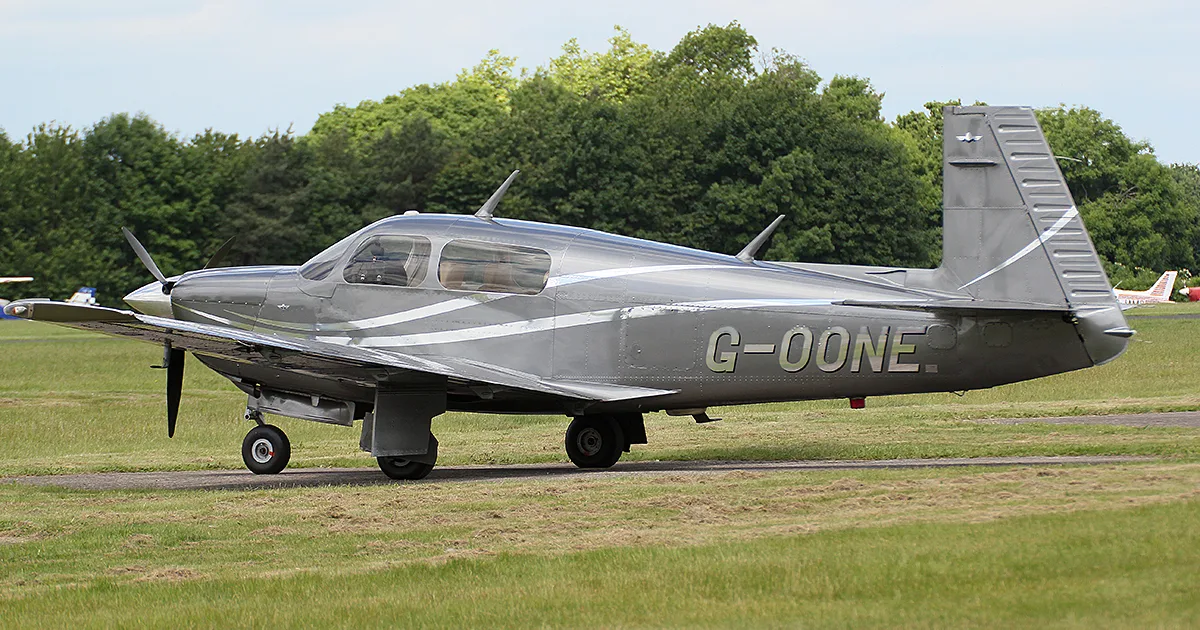




In this document
Mooney Model M20F Elevator Trim Tab Control Tube
The elevator trim tab control tube (P/N 915026-9) on the Mooney M20F has been reported to be severely worn at both ends where it rubs against the guide blocks. This wear can lead to malfunctioning of the elevator trim system. Mooney Service Bulletin No. M20-185 provides detailed inspection procedures and describes a protective kit designed to prevent further wear.
Safety notes
- Inspect the elevator trim tab control tube regularly to prevent wear-related failures.
Full document text
AC NO. 20-7N GENERAL AVIATION i n s p e c t i o n SUPPLEMENT NO. 1 SEPTEMBER 1976 U. S . D E P A R T M E N T O F T R A N S P O R T A T I O N FEDERAL AVIATION ADMINISTRATION Flight Standards Service GENERAL AVIATION INSPECTION AIDS C U M U L A T I V E I N D E X SEPTEMBER pp. 1-14 OCTOBER NOVEMBER DECEMBER FEBRUARY MARCH APRIL MAV JUNE BEECH 1-3 BELLANCA 3 BOEING 3 CESSNA 3-4 CURT1SS-WRIGHT 4 FAIRCHILD INDUSTRIES . . . . 5 MARTIN 5 MOONEY 5 PIPER 6-8 RAVEN 9 ROCKWELL INTERNATIONAL . . 9 SMITH 9 SWEARINGEN 9 A I R C R A F T BENDDC 10 TITAN 10 A C C E S S O R I E S C O M M U N I C A T I O N / N A V I G A T I O N E Q U I P M E N T DORNE AND MARGOLIN . . . . 10 COMMUNICATION COMPONENTS CORPORATION 11 NARCO 11 CONTINENTAL 11 LYCOMING 12-13 UNITED AIRCRAFT OF CANADA . 13 E Q U I P M E N T E N G I N E S M A I N T E N A N C E N O T E S AIRCRAFT WIRING HARNESS SPIRAL WRAPPING 13 CARBURETOR CLEANING 14 CONTINENTAL AND LYCOMING ENGINES USING CRANKSHAFT DAMPERS 14 CORROSION 14 ADVISORY CIRCULAR AC 20-7N CH 1 U.S. DEPARTMENT OF TRANSPORTATION FEDERAL AVIATION ADMINISTRATION WASHINGTON, D.C. 20590 GENERAL AVIATION INSPECTION AIDS SUPPLEMENT No. 1 SEPTEMBER 1976 This is the home of the General Aviation Inspection Aids. The publication is prepared from information submitted by those of you who operate and maintain civil aeronautical products. The content of this publication includes select ttems that have been reported to be significant but were not fully evaluated by the time the material went to press. As additional facts, such as cause and corrective action, are identified, the data will be brought to your attention in subsequent issues of the Aids. This action has been imple mented to give Aids' readers the earliest notice of reported conditions received via Malfunction or Defect Report, FAA 8330-2. Computers will constantly monitor these conditions during the period of evaluation for cause a n d corrective action. Your comments a n d suggestions for improvementare alwayswelcome. If you wish to share in such mate rial, please B e n d to: FAA, Flight Standards Technical Division, Attn: AAC-236, P.O. Box 25082, Oklahoma City, Oklahoma 73125. A I R C R A F T BEECH BEECH MODEL 33, 35, 36, 55 AND 58 SERIES AIRCRAFT--OIL FILTER ADAPTERS AND NEW TYPE OIL FILTERS Teledyne Continental Motors recently made a change to the oil filter adapter used with the 0-520 series engines. The by-pass valve in the adapter was removed and is now incorporated in the new type "gold" oil filters (P/N's 641583 and 641584). With this change a situation can occur which we feel should be brought to the attention of owners/ operators and maintenance personnel. If the old type "black" oil filters (P/N's 632399 and 637584) are used with the new oil filter adapter, P/N 641639, there will not be a by-pass in either unit and proper oil pressure cannot be obtained with cold oil. However, oil pressure will be normal after the oil warms up. Teledyne Continental Motors Service Bulletin No. M75-27 dated November 1975 pertains to this subject. It Is suggested this service bulletin be consulted for additional information. Beech aircraft affected: Models F33A, S/N's CE-572 and on; F33C, S/N's CJ-86 and on; V35B, S/N's D-9757 and on; A36, S/N's E-670 and on; E55, S/N's TE-1044 and on; 58, S/N's TH-615 and on; and 58P, S/N's TJ-4 and on. SA FETY I s A v i a t i o n ' s G r e a t e s t A s s e t GENERAL AVIATION INSPECTION AIDS 1 Beech Oil Pressure Cracks are reported to have occurred in the oil pressure gauge Model 35 Series Gauge Line line of these aircraft, resulting in loss of engine oil and sub sequent emergency landings. In these instances the lines were made of copper. Copper tubing should be inspected for cracks, hardness, brittleness, and general condition at regular intervals. Copper becomes hard and brittle from vibration; however, it may be restored to the soft annealed state by heating to a red-hot con dition and quenching in cold water. This annealing process should be accomplished if the copper tubing is removed for any reason. The copper tubing may also be replaced with aluminum alloy or corrosion-resistant steel tubing. BEECH MODELS C35 THROUGH H35 AIRCRAFT—FUEL SELECTOR VALVE HANDLE Reports have been received which indicate that the fuel selector valve will sometimes stick due to lack of usage. Other reports cite a misunderstanding as to which end of the fuel selector valve handle serves as the tank selection pointer. In this regard, the shorter, narrow thin end of the old type handle (P/N 35-924251) is to be pointed toward the desired fuel tank. Beech Class II Service Instructions No. 0670-289 and Beechcraft Executive Airplane Safety Communique No. 35-28 were both released in late 1974. Each publication refers to the availability of a newly designed handle for the fuel selector valve. The new handle, which is identified by P/N 35-924287-1, features a better hand grip area and improved visual pointer capability. This handle replaces the handles on the P/N 35-924230 fuel pump or the handle which was included in Kit No. 35-576S. In addition, the Safety Communique contains a preflight procedure the pilot can use to assure the fuel selector valve Is not binding and that the selector indicator is positioned to the desired fuel tank prior to takeoff. Airplanes affected: S/N's D-2901 thru D-5330, except D-5062. Beech Emergency Hand Crank -- There have been a few reports of spar covers installed so the Models V35B, 95-B55, Main Landing Gear landing gear emergency handle is covered and cannot be used, and 58P Investigation of these reports disclosed that the spar covers were installed after alterations in the field without any con sideration given to the functioning of the emergency hand crank. It is recommended that the emergency landing gear hand crank be checked for clearance from obstructions prior to being re turned to service after maintenance or servicing has been accomplished in the cabin area.
Show full textShow less
Beech Engine Mount Numerous reports of cracks found in the tubular engine mounts Models 95, B95, B95A, of these aircraft have been received. Beech recommends the D95A, and E95 engine mounts be Inspected with at least a four-power magnify ing glass every 100 hours time in service. This inspection is specified in Beech Class II Service Instructions No. 0816- 241. These engine mounts are not heat treated; therefore, if cracks are found during this inspection, repairs can be made using the guidelines contained in the welding section of FAA Advis ory Circular No. 43.13-1A. DON'T PUT IT OFF ANY LONGER - If you have recently experienced mechanical difficulties or problems with an aeronautical product and have not reported it yet, please do so now and help your fellow airmen. FAA Form 8330-2, available from your local General Aviation District Office, may be used for this purpose. The form requires no postage and is preaddressed to receive prompt handling. 2 GENERAL AVIATION INSPECTION AIDS BEECH MODEL 90, 99, 100 and 200 SERIES AIRCRAFT -- ENGINE FUEL DRAIN COLLECTOR SYSTEM Inoperative or defective float switches in the engine fuel drain collector tanks will allow fuel from the tanks to over flow onto the ramp. Beech has issued Class I Service Instructions No. 0763-282 which announces the availability of an improved float switch. It is suggested that this service instruction be complied with if problems are encountered with the existing float switches. BELLANCA Bellanca Model 14-13-2 Wing Spar At 1555 hours aircraft time in service, external examination of the wing surfaces failed to reveal any evidence of wood decay. Removal of the plywood skin from suspected areas revealed extensive wood deterioration of the left wing rear spar adjacent to the upper attachment fitting and the right wing front spar 70 inches outboard of the upper attachment fitting. Bellanca Carry Through Spar, The rear spar carry through truss was found to be cracked Model 14-19-3 P/N 190202 during inspection. The vertical members were cracked adjacent to the welds at the upper rear spar attachment fittings. The left side was cracked approximately 90 degrees around the circumference and the right side was cracked approximately 40 degrees around the circumference. BOEING Boeing (Vertol) Rotor Hub Horizontal During inspection to determine the cause of an oil leak in the Model 107-n Hinge Pin Bearing. forward rotor hub, the horizontal hinge pin bearing liner was P/N A02R8262-1 found to be cracked. Total time in service - 2864 hours. The life limit specified by the manufacturer for this part is 4000 hours. CESSNA Cessna Model 310G Landing Gear Actuator Gearbox, P/N 0894000 The landing gear collapsed during landing roll. Investigation revealed that the gearbox sector gear had failed at the pivot shaft. Further checks disclosed that the landing gear was misrigged, and the sector gear was contacting the internal stop. The sector gear was dented at point of contact. GENERAL AVIATION INSPECTION AIDS 3 CESSNA MODEL 310, 320 AND 400 SERIES AIRCRAFT -- RUDDER PEDAL TORQUE TUBE ASSEMBLY Bending and breakage of the rudder pedal posts and control cable attach arms welded to the rudder pedal torque tubes continue to be reported. Airplanes manufactured prior to March 1970, are particularly susceptible to this type prob lem. Affected part numbers are: Models 310 and 320 -- P/N's 0813018-1 and -2; 0861700-1 and -2. Model 400 Series — P/N's 5015006-7, -8 and -9; 5115260-1 and -4. It is recommended these torque tubes be carefully examined for deformation or cracks in the welded areas during regularly scheduled inspections. Removal of the cabin floorboards is necessary to properly accomplish this in spection. Cessna Service Letter No. ME71-1 announced that a strengthened torque tube had been developed for inclusion in pro duction 400 series aircraft and for use as spares. This service letter also provided instructions for the modification of existing torque tubes. In March 1970, a reinforcing sleeve was added to the torque tubes used on Model 310 pro duction aircraft and spares. A modification similar to that described in Service Letter ME71-1 can also be added to the torque tubes originally installed in early Model 310 and 320 airplanes. CESSNA MODEL 310, 401, 402 and 411 SERIES AIRCRAFT — EMERGENCY EXIT WINDOW RELEASE HANDLE A number of instances have been reported where the handle on the emergency exit was pulled, probably out of curious- ity, and then stowed so the condition was undetectable by visual inspection. On a subsequent flight, the emergency exit window blew off unexpectedly. When the emergency exit handle is pulled on these airplanes, the retaining pins are withdrawn from the window frame. Merely returning the handle to its normal position will not reinstall the pins to their locked position. An acceptable method to prevent occurrences such as these is to tag the exit release handle for easy preflight in spection. Use a fine wire such as a 5-amp fuse wire or .011 copper safety wire and secure it loosely between the handle and the window trim. If the handle is displaced enough to disengage the retaining pins, the wire will be broken, thereby indicating an unsafe condition during the next preflight. Cessna Elevator Torque Model 401, 402, 411, Tube Fittings 414 and 421 Series There have been several reports of cracks found in the \#~\ TYPICAL CRACKS torque tube fittings, especially at the taper pinholes. Cracking at these holes is believed to be caused by m """ ' ~^^Q$Jp*~^ /~»SSS&'^S'Ma "'" overtorquing the taper pins. The recommended torque &_3§L ^ S S ^ O T W R I K J D > value for these pins is 50 - 10 inch-pounds. It is suggested that these fittings be checked for cracks " #e<«!&%8 and corrosion at each annual or 100-hour inspection, or whenever the tail cone is removed for any reason. Cessna Service Letter No. ME71-8 provides additional information on this subject. CURTISS-WRIGHT Curtiss-Wright Elevator Bellcrank, Elevator control was lost during takeoff. Investigation re- Model C-46F P/N 2053030441 vealed the lower end of the elevator bellcrank had failed adja cent to the torque tube attachment bearing. S A F E T Y i s the responsibility of everyone in Aviation. 4 GENERAL AVIATION INSPECTION AIDS FAIRCHILD INDUSTRIES Fairchild Industries Cyclic Input Ring Assembly, A cyclic input ring assembly failure is believed to have been Model FH-1100 P/N 24-34205 caused by use of incorrect torque when installing the vertical assembly bolts. A torque value, significantly lower than specified by the manufacturer, was used which caused improper distribution of longitudinal cyclic control loads and subsequent failure of the ring assembly. The importance of using the correct torque values when assembling rotorcraft components cannot be over-emphasized. MARTIN Martin Nose Landing Gear An unsafe nose landing gear indication resulted because the Model 404 Downlock, P/N 202SD82043 downlock plunger had only extended half of its full travel. Flaking of the metal plating on the lock plunger pin caused it to bind, preventing full extension Martin Horizontal Stabilizer Spar During inspection, corrosion was found on the front spars of Model 404 both the right and left horizontal stabilizers. The corrosion was located on the upper spar caps approximately 20 inches outboard of the aircraft centerline. MOONEY Mooney Model M20F Elevator Trim Tab Control Tube, P/N 915026-9 The elevator trim tab control tube was found to be severely worn at both ends where it rubs on the guide blocks. Mooney Service Bulletin No. M20-185 provides informa tion for inspection in this area and describes a kit which protects the trim tube from wear. 915026-9 210118-13 Tube Guiije Block 210084-9 Searing Block F L O O R B O A R D R E F . B E L L Y F A I R I N G F O R M E R , S T A . 9 0 . 7 5 , R E F . GENERAL AVIATION INSPECTION AIDS 5 P I P E R Piper Fuselage Longeron Cracks have been detected in the upper fuselage longerons Model PA-18 adjacent to the aft horizontal stabilizer support assembly, P/N 21161-00, welds. Bending loads imposed upon the longerons due to binding of the pivot tube, P/N 86062-79, in the support assembly during trim actuation, is a possible cause factor. Frequent lubrication of the pivot tube and support assembly is recommended. Piper Elevator Cable Elevator control was lost immediately following takeoff, Model PA-18S Turnbuckle Terminal requiring the pilot to execute a straight-in emergency landing maintaining altitude control by use of the throttle. Investiga tion revealed the upper elevator cable turnbuckle terminal had failed adjacent to its bellcrank attachment. The terminal fork to bellcrank attachment was rusted causing the terminal to bend rather than swivel during elevator control actuation, resulting in eventual failure. The aircraft had been operated 97 hours and 12 months since last inspection. Piper Wing Spar Piper Service Letter No. 591 issued August 31, 1971, called Models PA-23-235 for a one-time inspection of certain serial number aircraft and PA-23-250 wing front spars for cracks. The service letter identified the areas where cracks might be found and specified reinforce ment kits to be used in the event cracks were detected. A repeated examination during a recent 100-hour inspection of a PA-23-250 aircraft at 2500 hours time in service, revealed the front spars of both wings were cracked. Careful examina tion of the spar areas identified in service letter No, 591 is recommended each 100-hour or annual inspection. Piper Landing Gear Anti-Retraction Loss of hydraulic and CO- pressure due to failure of the sub- Model PA-23-250 Valve Hose, P/N 17766-27 ject hose assembly prevented the nose landing gear to lock in the down position. Deterioration of the hose due to exposure to the elements was the cause of failure. The hose had been in service for 2,315 hours and several years. Piper Landing Gear Retract Several attempts had to be made to obtain a landing gear Model PA-24-250 Coil Spring, P/N 83302-39 down and locked indication. Inspection revealed the cause of difficulty to be inadequate tension on the coil spring, P/N 83302-39, which attaches to the transmission motor brake arm assembly, P/N 23042-00. Inadequate spring tension was the result of loosening of the cotter pin which secures the upper end of the spring to the cockpit floor. Piper Stabilator Balance Testing by the manufacturer indicates cracks may develop Models PA-24-250 Weight Tube in stabilator balance weight tubes, P/N 28035-00, installed and PA-24-260 per Piper Service Letter No. 687 dated June 19, 1974. Sufficient radius was not provided at the balance weight cut out of the subject tubes. Piper Service Bulletin No. 493 dated June 4, 1976, calls for the installation of new P/N 28035-00, tubes within the next 100 hours of operation for certain serial number aircraft that have been modified per SL 687. The new tubes have a reshaped balance weight cut-out with radius cut corners to preclude corner cracks. 6 GENERAL AVIATION INSPECTION AIDS Piper Model PA-24-260 Rudder Hinge Bracket, P/N's 20707-02 and 20707-03 During a routine annual inspection at 1092 hours time in service, the rudder top hinge bracket, P/N 20707-02, and the center bracket, P/N 20707-03, were found to be cracked. The cracks originated at the outer race of the pressed-in bearing and had progressed to the edge of the brackets. Piper Model PA-28-140 Hose Assembly, P/N 61413-02 The oil cooler hose assembly failed, resulting in loss of oil and engine failure. Total time in service - 3327 hours. Piper Model PA-28-151 Hose Clamp, P/N 62858-02 The pilot reported that the elevator control jammed in flight. Investigation revealed that when the elevator control Is pulled back approximately 5-inches, the aileron chain will catch on the vacuum regulator hose clamp. If the clamp is installed with the adjustment worm down, the chain-to-clamp clearance is less than 1/8-inch. If the clamp adjustment worm is in stalled on top of the hose, the clearance increases to approx imately 3/8-inch. Piper Model PA-31 Main Landing Gear Uplock Rod, P/N 41949-03 After takeoff, the landing gear would not lock in the up posi tion. During landing roll-out, the right main gear collapsed. The cause was traced to binding of the main gear uplock rod. Due to a number of similar reports, Piper issued Service Letter No. 755, which calls for inspection and lubrication of landing gear actuator rods each 100-hour, annual or pro grammed inspection. Piper Model PA-31 Aileron Interconnect Cable During a routine 100-hour inspection, the aileron interconnect cable was found to be chafing against the edge of a lightening hole under the cabin floor, just forward of the rear spar. Piper Model PA-31 Battery Box Drain Tube During a routine inspection, the battery box overboard drain line was found to be clogged and separated from the box. If this condition had not been detected, corrosion of the aircraft structure could have occurred. Piper Model PA-31 Series Flap Drive Transmission, Dukes P/N 4268-00 Several reports of worn flap drive transmission ball shafts have been received. The wear has been detected on the machined surface on the end of the shaft which enters the bearing immediately forward of gear, P/N 2154-53, and the threaded portion of the shaft. This condition has been found when complying with AD 76-10-06 and installing transmission gear overhaul kit, Piper P/N 761 059. Piper Model PA-31-350 Nose Landing Gear and Torque Link When replacing the nose landing gear strut upper housing assembly, P/N 40273-00, which was damaged due to improper ground handling, additional discrepancies were noted. Both upper and lower torque link bolts were nearly sheared and their attachment points at the cylinder assembly and fork assembly were badly distorted. Complete disassembly was required to detect this hidden damage. The damage required replacement of both torque links, P/N 45318-00, both torque link bolts, P/N 402 344, cylinder assembly, P/N 45314-00, and fork assembly, P/N 45333-03, in addition to the upper strut housing, P/N 40273-00. GENERAL AVIATION INSPECTION AIDS 7 Piper Model PA-31-350 Elevator Balance Weight, P/N 53104-00 Several reports of loose and broken elevator balance weights have been received. In one instance at an aircraft total time of 389 hours, the left balance weight had broken and pieces had worked their way to the elevator trailing edge. This condi tion was detected when complying with Piper Service Bulletin No. 500. A similar condition was found during a routine pre- flight inspection, and the aircraft total time In service was 510 hours. Another report advised of a loose balance weight bolt found at 181 hours on an aircraft which had Service Bulletin No. 500 and modification kit No. 761 041 incorporated. Service Bulle tin No. 500, dated April 23, 1976, calls for installation of balance weight modification kits within the next 50 hours of operation. Piper Model PA-31P Landing Gear Control Handle Lockout Solenoid, P/N 487-155 A pilot inadvertently moved the landing gear control lever to retract position causing the nose landing gear to collapse during engine start. Investigation revealed the lockout pin in the subject solenoid was stuck In the retracted position defeat ing its purpose, permitting movement of the selector lever to retract position when the aircraft was on the ground. Piper Model PA-31T Elevator Hinge System Modification Recent testing of the aircraft structure by the manufacturer revealed a need to strengthen the elevator hinge system. Piper Service Bulletin No. 504, dated June 1, 1976, appli cable to aircraft starting with S/N 31T-7400001 through 31T-7620039, calls for installation of modification kit No. 761 056 at the next "Continuous Maintenance Event", not to exceed the next 50 hours of operation. The modification consists primarily of new elevator mating hinges, support and attach ment components, and hardware. Piper Model PA-31T Engine Mounts The Piper Continuous Inspection Program for the PA-31T aircraft, calls for replacement of engine top mounts, P/N's 761 603 and 761 604, each 400 hours of operation. Piper Service Letter No. 780, dated June 8, 1976, advises of new top mounts, P/N's 761 612 and 761 613, refined to offer in creased service life. The service letter states, replacement of the new part number mounts will not be required until scheduled engine removal as long as routine and detailed engine inspections ascertain continued serviceability. Piper Model PA-34-200 Nose Landing Gear System During approach for landing, the nose gear failed to extend. A gear-up landing was made. Inspection revealed the nose strut aligning ball end had missed the retract track assembly and Jammed the nose gear. Further inspection disclosed that the steering arm assembly, P/N 95395-00, secured to the mount assembly, P/N 95551-23, had deflected upward per mitting the ball to miss the track assembly, P/N 95759-07. Also, the boltholes in the mount assembly were elongated. Piper Model PA-36-285 Wing Spar Bolt Piper Aircraft Corporation advised exhaustive fatigue testing of the PA-36 wing structure has resulted in the establishment of a 2000-hour life limit for the subject bolts. Piper Service Bulletin No. 501 applicable to aircraft serial number 36-736001 and above, provides information for procuring bolt replacement Kit No. 761 058 and installation instructions. 8 GENERAL AVIATION INSPECTION AIDS RAVEN Raven (Balloon) Model AX 7 Inflater, P/N DPB2000 During balloon inflation with a hand-held inflater, the nozzle jet of the inflater came off. This permitted raw propane to escape and ignite. The pilot received burns and one panel in the skirt and one panel in the envelope were damaged. In vestigation revealed that the nozzle is silver soldered in place. This inflater is also used as installed equipment on Piccard balloons. ROCKWELL INTERNATIONAL Rockwell International Engine Mount, Model 500 P/N's 3620025-1 and -2 The upper mounts of both engines were found to be heavily corroded. Total time in service - 4138 hours. Rockwell International Vertical Stabilizer Pairing Model 685 The vertical stabilizer fairing failed at the ADF sense antenna attach point. Total time in service - 1300 hours. SMITH Smith Model 601A Fuel Selector Knob The right fuel selector valve knob came off while changing tanks. Investigation revealed that the setscrews retaining the knob on the shaft had worked loose. Further checks disclosed that the shaft had a flat side for one setscrew, but not the other. SWE ARINGEN Swearingen Model SA226-AT Elevator Quadrant, P/N 27-44046-5 The elevator quadrant was found cracked in the web adjacent to the main pivot point. The crack involves approximately 10 percent of the web area. SAFETY is the Responsibility of Everyone in Aviation. GENERAL AVIATION INSPECTION AIDS 9 A C C E S S O R I E S BENDIX Bendix Capacitor, The left magneto capacitor was found broken during an investi- Magneto P/N 10-382681 gation to determine why the engine would not start. Total Model D2200 time in service - 251 hours. Bendix Coil retainer screw, Magneto P/N 10-382649 Models D6LN-2021 and D6LN-2230 Disassembly of magnetos to determine the cause for malfunctioning revealed that the coil retaining screws had loosened and backed out. The screws were found inside the magneto case and had caused damage to rotating components including the distributor gears. BENDIX MAGNETO—DRIVE COUPLING Pieces of metal and rubber from a failed magneto drive coupling were found in the engine oil system. The magneto was replaced and the engine crankcase was cleaned and flushed. Approximately 200 hours later, the oil cooler ruptured causing complete loss of engine oil. Inspection revealed that the oil cooler was plugged with rubber and metal known to be from the previous magneto drive coupling failure. TITAN Titan Fuel Pump Model G-6 Mating Surface Screws The cause for inflight stoppage of the left engine installed in a Piper PA-31-325 aircraft was traced to severe external fuel leakage through the parting surface of the engine driven fuel pump. Inspection revealed although the mating surface screws were properly safetied, they all became loose during 240 hours of operation. This condition allowed much raw fuel to be pumped into the engine compartment adjacent to the turbocharger presenting a potential for an inflight fire or explosion. COM M U N I C A T I O N / N A V I G A T I O N E Q U I P M E N T DORNE AND MARGOLIN Dome and Margolin CDI Indications An operator of a fleet of Learjet aircraft has reported VOR Antenna unstable and erroneous VOR course deviation indicator Model DM-N4-15 readings during flight operation. Many times, the cause of difficulty has been traced to the subject antennas. Examina tion of the defective units revealed paint separation that follows the boot portion at the edge of the antenna. 10 GENERAL AVIATION INSPECTION AIDS E Q U I P M E N T COMMUNICATION COMPONENTS CORPORATION Communication Components Emergency Locator Transmitter Model CIR-10 Battery During a 100-hour inspection, the ELT mounting plate was found to be severely corroded. Also, the ELT was Inopera tive. Further checks disclosed that the ELT battery was leaking. NARCO NARCO Internal Corrosion Many reports of internal corrosion, lead separation, and Emergency Locator inoperative units have been received. These conditions have Transmitter been found during inspection performed several months prior Model ELT-10 to the placarded battery expiration date. E N G I N E S CONTINENTAL Continental Model IO-520-E Crankshaft, P/N 631716 An inspection to determine the source of an oil leak revealed that the crankshaft was cracked behind the propeller flange. The crack extended approximately 3/4 of the way around the shaft. NOTICE TO READERS: The General Aviation Inspection Aids are, for the most part, prepared from Information supplied by those who operate and maintain aircraft. The FAA encourages the reporting of all malfunctions or defects that come to the attention of service or operating personnel, even though the problem has been previously reported. FAA Form 6330-2, available from the local General Aviation District Office, may be used for reporting purposes. GENERAL AVIATION FNSPECTON AIDS 11 LYCOMING Lycoming Magneto Impulse Coupling A "thud" followed by engine stoppage was experienced during Model O-320-A2B flight. Investigation revealed that the left magneto impulse coupling had failed. A piece of the failed coupling was found to be lodged between the magneto driven gear and the drive gear which also drives the engine camshaft. Lycoming Connecting Rod, The engine was disassembled and inspected at 374 hours time Model O-360-A1A P/N LW 11750 in service because metal particles were found In the oil screen. Magnetic particle inspection revealed that the No. 3 cylinder connecting rod was cracked adjacent to a top bolt- hole. Records show a cylinder, piston, and spark plugs were replaced because of foreign object damage at 2 hours time in service, and the propeller was replaced at 274 hours time in service because of damage experienced during a gear-up landing. Lycoming Crankshaft Failure of the engine crankshaft resulted in complete loss of Model O-360-A3A the propeller and part of the engine nose section during flight. Records disclosed that 41 hours prior to the incident, the propeller was replaced due to blade damage incurred when the aircraft struck a snowbank during taxi. The engine had not been inspected internally although Lycoming Service Letter No. L163A advises, "In the case of sudden engine stoppage the safest procedure is to remove and disassemble the engine and inspect the reciprocating parts. " Lycoming Push Rod Tube When checking for exhaust valve guide wear per Service Model VO-435-AIF Bulletin No. 388 at 456 hours TSO, all intake and exhaust push rod tubes were found to be excessively worn. Investi gation revealed washers, P/N 71549, had been installed on the outboard side of the rocker shafts rather than the inboart side during engine overhaul. This caused misalignment of the push rods in their housings resulting in wear of the push rod tubes during engine operation. Lycoming Temperature Control Oil The engine was disassembled because of reported high oil Model TIO-540-J2BD Cooler Bypass Valve temperature. Inspection revealed the temperature control I cooler bypass valve seat was elongated. Also, the nut whi( retains the valve and spring to the bypass valve shaft was missing and found inside the oil cooler. The nut is safetiet >y crimping to conform to the flats on two sides of the threadt shaft. It appears this crimping action causes thread diser gagement between the nut and shaft perpendicular to the crimped areas. Lycoming Crankcase The engine crankcase was found to be cracked. The crack Model TIO-540-J2BD which was located at the base of the No. 6 cylinder below the top forward stud extending to the raised No. 6 on the crank case, was found when checking for the source of an oil leak. This area is obscured by the cylinder baffle and is not clearly visible without removing the cylinder. Total time in service - 1332 hours. 12 GENERAL AVIATION INSPECTION AIDS Lycoming Oil Filter Seal Avco Lycoming Division advises loss of engine oil and Model TIO and possible engine damage could result if oil seals supplied with TIGO-541-E Series other than Lycoming oil filter element kit LW-11198 are used. Other manufacturers' oil filter element kits listed in Service Letter No. L178 and Service Bulletin No. 397 are acceptable If used with O-ring seal, P/N's MS-9021-154 or MS-29513- 154, obtainable through any Avco Lycoming distributor. Service Bulletin No. 397 pertains to the subject and provides necessary installation Instructions. Lycoming Manifold Pressure Relief Valve Avco Lycoming has introduced as optional equipment a manl- Model TIGO-541-6 fold pressure relief valve to prevent inadvertent engine over- boost. This valve supplied with Kit, P/N 14383, limits manifold pressure to 47.75 inches HG which will help prevent exceeding engine horsepower limitations and overstress of engine parts, Lycoming Service Instruction No. 1337 pertains to the subject. UNITED AIRCRAFT OF CANADA United Aircraft Turbine Disc, An explosion type noise followed by fire from the right engine of Canada P/N 3013511 exhaust was experienced in flight. The propeller was Model PT6A-6 feathered and ground inspection revealed turbine blades and boltheads in the exhaust pipe. Engine teardown inspection disclosed the gas generator turbine disc had failed. United Aircraft Drive Shaft Bearing, The engine was shutdown in flight due to loss of oil pressure, of Canada P/N 3021467 Investigation revealed that the main input drive shaft bearing Model PT6T-3 had failed. United Aircraft Fuel Pump, Pesco, An in-flight engine flameout was found to have been caused by of Canada P/N V25277-300-02 worn splines on the drive coupling, P/N 02-14910-01, and fuel Model PT6T-3 pump shaft. M A I N T E N A N C E N O T E S AIRCRAFT WIRING HARNESS SPIRAL WRAPPING It was found during the investigation of a recent aircraft electrical fire that the polyethelene spiral wrapping used with the aircraft wiring harness continued to burn after the ignition source was removed causing substantial addi tional damage. Certain types of polyethelene spiral wrapping will not meet the FAR 23 flame resistance requirement or the FAR 25 flame self-extinguishing requirement. It is suggested that persons responsible for replacement or modifications to aircraft wiring consult their local General Aviation District Office if any doubt exists as to the acceptability of spiral wrap materials selected for use. Aviation SAFETY is everyone's responsibility. GENERAL AVIATION INSPECTION AIDS 13 CARBURETOR CLEANING Follow the cleaner manufacturer's Instructions. DO NOT expose non metal parts to carburetor cleaning solutions. Carburetor cleaning solutions are formulated to be used on metal only and can have a very adverse effect on non metal materials. Parts which are made with both metal and non metal-- such as floats, gaskets, accelerator pump plungers, etc., --must not be cleaned or rinsed with cleaners. If non metal parts have been accidentally exposed to cleaners, they must be scrapped. Non metal parts must not be steam cleaned. The photograph shows non metal parts which have been exposed to carburetor cleaner. Marvel-Schebler/Tillotson Service Bulletin No. Al-76 and Aircraft Carburetor Overhaul Procedures Manual relate to this subject. EXAMPLES OF DAMAGED HON METAL CARBURETOR PARTS WHICH HAVE LEITT EXPOSED TO CARBURETOR CLEANER CONTINENTAL AND LYCOMING ENGINES USING CRANKSHAFT DAMPERS Engine damper systems are precisely tuned centrifugal pendulum dynamic absorbers. Without these types of finely tuned devices, many highly efficient reciprocating aircraft engine-propeller combinations in service today would not be possible. Being so designed, it is necessary that this precise tuning be maintained in service or its effectiveness is lost. Unlike other wearing parts of the engine such as bearings, rings, cylinders, etc.; detectable by loss of oil pressure, high oil consumption, or cylinder compression checks, dampers have no such wear symptoms. Contrary to much popular belief, wear of these assemblies is not normally detectable by vibration, noise, or any other measurable engine performance parameter. Criteria for wear measurement and replacement of specific parts of the assemblies have been made available in over haul manuals by engine manufacturers for some time. Service Bulletins have been issued by Continental (M73-S) and Lycoming (240H) both calling for 100% replacement of those parts, due to the difficulty of making accurate wear measurements and evaluations. Wear of certain components of the damper assemblies varies greatly between engines and is directly related to sound operational and maintenance procedures. It is strongly recommended therefore that: 1. Particular attention be given this subject at the time of engine overhaul. 2. Manufacturers published instructions be strictly adhered to. 3. These recommendations be carefully evaluated In any consideration of extending engine operation beyond recommended overhaul time. CORROSION Corrosion control continues to be one of the most important tasks in prolonging the service life of airplanes and air plane components. To simplify this task, airplane design, materials, and manufacturing processes are continually being upgraded to extend the service life by increasing their resistance to corrosion. The basic protection given metal surfaces of airplanes is cladding, plating, sealing, priming, and painting. New airplanes are receiving added pro tection in the form of a water-displacing corrosion-preventive compound. The compound is being applied to some difficult access areas as a standard production treatment and to other specified areas as a customer option. Use of the compound in specified areas of in-service airplanes has also been recommended. 14 GENERAL AVIATION INSPECTION AIDS U, S . G O V E R N M E N T P R I N T I N G O F F I C E : 1(176 O - Z 1 7 - M I AC NO. 20-7N GENERAL AVIATION i n s p e c t i o n SUPPLEMENT NO. 2 OCTOBER 1976 J « m o > U . S . D E P A R T M E N T O F T R A N S P O R T A T I O N FEDERAL AVIATION ADMINISTRATION Flight Standards Service GENERAL AVIATION INSPECTION AIDS C U M U L A T I V E I N D E X SEPTEMBER p p . 1-14 OCTOBER p p . 15-28 NOVEMBER DECEMBER JANUARY FEBRUARY MARCH A P R I L MAY JUNE J U L Y A I R C R A F T BALLOON WORKS . . . 15 LEAR 19 BEECH . . . 1-3, 16 MARTIN , , 5 BELL . . . 16 MITSUBISHI 19 BELLANCA . . . 3, 16 MOONEY 5 BOEING . . . 3 PIPER 6-8, 19-21 BOLKOW . . . 17 RAVEN , , 9 CESSNA . . . 3-4, 17-18 ROCKWELL INTERNATIONAL . . . 9 CURTISS-WRIGHT . . . 4 SCHWEIZER 21 FAIRCHILD INDUSTRIES . . . . . . 5, 18 . , 9 GRUMMAN-AMERICAN . . . . . . 18 STINSON 21 HILLER . . . 19 SWEARINGEN . . 9, 22 A C C E S S O R I E S BENDIX 10, 22 TITAN 10 GERDES 22 C O M M U N I C A T I O N / N A V I G A T I O N E Q U I P M E N T DORNE AND MARGOLIN 10 AIRCRAFT RADIO CORPORATION. . 22 E Q U I P M E N T COMMUNICATION COMPONENTS NARCO 11 CORPORATION 11 _ E N G I N E S CONTINENTAL 11 UNITED AIRCRAFT OF CANADA . , IS, 24 LYCOMING 12-13, 23-24 P R O P E L L E R S HARTZELL 24 Mc CAULEY 24-25 M A I N T E N A N C E N O T E S AIRCRAFT WIRING HARNESS SPIRAL WRAPPING 13 CARBURETOR CLEANING 14 CONTINENTAL AND LYCOMING ENGINES USING CRANKSHAFT DAMPERS . . 14 CORROSION 14 ENGINE HOSES 25 WHAT'S THE DIFFERENCE BETWEEN AVIATION & AUTOMOTIVE GASOLINE? 25 S O M E T H I N G T O T H I N K A B O U T ENVIRONMENT VS. CORROSION. . . 26 CORROSION CONTROL 27 CORROSION INSPECTION 26 FLOW DIRECTION 27 COMMON TYPES OF CORROSION . . 2 6 PART MISSING? FIND IT 1 27 CAUSES OF CORROSION 27 B-NUTS 28 SUPPORT OF FITTINGS USED IN THE REPAIR OF FUEL AND HYDRAULIC RIGID LINES . . . 27 PREVENTATIVE MAINTENANCE AND TIPS ON WINTER OPERATION 2B ADVISORY CIRCULAR AC 20-7N CH 2 U.S. DEPARTMENT OF TRANSPORTATION FEDERAL AVIATION ADMINISTRATION WASHINGTON, D.C. 20590 GENERAL AVIATION INSPECTION AIDS SUPPLEMENT No. 2 OCTOBER 1976 This is the home of the General Aviation Inspection Aids. The publication Is prepared from information submitted by those of you who operate and maintain civil aeronautical products. The content of this publication includes select Items that have been reported to be significant but were not fully evaluated by the time the material went to prcBs. As additional facts, such as cause and corrective action, are Identified, the data will be brought to your attention in subsequent issues of the Aids. This action has been imple mented to give AldB' readers the earliest notice of reported conditions received via Malfunction or Defect Report, FAA 8330-2. Computers will constantly monitor these conditions during the period of evaluation for cause and corrective aotion. Your comments and suggestions forimprovementarealwayswelcome. If you wish to share in Buch mate rial, pleaBe send to: FAA, Flight Standards Technical Division, Attn: AAC-236, P.O. Box 25082, Oklahoma City, Oklahoma 73125. AIRCRAFT BALLOON WORKS Balloon Works Model 6 Tank Valve The operator attempted to shut off the gas supply to the pilot light. Instead of turning the valve in the normal clockwise direction, he turned it counterclockwise. The valve stem and packing came out, releasing pro pane. The propane caught fire destroying the balloon and tanks. Aviation SAFETY is everyone's responsibility. GENERAL AVIATION INSPECTION AIDS 15 BEECH Beech Model 90, 99, 100, and 200 Series Fuel Filters An operator experienced an ln-flight loss of power on the No. 2 engine of a Model B99 airplane. Contaminants were found in excessive quantities in the fuel filters and a small amount had bypassed the filters through bypass valves and affected operation of the fuel discharge nozzles. It is recommended that all fuel filters (in-line and engine driven) be inspected at regular intervals of 100 hours aircraft time as specified in the applicable Beech Service Manual. • If at any time it is suspected that contaminated fuel has been used, earlier inspection is recommended. • At any time the submerged fuel boost pumps are replaced, all filters and tank sump area should be properly cleaned. Model 99 operators following this procedure have verified adequacy of these procedures. If abnormal quantities of contaminats are found, please report details of such occurrences via Malfunction or Defect Report, FAA Form 8330-2. BELL Bell Model 47G-5 Fuel Tank Cap Seal, P/N MS 29513-338 The engine quit during spray operation. Investigation revealed that the fuel remaining in the tank contained water. Also, water was found in the carburetor float chamber. This air craft had been parked outside during heavy rains and water may have entered the fuel tank through the preformed packing at the filler cap. BELLANCA Bellanca Model 8KCAB Seat Frame, P/N 7-1454-16 The front seat frame broke during aerobatic maneuvers. The break occurred in the lower portion of the frame just forward of the bend at the aft attachment to the floor. Bellanca Model 17-30A Fuel Selector Valve Pin, P/N 191177 The pin which connects the main fuel selector handle to the valve was found to be missing. Inspection of the auxiliary selector valve disclosed that a cotter pin was being utilized instead of the proper pin, P/N 191177. This pin is drilled for a cotter pin and washer combination. Inspection of two additional aircraft revealed that the correct pins were in stalled in one aircraft, but the washers were missing. The second aircraft had the correct installation on the main fuel selector valve but the auxiliary valve had a 3/32-inch cotter pin installed in lieu of the pin. 16 GENERAL AVIATION INSPECTION AIDS BOLKOW Bolkow Model BO-105C Main Rotor Stud, P/N 105-14101-38 During inspection of the main rotor head for seal leakage, two studs were found to be cracked in the threaded area. In addi tion, two bearings, P/N F32827, were badly worn. CESSNA Cessna Ailerons Models 150, 172, 175, 180, 162, 185, and 210 thru 210E There are reports of corrosion being found in the ailerons between the skin and balance weights. Some rivet heads have separated due to corrosion. It is suggested this area be checked closely for corrosion during inspections. The manu facturer recommends that MS20470A rivets be used If replace ment is necessary. This type rivet replaces the 5056 alloy rivets used in these models of aircraft produced prior to late 1965. Cessna Model 172, S/N 17256513 thru 17266399 (1968 thru 1976) Induction Air Filter Sealing Improvement Washers may be added under the head of induction air filter attach studs, as required, to insure proper fit of the filter and improve the air filter seal. Addition of washers (AN960-10) is recommended whenever excessive filter looseness is experienced. Cessna has issued Service Letter No. SE76-12 providing instructions. Cessna Model 180, 188 Series 185, and Fuselage Tailcone Reports have been received describing cracks in the bulk heads and looseness in fittings for the tailwheel spring attachment. Recommend close attention be given this area, especially for airplanes operating from unpaved fields. Cessna Model 206, 207 and 210 Series Elevators There have been several reports of corrosion being found in the elevator trailing edge. This corrosion is apparently caused by water retention In the styrofoam type stiffening material. It is recommended this area be checked at scheduled inspections. GENERAL AVIATION INSPECTION AIDS 17 Cessna Exhaust Joint Spring, The exhaust joint spring tension relaxed permitting the ball Model 320E P/N 186218 socket to separate approximately 1/8-inch. The escaping exhaust damaged the right engine compartment, hoses, and wiring. AD 75-23-08 relates to this subiect. FAIRCHILD INDUSTRIES Fairchild Industries Model F-27A Fuel Shutoff Valve Motor Following in-flight feathering of the left propeller, the No. 1 fuel tank shutoff valve failed in the closed position. Investi gation revealed the fuel tank shutoff valve motor was burned out. GRUMMAN - AMERICAN Grumman-American Model AA-5 Nose Landing Gear Strut Assembly, P/N 702057506 The nose gear failed during landing. Investigation revealed that the strut broke at the lower bolthole, where tt attaches to the torque tube. Grumman-American Aileron Bearing Support Model AA-5 Bracket, P/N 902010-501 During inspection, the right aileron outboard hinge bearing support bracket was found to be cracked in the bend radius. These cracks were not visible until the bracket was removed from the aircraft. Grumman-American Throttle Cable, A contributing casual factor for an aircraft accident was Model G-164A P/N 1651-5 traced to failure of the engine throttle control cable. The cable failed at the carburetor end adjacent to Its swaged end fitting. Total time in service - 230 hours. 18 GENERAL AVIATION INSPECTION AIDS HILLER Hiller Main Rotor Hub, Dye penetrant inspection of the main rotor hub revealed a Model UH-12E P/N 51437-11 crack where the lower studs go through the hub. The crack extends out from the stud hole. LEAR Lear Motive Flow Shutoff There is a report that the rubber deteriorated in the shaft Model 23 Valve Seal seals of the motive flow shutoff valve, P/N AV16E1182. This allowed fuel to leak around the valve shaft. It is suggested these seals be checked for condition. MITSUBISHI Mitsubishi Landing Gear Door Cable, It has been reported that when the landing gear door emer- Model MU-2B-30 P/N 030A-38558-21 gency release handle is pulled, the cable will not release the door lock. Investigation disclosed that the cable is covered with a plastic material which will not slide into the cable housing, therefore restricting the cable movement. P I P E R Piper Oil Cooler Hose All oil was lost from the right engine during cruise resulting Model PA-23-160 in an unscheduled landing. Investigation revealed a hole had chafed through the right engine oil cooler flexible hose due to contact with the engine mount. The hose wear was located approximately 4-inches aft of its engine attachment end. Piper Fuel Vent Tube, During inspection, the vent tube for the left inboard fuel tank Model PA-23-250 P/N 31008-00 was found to have a split approximately 1-1/8-inch long. This rupture most likely resulted from the freezing of moisture trapped in the tube. Stains indicate fuel had leaked through the tube opening into the wing leading edge and behind the left engine firewall adjacent to the engine exhaust outlet. This con dition presents a serious fire/explosion hazard. Piper Fuel Selector Valve, Scott The cause for fuel leakage in both right and left nacelle areas Model PA-23-250 P/N's 23640-1 and 23640-3 was traced to cracked fuel selector valve bodies. Both selector valves were cracked adjacent to their inlet fittings; a condition possibly caused by excessive torque of the fittings during installation. GENERAL AVIATION INSPECTION AIDS 19 Piper Model PA-24-250 Landing Gear Transmission During inspection at 2600 hours time in service, the landing gear transmission was found to be severely worn. The housing was worn nearly through allowing excessive end play of the worn gear shaft, the emergency release handle collar rivets were badly worn, and the internal gears were worn to a knife edge. During an emergency extension check, the lever would strike the edge of the access hole. These condi tions, if not corrected, could have caused inability to extend the landing gear using either normal or emergency procedures. Piper Model PA-24-250 Oil Cooler Temperature Bulb An oil cooler rupture was attributed to the installation of an incorrect (too long) oil temperature bulb. It was reported that installation of this bulb caused excessive pressure build up and subsequent oil cooler failure. The Piper parts catalog calls for installation of bulb assembly, P/N 462042, in PA-24- 180 and PA-24-250 aircraft, and bulb assembly, P/N 462012, In PA-24-260 and PA-24-400 aircraft. Piper Model PA-24-260 Fuel Line, P/N 23070-00 Fuel was dripping from the aircraft's lower fuselage area immediately following refueling. Investigation revealed the source of the fuel leak to be a hole worn through the subject fuel line. This condition was caused by contact with a PK B c r e w used to secure the carpet adjacent to the front floor shield plate, P/N 22340-03, forward of the wing spar carry- through. Piper Model PA-24-260 Roll Servo Bridle Cable, Altimatic in Autopilot The pilot reported no autopilot roll action. Inspection re vealed the roll servo bridle cable had failed and the short end fell free. If enough cable slack had developed, the cable could have slipped over the capstan and interfered with aileron control. Piper Model PA-30 Fuel Flow Indicator Gauge, P/N 30-1893 Internal failure of the fuel flow indicator gauge resulted in fuel leakage behind the Instrument panel. Raw fuel dripped on the circuit breaker panel and the cockpit floor presenting a serious fire hazard. Piper Model PA-30 Exhaust Heat Shield Assembly, P/N 23512 Engine exhaust deposits in the wing and exhaust fumes in the cabin were traced to cracks and burned-through areas of nacelle heat shield assemblies. Careful examination of the nacelle heat shield assemblies is recommended at each air craft inspection period. Piper Model PA-31 Landing Gear Downlock Fork, P/N 41789-00 During landing gear inspection, the shank of the left downlock fork was found to be broken, and the right fork shank w a B severely worn. Piper Models PA-31-310, PA-31-325, and PA-31-350 Engine Mount Nut Certain serial number Piper Navajo and Chieftain aircraft may have had engine mount attachment nuts installed which were not cadmium plated. These nuts are used at the engine mount-to-firewall attachment locations. Piper Service Bulle tin No. 509 pertains to the subject and calls for inspection within the next 100 hours of aircraft operation. 20 GENERAL AVIATION INSPECTION AIDS Piper Wing Flap Transmission When the wing flaps were lowered for landing, only the left Model PA-31-350 flap extended. Inspection of the right flap transmission dis closed that the screw holding the bearing assembly became loose and contacted the housing and cap, P/N 2196.62-1. The end cap, which is threaded, backed out of the transmis sion housing allowing the worn gear to disengage from the ball screw shaft. AD 76-10-6 had been complied with approxi mately 50 hours prior to the failure, at which time, the trans mission had been disassembled to install Dukes gear installa tion kit, P/N 4268-1000. Kit instructions call for the applica tion of "GASIOLA" or equivalent to the end cap threads during transmission reassembly to prevent loosening. Piper Elevator Hinge Bearing, At 503 hours time in service, the left outboard elevator hinge Model PA-31T P/N 51766-02 bearing was found to be broken around its complete circum ference. New bearings were installed in conjunction with Service Bulletin No. 481A compliance. At 652 hours time in service, the left outboard elevator hinge bearing was again found to be broken. At this time, Service Bulletin No. 504 was incorporated by installation of kit, P/N 761-056, which included new one-piece outboard hinge bearing brackets. It was found that the holes in the new brackets misaligned with the holes in the elevator outboard rib by approximately 5/32 inch. Piper Fuel Tank Vent Fuel starvation has been traced to blockage or restriction of Model PA-36-285 the fuel vent tube hole inside the fuel tanks. Evidently, some vent tubes have been installed with the vent hole not positioned inside the tank or partially covered by the fuel cell wall. Piper Service Bulletin No. 508 pertains to the subject and calls for inspection within the next 25 hours of aircraft opera tion. SCHWEIZER Schweizer Aileron Control Rod and Rod Model SGS 1-23D End It was noted that jam nuts were only installed on the aft end fitting of the control rod located between the aileron and aileron bellcrank. Inspection revealed excessive looseness of the forward end fitting due to thread wear. Radial move ment between the external threads of the end fitting and the internal threads of the control rod caused the wear. STINSON Stinson Throttle Linkage Rod The throttle linkage rod failed causing the pilot to make a Model L5 forced landing. Investigation disclosed that the linkage rod had rusted through In an area under a rubber boot at the aft- side of the firewall, where moisture had accumulated over a long period of time. In view of the location of this difficulty, it is recommended that a special effort be made to inspect under the rubber boot at each aircraft inspection. GENERAL AVIATION INSPECTION AIDS 21 SWE ARINGEN ( Swearingen Actuator Support Bracket, During inspection, the nose landing gear actuator support Model SA26-AT P/N 50-820107-2 bracket was found to be cracked. The crack extended from (Australian Registry) the outer edge of the bracket, at a point midway between the mounting holes, to the edge of the bearing recess. Total time in service - 2741 hours. Swearingen Aileron Structure, During inspection, a crack was found under the hinge fitting Model SA26-T P/N 50-130002-1 where the control attaches to the left aileron. The crack was approximately 2-1/2-inches in length. The hinge fitting must be removed for a positive inspection. Total time in service - 4157 hours. A C C E S S O R I E S BENDIX Bendlx Low Speed Gear The engine was running rough. A magneto check and teardown Magneto inspection revealed that the low speed gear and drive were Model S6RN-1225 separated due to heat buildup from Insufficient lubricant. Total time in service 1290 hours. G ERDES GERDES — FUEL SELECTOR VALVE, P/N A400-1 The fuel selector valve was found to be leaking past the upper "o" ring seal. The fuel filled the recess around the selector plate then overflowed onto the cabin floor. The leak was more pronounced when the fuel tanks were full. Total time in service - 27 hours. C O M M U N I C A T I O N / N A V I G A T I O N E Q U I P M E N T AIRCRAFT RADIO CORPORATION Aircraft Radio Corporation NAV-COM Model RT-328D Synthesizer, P/N 41405 Malfunctioning of synthesizers has been reported to cause VHF transmission frequency errors of (+) or (-) one megahertz (MH ). For example, when 131.0 MH is selected, the unit actually transmits on either 130.0 or 132. 0 MH. z' 22 GENERAL AVIATION INSPECTION AIDS E N G I N E S LYCOMING Lycoming Cylinder Rocker Box Cover Model All Engines Employing Parallel Valve Cylinders Reports have been received of oil leakage caused by rocker shafts wearing holes through cylinder rocker box covers. Avco Lycoming Service Instruction No. 1176, dated October 27, 1967, advised that any nicks, rough ness or other damage on the ends of valve rocker shafts would cause rapid wear-through of the rocker box cover. Service Bulletin No. 400, Issued June 4, 1976, calls for the installation of teflon thrust buttons in the ends of valve rocker arm shafts which should eliminate the wear problem. Lycoming Carburetor Float Chamber An engine power loss resulted in a forced landing. Investiga- Model O-320 tion revealed the engine stoppage was caused by fuel starva tion resulting from corrosion and contamination in the car buretor float chamber. The aircraft had been in storage about 1-year, and the incident occurred on the first flight following annual inspection completion. Lycoming Fuel Pump, The pilot reported excessive oil exiting the engine crankcase Model IO-540 Series P/N 75247 breather. Investigation revealed the engine-driven fuel pump diaphragm had ruptured, which allowed fuel to be pumped into the crankcase. Lycoming Cylinder Holddown The right propeller was feathered due to engine manifold Model TIO-540 Nut and Stud pressure fluctuation and external oil leakage. Inspection dis closed that the No. 5 cylinder had three loose holddown nuts and the top right through-case stud was broken. Lycoming Exhaust Transition Assembly, A Beechcraft Model B60 aircraft flight was terminated due to Model TIO-541-E1C4 P/N LW11005 loss of avionics equipment. Investigation revealed that the exhaust transition assembly for the left engine turbocharger was burned through. Escaping exhaust gases overheated the engine firewall and voltage regulator wiring behind the fire wall. This condition evidently caused voltage surges which rendered the avionics equipment inoperative. Examination of the right engine exhaust transition assembly disclosed it was also heat distorted, but had not burned through. A flashlight and mirror are needed for proper inspection of exhaust trans ition assemblies. SAFETY is a Responsibility, Not a Task! GENERAL AVIATION INSPECTION AIDS 23 Lycoming All Models Overhaul Periods and Parts Replacement In a number of instances, the cause of engine failure has been traced to operation well beyond the recommended overhaul period, and failure to replace parts during the engine overhaul contrary to the manufacturers' recommendations. Avco Lycoming Service Instructions No. 1009W, dated April 9, 1976, lists the recommended overhaul periods for all current production Lycoming engines, and Service Bulletin No. 240J, dated May 7, 1976, specifies engine parts which must be re placed during overhaul regardless of apparent condition. UNITED AIRCRAFT OF CANADA United Aircraft of Canada Model PT6A-20 Oil Filter Check Valve, P/N 3010097 In-flight oil pressure fluctuation was reported. Investi gation revealed that the dowel pin which secures the oil filter check valve spring retainer collar to the valve stem had broken. A piece of the broken dowel pin lodged under the valve. The valve face was galled and the retainer collar had worn a groove into the oil filter housing. PROPELLERS HARTZELL Hartzell Model HC-C2YK-1 Blade The propeller was removed to determine the cause for vibra tion. The No. 1 blade was found to be cracked in the shank area approximately 270 degrees in an arc from the trailing edge around the leading edge and back to the trailing edge. The trailing edge of the blade was still intact. Total time in service - 85 hours. McCAULEY McCauley Model 2AF34C55 Propeller Hub Flange The propeller separated from the aircraft during takeoff. Investigation revealed that the hub flange failed approximately 1/2-inch from the attaching boltholes. SAFETY is the Responsibility of Everyone in Aviation. 24 GENERAL AVIATION INSPECTION ADDS McCauley Blade Model 1C172 The propeller blade failed 8-inches from the tip. Fail ures of this type are usually due to previous damage to the blade leading edge, such as a stone nick. It is suggested that the propeller blades be examined prior to each flight and if any damage is found, it should be repaired immediately. M A I N T E N A N C E N O T E S ENGINE HOSES As airplanes and engines attain age, there appears to be a need to re-emphasize the inspection or replacement of engine hoses or lines carrying fuel, oil, or hydraulic fluid. The hose manufacturers definitely recommend the replacement of all such hoses at every engine change (except Teflon) even though they look good. Age limit of hose has generally been established at four years. This limit of four years is generally considered to be "shelf" life. All hose manufactured for aircraft use is marked indicating the quarter year in which they were manu factured. The listing "4Q71" means the hose was manufactured in the fourth quarter of 1971. Maintenance personnel should not use hoses with a high "shelf" life age. AVCO Lycoming Flyer WHAT'S THE DIFFERENCE BETWEEN AVIATION AND AUTOMOTIVE GASOLINE? It amounts to a lot more than octane or performance number. The simple fact is: automotive gasoline just won't work right in an airplane engine. What's more, it's dangerous. You may already know why, but let's review a few of the differences and dangers once more. VAPOR PRESSURE. Aviation gasoline has the same closely controlled vapor pressure all year around, all over the world. Automotive gasoline is manufactured to operate at sea level (adjusted locally for climate and sometimes alti tude). It works fine in your plane's engine as long as you stay on the ground. Gain a little altitude though, and air pressure decreases. With less outside pressure working on it, automotive gasoline evaporates rapidly, forms bubbles in the fuel lines. Result? Vaporlock and engine failure I BOILING RANGE. All gasolines can cause vaporlock. Aviation gasoline evaporates, of course, but the rate of evapo ration is carefully controlled by the specifications. There's a wider margin of operational safety. In addition, avia tion gasoline contains no high temperature boiling materials. It evaporates more completely at lower temperatures for greater economy and smoother engine operation. CLEANER BURNING. Due to freedom from high temperature components, aviation gasoline burns cleaner in your engine. These components, Important in automotive gasoline, form harmful residues that build up on vital airplane engine parts. STORAGE STABILITY. Unfortunately, most of us don't use our airplanes enough to keep fresh gasoline in the tanks. Gasoline unstable in storage produces two objectionable effects: (a) loss of octane rating and (b) development of gum after evaporation. Aviation gasoline is much more stable than automobile gasoline. However, it's still a good Idea to drain a few ounces from your fuel sumps. This gets rid of any water or solids that might have formed if your plane has been out of action for a while. If you have experienced mechanical difficulties or problems with an aeronautical product and have not reported it yet, please do so now and help your fellow airmen. FAA Form 8330-2, available from your local General Aviation District Office, may be used for this purpose. The form requires no postage and is preaddressed to receive prompt handling. GENERAL AVIATION INSPECTION AIDS 25 S O M E T H I N G T O T H I N K A B O U T ENVIRONMENT VS. CORROSION AirplaneB enter world-wide service with no corrosion. Inspection after a few years of service will reveal that most airplanes continue to have a good appearance and are relatively corrosion-free. Some airplanes, however, will evi dence extensive corrosion necessitating skin or structural repair. Why the difference? The extent of corrosive attack on an airplane is directly related to the environment in which the airplane operates and the corrosion prevention and cleanup measures taken by the owner/operator. In a dry climate, corrosion usually progresses extremely slow. If the same airplane is moved from a dry climate to a warm, wet climate with salt water nearby, light corrosion, if untreated, may become severe within a matter of months. Industrial gases in the air also cause corrosion. Corrosion caused by salt air and industrial gases Is similar In appearance. Temperature and atmospheric changes which occur during the course of each flight contribute to corrosion. For example, an airplane may take off from an airport where temperature and humidity are high, climb through rain and industrially polluted air, cruise at subfreezing temperatures, and land at another airport where the climate is again hot and humid. During descent, moisture condenses and airborne salts accumulate on airplane skin, in structural cavities such as flap wells, and on other structural surfaces which may already be contaminated by residue from engine exhaust gases, leakage from fluid and waste systems, and runway soils. These contaminants either directly chemically attach the metal or absorb and retain moisture and thereby provide an excellent environment for corrosion. CORROSION INSPECTION Visual inspection is the primary method for corrosion detection. Surfaces should be inspected for evidence of corro sion and protective finish deterioration, especially around f a B t e n e r s . The first Indication of corrosive attack is usually surface roughness and localized discoloration of the metal surface. Painted surfaces become discolored and show blistering and scaling when moisture has penetrated the finish and the base metal is corroding. Corrosion of aluminum, magnesium, or plated steel surfaces can be detected by dulling, pitting, lifting, and cracking, and also by white, gray, or red powder deposits. Airplane surfaces should be Inspected for the presence of spilled fuel, Skydrol, lubricating greases, and other contaminants which can cause softening, peeling, or flaking of paint or other protective finishes. These contaminants should be cleaned away as soon as they are detected. COMMON TYPES OF CORROSION Surface Corrosion consists of etching or pitting of metal surfaces caused by a reaction between the metal and moisture containing contaminants. It is first evidenced by a white powder that dulls the surface. If the powder deposit is re moved, tiny pits or holes remain in the surface. Corrosion is accelerated by conditions of high humidity and temperature. Dissimilar Metals Corrosion is caused by the flow of a small amount of electrical current between two adjacent dis similar metals which are electrically coupled in the presence of a suitable electrolyte. The corrosive process is similar to action which occurs in a simple acid battery. Intergranular Corrosion seriously affects the strength of metals and Is caused by breakdown of the grain structure of the metal at its grain boundaries due to corrosive attack. This type of corrosion is difficult to detect in its early stages because only the grain boundaries of the metal are affected. Before corrosion is apparent on the surface of the metal, the internal structure has been seriously weakened. As corrosion progresses, lifting of the metal surface occurs. Exfoliation is one severe form of intergranular corrosion. Stress Corrosion occurs in some alloys which are susceptible to cracking when they are under tensile stress and are exposed to a corrosive environment. Small intergranular cracks occur at the bottom of corrosion pits. Stress causes these cracks to open, exposing fresh metal to corrosive attack. Metal failure occurs due to the combined effects of stress and corrosion. 26 GENERAL AVIATION INSPECTION AIDS CAUSES OF CORROSION When paint has deteriorated or plating has worn thin, the underlying metal surfaces are vulnerable to corrosive attack. MoBt common types of corrosion are electrolytic in nature. Metal parts corrode when an electrolyte such as water creates a battery-like cell. For this type of corrosion to exist, there must be an electrolyte or continuous liquid path (usually moisture with dissolved contaminants, through which materials of different potential can form the battery-like cell). In airplanes, the two materials are commonly different metals, such as steel fasteners in alum inum structure, but there can be different alloying elements within a part Itself. Once corrosion starts and affects the internal structure of the metal, it can continue even though the area is subsequently covered with paint or sealant. CORROSION CONTROL All owners/operators should have a corrosion prevention and control program. If airplanes are operated in a highly corrosive environment, implementation of a comprehensive corrosion prevention program that spans the life of the airplanes is the best way to prevent disruption of operating schedules and to reduce manpower and material costs re sulting from advanced corrosion. Catch-up corrective action can be an expensive alternative to a sound corrosion prevention program. The key to airplane corrosion prevention is to keep airplane metal surfaces clean and covered by protective coatings. Frequent airplane washing Is recommended. FLOW DIRECTION Lube, hydraulic, and fuel filters are made for a one way passage of the fluid through them although, unfor tunately, some can be connected backwards. The fluid will flow through, but filtering is ineffective, and the filter element is likely to be damaged as the one shown was. When installing filters (and other devices through which fluids flow, for that matter), be sure that they are connected so that the fluids will flow in and out of the correct ports. PART MISSING? FIND IT I A power lever wouldn't stop where it was supposed to. While troubleshooting the discrepancy, a spacer was found to be missing. It was not found. New parts were installed, and during the post-maintenance check-flight, the power lever stuck. Care to guess what caused it to stick? You're right. 'Twas the missing spacer. Foreign objects continue to cause problem after problem. Remove them and get rid of the problems. GE Service News r SUPPORT OF FITTINGS USED IN THE REPAIR OF FUEL AND HYDRAULIC RIGID LINES To prevent possible failure, additional fittings used in the repair of rigid lines should be supported by means other than the tubing. Support clamps or brackets should be located as close to fittings as possible to reduce overhang. GENERAL AVIATION INSPECTION AIDS 27 PREVENTIVE MAINTENANCE AND TIPS ON WINTER OPERATION Each winter a number of aircraft service experience reports indicate the operation of aircraft in wet and cold weather is both hazardous and costly, if good winter preventive maintenance practices are disregarded. In many instances, attention to a few common maintenance items such as the following would have eliminated the cause of many operational problems that occurred in flight. Of utmost importance Is the cabin air heating systems and the dangers associated with any form of system leakage that would allow carbon monoxide to enter the area occupied by the crew and passengers. It is a good practice to supplement cabin heating system inspection with periodic carbon monoxide detection tests, especially in those cases where visual inspections are Infrequent. Carbon monoxide tests are reliable and may be accomplished quickly without any disassembly operations. Such tests, however, are not conclusive, as the state of the preservation and actual condition of the component parts of any heating system can only be determined by visual inspection. "Don't forget, " carbon monoxide (CO) is a colorless, odorless, and tasteless gas that has long been suspected as a cause for some aircraft accidents. Further, the susceptibility to carbon monoxide poisoning increases with altitude. Another item often overlooked is water accumulating in the various component parts and systems of an aircraft. The expansion that takes place when water freezes may cause considerable damage to the internal structure of wings, control surfaces, fuselage bulkhead areas, etc. A small amount of water, frozen, can prevent proper operation of fuel pumps, selector valves, and carburetors. Further, only small quantities of water accumulating in such places as control surfaces may create a condition of static unbalance that would seriously Impair the operational control of the aircraft in flight. For these reasons, it Is always a good practice to check drain holes in wings, stabilizers, flight control surfaces, fuselages, and air scoops to make sure they are unobstructed and capable of serving their intended purpose. Systems should be checked for the presence of water, in accordance with the appropriate aircraft manufacturer's recommendations. "Don't forget, " that one source of water which created problems is the wash rack, where the conscientious owner and/or operator ironically had cleaned the aircraft for safety reasons. Unfortunately, the aircraft was operated immediately thereafter in freezing temperature and water that did not have time to drain away, froze. The third Item responsible for many problems, if neglected, is the landing gear of aircraft operating from surfaces covered with mud, snow, and slush. Although it results in a never ending job of trying to keep the aircraft clean, experience has proven it wise to remove most types of wheel streamline covers from fixed-gear aircraft during the winter months. This practice eliminates the possibility of mud, slush, etc., building up between the tires and streamline covers, then freezing into a solid mass. On retractable-gear aircraft, the integrity of shields, boots, and curtains used to protect actuating devices, switches, etc., must be maintained. In addition, retraction mechanism lubrication. In accordance with the manufacturer's recommendations, cannot be overstressed. "Don't forget," improperly rigged skis are also a relatively common source for accidents each winter. The fourth and probably the key item in many ways is the powerplant and the importance of operating it in strict accordance with the engine manufacturer's recommendations. Some aircraft use winterizing kits to maintain desired engine operating temperatures and to prevent vapor vent lines from freezing. Any questions regarding the utilization of such kits should be directed to the appropriate aircraft manufacturer's service department. In winter the importance of engine temperatures, i.e., cylinder head, oil, and carburetor air heat, cannot be overemphasized. Attention to such details as warming up the engine before takeoff and allowing the engine to cool down prior to shutting it off pays dividends in many ways, especially at overhaul time. Good practices in this item would also include a check of the carburetor air heat system and the degree of heat rise available. At the same time, the engine idle r.p.m. and mixture, with and without carburetor air heat, should be checked. Many forced landings could have been avoided if this one check had been made beforehand. "Don't forget," obtain the aircraft and engine manufacturer's recommendations regarding the use of additives to the fuel for the purpose of preventing ice forming in the fuel system. In closing, "Don't forget" the flight characteristics of any aircraft will probably be seriously affected by the existence of any forms of frost, ice, and snow on the wings and control surfaces. Before it is too late, get the aircraft manufacturers' recommended methods for removing such accumulations and when the need arises, "Don't forget" to heed the advice. B-NUTS How many standard swivel nuts (known as B-nuts) are on your aircraft? Each nut connects two component parts of a system that is considered essential to the safe operation of the aircraft. Further, the reliability of each system in corporating B-nuts depends not only on how well such nuts were manufactured but also on their proper installation and maintenance. Think about it, and also think of the hazards of improperly torqued B-nuts, especially on fuel lines. It is suggested that owners and operators have qualified maintenance personnel inspect their aircraft at the earliest op portunity for the manufacturer's recommended torque value of all fluid-carrying lines B-nuts. 28 GENERAL AVIATION INSPECTION AIDS II.E, G O V E R N M E N T P R I N T I N C , O F F I C K : W 7 8 O - 2 1 4 - B f i AC NO. 20-7N GENERAL AVIATION i n s p e c t i o n SUPPLEMENT NO. 6 FEBRUARY 1977 U. S . D E P A R T M E N T O F T R A N S P O R T A T I O N FEDERAL AVIATION ADMINISTRATION Flight Standards Service GENERAL AVIATION INSPECTION AIDS C U M U L A T I V E I N D E X SEPTEMBER p p . 1-14 OCTOBER p p . 15-28 NOVEMBER p p 29-41 DECEMBER pp 43-55 JANUARY p p . 5 7 - 6 9 FEBRUARY p p 7 1 - 8 3 MARCH A P R I L MAY JUNE J U L Y A I R C R A F T BALLOON WORKS 15 BEAGLE AIRCRAFT LTD 29 BEECH 1-3, 16, 29-30, 57, 71 BELL 16, 58 BELLANCA 3, 16, 30, 43-44, 58 BOEING 3 BOLKOW 17 CESSNA , 3-4, 17-18, 30-31, 44, 58-59, 71 CURTTSS-WRIGHT 4 DeHAVILLAND 31-32, 45, 60 ENSTROM 45 FAIRCHILD INDUSTRIES 5, 18, 46, 60, 72 GRUMMAN 46, 72 GRUMMAN-AMERICAN 18, 32, 46-47, 61, 73 HELIO 61 HTLLER 19,47 ISRAEL AIRCRAFT 73 LEAR 19 MARTIN 5 MCDONNELL DOUGLAS 61 MITSUBISHI 19, 32 MOONEY 5, 62, 73 NORTH AMERICAN 32 PIPER 6-8, 19-21, 32-34, 47-49, 62-64, 74-77 RAVEN 9 ROCKWELL INTERNATIONAL . . . 9, 34, 49, 65, 77 SCHWEIZER 21, 65 SMITH 9 STTNSON 21 SWEARINGEN 9, 22, 35 A I R F R A M E C O M P O N E N T S - CLEVELAND 50 78 GOODYEAR 50* A C C E S S O R I E S BENDDC 10, 22, 35, 50, 66, 78-79 EDO-AIRE 35 GERDES 22 LEAR SIEGLER 36 MARVEL-SCHEBLER 36 PRESTOLITE 36, 50, 67 SLICK 36 SORENSEN 36 TITAN 10 C O M M U N I C A T I O N / N A V I G A T I O N E Q U I P M E N T DORNE AND MARGOLIN 10 AIRCRAFT RADIO CORPORATION . . 22 NARCO 51 E Q U I P M E N T COMMUNICATION COMPONENTS CORPORATION 11 LEIGH SYSTEMS 37 NARCO 11 WALTER KTDDE 51 Cumulative Index continued on page 11 (see last page) I ADVISORY CIRCULAR AC 20-7N CH 6 U.S. DEPARTMENT OF TRANSPORTATION F E D E R A L A V I A T I O N A D M I N I S T R A T I O N W A S H I N G T O N , D . C . 2 0 5 9 0 GENERAL AVIATION INSPECTION AIDS S U P P L E M E N T N o . 6 F E B R U A R Y 1 9 7 7 This is the home of the General Aviation Inspection Aids. The publication is prepared from information submitted by those of you who operate and maintain civil aeronautical products. The contents of this publication includes select items that have been reported to be significant but were not fully evaluated by the time the material went to press. As additional facts, such as cause and corrective action, are identified, the data will be brought to your attention in subsequent Issues of the Aids. This action has been Implemented to give Aids' readers the earliest notice of reported conditions received via Malfunction or Defect Report, FAA 8330-2. Computers will constantly monitor these condi tions during the period of evaluation for cause and corrective action. Your comments and suggestions for improvement are always welcome. If you wish to share in such material, please send to: Flight Standards National Field Office, Attn: Safety Data Branch, AFS-580, P. O. Box 25082, Oklahoma City, Oklahoma 73125. AIRCRAFT BEECH Beech Elevator Trim There are reports of the universal joint in the trim tab actu- Model 95 and Tab Universal Joint, ator drive being found dry, worn, and seized. It is recom- 95-55 Series P/N 45-526015 mended these "U" Joints be inspected each 100 hours. CESSNA Cessna Landing Gear There have been reports where, during landing, a gear unsafe Model 177RG indication was noticed. In one instance, the setscrew which anchors the sector gear shaft, P/N 2041012-1, was found broken. This allowed the shaft to slide until it interfered with the spur gear. The bushing, P/N S1004-58A, was also broken. In a similar instance, the setscrew was found loose. It is suggested these setscrews be checked periodically for tightness. GENERAL AVIATION INSPECTION AIDS 71 FA1RCHILD INDUSTRIES Fairchild Industries Nose Gear Pneumatic A loud "bang" was heard and the normal pneumatic pressure Model F-27A Line, P/N 70A570000600-160 dropped to zero when the landing gear was retracted following takeoff. The emergency system was used to extend the landing gear. Investigation revealed the nose landing gear-up pneu matic line had failed midway between the actuator and bulk head. Fairchild Industries Pneumatic Pressure The normal pneumatic system pressure dropped to 1800 PSI Model FH-227-B Line during cruise and would not build up with isolation valve open and the unloading valve switch in the normal position. The pressure would build up slowly with the unloading valve switch in the emergency position. Investigation revealed pneumatic system pressure was being lost because of a hole chafed through the right landing gear-up line due to contact with the gearbox drain line. Fairchild Industries Cyclic Pitch Control Binding between the isolation link swivel, P/N 24-30231-11, Model FH-1100 Isolation Link Swivel and the isolation link, P/N 24-30233-3, may occur because of an improperly tightened swivel retaining nut, worn or improp erly installed swivel bushings, or incorrect or inadequate lubrication. Fairchild Service Letter FH-1100-33-1, dated October 25, 1976, advised that checks for binding between the subject parts is required during 100-hour Inspection. The service letter also prescribes inspection procedures to be used to detect binding, dye penetrant inspection of parts if binding is detected, and replacement of self-locking nuts removed dur ing inspection. Fairchild Industries Tail Rotor Tension Due to a reported failure of a tail rotor tension torsion (T. T.) Model FH-1100 Torsion Bar bar, Fairchild Industries Service Letter, FH-1100-55-2A, Revision 1 w a B issued calling for inspection within the next 25 hours time in service. The bulletin requires disassembly and inspection of T. T. bar assemblies, P/N 24-55106, using visual and dye penetrant methods. All spare, new, and used T. T. bars prior to S/N 1878 and S/N 1893 through 1901 are to be inspected prior to installation on aircraft. GRUMMAN Grumman Model G-U59 Fuel Boost Pump The right main fuel boost pump failed. Investigation revealed that the wiring was severely burned at the pump. BURNED 72 GENERAL AVIATION INSPECTION AIDS GRUMMAN - AMERICAN Grumman-American Model AA-1B Throttle Control The carburetor arm ball bolt failed. Total time In ser vice - 1484 hours. Grumman - American Carburetor Heat The carburetor heat control failed during flight. Inspection Model AA-1B Valve, P/N 503001-7 disclosed that the valve had separated from the shaft following (Australian Registry) the loss of the nuts, P/N MS20364-632, and screws, P/N AN515-8R8. Total time in service - 762 hours. Grumman-American Fuselage Longeron, The fuselage left lower longeron was found to be cracked. The Model G-164 P/N A1300-4176 crack was located approximately 5-1/2 inches forward of the rear upright tubular member on the underside of the longeron and extended one-half of the way around its circumference. Dye penetrant inspection revealed pinhole indications on top of the longeron opposite the crack. ISRAEL AIRCRAFT Israel Aircraft Rollpin, P/N MS16562-222 The nose steering control wheel came off in the pilot's hand Model 1124 during taxi operation. Investigation disclosed that the rollpin securing the control wheel to the shaft had come out. Total time in service - 116 hours. MOONEY Mooney Nose Steering Link Model M20C The aircraft went off the runway during landing. Investi gation revealed the nose steering link had sheared at the weld. Total time in service - 1009 hours. GENERAL AVIATION INSPECTION AIDS 73 P I P E R Piper Models J3, J4, PA-11, PA-12, PA-14, PA-15, PA-16, PA-17, PA-18, PA-19, PA-20, PA-22, PA-24, and PA-28 Muffler Airworthiness Directives 68-5-1 and 70-16-5 for Piper air craft and 69-15-3 for certain Cessna aircraft equipped with Piper mufflers call for recurrent inspections of mufflers at specified operating time intervals. Basically, these directives require inspection each 100 hours of operation for mufflers having less than 1000 hours total time in service and inspection each 50 hours of operation for mufflers with 1000 hours or more total time in service. Mufflers found to be defective during inspection are often sent to facilities who specialize in repairing exhaust system com ponents. In some instances the muffler is repaired and returned to the original owner and in other instances, an off the shelf repaired muffler is provided in exchange. These repaired mufflers are often identified as "remanufactured" and are in correctly considered to be "zero time. " Applicability of the 100-hour or the 50-hour recurrent inspec tion requirements of the subject airworthiness directives is dependent upon the muffler total time in service. Repaired or "remanufactured" mufflers are not to be considered "zero time" and if their total time in service is not known, the more stringent 50-hour recurrent Inspection requirements of the directives must be applied. Piper Wing Lift Strut Piper Service Bulletin No. 528, Issued October 28, 1976, All Models prescribes procedures to be used to inspect steel lift struts for Incorporating internal corrosion. The bulletin calls for the use of a Maule Steel Lift Struts "Fabric Tester" to detect evidence of internal corrosion or rusting of the lower 11 i n c h e B of the lift strut surface. Numer ous reports have been received whereby this area of the lift strut tubing has rusted completely through. Piper Models PA-23, Fuel System Control Cables PA-23-160, PA-23-235, PA-23-250, PA-31, PA-31-300, PA-31-325, and PA-31P Reported fuel selector malfunctions have a direct relationship with control cable failures at the swivel fittings. Selector valve binding or misrigging causes overs tress of the control cables at the swivel fittings and subsequent fatigue failure of the cables. Piper Service Bulletin No. 507A, dated November 9, 1976, calls for an inspection for proper rigging and pos sible binding of fuel selector valves and binding, kinking, or bending of the control cables at the swivel fittings. The bul letin lists the aircraft serial numbers applicable and recom mends inspection of aircraft with 300 hours or more time in service at the next regularly scheduled inspection Interval, but not later than the next 100 hours time In service and there after In accordance with service manual inspection recommen dations. Piper Emergency Exit During routine inspection, the emergency exit window required Model PA-23-250 Window, P/N 30684-03 prying to open due to interference with cabin interior metal trim. Additionally, when released, the window could not be displaced clear of the escape path because of a curtain that was attached to the window and the cabin interior. These conditions could prove hazardous in the event emergency evacuation of the aircraft became necessary. 74 GENERAL AVIATION INSPECTION AIDS Piper Landing Gear Control Several Instances have been reported where the landing gear Models PA-23-235 Lever, P/N 752303 control lever has failed when attempting to retract the landing and PA-23-250 gear, If these failures had occurred after the landing gear had retracted, a serious accident may have resulted. Reports indicate the failures occur at the first bend radius forward of the control lever knob. Close examination of this area of the control lever for evidence of cracks is recommended at each aircraft inspection period. Piper Oil Cooler Support Although reinforced by a doubter, the baffle assembly of the Model PA-23-250 Baffle, P/N 31329-00 right engine has been reported to crack. The engine oil cooler is supported by this baffle and its failure allows the oil cooler to drop from its mounting. Piper Main Landing Gear When greasing the main landing gear drag link, the center Model PA-23-250 Drag Link Bolt, bolt appeared to expand or both ends of the bolt moved out- P/N 402427 (AN177-27) ward. Inspection after removal revealed the bolt had failed due to fatigue at approximately the center point of the bolt grip area. Piper Stabilator Tab Reports advise of looseness of the stabilator tab assemblies. Model PA-23-250 Inspection revealed the tab play was caused by wear-induced (6 place Aztec "F") elongation of stabilator tab horn attachment boltholes. If not t corrected, this condition could lead to flutter, tab loss of func tion, or detachment of the tab. Piper Service Bulletin No. 514, dated September 20, 1976, calls for modification of tabs in stalled on aircraft serial numbers 27-7654001 to 27-7654193 inclusive within the next 100 hours time in service by incorpor ation of Piper Kit No. 761 083. Piper Electric Trim Switch Reports advise that pilots' control wheel mounted electric trim Models PA-23-250, switches tend to "hang up" in the "noseup" or "nosedown" posi- PA-24-260, PA-30, tion following removal of thumb pressure. Investigation re- PA-31, PA-31-300, vealed that the switch "return" coil springs installed in the PA-31-350, PA-31P, defective switches had an excessive number of coils which and PA-39 caused the end of the spring to become caught between the switch "rocker" actuator and the micro switch body, prevent ing return of the switch to the neutral position. This condition has occurred with trim switches previously modified per Piper Service Bulletin No. 331 (AD 71-12-5) and subsequent production modified switches. Piper Service Bulletin No. 527, dated November 5, 1976, provides aircraft serial number effectivity and calls for disassembly inspection and modification of switch return springs if necessary. Compliance is recom mended within the next 100 hours time In service. GENERAL AVIATION INSPECTION AIDS 75 Piper Oil Cooler Temperature Bulb An oil cooler rupture was attributed to the installation of an Model PA-24-250 incorrect (too long) oil temperature bulb. It was reported that installation of this bulb caused excessive pressure build up and subsequent oil cooler failure. The Piper parts catalog calls for installation of bulb assembly, P/N 462042, in PA-24- 180 and PA-24 -250 aircraft, and bulb assembly, P/N 462046, In PA-24-260 and PA-24-400 aircraft. This updates the Item on page 20 of supplement No. 2 dated October 1976. Piper Landing Gear The landing gear collapsed during landing rollout. Investiga- , Model PA-24-250 tion revealed the landing gear motor and transmission assem bly had pulled loose from its fuselage bulkhead attachment. The failed area of the bulkhead showed evidence of a preexisting crack. Piper Carburetor Heat A loss of engine power occurred because of carburetor ice Model PA-25-235 Control Cable, even though the carburetor heat control was placed in full hot P/N 61360-07 position. Accident investigation revealed the carburetor heat control cable had failed at its heat valve attachment. Piper Landing Gear Actuator The landing gear collapsed during landing roll. Investigation Model PA-30 Cable, P/N 455180 revealed the right actuator cable had seized in its housing preventing the landing gear from fully locking in the down position. Total time in service - 2500 hours. Piper Hydraulic Pump Drive In-flight loss of hydraulic pressure necessitated manual ex- Model PA-31 Impeller tension of the landing gear. Investigation revealed the aircraft hydraulic fluid was lost through the hydraulic pump case drain due to internal failure of the pump. The Eastern Industries Model 1213HBG-310 hydraulic pump had accumulated 1046 hours time in service. Piper Models PA-31 and PA-31-325 Seat Track It has been found that when in the full aft position, the pilot and copilot seats interfere with access to the fuel firewall shutoff valve. Piper Service Bulletin No. 512, dated October 21, 1976, calls for installation of Crew Seat Track Stop Replacement Kit, No. 761 086, at the next programmed inspection, but not later than the next 100 hours aircraft time In service. The bulletin is applicable to PA-31 and PA-31-325 aircraft S/N 31-7401252 to 31-7512013 inclusive. Piper Propeller Spinner The right propeller spinner and bulkhead separated from the Model PA-31-300 and Bulkhead aircraft during flight severely damaging one propeller blade. The parts believed to be bulkhead, P/N 43557-00, and spinner, P/N 43556-00, were not recovered. Piper inspection proce dures call for 50-hour routine and 100-hour detailed inspection of the propeller spinners and bulkheads. Piper Spinner, P/N 43940-00 During routine inspection at 150 hours time in service, the Model PA-31-350 left propeller spinner was found to be cracked. The crack was located adjacent to one of the spinner-to-bulkhead attach ment screwholes. This was a later type spinner equipped with a welded doubler. 76 GENERAL AVIATION INSPECTION AIDS Piper Rudder Control Horn Inspection of a PA-36-285 aircraft, above the serial number Model PA-36-285 Bolts effectivity for AF 76-05-07 and Piper Service Bulletin 495A, revealed the rudder control horn attachment bolts were loose. The bolts were found to be the proper length, but were not the prescribed torque. In addition, the two bolts that attach the lower rudder hinge to the fuselage were found to be only finger tight. ROCKWELL INTERNATIONAL Rockwell International Control System Model 112TC The left aileron control wheel movement was restricted during a crosswind landing. Investigation revealed that the rudder and aileron interconnect cable shield had caught on the flap motor. Rockwell International Fuel Cap, Model 680FL P/N 3630216 The Dzus button locking ears are reported to fail after 2 or 3 locking operations. We would like to take this opportunity to inform our readers that there have been a number of occasions in recent months when FAA/manufacturer action could not be finalized on a reported service difficulty. In each instance, the manufacturer's serial number on the product involved had not been entered on the Malfunction or Defect report which had been received. As a result, the problem could not be accurately correlated with any specific engineering and production data or for that matter, information of a comparable nature obtained via other methods. Without question, the serial numbers on today's aeronautical products are very important in identifying what units of a given make and model may be involved in a difficulty or affected by a corrective action. It Is a loss to the entire aviation community each time information on a FAA Form 8330-2 cannot be used to further Improve the safety and reliability of aeronautical products. For this reason, your support is needed in completely identifying the specific unit involved whenever an in-service difficulty Is reported. GENERAL AVIATION INSPECTION AIDS 77 A I R F R A M E C O M P O N E N T S CLEVELAND CLEVELAND — BRAKE DISC, P/N 164-22A The left brake disc failed after landing. The disc was found to be cracked around the mounting holes. Also, the disc showed evidence of having been extremely hot. Ten operating hours later, the pilot reported a dragging brake. In spection revealed that the right brake disc was broken at the mounting holes and was jamming on the landing gear leg. Total time in service - 650 hours. A C C E S S O R I E S BENDIX Bendix Magneto Models D-2000 and D-2200 Breaker Point Cam Follower Inspection to determine the cause for magneto malfunction revealed the breaker points remained closed as the cam was rotated. This condition has been reported with mag netos having as little as 70 hours time in service. Close examination of the breaker point assemblies revealed the portion of the nylon cam follower that contacts the breaker spring had melted. In other instances, the por tion of the nylon cam follower that contacts the cam had melted. This problem is presently being studied by Ben dix and service bulletin issuance is expected in the near future. Bendix Rotating Magnet Shaft Shaft failures of Bendix Model S4LN-204 magnetos, installed Magneto on Lycoming Model O-360-A4J engines, reportedly cause Model S4LN-204 damage to the engine gear train and metal contamination of the engine oil system. The failures are believed to be due to vibratory stresses encountered with this engine and magneto combination. The condition is presently being studied by Bendix and service bulletin Issuance is expected in the near future. Bendix Distributor Gear Bushing The left propeller on a Piper Model PA-31-350 aircraft was Magneto feathered. Investigation revealed the left magneto distributor Model D6LN-2230 bushing had disintegrated. The metal particles from the failed bushing shorted out both sets of breaker points. 78 GENERAL AVIATION INSPECTION AIDS Bendlx Magneto Model D6LN Rotor Bearing, P/N 10-35310 The left engine of a Piper Model PA-31-3 50 aircraft lost power during climb following takeoff. Investigation revealed the bearing at the cam end of the magneto rotor had failed. Excessive heat generated during the failure caused both break er point cam followers to melt, preventing the points from opening. The magneto had 615 hours time in service. A sim ilar failure was experienced with the right engine magneto at approximately 300 hours time in service. E N G I N E S LYCOMING Lycoming Crankshaft Oil Investigation to determine the cause of an oil leak at the engine Model O-320-E2D Seal, P/N LW-13792 nose section revealed the crankshaft oil seal had been rotating with the crankshaft. A comparison made following seal removal disclosed its outside diameter was approximately . 125 inch less than that of a new seal. Total time In service - 189 h o u r B . Lycoming Oil Level Gauge Damaged oil level gauges, metal contamination of engine oil Model O-320-H2AD (Dipstick) systems, and complete loss of oil supply has resulted from "76" Series Improper installation of the oil level gauge. Avco Lycoming Service Bulletin No. 407, dated October 18, 1976, announces the availability of a new oil level gauge assembly, P/N LW- 15481, which Incorporates a pinned bushing to guide the gauge into the crankcase. The new gauge can also be improperly installed If forced, so care must be exercised to be sure it is in correct position. A positive means to prevent improper installation of the oil level gauge in this model engine is pres ently being developed by Lycoming. Lycoming Propeller Thrust At 565 hours time in service, metal particles were found in Model TIGO-541-E1A Bearing, P/N LW-12978 the engine oil screen. Inspection revealed the propeller shaft thrust bearing, P/N LW-12978, retainer had broken allowing the balls to move from their controlled position within the races of the bearing. Avco Lycoming Service Bulletin No. 390, dated September 26, 1975, calls for inspection for this condition on certain serial number engines having 400 hours or more time In service. The bulletin recommends oil system contamination checks each 50 hours time in service and bearing inspection if metal contamination is found. The bulletin advises "use bear ing P/N LW-13335, for replacement." Lycoming Oil Line Fitting Engine roughness accompanied by loss of oit pressure was Model TIO-541-E1A4 experienced during climb in a twin-engine aircraft. Investiga tion following a successful emergency landing revealed the engine oil supply was lost due to a loose connection at the No. 5 cylinder exhaust rocker box oil Line elbow. Examination of the engine also revealed the No. 5 cylinder connecting rod had failed and had penetrated the engine crankcase. The engine had operated 96 hours since overhaul and 12 hours since a 100-hour Inspection. GENERAL AVIATION INSPECTION AIDS 79 UNITED AIRCRAFT OF CANADA United Aircraft of Canada Model PT6A-20 Tube Assembly, P/N 3008578 The cause for the