Airline Transport Pilot Oral Exam Guide—BE-1900 Systems
Beechcraft 1900D · Pilot's Operating Handbook
Overview
This document serves as a comprehensive guide for pilots preparing for the Airline Transport Pilot (ATP) oral exam, specifically focusing on the Beechcraft 1900 series, particularly the 1900-C and 1900D models. It contains a series of questions and answers that cover critical systems and operational procedures of the aircraft. The guide is designed to help pilots familiarize themselves with the aircraft's systems, including airframe, flight controls, engines, and emergency procedures. It emphasizes the importance of understanding the aircraft's performance characteristics and operational limitations, which are essential for safe and effective flight operations.
- Wingspan: 54 ft 6 in, Length: 57 ft 10 in, Tail height: 14 ft 11 in.
- Seating capacity: 19 passengers plus crew.
- Engine type: Pratt & Whitney PT6A-65B, 1,100 SHP.
- Landing gear hydraulic pressure: 3,000 psi.
- Four-blade, constant-speed propeller with a gear reduction ratio of 17.6 to 1.
Document
Source
Originally published by asa2fly.com. Sprinkle hosts a reference copy with an added summary, specifications and searchable full text.
Document details
- Type
- Pilot's Operating Handbook
- Year
- 2020
- Pages
- 55
- File size
- 509 KB
- Publisher
- asa2fly.com
Common. Rarer than 1% of the aircraft models we track.
Most owners only have the POH. Here's the essential set for the Beechcraft 1900D.
- Pilot's Operating Handbook / AFM
- Checklist
- Maintenance Manual
- Parts Catalog (IPC)
- Systems & Wiring
- Service Bulletins
- Type Certificate (TCDS)
Beechcraft 1900D for sale now


Free — save the 1900D to your watchlist and track it in one place.
More Beechcraft 1900Dmanuals & documents
See all 33 →- SAFETY INVESTIGATION REPORTOther Documents
- Fuel Consumption of the 50 Most Used Passenger AircraftOther Documents
- Type Acceptance Report TAR 98/07 – Beech 1900 SeriesOther Documents
- BART: MAY - JUNE - 2020Other Documents
- THE FULLY INTEGRATED, ALL-GLASS UPGRADE FOR THE BEECH 1900D GARMIN® G950 NXi RETROFITAvionics Manual
- SERVICE BULLETIN INDEX - April 27, 2017Service Bulletins
- Master Minimum Equipment List (MMEL)Emergency Procedures
- FINAL REPORT ACCIDENT OF M/S. AIRCRAFT SALES AND SERVICES BEECHCRAFT-1900D AIRCRAFT, REG. NO. AP-BII ON 18TH MARCH, 2016 AT JIAP, KARACHIOther Documents
- Advisory Circular Subject: Airworthiness DirectivesSupplemental Type Certificate
- Aircrew Quick Reference Guide to the METAR and TAF CodesV Speeds Reference
- C&L AerospaceService Bulletins
- Alert Service Bulletin HC-ASB-61-316 Propeller - Hub InspectionService Bulletins
If you fly the Beechcraft 1900D, you may also be researching these.


In this document
Airframe
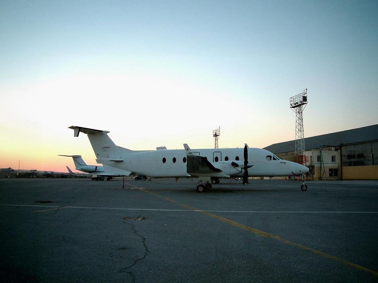
The Beechcraft 1900 is a low-wing monoplane constructed of metal with fully cantilevered wings and a T-tail empennage. It has a wingspan of 54 feet 6 inches, a length of 57 feet 10 inches, and a tail height of 14 feet 11 inches. The aircraft can accommodate 19 passengers plus crew, with baggage compartments located in the nose, forward cabin, and aft, allowing for a maximum baggage weight of 880 pounds.
Flight Controls
The flight controls of the Beechcraft 1900 include conventional push-pull control wheels for the ailerons and elevators, operated through a T-column. The rudder is controlled by pedals connected via linkages. The aircraft features adjustable trim tabs on the rudder, elevator, and ailerons, with the elevator trim being adjustable electrically.
Engines
The Beechcraft 1900 is powered by Pratt & Whitney PT6A-65B turbo-prop engines, each producing 1,100 shaft horsepower. The engine features a four-stage axial-flow and one centrifugal-flow compressor, with a gear reduction ratio of 17.6 to 1 between the power turbine and the propeller.
Landing Gear
The landing gear consists of a conventional air-oil strut system, with the main gear retracting forward into the nacelle and the nose gear retracting aft. The hydraulic system operates at a pressure of 3,000 psi for gear extension and retraction, with safety mechanisms to prevent accidental retraction on the ground.
Propeller System
The aircraft is equipped with a four-blade, constant-speed, full-feathering propeller system. The propeller pitch is controlled by engine oil pressure, and the system includes features for reversing and ground fine positions to enhance deceleration during landing.
Safety notes
- Ensure understanding of emergency exit locations and procedures.
- Monitor oil pressure; L/R OIL PRESS annunciator illuminates below 60 psi.
- Autofeather system must be armed for takeoff, climb, approach, and landing.
Full document text
BE-1900 Systems Airline Transport Pilot Oral Exam Guide—BE-1900 Systems by Michael D. Hayes Copyright © 2020 Aviation Supplies & Academics, Inc. All rights reserved. The material contained herein may be reproduced when used in conjuction with the Airline Transport Pilot Oral Exam Guide by Michael D. Hayes (OEG-ATP5). Aviation Supplies & Academics BE-1900 Systems 2 The following questions reference the Beechcraft 1900-C systems. These questions are representative of what you are required to know about your aircraft systems. Review your aircraft’s AFM for answers specific to the airplane your checkride will take place in. The blank lines can be used to document the information for air- craft you will be flying or testing in other than the BE-1900. A. Airframe 1. Describe the airframe of the BE-1900. (AFM) Low-wing monoplane constructed of metal with fully cantilevered wings and a T-tail empennage. _____________________________________________________ _____________________________________________________ _____________________________________________________ 2. What are the general dimensions of the BE-1900? (AFM) Wingspan—54 feet 6 inches ____________________________ Length—57 feet 10 inches ____________________________ Tail height—14 feet 11 inches ____________________________ 3. Describe the aircraft seating arrangement. (AFM) Seating is available for 19 passengers plus crew. _____________________________________________________ _____________________________________________________ 4. Where are the baggage compartments located and what is the maximum amount of weight allowed in each? (AFM) Nose—located in nose and accessed by opening a door on left side of fuselage; unpressurized and accommodates 150 lbs of baggage. Forward cabin—located opposite forward door and aft of the crew compartment. 250-lb weight capacity. Hangar in compart- ment: 100 lbs. Continued Aviation Supplies & Academics BE-1900 Systems 3 Aft—located at the rear of the cabin; separated from passenger compartment by a solid bulkhead; 880 pounds forward of cargo net and 630 pounds between cargo net and aft bulkhead. _____________________________________________________ _____________________________________________________ _____________________________________________________ _____________________________________________________ _____________________________________________________ _____________________________________________________ 5. Where are the emergency exits? (AFM) Three emergency exit doors are provided. One is located on the left side of the fuselage at the trailing edge of the wing. The other two are located on the right side of the fuselage at the leading and trailing edges of the wing. _____________________________________________________ _____________________________________________________ _____________________________________________________ _____________________________________________________ B. Flight Controls 1. Describe how the ailerons, elevators and rudders are operated. (AFM) Conventional push-pull control wheels interconnected by a T-column operate the ailerons and elevators. The rudder is oper- ated by rudder pedals, which are interconnected by linkages below the floor. All three systems are connected to their respective control surfaces through push rod and cable-bellcrank systems. _____________________________________________________ _____________________________________________________ _____________________________________________________ _____________________________________________________ Aviation Supplies & Academics BE-1900 Systems 4 2. What trim tabs are provided? (AFM) Adjustable trim tabs are located on the rudder, elevator, and ailerons. Trim tab controls are located on the center pedestal. All trim tabs can be manually adjusted. The elevator trim can also be adjusted electrically by moving a thumb switch on each control wheel. An ELEV TRIM ON/OFF is located on the pedestal. _____________________________________________________ _____________________________________________________ _____________________________________________________ _____________________________________________________ 3. What is the function of the yaw damper system? (AFM) The yaw damper senses heading changes (compass system input) and corrects, through use of a servo, by deflecting the rudder in the necessary direction and stabilizing the yaw axis of the airplane. _____________________________________________________ _____________________________________________________ _____________________________________________________ C. Annunciator System 1. What does the annunciator system consist of? (AFM) a. Warning annunciator panel— centrally located on glareshield panel, red readout. b. Caution/advisory annunciator panel—on center subpanel with yellow caution lights and green advisory lights. c. Two red master warning flashers—on glareshield directly in front of each pilot. d. Two yellow master caution flashers—inboard of the master caution flashers. e. Press-to-test switch—to the right of warning annunciator panel. _____________________________________________________ _____________________________________________________ _____________________________________________________ Aviation Supplies & Academics BE-1900 Systems 5 2. If a fault occurs that requires immediate attention, what indicator lights will illuminate? (AFM) a. Appropriate red warning flasher in the warning annunciator panel illuminates. b. Both master warning flashers begin flashing. c. Illuminated light in warning annunciator panel remains illumi- nated until fault is corrected. d. Master warning flashers can be extinguished by pressing the face of either flasher (even if fault has not been corrected). Will illuminate again if another warning annunciator illuminates. _____________________________________________________ _____________________________________________________ _____________________________________________________
Show full textShow less
_____________________________________________________ 3. If a fault occurs that requires attention but not imme- diate action, what indicator lights will illuminate? (AFM) a. Appropriate yellow caution flasher in the caution/advisory panel illuminates. b. Both master caution flashers begin flashing. c. Illuminated caution annunciator in the caution/advisory annun- ciator panel remains illuminated until fault is corrected. d. Master caution flashers can be extinguished by pressing the face of either flasher (even if fault has not been corrected). Will illuminate again if another caution annunciator illuminates. _____________________________________________________ _____________________________________________________ _____________________________________________________ _____________________________________________________ Aviation Supplies & Academics BE-1900 Systems 6 4. When will the annunciator panel automatically go into “dimming” mode? (AFM) The annunciator panel will automatically activate the dimming mode when all of the following conditions are met: a. A generator is online. b. The overhead floodlights switch is in the OFF position. c. The pilot flight lights switch is in the ON position. d. The ambient flight level in the cockpit is below a preset value. _____________________________________________________ _____________________________________________________ _____________________________________________________ _____________________________________________________ D. Flaps 1. Describe the flap system. (AFM) A four-position single-slotted flap system is provided, two on each wing. One is located on the outboard wing panel and one is located on the center section. Each individual flap is mounted on two tracks attached to the rear wing spar. Anti-friction rollers attached to the flap roll in the slots provided in the flap tracks. _____________________________________________________ _____________________________________________________ _____________________________________________________ _____________________________________________________ _____________________________________________________ 2. How are the flaps operated? (AFM) An electric motor powers a gearbox located on the forward side of the rear spar at the centerline of the aircraft. The gearbox turns four flexible driveshafts coupled to jackscrews, one of which oper- ates each flap. _____________________________________________________ _____________________________________________________ Aviation Supplies & Academics BE-1900 Systems 7 3. What are the different flap settings? (AFM) Four detents: UP, TAKEOFF, APPROACH, LANDING. Interme- diate flap positions not available. _____________________________________________________ 4. Which generator bus provides power to the flap motor? (AFM) The left generator bus. ____________________________ 5. What protection is provided in the event of a flap asymmetry? (AFM) Power is automatically disconnected to the flap motor in the event of a malfunction that would result in any flap being three to six degrees out of phase with the other flaps. _____________________________________________________ _____________________________________________________ _____________________________________________________ _____________________________________________________ E. Landing Gear 1. Describe the main and nose gear assemblies on this aircraft. (AFM) The main gear consists of a conventional air-oil strut which pivots between main structural ribs on the nacelle and retracts forward into the nacelle. The nose gear consists of a conventional air-oil strut installed in the nose which pivots on two longitudinal fuse- lage members and retracts aft. _____________________________________________________ _____________________________________________________ _____________________________________________________ _____________________________________________________ Aviation Supplies & Academics BE-1900 Systems 8 2. Describe the hydraulic extension and retraction of the landing gear. (AFM) Extension and retraction is accomplished by using actuators located on each gear assembly powered by the hydraulic system. The system’s electric motor drives a hydraulic pump, which directs hydraulic fluid to the extension or retraction side of the hydraulic actuators. The system is pressurized to 3,000 psi. _____________________________________________________ _____________________________________________________ _____________________________________________________ _____________________________________________________ 3. What methods are used to prevent accidental gear retraction while on the ground? (AFM) a. A safety switch is located on the right main landing gear that opens a control circuit when the gear strut is compressed. b. A mechanical down lock hook holds the landing gear handle in the “DOWN” position. The hook automatically disengages when the airplane leaves the ground. It can be manually overridden in case of a malfunction, by pressing the red downlock release button. _____________________________________________________ _____________________________________________________ _____________________________________________________ _____________________________________________________ _____________________________________________________ 4. What indicating system is used to advise the pilot of the gear position? (AFM) Landing gear position is provided by individual green GEAR DOWN indicator lights located on the pilot’s right subpanel, labeled NOSE, L and R. A red in-transit light is also provided, located inside the clear landing gear control handle. _____________________________________________________ _____________________________________________________ _____________________________________________________ _____________________________________________________ Aviation Supplies & Academics BE-1900 Systems 9 5. What conditions will result in the gear horn sounding and the red lights in the landing gear control handle to illuminate? (AFM) The warning horn will sound and the landing gear control handle lights will illuminate if the flap control handle is positioned up or down, to and including APPROACH and either or both power levers are retarded with the gear not down and locked. The red lights in the handle will also illuminate when the gear is in transit, the gear is unsafe (microswitches do not agree with position of gear handle), or when the power levers are below a preset N1 value with the gear up. _____________________________________________________ _____________________________________________________ _____________________________________________________ _____________________________________________________ _____________________________________________________ 6. How is the landing gear locked in the up position? (AFM) Hydraulic system pressure performs the uplock function and holds the gear in the UP position. _____________________________________________________ _____________________________________________________ 7. The upward travel of the landing gear is stopped when what condition is satisfied? (AFM) When a hydraulic pressure of 2,775 psi is obtained, a pressure switch removes power to the hydraulic pump motor. _____________________________________________________ _____________________________________________________ 8. What would cause the landing gear motor to cycle in flight? (AFM) When hydraulic system pressure drops below 2,320 psi. _____________________________________________________ Aviation Supplies & Academics BE-1900 Systems 10 9. How is manual extension of the gear accomplished? (AFM) An alternate extension handle is provided (located on the floor to the right of the captain’s seat) which uses hydraulic fluid from a secondary reservoir directed to the extend side of the hydraulic actuators. Remove the alternate extension handle from clip, and begin to pump. Continue to pump until three green “gear down” indicator lights are illuminated. This procedure requires approxi- mately 80 strokes to extend and lock the gear. Note: Gear handle must be down, landing gear relay circuit breaker must be pulled, and airspeed must be less than 180 knots. _____________________________________________________ _____________________________________________________ _____________________________________________________ _____________________________________________________ _____________________________________________________ 10. How is nosewheel steering accomplished? (AFM) A mechanical linkage connected to the rudder pedals is provided. The steering system is disconnected from the rudder control system when the airplane becomes airborne. A power steering system may also be installed, consisting of an electric motor that drives a hydraulic pump, a hydraulic actuator, and a servo valve assembly. _____________________________________________________ _____________________________________________________ F. Engines 1. What type of engines are installed on the BE-1900? (AFM) Pratt & Whitney PT6A-65B, reverse airflow, free turbine, turbo- prop engines. _____________________________________________________ Aviation Supplies & Academics BE-1900 Systems 11 2. The engine contains how many drive shafts? (AFM) Two; one compressor (gas generator) shaft and one power turbine shaft. _____________________________________________________ 3. How many and what type of compressor stages are used in this engine? (AFM) Four axial-flow stages and one centrifugal-flow stage. _____________________________________________________ 4. What type of combustion chamber is used? (AFM) Annular ____________________________ 5. What types of power and compressor turbines are used on this engine? (AFM) Power turbine—two stage axial flow reaction turbine _____________________________________________________ Compressor (gas generator) turbine—single stage axial flow reac- tion turbine _____________________________________________________ 6. What is the engine shaft horsepower rating? (AFM) 1,100 SHP ____________________________ 7. What is the compressor (gas generator) shaft rotational speed (N1) limits for the following operating conditions: Takeoff, Maximum Continuous, Cruise Climb, Maximum Cruise and Transient? (AFM) 104% N1 (39,000 rpm) _____________________________________________________ 8. What is the approximate gear reduction ratio between the power turbine and the propeller? (AFM) 17.6 to 1 ____________________________ Aviation Supplies & Academics BE-1900 Systems 12 9. What are some of the items located on the engine accessory gearbox? (AFM) Starter/generator, engine oil pump, N1 tachometer generator, low- and high-pressure fuel boost pumps, fuel control unit. _____________________________________________________ _____________________________________________________ 10. Describe the engine lubrication system. (AFM) An integral tank between the engine air intake and the accessory case contains oil used to cool as well as lubricate the engine. Engine oil temperature is maintained within operational limits by an engine oil radiator located inside the lower nacelle. _____________________________________________________ _____________________________________________________ _____________________________________________________ _____________________________________________________ 11. What condition will cause the L/R OIL PRESS annunciator to illuminate in flight? (AFM) Oil pressure has dropped below 60 psi. _____________________________________________________ 12. What is the function of the “auto ignition” switches? (AFM) When selected to ON, they provide automatic ignition to prevent engine loss due to combustion failure. Normally used during takeoff and landing as well as when operating in turbulence, icing, and heavy precipitation conditions. _____________________________________________________ _____________________________________________________ _____________________________________________________ _____________________________________________________ Aviation Supplies & Academics BE-1900 Systems 13 13. Describe the propulsion system controls for this airplane. (AFM) Three sets of controls are provided: a. Power levers— control engine power. b. Condition levers— control idle cutoff function of the fuel control unit; limits idle speed to 58% N1 for low idle, or 72% for high idle. Three positions: FUEL CUTOFF, LOW IDLE and HIGH IDLE. c. Propeller levers— control constant speed propellers through a primary governor. _____________________________________________________ _____________________________________________________ _____________________________________________________ _____________________________________________________ 14. Describe how the power levers operate. (AFM) The power levers control engine power by operation of the gas generator (N1) governor in the fuel control unit. An increase in N1 rpm causes an increase in engine power. _____________________________________________________ _____________________________________________________ _____________________________________________________ 15. What type of engine instrumentation is provided? (AFM) a. ITT indicators—indicate engine gas temperature between compressor and power turbines. b. Torque meters—indicate foot-pounds of torque applied to propeller. c. Propeller tachometers (N2 speed)—indicate prop rpm. d. Gas generator (N1) tachometers—indicate rotational speed of compressor shaft in percent of rpm based on 37,468 rpm at 100%. e. Fuel flow gauges—indicate fuel flow in pounds per hour times 100. Continued Aviation Supplies & Academics BE-1900 Systems 14 f. Combination oil temperature/pressure gauges—pressure on the right side and temperature on the left. _____________________________________________________ _____________________________________________________ _____________________________________________________ _____________________________________________________ _____________________________________________________ G. Fire Detection 1. Describe the fire detection system. (AFM) Composed of the following: a. Two fire zone cables installed in each nacelle interconnected to form a continuous loop. b. A single control amplifier in flight compartment on forward bulkhead. c. A control circuit breaker placarded FIRE DET. d. Two toggle test switches on co-pilot’s inboard subpanel. _____________________________________________________ _____________________________________________________ _____________________________________________________ _____________________________________________________ 2. What is the function of the fire cable and control amplifier? (AFM) Heat sensitive cables are looped around the engines so as to monitor the most likely areas for fires to occur. If a fire were to occur, heating of the cable causes resistance to drop. The control amplifier will sense this drop and at a preset level, illuminate the red light in FIRE PULL “T” handle. _____________________________________________________ _____________________________________________________ _____________________________________________________ _____________________________________________________ Aviation Supplies & Academics BE-1900 Systems 15 3. How is fire extinguishing accomplished in this aircraft? (AFM) a. Pull the FIRE PULL “T” handle for the appropriate engine which will cause the system to arm. b. Raise the safety-wired clear plastic cover and press face of lens, which causes pyrotechnic cartridge to discharge. One pyrotechnic cartridge in each main gear wheel well. c. When fully discharged, yellow D light will illuminate. _____________________________________________________ _____________________________________________________ _____________________________________________________ 4. How is the fire detection/extinguishing system tested? (AFM) Two toggle-type test switches placarded ENG FIRE TEST—EXT TEST, one for the left system and one for the right system are provided. The switches test the circuitry of the fire extinguisher pyrotechnic cartridges. A successful test is indicated by illumina- tion of a yellow “D” light and the illumination of a green “OK” light on each fire extinguisher switch on the glareshield. _____________________________________________________ _____________________________________________________ _____________________________________________________ _____________________________________________________ Aviation Supplies & Academics BE-1900 Systems 16 H. Propeller 1. Describe the propeller system. (AFM) Conventional four-blade, composite, constant-speed, full-feath- ering, reversing, counter-weighted, variable-pitch propeller. The propeller is mounted on the reduction gearbox output shaft. Single- action, engine-driven propeller governors use engine oil pressure to control propeller pitch and speed. Engine oil pressure moves the propeller to high rpm (low-pitch) hydraulic stop and reverse posi- tions. Centrifugal counterweights, assisted by a feathering spring, move the propeller blades to low rpm (high-pitch) and into the feathered position. _____________________________________________________ _____________________________________________________ _____________________________________________________ _____________________________________________________ 2. Describe how the propeller levers operate. (AFM) Movement of the propeller lever positions a pilot valve that allows oil to be directed to or from the propeller hub, which results in an increase or decrease in propeller rpm. To feather a propeller, the propeller lever lifts a pilot valve to a position causing a complete dumping of high-pressure oil. This allows counterweights and feathering spring to change prop pitch. The propeller control levers range of operation is 1,400 to 1,700 rpm. _____________________________________________________ _____________________________________________________ _____________________________________________________ 3. What is “propeller ground fine” position used for? (AFM) Used to provide maximum deceleration on the ground during landing. Takes advantage of max available propeller drag. _____________________________________________________ _____________________________________________________ Aviation Supplies & Academics BE-1900 Systems 17 4. What controls the propeller blade angle while on the ground and in “ground fine”? (AFM) The condition levers. ____________________________ 5. How is propeller reversing accomplished? (AFM) Lift power levers past IDLE and GND FINE position. Power levers are now controlling engine power through the reverse range. _____________________________________________________ _____________________________________________________ 6. What is the function of the propeller low pitch stop? (AFM) The low pitch stop prevents the propeller from reversing in flight. _____________________________________________________ 7. Describe the function of the propeller synchrophaser, synchronizer and synchroscope. (AFM) a. Synchrophaser—positions propellers at a preset phase relation- ship which assists in decreasing cabin noise. First adjust prop levers or synchronization, then switch on. b. Synchronizer—matches the rpm of the slower propeller to the faster propeller. c. Synchroscope—instrument in the cockpit used to display difference in rpm between propellers. The gage consists of a small propeller that rotates in the direction of the higher rpm propeller. _____________________________________________________ _____________________________________________________ _____________________________________________________ Aviation Supplies & Academics BE-1900 Systems 18 8. What are the three types of propeller governors and what is their function? (AFM) a. Primary (constant speed) governor—mounted on the reduc- tion gear housing, controls the propeller throughout its normal operating range. The primary governor has authority within the 1,400 to 1,700 rpm range. b. Fuel topping—prevents the power turbine from overspeeding by reducing the amount of fuel to the fuel control unit. c. Overspeed governor—in the event of a constant-speed governor malfunction (requesting more than 1,700 rpm) the overspeed governor activates at 1,768 rpm and dumps oil pressure from the propeller to keep rpm from exceeding approximately 1,768 rpm. _____________________________________________________ _____________________________________________________ _____________________________________________________ _____________________________________________________ _____________________________________________________ 9. How do the propeller governors control rpm? (AFM) They utilize engine oil pressure. 10. What happens to propeller blade angle as oil enters the propeller hub? Leaves the hub? (AFM) As oil enters, it causes the propeller blade angle to decrease. As it leaves the hub, the propeller blade angle will increase. _____________________________________________________ _____________________________________________________ _____________________________________________________ 11. If a propeller overspeed occurs, what does this indicate? (AFM) A failure of the primary governor has occurred. _____________________________________________________ Aviation Supplies & Academics BE-1900 Systems 19 12. How does the autofeather system work and when must it be armed? (AFM) In the event of an engine failure, the autofeather system auto- matically dumps oil from the propeller servo, which enables the feathering spring and counterweights to start the feathering action of the blades. The autofeather system must be armed for takeoff, climb, approach and landing. _____________________________________________________ _____________________________________________________ _____________________________________________________ _____________________________________________________ 13. When does the autofeather system arm? (AFM) a. Autofeather switch is in the ARM position. b. Both power levers are greater than 88 to 91 percent N1. c. Torque is greater than 525 feet-pounds. _____________________________________________________ _____________________________________________________ 14. With the autofeather system armed, what will happen in the event of an engine failure? (AFM) When torque is less than 320 foot-pounds, the system will feather the propeller. _____________________________________________________ I. Fuel System 1. Describe the fuel tank system. (AFM) a. Two integral fuel tanks in each wing. b. Main tank extends from the nacelle to the wingtip; 241.3 gallons usable; filled from a port located near wing tip. c. Collector tank (located inside each main tank) is supplied fuel from the main tank by gravity feed and two jet transfer pumps. Ensures a constant fuel level in collector tank at normal flight attitudes. Continued Aviation Supplies & Academics BE-1900 Systems 20 d. Auxiliary tank is located between fuselage and nacelle; 92.3 gallons usable; filled from a port located inboard of nacelle. _____________________________________________________ _____________________________________________________ _____________________________________________________ _____________________________________________________ _____________________________________________________ 2. What are the different types of fuel pumps? (AFM) a. Engine-driven fuel pump—high-pressure, mounted on acces- sory case along with fuel control unit. b. Engine-driven primary boost pump—low-pressure, mounted on drive pad at aft accessory section. c. Electrically-driven standby pump—low pressure, located in bottom of collector tank sump. Serves as backup for engine driven pump; also provides cross-transfer fuel flow. d. Electrically-driven auxiliary fuel pumps—transfer fuel to the collector tank in same wing. _____________________________________________________ _____________________________________________________ _____________________________________________________ _____________________________________________________ _____________________________________________________ 3. What will happen in the event of an engine-driven pump failure? (AFM) Failure of the engine-driven, high-pressure fuel pump will result in an immediate engine flame-out. _____________________________________________________ _____________________________________________________ Aviation Supplies & Academics BE-1900 Systems 21 4. Where are the fuel drains located? (AFM) Six drains in each wing: • One drain for auxiliary tank located underside of wing inboard of nacelle. • Two drains for collector tank located outboard side of nacelle. • Two drains for main tank located underside of wing, outboard of nacelle. • One drain for fuel filter located underside of wing outboard of nacelle. _____________________________________________________ _____________________________________________________ _____________________________________________________ 5. How is fuel system venting accomplished? (AFM) Both the main and auxiliary fuel systems are vented through a recessed ram vent coupled to a protruding ram vent on the underside of wing tip. Recessed vent is ice resistant by design; protruding vent is heated to prevent icing. _____________________________________________________ _____________________________________________________ _____________________________________________________ _____________________________________________________ 6. Describe the operation of the fuel purge system. (AFM) The system uses a small purge tank pressurized by the engine compressor (P3) discharge air. On engine shutdown, the purge tank pressure forces excess fuel out of the engine fuel manifold lines, through the fuel nozzles and into the engine, where the fuel is burned. Usually results in a momentary surge in N1 gas generator rpm. _____________________________________________________ _____________________________________________________ _____________________________________________________ _____________________________________________________ Aviation Supplies & Academics BE-1900 Systems 22 7. Describe the fuel quantity indicators. (AFM) a. Capacitance type fuel quantity indication system. b. Fuel quantity indicators (left and right) indicate fuel (in pounds) remaining in respective fuel tanks. c. Compensates for changes in fuel density due to temperature changes. d. Maximum indication error of 3% full scale. e. Fuel quantity in auxiliary tanks determined by deflecting a spring-loaded fuel quantity switch to “Aux.” position. _____________________________________________________ _____________________________________________________ _____________________________________________________ _____________________________________________________ 8. How is fuel transferred from the fuel tanks to the engines? (AFM) Engine-driven fuel pumps (high-pressure and boost) draw fuel from the collector tank. The collector tank draws fuel from its respective main tank (unless fuel is being supplied from the auxil- iary tank). Auxiliary tank fuel should be used prior to using fuel in the main tanks. Accomplished by positioning auxiliary pump switches to AUTO. When no fuel is remaining in auxiliary tank, the pump automatically shuts off. _____________________________________________________ _____________________________________________________ _____________________________________________________ _____________________________________________________ _____________________________________________________ Aviation Supplies & Academics BE-1900 Systems 23 9. Proper fuel management in this aircraft requires fuel from the auxiliary tanks to be used before the main tank fuel. Why? (AFM) In the event of an auxiliary pump failure, the fuel remaining in the auxiliary tanks would not be available for flight. Backup or secondary pumps are not installed and it is not possible to gravity feed fuel from the auxiliary fuel tanks. _____________________________________________________ _____________________________________________________ _____________________________________________________ 10. Describe how you would cross-transfer fuel from one tank to another. (AFM) a. Standby pump switches in OFF position. b. Move lever lock switch (TRANSFER FLOW -OFF) from the center OFF position to the left or right, depending on direction of flow. c. Cross-transfer valve is now open which energizes standby pump on the side from which cross-feed is desired. Green FUEL TRANSFER annunciator on caution/advisory panel will illuminate. _____________________________________________________ _____________________________________________________ _____________________________________________________ 11. How do the firewall shutoff valves work? (AFM) Two firewall shutoff valves are provided, one for each engine. The valves are controlled by the FIRE PULL handles located on the upper center instrument panel. When the FIRE PULL handle is pulled, it closes the firewall shutoff valve and arms the fire extinguisher. _____________________________________________________ _____________________________________________________ Aviation Supplies & Academics BE-1900 Systems 24 12. How does the fuel control unit work? (AFM) The fuel control unit regulates fuel flow to the engine by metering fuel to the fuel nozzles. It compares power and condition lever position to the selected N1 (gas generator speed). _____________________________________________________ _____________________________________________________ 13. How is fuel system icing prevented? (AFM) Via an oil-to-fuel heat exchanger, located on the engine accessory case which operates continuously. _____________________________________________________ J. Electrical System 1. Describe the electrical system. (AFM) a. Negatively-grounded 28-volt DC system (grounded to aircraft structure). b. 23 amp/hour NiCad battery, or optional 34 amp/hour air-cooled NiCad battery. c. Two 28-volt, 300 amp starter/generators supply all power to DC buses and the battery (to maintain charge). d. AC power is provided by two 115/26 VAC, 400 Hz inverters. _____________________________________________________ _____________________________________________________ _____________________________________________________ 2. Where is the battery located? (AFM) It is located in the right wing root between the fuselage and the right engine nacelle. 3. What volts/amps are required for starting when using an external power cart? (AFM) External power carts should be capable of providing 28.0–28.4 volts, and a minimum of 1,000 amps momentarily and 300 amps continuously. _____________________________________________________ Aviation Supplies & Academics BE-1900 Systems 25 4. The electrical system consists of several buses. What are they? (AFM) Two generator buses, two center buses, a battery bus, and a triple- fed bus are provided. _____________________________________________________ 5. Describe how electrical power is distributed among the various buses. (AFM) The electrical system uses the triple-fed bus arrangement, which means that most electrical system buses receive power from three power sources. Each individual bus is powered by its respective source—the battery, the left generator, and the right generator. In normal operation, all buses are automatically tied into a single loop. A hot battery bus provides power for essential equipment such as cockpit emergency lighting, threshold lighting, fire extin- guishing system and the main entry door. _____________________________________________________ _____________________________________________________ _____________________________________________________ _____________________________________________________ 6. What other equipment is located on the hot battery bus? (AFM) Left and right firewall fuel shut-off valves, external power annun- ciator, forward baggage door annunciator, control wheel clock, pitot heater right side, ground communication power. _____________________________________________________ _____________________________________________________ 7. Describe the function of the main starter/generators. (AFM) The starter/generators act as starters for the engines up to 52% N1. Above that value, they assume the function of a generator produc- ing 28 volts/300 amps to power the aircraft electrical buses. _____________________________________________________ _____________________________________________________ Aviation Supplies & Academics BE-1900 Systems 26 8. How is generator output monitored? (AFM) Two volt/loadmeters are provided to monitor generator output and battery charge. _____________________________________________________ 9. What are the functions of the two generator control units (GCU)? (AFM) a. Voltage regulation (28.25 ±.25 volts). b. Line contactor control (connection of generators to electrical buses). c. Overvoltage protection (over 32 volts). d. Load sharing and paralleling (within 10%). e. Reverse current protection. f. Cross start current limiting. _____________________________________________________ _____________________________________________________ _____________________________________________________ 10. Three high-current-sensing devices control three bus tie relays. What is their function? (AFM) Also known as HEDs (hall effect devices), these sensors actuate by opening the affected bus tie anytime they sense a current of 275 amps or higher supplied from a single source. They effectively isolate the bus requiring the high current and allow the remaining power sources to continue functioning as a system. _____________________________________________________ _____________________________________________________ _____________________________________________________ _____________________________________________________ Aviation Supplies & Academics BE-1900 Systems 27 11. What is the function of a line contactor relay? (AFM) Line contactor relays connect power from the generators to the electrical system buses. They are also used as reverse-current devices by the generator control units. The relays prevent the generators from absorbing power from the bus when the generator voltage is less than the bus voltage. _____________________________________________________ _____________________________________________________ _____________________________________________________ _____________________________________________________ K. Environmental 1. Describe the pressurization system on this aircraft. (AFM) The pressurization system uses bleed air from the compressor section of each engine to pressurize the cabin. The system provides a pressure differential of 4.8 ± .1 psi. The bleed air is precooled by a heat exchanger and two valves before it enters the air cycle machine (ACM), or bypasses the ACM and is ducted to the cabin. Bleed air flow and pressure are controlled from the cockpit by the environmental bleed air shutoff valves. _____________________________________________________ _____________________________________________________ _____________________________________________________ _____________________________________________________ 2. What is the function of the pressurization controller? (AFM) The adjustable pressurization controller commands modulation of the outflow valve. The controller has an inner and outer scale. The outer scale indicates cabin pressure altitude that the controller will Continued Aviation Supplies & Academics BE-1900 Systems 28 maintain (set by the pilot). The inner scale indicates the maximum ambient pressure altitude the airplane can fly without causing the cabin pressure altitude to exceed the value set on the outer scale. _____________________________________________________ _____________________________________________________ _____________________________________________________ _____________________________________________________ 3. What is the function of the outflow valves? (AFM) a. Control cabin pressure by venting excess air overboard. b. Provide both positive and negative pressure relief. c. Provide a means of “dumping” the cabin pressure. _____________________________________________________ _____________________________________________________ _____________________________________________________ 4. How is pressurization of the aircraft indicated in the cockpit? (AFM) The actual cabin pressure altitude is indicated by a cabin altimeter, mounted on the forward panel between caution/annunciator panel and pedestal. A cabin vertical speed indicator is also provided which indicates the rate at which cabin pressure altitude is chang- ing; it is located immediately to the left of the cabin altimeter. _____________________________________________________ _____________________________________________________ _____________________________________________________ _____________________________________________________ Aviation Supplies & Academics BE-1900 Systems 29 5. What is the function of the cabin pressure switch? (AFM) The cabin pressure switch allows the pilot to pressurize the aircraft, depressurize the aircraft or test the system. A three-posi- tion switch labeled DUMP, PRESS, and TEST controls the system. The DUMP position holds the outflow valves open and depressur- izes the cabin. The PRESS position allows the outflow valves to be controlled by the pressurization controller. The TEST position opens the landing gear safety switch circuit, allowing the outflow valves to close. This feature allows the aircraft to be pressurized on the ground. The switch is located forward of the pressurization controller on the pedestal. _____________________________________________________ _____________________________________________________ _____________________________________________________ _____________________________________________________ 6. Describe the operation of the pressurization system. (AFM) a. Prior to takeoff, adjust the cabin altitude selector knob so that 1,000 feet above planned cruise pressure altitude is displayed on indicator. b. Ensure that the CAB ALT scale indicates an altitude of at least 500 feet above takeoff field pressure altitude. c. Adjust rate controller knob as desired (setting index mark at 12 o’clock position results in 500-fpm cabin rate of climb; most comfortable). d. Ensure that cabin pressure switch is in PRESS position. e. The cabin pressure altitude will climb at the selected rate and once established at the pre-selected pressure altitude, the system will maintain that selected altitude. _____________________________________________________ _____________________________________________________ _____________________________________________________ _____________________________________________________ _____________________________________________________ Aviation Supplies & Academics BE-1900 Systems 30 7. Describe how the pressurization system reacts to a change in altitude. (AFM) If the altitude selected on the ACFT ALT scale is not adjusted, and the aircraft climbs, cabin-to-ambient pressure differential will reach the pressure relief setting of the outflow valves. The outflow valves will override the pressurization controller in order to main- tain cabin pressure differential to 4.8 psi ± .1 psi. _____________________________________________________ _____________________________________________________ _____________________________________________________ _____________________________________________________ 8. What mechanism is used to prevent the aircraft from being pressurized on the ground? (AFM) When the aircraft is on the ground, the landing gear safety switch on the left gear signals the outflow valves to modulate to the full open position. _____________________________________________________ _____________________________________________________ _____________________________________________________ 9. How does the altitude warning feature work? (AFM) A pressure-sensing switch, located on the electrical panel of the forward aft bulkhead, will close anytime it senses a cabin pressure altitude of 12,500 feet resulting in illumination of the CABIN ALTITUDE annunciator. _____________________________________________________ _____________________________________________________ _____________________________________________________ 10. What will happen if both bleed air valves are positioned to INST and ENVIR OFF? (AFM) Loss of pressurization will occur. No bleed air is being supplied to the pressure vessel. _____________________________________________________ Aviation Supplies & Academics BE-1900 Systems 31 11. How can the pilot ventilate the aircraft if it is unpressurized? (AFM) A manually-controlled valve, located in the nose ram air duct, can be opened to supply ambient air to the cabin when the airplane is not pressurized. Air enters the airplane through the ram air door solenoid valve and the manual valve when the cabin pressure control switch is set to “dump.” _____________________________________________________ _____________________________________________________ _____________________________________________________ _____________________________________________________ 12. How is the aircraft heated? (AFM) Engine bleed air is used to heat the cabin. The bleed air enters the cabin distribution ducts for heating through the air cycle machine and ejector bypass valves. When heating is required, the air cycle machine bypass valve opens and modulates output of the ACM. When maximum heating is required, the ACM bypass valve modu- lates to the full open position and then directs current to the ejector bypass valve, which also modulates to the full open position. The heated air is ducted to outlets in the cabin sidewalls, crew vents and defroster. _____________________________________________________ _____________________________________________________ _____________________________________________________ 13. How is the aircraft cooled? (AFM) Both an air cycle system and a vapor cycle system are used to provide cabin cooling. When the air cycle system is providing maximum cooling, a signal is automatically generated by the temperature control circuitry resulting in the vapor cycle system coming online to provide further cooling. For maximum cooling, both the ejector bypass valve and the ACM bypass valves are closed and the VCM is online. _____________________________________________________ _____________________________________________________ _____________________________________________________ Aviation Supplies & Academics BE-1900 Systems 32 14. Describe the air cycle system. (AFM) Air cycle machines use engine bleed air to turn a compressor that compresses air, resulting in a rise in temperature. The high- temperature air is routed through heat exchangers to remove some of the excess heat, then sent to the ACM expansion turbine. As the air passes through the turbine, it rotates the turbine and the impeller. After the compressed air performs the work of turning the turbine, it undergoes a pressure and temperature drop result- ing in an air temperature significantly lower than the ambient air temperature. _____________________________________________________ _____________________________________________________ _____________________________________________________ _____________________________________________________ _____________________________________________________ 15. Describe the vapor cycle system. (AFM) The vapor cycle system consists of the following: a. Compressor—increases pressure of refrigerated gas when it is in vapor form. Provides force necessary to circulate gas through the system. b. Condensing coil and blower assembly—removes heat from compressed high-pressure, high-temperature refrigerated gas coming from the compressor. Changes state from gas to liquid. c. Thermostatic expansion valve—metering device that directs high-pressure, low-temperature refrigerated liquid to the evaporator. d. Evaporator—lowers pressure of refrigerated liquid causing a change in state from liquid to gas; results in maximum cooling. e. Evaporator coil—air is routed over coil where heat is removed before being returned to the cabin. f. Low-pressure, low-temperature refrigerant is then returned to the compressor. _____________________________________________________ _____________________________________________________ _____________________________________________________ Aviation Supplies & Academics BE-1900 Systems 33 _____________________________________________________ _____________________________________________________ _____________________________________________________ _____________________________________________________ 16. What conditions must be met in order for the VCM to operate? (AFM) Outside air temperature of greater than 45°F, ACM bypass valve fully closed, and the right engine is operating at 62% N1. _____________________________________________________ _____________________________________________________ _____________________________________________________ L. Oxygen 1. Describe the oxygen system on this aircraft. (AFM) a. Consists of two 76.6 foot cylinders. b. Mounted under the floor of the nose baggage compartment. c. Two cylinder pressure gauges on copilot right subpanel. d. Pressure gage indicating pressure to the cabin masks right side of instrument panel. _____________________________________________________ _____________________________________________________ _____________________________________________________ _____________________________________________________ 2. What is the system pressure for the oxygen system? (AFM) 1,850 psi at 70°F. ____________________________ Aviation Supplies & Academics BE-1900 Systems 34 3. Describe the oxygen system for the crew. (AFM) a. Constant-flow type (O2 flows continuously). b. Cylinder-mounted constant-flow regulators with reduced pressure output. c. Two oxygen outlets and associated masks located behind the overhead light control panel. d. Removal/insertion of a lanyard pin controls oxygen flow to the masks. _____________________________________________________ _____________________________________________________ _____________________________________________________ _____________________________________________________ 4. How are the two oxygen cylinders actuated? (AFM) A push pull control knob labeled OXYGEN—PULL ON, simulta- neously actuates the two oxygen cylinders. _____________________________________________________ _____________________________________________________ 5. Describe the passenger oxygen masks. (AFM) a. Constant-flow type (O2 flows continuously). b. Altitude compensating. c. Constant-flow regulator varies flow rate to masks based on altitude (mounted on left side of airplane, aft of forward pressure bulkhead). _____________________________________________________ _____________________________________________________ _____________________________________________________ Aviation Supplies & Academics BE-1900 Systems 35 6. How is oxygen flow to the passenger masks initiated? (AFM) A push-pull control knob labeled CABIN OXYGEN—PULL ON, governs the flow of oxygen to the passenger oxygen outlets. The passenger must remove a lanyard valve pin from the mask to start the flow of oxygen. _____________________________________________________ _____________________________________________________ _____________________________________________________ 7. What mechanism causes the passenger mask container door to open? (AFM) When the push-pull control knob is pulled out, a surge valve will initially allow high pressure to reach the mask container door, causing the door to open and allowing access to the mask. _____________________________________________________ _____________________________________________________ _____________________________________________________ M. Pitot Static System 1. Describe the pitot-static system on this airplane. (AFM) a. Two pitot tubes (pilot and copilot). b. Two separate sources of normal static air; one for pilot and one for copilot. c. Normal static air provided by static ports located on the pitot/ static masts. d. Alternate static source is provided; alternate line obtains static air from each side of the lower nose. _____________________________________________________ _____________________________________________________ _____________________________________________________ _____________________________________________________ Aviation Supplies & Academics BE-1900 Systems 36 2. Are the static lines interconnected? (AFM) Yes; the two static sources are connected together so that, in the event of one source becoming obstructed, both pilot and copilot instruments will still be functional from the remaining source. _____________________________________________________ _____________________________________________________ _____________________________________________________ 3. In the event of a failure of either pilot’s normal static air source, what procedure should be followed? (AFM) The alternate static source should be selected by lifting a spring- clip retainer off the pilot or copilot’s static air source valve switch, and then moving that switch to the ALTERNATE position. Note: When using an alternate static air source, the altimeter, airspeed and vertical speed instrument indications will be affected. _____________________________________________________ _____________________________________________________ _____________________________________________________ _____________________________________________________ N. Engine Bleed Air Pneumatic System 1. What are some of the aircraft systems that utilize engine bleed air? (AFM) Cabin pressurization, heating and cooling, brake deice, deice boots, hydraulic system, vacuum system. _____________________________________________________ 2. Bleed air is obtained from which engine stage? (AFM) P3 ____________________________ 3. What is the approximate temperature of bleed air? (AFM) 800°F. Precooled to 450°F before use by the environmental system (pressurization/air conditioning). _____________________________________________________ Aviation Supplies & Academics BE-1900 Systems 37 4. Describe the bleed air warning system. (AFM) EVA tubing (plastic) pressurized to 18 psi is co-located with the bleed air ducting running from the engines to the cabin. Any excessive heat caused by a bleed air duct rupture would cause the EVA tubing to melt resulting in an immediate drop in pres- sure. The drop in pressure causes a switch in the line to close illuminating the L or R BL AIR FAIL annunciator in the warning annunciator panel. _____________________________________________________ _____________________________________________________ _____________________________________________________ 5. What is the function of the bleed air valve switches? (AFM) In the event of a bleed-air line failure, bleed air for that particular line may be shut off by positioning the BLEED AIR VALVE switch on the FO’s left subpanel in the INSTR and ENVIR OFF position. _____________________________________________________ _____________________________________________________ 6. What is normal pneumatic system pressure regulated at? (AFM) 18 psi ____________________________ 7. How is pneumatic pressure used to create vacuum for the vacuum system? (AFM) Vacuum is created by directing pneumatic air through a bleed air ejector. _____________________________________________________ Aviation Supplies & Academics BE-1900 Systems 38 8. What aircraft systems use vacuum for operation? (AFM) a. Aircraft flight instruments (directional gyro and attitude indicator). b. Surface deice system (deflates deice boots). c. Pressurization system (outflow valves, pressurization controller). _____________________________________________________ _____________________________________________________ _____________________________________________________ 9. What is the vacuum system pressure regulated at? (AFM) 4.3" to 5.9" Hg ____________________________ O. Ice Protection 1. What are the two basic types of ice protection equipment? (AFM) Anti-ice and deice. ____________________________ 2. What are some of the anti-ice systems on this airplane? (AFM) Engine air inlet lip heat, inertial separators, pitot heat, static port heat, windshield heat, stall warning vane heat, fuel vent heat, oil-to-fuel heat exchanger. _____________________________________________________ _____________________________________________________ 3. What are some of the deice systems on this airplane? (AFM) Brake deice, surface deice (boots), propeller deice. _____________________________________________________ Aviation Supplies & Academics BE-1900 Systems 39 4. What effect does placing the windshield anti-ice switch in the NORM and HI positions have? (AFM) NORM—A major portion of the windshield is supplied with heat. _____________________________________________________ HI—A higher level of heat is supplied to a smaller area of the windshield. _____________________________________________________ 5. Describe the propeller electric deice system. (AFM) a. Electrically-heated deice boots b. Slip rings and brush block assemblies c. Timer for automatic operation d. Dual-scale ammeter e. Two prop deice control circuit breakers f. Circuit breakers and current limiters for protection of prop deice boot wiring g. Two switches for auto or manual control of system _____________________________________________________ _____________________________________________________ _____________________________________________________ _____________________________________________________ 6. Describe the operational sequence of the propeller deice system when the switch is in the AUTO position. (AFM) When the switch placarded PROP-AUTO is selected to AUTO, the propeller automatic timer supplies power to the heating elements of one propeller for 90 seconds. Then it automatically switches over to supply power to the other propeller for 90 seconds. Each cycle takes approximately 3 minutes. _____________________________________________________ _____________________________________________________ _____________________________________________________ Aviation Supplies & Academics BE-1900 Systems 40 7. Describe the operational sequence of the propeller deice system when the switch is held in the MANUAL position. (AFM) When the switch placarded PROP-MANUAL is held in the MANUAL position, the heating elements on both of the propellers are supplied power. The switch should be held in the MANUAL position for approximately 90 seconds. _____________________________________________________ _____________________________________________________ _____________________________________________________ _____________________________________________________ 8. How is normal operation of the propeller deice system be verified in the cockpit? (AFM) With the propeller deice switch in the ON position, normal operation of the propeller deice system can be accomplished by monitoring normal current flow to each propeller blade of 26 to 32 amps on a dual-scale ammeter located on the overhead panel. _____________________________________________________ _____________________________________________________ _____________________________________________________ _____________________________________________________ 9. What type of ice protection is provided for the engines? (AFM) a. Engine air inlet— engine exhaust is used for heating air inlet lips. The hot exhaust is collected by a scoop and ducted downward to connect with inlet lip. b. Engine anti-ice—inertial separation system is provided in each engine air duct; prevents moisture from entering the engine inlet plenum during icing conditions. _____________________________________________________ _____________________________________________________ Aviation Supplies & Academics BE-1900 Systems 41 10. What aerodynamic surfaces are protected by the surface deice system? (AFM) The leading edges of the wings, stabilons, and horizontal stabilizers. _____________________________________________________ 11. Describe the operation of the surface deice system. (AFM) Pressure-regulated engine bleed air supplies the necessary pres- sure to inflate the boots. The vacuum needed to hold the boots in the deflated position is created by bleed air directed through a venturi ejector. A distributor valve controls the inflation and defla- tion cycles. _____________________________________________________ _____________________________________________________ _____________________________________________________ _____________________________________________________ 12. Describe the sequence of deice boot inflation when the surface deice switch is in the SINGLE position. (AFM) a. Distributor valve opens to send bleed air to outboard wing boots for 6 seconds. b. Electronic timer switches distributor to deflate outboard boots. c. Electronic timer opens distributor to inflate inboard wing boots, horizontal stabilizer and stabilon boots for 6 seconds then deflates. Cycle is now complete. _____________________________________________________ _____________________________________________________ _____________________________________________________ _____________________________________________________ Aviation Supplies & Academics BE-1900 Systems 42 13. Describe the sequence of deice boot inflation when the surface deice switch is held in the MANUAL position. (AFM) All the boots will inflate simultaneously and remain that way until the switch is returned to the OFF position. _____________________________________________________ _____________________________________________________ 14. When must the auto ignition system be armed? (AFM) During takeoff, landing, turbulence, and anytime the aircraft is being operated in icing conditions or heavy precipitation. Also used for takeoffs from contaminated runways. Prevents engine loss due to combustion failure (engine flame out). _____________________________________________________ _____________________________________________________ _____________________________________________________ _____________________________________________________ BE-1900 Limitations Airline Transport Pilot Oral Exam Guide—BE-1900 Systems by Michael D. Hayes Copyright © 2020 Aviation Supplies & Academics, Inc. All rights reserved. The material contained herein may be reproduced when used in conjuction with the Airline Transport Pilot Oral Exam Guide by Michael D. Hayes (OEG-ATP5). Aviation Supplies & Academics BE-1900 Limitations 44 The following questions are in reference to the Beechcraft 1900-C limitations. These questions are representative of what you are required to know about your aircraft limitations. Review your aircraft’s AFM for answers specific to the airplane your checkride will take place in. The blank lines can be used to document the information for air- craft you will be flying or testing in other than the BE-1900. A. Airspeed Limitations 1. What is VA? (AFM) VA (16,600) 188 KIAS ____________________________ 2. What is VFE at the takeoff position (10% flap deflection)? (AFM) 198 KIAS ____________________________ 3. What is VFE at the approach position (40% flap deflection)? (AFM) 168 KIAS ____________________________ 4. What is VFE at the down position (100% flap deflection)? (AFM) 153 KIAS ____________________________ 5. What is VLO? (AFM) Extension—180 KIAS ____________________________ Retraction—180 KIAS ____________________________ 6. What is VLE ? (AFM) 180 KIAS ____________________________ 7. What is VMO /M MO? (AFM) VMO —247 KIAS ____________________________ M MO — .48 Mach ____________________________ Aviation Supplies & Academics BE-1900 Limitations 45 8. What is VMCA? (AFM) Flaps up........................................... 96 KIAS Takeoff flaps ................................... 91 KIAS Approach flaps ................................ 89 KIAS 9. What is the maximum demonstrated crosswind component? (AFM) 22 knots ____________________________ 10. What is the two-engine best angle-of-climb (VX) speed? (AFM) 122 knots ____________________________ 11. What is the two-engine best rate-of-climb (V Y) speed? (AFM) 138 knots (decrease 2 knots per 5,000 feet) __________________ 12. What airspeed should be used for cruise climb airspeed? (AFM) Sea level to 10,000 feet ................... 160 knots ________________ 10,000 to 15,000 feet ...................... 150 knots ________________ 15,000 to 20,000 feet ...................... 140 knots ________________ 20,000 to 25,000 feet ...................... 130 knots ________________ 13. What is the recommended turbulent air penetration airspeed? (AFM) 170 knots ____________________________ 14. What is the minimum speed for operations in icing conditions? (AFM) 160 KIAS ____________________________ Aviation Supplies & Academics BE-1900 Limitations 46 15. What is the minimum airspeed to air-start the engine without using starter assist? (AFM) 140 KIAS ____________________________ 16. What is the maximum windshield anti-icing speed? (AFM) 223 KIAS ____________________________ B. Emergency Airspeeds (at 16,600 pounds) 1. What is the one-engine-inoperative best angle-of-climb (VXSE) airspeed? (AFM) 120 knots ____________________________ 2. What is the one-engine-inoperative best rate-of-climb (V YSE) airspeed? (AFM) 125 knots ____________________________ 3. What is the one-engine-inoperative best enroute climb (VENR) airspeed? (AFM) 125 knots ____________________________ 4. What are the minimum control airspeeds (VMCA) airspeeds? (AFM) Flaps up........................................... 96 knots _________________ Flaps takeoff ................................... 91 knots _________________ Flaps approach ................................ 89 knots _________________ 5. What airspeed should be used in an emergency descent? (AFM) 180 knots ____________________________ 6. What airspeed should be used for a maximum-range glide? (AFM) 125 knots ____________________________ Aviation Supplies & Academics BE-1900 Limitations 47 C. Powerplant Limitations 1. What is the maximum ITT for start? (AFM) 1,000°C ____________________________ 2. What is the maximum allowable ITT for takeoff? (AFM) 820°C limited to 5 minutes ____________________________ 3. What is the maximum continuous torque? (AFM) 3,400 foot-pounds ____________________________ 4. What is the maximum allowable transient torque? (AFM) 5,000 foot-pounds for 20 seconds __________________________ 5. In the event that a starter-assisted air-start must be performed, engine ITT must be reduced to what value? (AFM) 700°C or below ____________________________ 6. What is the maximum propeller overspeed limit? (AFM) 1,870 for 20 seconds ____________________________ 7. What is the maximum rpm for takeoff? (AFM) 1,700 rpm ____________________________ 8. What is the maximum propeller rpm? (AFM) 1,870 rpm ____________________________ 9. What is maximum reverse propeller rpm? (AFM) 1,650 rpm ____________________________ 10. When should an aborted start be performed? (AFM) If no rise in ITT occurs within 10 seconds after introducing fuel. _____________________________________________________ Aviation Supplies & Academics BE-1900 Limitations 48 11. What is the minimum oil pressure at flight idle? (AFM) 60 psi ____________________________ 12. What are the minimum and maximum N1 values? (AFM) 58% and 104% ____________________________ 13. What are the compressor (gas generator) shaft rotational speed (N1) limits? (AFM) At takeoff/maximum continuous/cruise climb/maximum cruise power, 104.0% N1 (39,000 rpm). _____________________________________________________ 14. What is the oil quantity for this engine? (AFM) System capacity is 15.6 quarts or 3.9 gallons. Oil quantity range is MAX to 4 QUARTS LOW on dipstick. _____________________________________________________ 15. What is the maximum outside operating air temperature? (AFM) ISA plus 37°C ____________________________ 16. What are oil temperature limitations? (AFM) -40°C to +99°C; 110°C for up to 10 minutes. _____________________________________________________ 17. The autofeather mechanism is disabled at what engine setting? (AFM) 550 foot-pounds ____________________________ 18. While in cruise flight, what oil pressure would require engine shut down? (AFM) Below 60 psi ____________________________ Aviation Supplies & Academics BE-1900 Limitations 49 19. What are the minimum and maximum oil temperature limits? (AFM) -40°C to +99°C; a maximum temperature of +110°C for no more than 10 minutes. _____________________________________________________ 20. What is the minimum recommended oil temperature for fuel heater operation at takeoff power? (AFM) +55°C ____________________________ 21. While in cruise flight, what oil pressure would require engine shut down? (AFM) Below 60 psi ____________________________ D. Electrical System 1. What is the maximum differential between generator loadmeters? (AFM) 10% ____________________________ 2. What is the minimum voltage for battery start? (AFM) 23 VDC ____________________________ 3. What is the maximum generator load during ground operations? (AFM) 100% with air conditioning off ____________________________ 4. At what N1 value will the starter/generators “start” function stop and “generator” function begin? (AFM) At or above 52% N1 ____________________________ 5. What are the starter operating limitations? (AFM) 30 seconds ON ____________________________ 3 minutes OFF ____________________________ 30 seconds ON ____________________________ 30 minutes OFF ____________________________ Aviation Supplies & Academics BE-1900 Limitations 50 6. What are the generator limitations? (AFM) 0 to 50% generator load—air conditioning ON ..................65% N1 air conditioning OFF .......................................................58% N1 _____________________________________________________ 50 to 75% generator load—air conditioning ON .................70% N1 air conditioning OFF .......................................................60% N1 _____________________________________________________ 75 to 100% generator load—air conditioning ON ...............72% N1 air conditioning OFF .......................................................72% N1 _____________________________________________________ 7. What is the required power output of an external power cart used for engine starting? (AFM) 28.0 –28.4 volts and 1,000 amps momentarily and 300 amps continuously. __________________________________________ 8. What is the required power output of an external power cart used for engine starting? (AFM) 28.0 –28.4 volts and 1,000 amps momentarily and 300 amps continuously. __________________________________________ 9. Where is the external power supply receptacle located? (AFM) Under the aft portion of the left nacelle. _____________________ E. Fuel System 1. What is the usable capacity of the main tanks at 6.64 density? (AFM) 241.3 gallons/1,626.5 pounds ____________________________ 2. What is the usable capacity of the auxiliary fuel tanks? (AFM) 92.3 galllons/622 pounds ____________________________ Aviation Supplies & Academics BE-1900 Limitations 51 3. What is the maximum useable fuel quantity? (AFM) 667.2 gallons/4,497 pounds ____________________________ 4. What is the maximum usable fuel quantity in each wing tank? (AFM) 333.6 gallons/2,248.5 pounds ____________________________ 5. What minimum fuel is required for takeoff? (AFM) 363 lbs in each wing system; do not take off if fuel quantity gauges are in the yellow arc. ______________________________ 6. What are the approved engine fuels available for use in this engine? (AFM) Commercial—Jet A, Jet A-1, Jet B _________________________ Military—JP-4, JP-5, JP-8 _________________________ 7. Is it possible to use AVGAS in this engine, in the event approved fuels are unavailable? (AFM) Yes; operation is limited to no more than 150 hours between engine overhauls. Flight altitude is limited to below 15,000 feet. _____________________________________________________ _____________________________________________________ 8. What is the minimum fuel pressure? (AFM) 100 psi ____________________________ 9. How many fuel drains are located on each wing? (AFM) 6 ____________________________ 10. What is the engine-driven fuel pump pressure? (AFM) 850 psi ____________________________ 11. What is the output pressure of the standby pump? (AFM) 30 – 45 psi ____________________________ Aviation Supplies & Academics BE-1900 Limitations 52 12. What is the engine-driven boost pump pressure? (AFM) 45 psi ____________________________ 13. What is the minimum fuel temperature for Jet A? (AFM) -40°C ____________________________ 14. What is the maximum demonstrated imbalance between left and right fuel tanks? (AFM) 200 pounds ____________________________ F. Weight and CG Limitations 1. What is the maximum ramp weight? (AFM) 16,710 pounds ____________________________ 2. What is the maximum takeoff weight? (AFM) 16,600 pounds ____________________________ 3. What is the maximum landing weight? (AFM) 16,100 pounds ____________________________ 4. What is maximum zero fuel weight? (AFM) 14,000 pounds ____________________________ 5. What is the maximum weight in the baggage compartments? (AFM) Nose—150 pounds __________ Forward cabin compartment—250 pound __________ Hangar, Forward Cabin Compartment—100 pounds __________ Aft baggage compartment (fwd section)—880 pounds _________ Aft baggage compartment (aft section)—630 pounds __________ Aviation Supplies & Academics BE-1900 Limitations 53 6. What are the load factor maneuvering limitations? (AFM) Takeoff flaps and flaps up—3.00 positive Gs; 1.20 negative Gs _____________________________________________________ Flaps approach and landing—2.00 positive Gs; 0.00 negative Gs _____________________________________________________ 7. What is the maximum cabin floor loading? (AFM) 100 lbs/sq. ft. ____________________________ 8. What are the aft and forward CG limits in inches aft of datum? (AFM) Aft limit: 299.9 inches aft of datum for all weights. _____________________________________________________ Forward limit: 282.2 inches aft of datum at 16,600 pounds to 274.5 inches aft of datum at 11,600 pounds. _____________________________________________________ 9. Where is the reference datum located? (AFM) 83.5 inches forward of the center of the front jack point. _____________________________________________________ G. Other Limitations 1. What category is the BE-1900 certified under? (AFM) Normal ____________________________ 2. Where are the emergency exits located? (AFM) The main cabin door and 3 overwing exits are provided. _____________________________________________________ 3. What are the outside air temperature limitations? (AFM) ISA plus 37°C for operations from sea level to 25,000 feet pres- sure altitude. _____________________________________________________ Aviation Supplies & Academics BE-1900 Limitations 54 4. What is the minimum flight crew for the BE-1900? (AFM) One pilot _____________________________________________ 5. What is the maximum passenger occupancy limitation? (AFM) Nineteen ____________________________ 6. What are the normal and maximum pressure differentials? (AFM) Normal— 4.8 psid ____________________________ Maximum— 4.9 psid ____________________________ 7. What is the maximum cabin altitude? (AFM) 12,500 feet ____________________________ 8. At what value is normal environmental system pressure maintained? (AFM) 38 psi ____________________________ 9. At what rate is temperature-controlled air delivered to the pressure vessel? (AFM) 8–16 ppm ____________________________ 10. What is maximum sea level cabin altitude? (AFM) 10,500 feet ____________________________ 11. What is the design service ceiling? (AFM) 25,000 feet ____________________________ 12. What is the minimum N1 necessary to maintain adequate airflow in flight? (AFM) 75% ____________________________ Aviation Supplies & Academics BE-1900 Limitations 55 13. What are the tire pressures for the main gear and nose-gear tires? (AFM) Main gear —95 psi ____________________________ Nose gear — 60 psi ____________________________ 14. What is the maximum tailwind component? (AFM) 10 knots ____________________________ 15. What is the maximum demonstrated crosswind component? (AFM) 25 knots ____________________________ 16. What is the maximum landing gear cycle limit? (AFM) The gear may be cycled three times allowing 2 minutes between cycles. Each additional landing gear cycle requires a 5-minute interval between cycles. _____________________________________________________ _____________________________________________________ _____________________________________________________ _____________________________________________________
What's in the Beechcraft 1900D TCDS
A Type Certificate Data Sheet (TCDS) is the FAA's record of what an aircraft type was approved as. It is the source of truth for weights, seating, fuel and the rules the design was certified against. Expand any line to see what it means.
376 Beechcraft 1900D parts for sale
See all →



Parts listed for sale by vetted eBay sellers — confirmed on eBay at checkout.