Cessna 310F Pilot's Operating Handbook
CESSNA 310F · Pilot's Operating Handbook
Overview
The Cessna 310F Pilot's Operating Handbook (POH) is a comprehensive guide designed for pilots operating the Cessna 310F aircraft. This document provides essential information regarding the aircraft's systems, performance, and operational procedures. It serves as a critical resource for both flight planning and in-flight reference, ensuring that pilots have access to vital data for safe and efficient operation. The POH includes detailed sections on aircraft specifications, performance data, weight and balance calculations, and emergency procedures, making it an indispensable tool for pilots and aviation enthusiasts alike.
- Wingspan: 38 ft 4 in
- Maximum Takeoff Weight: 5,200 lbs
- Basic Empty Weight: 3,200 lbs
- Takeoff Distance over 50 ft: 2,500 ft
- Stalling Speed (Vso): 60 KIAS
Document
Source
Originally published by www.mattbeyer.com. Sprinkle hosts a reference copy with an added summary, specifications and searchable full text.
Document details
- Type
- Pilot's Operating Handbook
- Pages
- 38
- File size
- 16 MB
- Publisher
- www.mattbeyer.com
Specifications & performance
Extracted from this document.
Specifications
- Height (ft)
- 8.92
- Length (ft)
- 28.75
- Wingspan (ft)
- 38.33
- Empty weight (lb)
- 3,200
- Max takeoff weight (lb)
- 5,200
Performance
- Landing over 50ft
- 2,200
- Takeoff over 50ft
- 2,500
- Landing distance (ft)
- 2,200
- Takeoff distance (ft)
- 2,500
Weight & balance
- Useful load (lb)
- 2,000
- Max ramp weight (lb)
- 5,200
- Baggage allowance (lb)
- 200
- Basic empty weight (lb)
- 3,200
- Max takeoff weight (lb)
- 5,200
Common. Rarer than 2% of the aircraft models we track.
Most owners only have the POH. Here's the essential set for the CESSNA 310F.
CESSNA 310F for sale now

Free — save the 310F to your watchlist and track it in one place.
More CESSNA 310Fmanuals & documents
See all 45 →- CLEVELAND WHEELS & BRAKESParts Catalog
- Know When to Feather Your PropellerPilot's Operating Handbook
- EL-92 / 1 October 2023 Page 1 of 21 ELIGIBILITY LIST RevisionParts Catalog
- FAA Approved Model List For ADS-B Out Airworthiness Approval Peregrine STC NO. SA00756DEType Certificate
- Aircraft Aeroplanes General – Small (Up to 5700 kg MCTOW)Service Bulletins
- AC 21-34 v1.1 - Aircraft flight manuals - Civil Aviation Safety AuthorityAircraft Flight Manual
- 4910-13-P - Federal RegisterAirworthiness Directives
- TO 1-1-3 TECHNICAL MANUAL INSPECTION AND REPAIR OF AIRCRAFT INTEGRAL TANKS AND FUEL CELLSOther Documents
- OIL - TRANSMITTAL OF CONTINENTAL AEROSPACE TECHNOLOGIES CSB07-1A CONNECTING ROD PISTON PIN BUSHING INSPECTIONParts Catalog
- Goodrich® De-Icers Textron Aviation Replacement Part List Pneumatic de-ice boots Care products Prop-de-icers and hardware (RPL) Catalog 2021Parts Catalog
- FEDERAL AVIATION ADMINISTRATION (FAA) APPROVED MODEL LIST (AML) SA02511SE FOR CIES INC. CC284022 SERIES TSO C55a FUEL QUANTITY SENDERSSupplemental Type Certificate
- Canada (TCCA) Validation of the CGR-30C STCType Certificate
If you fly the CESSNA 310F, you may also be researching these.

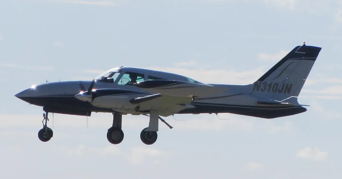


In this document
Aircraft Specifications
This section outlines the key specifications of the Cessna 310F, including dimensions, weight limits, and engine details. The aircraft features a wingspan of 38 ft 4 in, a length of 28 ft 9 in, and a height of 8 ft 11 in. The maximum takeoff weight is 5,200 lbs, with an empty weight of approximately 3,200 lbs.
Performance Data
The performance section provides critical data such as takeoff and landing distances, stall speeds, and fuel consumption rates. For the Cessna 310F, the takeoff distance over a 50 ft obstacle is approximately 2,500 ft, while the landing distance over a 50 ft obstacle is about 2,200 ft.
Weight and Balance
This section details the weight and balance calculations necessary for safe flight operations. The basic empty weight of the Cessna 310F is 3,200 lbs, with a maximum ramp weight of 5,200 lbs. The useful load is 2,000 lbs, and the baggage allowance is 200 lbs.
Emergency Procedures
Emergency procedures are outlined to prepare pilots for various in-flight emergencies. This includes engine failure, electrical failure, and other critical situations, providing step-by-step instructions for safe handling.
V-Speeds
The V-speed section lists important airspeeds for the Cessna 310F, including Vso (stalling speed in landing configuration) at 60 KIAS, Vx (best angle of climb speed) at 74 KIAS, and Vy (best rate of climb speed) at 88 KIAS.
Safety notes
- Always perform a weight and balance calculation before flight.
- Be aware of stall speeds during various configurations.
Full document text
THERE ARE MORE CESSNAS FLYING THAN ANY OTHER MAKE ACROSS NATIONS CESSNA "TAKE YOUR CESSNA HOME FOR SERVICE AT THE SIGN OF THE CESSNA SHIELD" 1965 CESSNA sna. AROUND THE WORLD CESSNA AIRCRAFT COMPANY WICHITA, KANSAS MODEL 310 J OWNER'S MANUAL WORLD'S LARGEST PRODUCER OF GENERAL AVIATION AIRCRAFT SINCE 1956 PERFORMANCE AND SPECIFICATIONS. GROSS WEIGHT . SPEED: BEST POWER MIXTURE Maximum at Sea Level Maximum Recommended Cruise 75% Power at 6500 ft. RANGE: NORMAL LEAN MIXTURE Maximum Recommended Cruise 75% Power at 6500 ft. 780 mi. 100 Gallons, No Reserve 3.5 hrs. 221 mph. 1015 mi. 75% Power at 6500 ft. 130 Gallons, No Reserve 221 mph. Maximum Range at 10,000 ft. 100 Gallons, No Reserve 980 mi. 5.5 hrs. 180 mph. 130 Gallons, No Reserve 1270 mi. 7.1 hrs. RATE OF CLIMB AT SEA LEVEL: Twin Engine Single Engine SERVICE CEILING: Twin Engine Single Engine 7500 ft. TAKE-OFF PERFORMANCE: Take-off Speed 85 MPH (Vmc) Ground Run 1385 ft. Total Distance over 50 ft. obstacle 1640 ft. LANDING PERFORMANCE: Approach Speed (100 MPH) Landing Roll 960 ft. 1540 ft. Total Distance over 50 ft. obstacle EMPTY WEIGHT (Approximate) BAGGAGE ALLOWANCE: WING LOADING: POWER LOADING: FUEL CAPACITY: Total Standard Optional Auxiliary Tanks. Optional Auxiliary and Wing Locker Tanks OIL CAPACITY: Total POWER: Two Continental 6-Cylinders, Fuel Injection IO-470-U Engines, 260 rated Horsepower at 2625 rpm PROPELLER: Constant Speed, Full Feathering, Dia. * Single-Engine Service Ceiling increases 425 feet each 30 minutes of flight. D850-13-RAND-200-4/75 CONGRATULATIONS. 5100 lbs. 238 mph 223 mph 4.6 hrs. 180 mph. 1590 fpm. 360 fpm. 20,300 ft. 3094 lbs. 600 lbs. 29.1 lbs./sq. ft. 9.8 lbs./hp. 102 gal. 133 gal. 173 gal. 6 gal. 81 inches Welcome to the ranks of Cessna owners! Your Cessna Model 310 has been designed and constructed to give you the most in performance, econ- omy, and comfort. It is our desire that you will find flying it, either for business or pleasure, a pleasant and profitable experience. This Owner's Manual has been prepared as a guide to help you get the most pleasure and utility from your Model 310. It contains information about your Cessna's equipment, operating procedures, and performance; and suggestions for its servicing and care. We urge you to read it from cover to cover, and to refer to it frequently. Our interest in your flying pleasure has not ceased with your purchase of a Cessna. World-wide, the Cessna Dealer Organization backed by the Cessna Service Department stands ready to serve you. The following services are offered by most Cessna Dealers: FACTORY TRAINED PERSONNEL to provide you with courteous expert service. FACTORY APPROVED SERVICE EQUIPMENT to provide you with the most efficient and accurate workmanship possible. A STOCK OF GENUINE CESSNA SERVICE PARTS on hand when you need them. THE LATEST AUTHORITATIVE INFORMATION FOR SERV- ICING CESSNA AIRPLANES, since Cessna Dealers have all of the Service Manuals and Parts Catalogs, kept current by Service Letters and Service News Letters published by Cessna Aircraft Company. We urge all Cessna owners to use the Cessna Dealer Organization to the fullest. A current Cessna Dealer Directory accompanies your new airplane. The directory is revised frequently, and a current copy can be obtained from your Cessna Dealer. Make your Directory one of your cross-coun- try flight planning aids; a warm welcome awaits you at every Cessna Dealer. ii -29'-6" 28'-10"- 6'-6 7/8" 9'-11 1/4"* TABLE OF CONTENTS 7-6 5/8" 310J Page 9-6 3/4"- 17.0' SECTION I - OPERATING CHECKLIST 1-1 PRINCIPAL DIMENSIONS SECTION || DESCRIPTION AND OPERATING DETAILS 2-1 *Maximum height of airplane with nose gear depressed is 10'-8 3/4" if rotating beacon is installed, add 3" to maximum height. 81" 36'-11". -12'-0" 310J SECTION III EMERGENCY PROCEDURES. 3-1 10'-0" SECTION IV - OPERATING LIMITATIONS.. .4-1 SECTION V - CARE OF THE AIR PLANE. OWNER FOLLOW-UP SYSTEM 5-1 5-4 SECTION VI - OPERATIONAL DATA 6-1 SECTION VII OPTIONAL SYSTEMS. ALPHABETICAL INDEX. .7-1 Index - 1 iii SECTION I OPERATING CHECKLIST 1. a. Turn on battery switch. Check fuel quantity gages, check operation of stall warning trans- mitter tab and horn by raising tab on left wing, and check main tank transfer pumps for opera- tion (listen for audible clicking emanating from main tanks). Turn battery switch OFF. b. Check landing gear switch DOWN. c. Check magneto switches OFF. d. Check left fuel selector in LEFT MAIN posi- tion and right fuel selector in RIGHT MAIN position (feel for detent). Check oxygen knob - PULL ON. e. f. Check oxygen pressure. g. Remove control lock. 2. a. Open baggage door and check that oxygen masks and hoses are available. b. Close baggage door and check for security. i. J. EXTERIOR INSPECTION NOTE Check general aircraft condition during walk-around inspection. If night flight is planned, check operation of all lights; make sure a flashlight is available. Check wing locker fuel tank vent for obstructions, if installed. Check wing locker fuel tank cap for security, if installed. k. On first flight of the day and after each refuel- ing, drain small amount of fuel from quick- drain valve in the auxiliary tank and wing locker fuel transfer line, if installed. 1. Check battery drain and battery compartment cover panel for security (left side only). m. Remove wing tie-down. 4. a. Check oil level. (Do not operate on less than 9 quarts. Fill to 10 quart level for flights of less than 3 hours. Fill to capacity for extended flights.) Check dip stick for security and eng- ine compartment for general condition. b. Check oil filler cap for security through oil filler access door. 310J One of the first steps in obtaining the utmost performance, service, and flying enjoyment from your Cessna Model 310 is to familiarize yourself with your airplane's equipment, systems, and controls. This can best be done by reviewing this equipment while sitting in the airplane. Those items
Show full textShow less
whose function and operation are not obvious are covered in Section II. Section I lists, in Pilot's Checklist form the steps necessary to operate your airplane efficiently and safely. It covers briefly all the points that you should know concerning the information you need for a typical flight. The flight and operational characteristics of your airplane are normal in all respects. All controls respond in the normal way within the entire range of operation. All airspeeds mentioned in Sections I and II are indi- cated airspeeds. Corresponding calibrated speeds may be obtained from the Airspeed Correction Table, Figure 6-1. MAKE AN EXTERIOR INSPECTION IN ACCORDANCE WITH FIGURE 1-1. BEFORE STARTING THE ENGINES. (1) c. c. Check static pressure source holes for ob- struction (both sides of fuselage). Check main landing gear strut and tire inflation. Check gear doors for security. (2) (3) d. d. Remove control surface locks, if installed. e. Remove tie-down. On first flight of day and after each refueling, drain about two ounces of fuel from fuel strainer to clear of any water and sediment. (4) Seats and Safety Belts Brakes -- Test and set. Landing Gear Switch Battery Switch -- - Adjust and lock. Check DOWN. 11 ON. e. Check wing locker door for security. f. Check propeller and spinner for nicks, cracks and security and propeller for oil leaks. Check cowl access doors for security. NOTE 5. a. Check left nose access panel for security. 3. a. b. On first flight of the day and after each refuel- ing, drain small amount of fuel from quick- drain valve in the wing locker fuel tank, if installed. c. Remove control surface lock, if installed. d. Check sniffle valve opening for obstruction. e. Check main fuel tank vent for obstructions (especially water and ice accumulation in the tank vent shield during cold weather operation). Check main fuel tank cap for security. On first flight of the day and after each refuel- ing, drain small amount of fuel from quick- drain valve in the main tank. f. g. h. Check auxiliary fuel tank cap for security. b. Check nose gear strut and tire inflation; check nose gear doors for security. d. Check right nose access panel for security. Remove pitot tube cover, if installed, and c. Remove tie-down, if installed. e. f. check pitot tube opening for obstructions. Check heater inlet for obstructions. 6. a. Same as 4. 7. a. Same as 3 except in reverse order. When using an external power source, do not turn on the battery switch until external power is disconnected, to avoid a weak battery draining off part of the current being supplied by the external source. (5) Generator Switches -- ON. NOTE iv Figure 1-1. If 50 ampere generators are installed, turn on one at a time as the engines are started. 1-1 SECTIONI OPERATING CHECKLIST. (9) Oil Temperature -- (6) 33 (7) Fuel Selectors Landing Gear Lights Press to test (check iris - open). Left Engine (10) Right Engine LEFT MAIN (feel for detent). RIGHT MAIN (feel for detent). (11) Check green arc. Trim Controls Check. -- Cabin Door and Windows Closed and locked. (12) (8) Trim Controls Set. (13) Flight Instruments and Radios Set. Auxiliary Fuel Pumps -- -- ON. -- (9) Altimeter and Clock -- Set. (10) Turn All Radio Switches -- OFF. 33340 STARTING ENGINES (Left Engine First). 1- Propeller TAKEOFF. NORMAL TAKEOFF. (1) Mixture Full Rich. (2) -- High RPM. (3) Throttle - Open 1 inch. (4) Magneto Switches -- ON. (5) Start Engine. (a) Primer Switch Left Engine -- LEFT. (b) Starter Button -- Right Engine RIGHT. Press. -- NOTE (1) Wing Flaps - 0°. (2) Mixtures Lean for field elevation. NOTE If the primer switch is actuated longer than two or three seconds with the engines inoperative on the ground, damage may be incurred to the engine and/or airplane due to excessive fuel accumulation. Leaning during the takeoff roll is normally not necessary; however, should maximum takeoff or subsequent engine- out performance be desired, fuel flow should be adjusted to match field elevation. (3) (4) ི� Induction Air Power -- Check COLD. Full throttle and 2625 RPM. NOTE During very hot weather, caution should be exercised to prevent overpriming the engines. If there is an indica- tion of vapor in the fuel system (fluctuating fuel flow) with engines running, place the auxiliary fuel pump switch to the LOW position until the system is purged. Apply full throttle smoothly to avoid propeller surging. (5) Maintain Level Attitude. (6) Elevator Control Raise nose wheel at 90 MPH. (7) Break Ground at 102 MPH. BEFORE TAKEOFF. (1) Flight Controls Check (free and correct). (2) Throttle Settings 1700 RPM. (3) Engine Instruments -- (4) Generators Check. (5) Magnetos -- Check. ―― Check (50 RPM maximum differential between (6) (7) (8) Vacuum Source of mercury). -- Check source and suction (4.75 to 5.25 inches magnetos). Induction Air Heat Source Check by noting RPM and manifold pressure drop. Propellers Check feathering to 1200 RPM; return to high RPM (full forward position). Brakes Apply momentarily. -- -- Climb Speed 124 MPH (best twin-engine rate-of-climb speed). (Set up climb speed as shown in "NORMAL CLIMB" para- graph.) Auxiliary Fuel Pumps MAXIMUM PERFORMANCE TAKEOFF. (1) Wing Flaps - 15°. (2) (4) Power Full throttle and 2625 RPM. -- Maintain Level Attitude. Elevator Control Lift nose wheel at 77 MPH. -- (8) (9) Landing Gear Retract. (10) (11) OFF. ཌསེ་ེ 1-2 1-3 SECTION I Break Ground at 87 MPH Hold speed until all obstacles are Apply momentarily. (5) cleared. (6) Brakes -- (7) Landing Gear -- (8) Flaps (9) -- Retract. Retract (after obstacles are cleared). Auxiliary Fuel Pumps OFF. CLIMB. NORMAL CLIMB. (1) Airspeed 130 160 MPH. (2) (3) -- Power 24 inches Hg. and 2450 RPM. Mixtures - Adjust to climb fuel flow. MAXIMUM PERFORMANCE CLIMB. ཌསེ་ོ 124 MPH at sea level; 122 MPH at 10,000 feet. Full throttle and 2625 RPM. (1) (2) (3) Airspeed- Power Mixtures -- · Adjust for altitude and power. LETDOWN. (1) Power As required. (2) Mixtures Full Rich. OPERATING CHECKLIST BEFORE LANDING. - Fuel Selectors -- Left Engine LEFT MAIN (feel for detent). Right Engine - RIGHT MAIN (feel for detent). Full Rich. -- Auxiliary Fuel Pumps Induction Air (1) (2) Mixtures -- (3) (4) (5) (6) (7) (8) (9) ུ ⊕ བུ ⊕ གྱ ➢ ཕྱེ -- ON. Check COLD. Propellers High RPM. -- Wing Flaps 15° below 160 MPH; 15° to 35° below 140 MPH. Landing Gear Extend below 140 MPH. -- Landing Gear Position Indicator Light Approach --102 MPH. -- Check green light on. LANDING. (1) Touchdown Main wheels first. CRUISING. (1) Cruise Power 23-24 inches Hg. and 2100 (2) -- (3) 2450 RPM. Mixtures Lean for desired cruise fuel flow as determined from your Cessna 310 Power Computer. Fuel Selectors - MAIN TANKS for first 60 minutes. After 60 minutes of flight, if auxiliary fuel tanks are installed, fuel selectors may then be placed in AUXILIARY position, and feel for detent. (a) - MAIN If wing locker tanks are installed, fuel selectors TANKS or, after wing locker tanks are transferred and main tank quantity is less than 30 gallons each IARY TANKS. - AUXIL- -- Lower nose wheel gently. (2) Landing Roll Braking As required. (3) AFTER LANDING. (1) Auxiliary Fuel Pumps (2) Wing Flaps Retract. SECURE AIRPLANE. OFF. (1) Mixtures IDLE CUT-OFF. Magneto Switches OFF, after engines stop. (2) (3) All Switches -- OFF. (4) Brakes -- Set. Control Lock -- Install. 33 (5) (4) 1-4 NOTE Turn auxiliary fuel pumps to LOW and mixtures to FULL RICH when switching tanks. Trim Tabs Adjust. SELECT as re- If wing locker tanks are installed, Crossfeed -- quired to maintain fuel balance after wing locker tank fuel transfer. Cabin Door -- Close and rotate exterior door handle clockwise to latch cabin door. NOTE To securely latch the cabin door from the outside, the exterior door handle must be rotated clockwise to its stop. 1-5 SECTION I Notes 310J SECTION II DESCRIPTION AND OPERATING DETAILS The following paragraphs supply a general description of some sys- tems and equipment in the airplane. This section also covers, in some- what greater detail, some of the items listed in Checklist form in Section I. Only those items of the Checklist requiring further explanation will be covered here. FUEL SYSTEM Fuel for each engine is supplied by a main tank (50 gallons useable) on each wing tip. Each engine has its own complete fuel system; two sys- tems are interconnected only by a cross feed for emergency use. Vapor and excess fuel from the engines are returned to the main fuel tanks. Submerged electric auxiliary pumps in the main fuel tanks supply fuel for priming and starting, and for engine operation as a backup system to the engine driven pumps. Refer to Figure 2-1 for fuel system schematic. AUXILIARY FUEL PUMP SWITCHES The LOW position runs the pumps at low speed, providing 9 PSI pres- sure for purging. The ON position also runs the pumps at low speed, as long as the engine-driven pumps are functioning. With the switch posi- tioned to ON, however, if an engine-driven pump should fail, the auxili- ary pump on that side will switch to high speed automatically providing sufficient fuel for all engine operations including emergency take-off. When oil pressure (20 PSI and above) isn't available to an engine, its auxiliary fuel pump will not run. A continuous duty tip tank transfer pump is installed in each main tip tank. The pumps assure availability of all tip tank fuel to the engine sup- ply line during high angles of descent. Each pump is electrically protect- ed by the respective landing light circuit breaker. When the right-hand landing light is not installed, the right-hand pump will either have a sepa- rate circuit breaker or be combined with an existing circuit breaker. During preflight inspection these pumps can be checked for operation by listening for a pulsing sound emanating from the aft tip tank fairings with the battery switch in the on position. FUEL STRAINER AND TANK SUMP DRAINS Refer to Servicing Procedures Page 5-6. 2-1 1-6 SECTION II SCHEMATIC FUEL SYSTEM FUEL TRANSFER LIGHTS TIP TANK TRANSFER PUMP PRESSURE SWITCH- WING LOCKER. -PRESSURE SWITCH FUEL TRANSFER PUMPS VENT VENT LEFT LEFT AUX. FUEL -OPTIONAL WING- LOCKER FUEL TANK- FUEL TANK TANK (OPT) RIGHT AUX. FUEL TANK (OPT) TO HEATER AUX. PUMP LEFT ENGINE FUEL PUMP THROTTLE MIXTURE CONTROL TO CYLINDERS FUEL INJECTION NOZZLE SELECTOR VALVE STRAINER STRAINER SELECTOR VALVE LEFT ENGINE FUEL CONTROL UNIT RIGHT ENGINE FUEL CONTROL UNIT LEFT ENGINE FUEL MANIFOLD RIGHT ENGINE FUEL MANIFOLD DUAL FUEL FLOW GAGE CODE FUEL SUPPLY VAPOR RETURN MECHANICAL ACTUATION CHECK VALVE 2-2 Figure 2-1. RIGHT FUEL TANK AUX. PUMP RIGHT ENGINE FUEL PUMP TIP TANK TRANSFER PUMP THROTTLE MIXTURE CONTROL TO CYLINDERS FUEL INJECTION NOZZLE DESCRIPTION AND OPERATING DETAILS ELECTRICAL SYSTEM Electrical energy is supplied by a 28-volt, negative-ground, direct- current system powered by a 25-ampere engine-driven generator on each engine. Two 12-volt batteries, connected in series, are located in the left wing just outboard of the engine nacelle. An external power recep- tacle is installed in the left wing under the batteries. The receptacle ac- cepts a standard power plug. BATTERY AND GENERATOR SWITCHES Separate battery and generator switches provide a means of checking for a malfunctioning generator circuit, and permit such a circuit to be cutoff. If a generator circuit fails or malfunctions, or when one engine is not running the switch for that generator should be turned off. Opera- tion should be continued on the functioning generator, using only neces- sary electrical equipment. If both generator circuits should malfunction, equipment can be operated at short intervals and for a limited amount of time on the battery alone. CIRCUIT BREAKERS All of the electrical systems in the airplane are protected by "push- to-reset" type circuit breakers. When an overload occurs, the breaker pops out to indicate which circuit is overloaded. LANDING GEAR SYSTEM The electrically operated landing gear is fully-retractable and incor- porates a steerable nosewheel. To help prevent accidental retraction, an automatic safety switch on the LEFT shock strut prevents retraction as long as the weight of the airplane is sufficient to compress the strut. The landing gear is operated by a switch, which is identified by a wheel- shaped knob. The switch positions are UP, OFF, and DOWN. To oper- ate the gear, pull out on the switch knob and move to desired position. LANDING GEAR POSITION LIGHTS Two landing gear position lights are mounted one above the other below the landing gear switch. The lights are push-to-test type with dimming shutters. Brightness can be controlled by rotating the shutters. When illuminated the red light indicates the gear is fully retracted, and the green light illuminates when the landing gear is fully extended and locked. When neither light is on, the landing gear is in an intermediate position. 2-3 SECTION II DESCRIPTION AND OPERATING DETAILS HEATER USED FOR VENTILATION. LANDING GEAR WARNING HORN. The landing gear warning horn is controlled by the throttles, and will sound an intermittent note if either throttle is retarded below approxi- mately 12 inches Hg. manifold pressure with the gear up. The warning horn is also connected to the UP position of the landing gear switch, and will sound if the switch is placed in the UP position while the airplane is on the ground. LANDING GEAR HANDCRANK. A handcrank for manually lowering the landing gear is located just be- low the right front edge of the pilot's seat. NOTE The handcrank handle must be stowed in its clip before the landing gear will operate electrically. When the handle is placed in operating position, it disengages the landing gear motor from the actuator gear. The procedure for manually lowering the landing gear is given in Section III. HEATER SYSTEM. HEATER OPERATION FOR HEATING AND DEFROSTING. (1) Battery Switch -- ON. (2) (3) Cabin Air Knobs OPEN. Defrost Knob (4) (5) Cabin Heat Switch (6) -Adjust as desired (if defrosting is desired). Temperature Control Knob MAX. -- HEAT. Temperature Control and Heat Registers As desired. NOTE -- If warm air is not felt coming out of the registers within one minute, return cabin heat switch to OFF, check cir- cuit breaker and try another start. If heater still does not start, no further starting attempt should be made. (1) Battery Switch -- ON. (2) Cabin Air Knobs -- (3) Cabin Heat Switch OPEN. FAN. (4) Heat Registers -- As desired. OVERHEAT WARNING LIGHT. An amber overheat warning light is provided and is labeled HEATER- OVERHEAT, T & B TEST. When illuminated, the light indicates that the heater overheat switch has been actuated and indicates the temperature of the air in the heater exceeds 325°F. Once the heater overheat switch has been actuated, the heater turns off and cannot be restarted until the over- heat switch is reset. Prior to having the overheat switch reset, the heat- er should be inspected thoroughly to determine the reason for the mal- function. STATIC-PRESSURE ALTERNATE-SOURCE VALVE. A static-pressure alternate-source valve, installed in the static sys- tem, directly below the parking brake handle, supplies an alternate static source should the external source malfunction. This valve also perinits draining condensate from the static lines. When open, this valve vents to the static pressure in the cabin and since this is relatively low, the airspeed indicator and the altimeter will show slightly higher readings than normal. Therefore, the alternate static source should be used pri- marily as a drain valve to restore the original system. If the alternate static source must be used for instrument operation, compensation should be made in the indicated airspeeds and altitudes. In landing with the alternate source valve open and the pilot's storm window closed, fly at an indicated airspeed 10 MPH faster and an altitude 30 feet higher than normal. With the static source valve open and the pilot's storm window open, make these allowances, 26 MPH and 160 feet. STARTING ENGINES. Although either engine may be started first and the procedure is ident- ical for both, the left engine is normally started first. The cable from 2-4 2-5 SECTION It the battery to this engine is much shorter, which permits more electrical power to be delivered to the starter. If batteries are low, the left engine should start more readily. When using an external power source, it is recommended to start the airplane with the battery switch OFF. The continuous flow fuel injection system will start spraying fuel in the engine intake ports as soon as the primer switch is pressed on and the throttle and mixture controls are opened. To avoid flooding, be sure you are ready to crank the engine as soon as a steady fuel flow is obtained. In hot weather with a hot engine, a fluctuating fuel flow slightly lower than normal may be obtained. This is an indication of vaporized fuel and the starter should not be energized until a steady fuel flow indication is obtained. DESCRIPTION AND OPERATING DETAILS for sharp turns during taxiing. Steering may be aided thru use of differ- ential power and differential braking on the main wheels. These aids are listed in the preferred order of use. BEFORE TAKEOFF (Use The Pilot's Checklist). Full throttle checks on the ground are not recommended unless there is good reason to suspect that the engines are not turning-up properly. Do not run-up the engines over loose gravel or cinders because of pos- sible stone damage or abrasion to the propeller tips. If the ignition system check produces an engine speed drop in excess of 125 RPM or if the drop in RPM between left and right magneto differs by more than 50 RPM, continue warm-up a minute or two longer, before re- checking system. If there is doubt concerning operation of the ignition system, checks at higher engine speed will usually confirm if a deficiency exists. NOTE Caution should be exercised to prevent overpriming the engine in hot weather. Engine mis-starts characterized by weak, intermittent explosions fol- lowed by puffs of black smoke from the exhaust are the result of flooding or overpriming. This situation is more apt to develope in hot weather, or when the engines are hot. If it occurs, repeat the starting procedure with the throttle open approximately 1/2, the mixture in idle cut-off and the primer switch off. As the engine fires, move the mixture control to full rich and close the throttle to idle. If an engine is underprimed, as may occur in cold weather with a cold engine, repeat the starting procedure after holding the primer switch on for 10 to 15 seconds until the engine fires. If cranking longer than 30 seconds is required, allow starter motor to cool for five minutes before cranking again, since excessive heat may damage the armature windings. TAXIING. A steerable nosewheel interconnected with the rudder system provides positive control up to 15 left or right, and free turning from 15° to 55° 2-6 TAKEOFF. Observe full-power engine operation early in the takeoff run. Signs of rough engine operation, unequal power between engines, or sluggish engine acceleration are good cause for discontinuing the takeoff. For maximum engine power, the mixture should be adjusted during the initial acceleration for smooth engine operation at the field elevation. The engine acceleration is increased significantly with fuel leaning above 3000 feet and this procedure always should be employed for field eleva- tions greater than 5000 feet above sea level. Full throttle operation is recommended on takeoff since it is important that a speed well above minimum single-engine control speed (87 MPH) be reached as rapidly as possible. After takeoff it is important to maintain the recommended safe single- engine speed (102 MPH). After obstruction height is reached, the gear retracted, power may be reduced and climb speeds may be established as described in Section I. On long runways, the landing gear should be retracted at the point over the runway where a wheels-down forced landing on that runway would be- 2-7 SECTION II DESCRIPTION AND OPERATING DETAILS come impractical. However, on short runways, it is preferable to re- tract the landing gear after minimum control speed (87 MPH) is obtained. Performance data for both normal and obstacle clearance takeoff are presented in Section VI. CLIMB. To save time and fuel for the over-all trip, it is recommended that the normal cruising climb be conducted at 130 to 160 MPH using approx- imately 75% power (24 inches Hg. manifold pressure, 2450 RPM). The mixture should be leaned in this type of climb to give the desired fuel flow in the climb dial range which is approximately best power mix- ture. If it is necessary to climb rapidly to clear mountains or reach favor- able winds at high altitudes, the best rate-of-climb speed should be used with maximum power. This speed varies from 124 MPH at sea level to 122 MPH at 10,000 feet. During maximum performance climbs, the mixture should be leaned to the appropriate altitude markings on the fuel flow gage. If an obstruction ahead requires a steep climb angle, the airplane should be flown at the best angle-of-climb speed with flaps up and max- imum power. This speed varies from 95 MPH at sea level to 111 MPH at 15,000 feet. CRUISE. Tabulated cruising information for normal cruising power and altitudes is presented in Section VI. Normal cruising requires between 60% and 70% power. The manifold pressure and RPM settings required to obtain these powers at various altitudes and outside air temperature can be determined with your Cessna Model 310 Power Computer. The maximum cruising power of approxi- mately 75% (24 inches Hg. manifold pressure, 2450 RPM) may be used if desired. Various percent powers can be obtained with a number of combinations of manifold pressures, engine speeds, altitudes, and outside air tempera- 2-8 tures. However, at full throttle and constant engine speed, a specific power can be obtained at only one altitude for each given air temperature. To achieve the level flight performance shown in the cruising charts in Section VI, lean the mixtures to give the fuel flows shown. This will yield airspeeds slightly below (approximately one to two MPH) those available at best power mixture. Should maximum speed be desirable, the mixture should be adjusted to approximately one gph higher than that indicated by the range charts on the Cessna Model 310 Power Computer. This will yield approximately best power mixture with a resulting airspeed of one to two MPH greater and a fuel flow approximately one gallon per hour greater than those listed in Section VI. For a given throttle setting, select the lowest engine speed in the green arc range that will give smooth engine operation without evidence of la- boring. For best propeller synchronization, the final adjustment of the prop- eller pitch levers should be made in a DECREASE RPM direction. The induction air system employed on these engines is considered to be non-icing. However, induction air heat is incorporated to assure sat- isfactory operation in the unlikely event that unusual atmospheric condit- ions should cause induction system icing. The induction air handles should be left in the full COLD position for all normal operations. Should induction system icing be encountered, the induction air handles should be pulled to the full heat position. If this condition occurs the engine mix- ture control should be leaned for smooth engine operation. STALL. The stall characteristics of this airplane are conventional and aural warnings are provided by the stall warning horn between 5 and 10 MPH above the stall in all configurations. The stall is also preceded by a mild aerodynamic buffet which increases in intensity as the stall is ap- proached. The power-on stall occurs at a very steep angle either with or without flaps, and it is difficult to inadvertently stall the airplane during normal maneuvering. Power-off stall speeds at maximum gross weight are presented in Figure 6-2 as both indicated and calibrated airspeeds. 2-9 SECTION II DESCRIPTION AND OPERATING DETAILS SPINS. Intentional spins are not permitted in this airplane. Should a spin oc- cur, however, the following recovery procedure should be employed: Apply full rudder opposing the direction of rotation. Approximately 1/2 turn after applying rudder, push control wheel forward briskly. (1) Cut power on both engines. (2) (3) (4) (5) To expedite recovery, add power to the engine toward the inside of the direction of turn. Pull out of dive with smooth, steady control pressure. COLD WEATHER OPERATION. Whenever possible, external preheat should be utilized in cold weather. The use of preheat materially reduces the severity of conditions imposed on both the engines and electrical systems. It is the preferred or best method of starting engines in extremely cold weather. Preheat will thaw the oil trapped in the oil coolers and optional oil filters which will prob- ably be congealed prior to starting in very cold weather. If preheat is not available, external power should be used for starting because of the higher cranking power required, and the decreased battery output at low temperatures. The starting procedure is normal, however, if the engines do not start immediately it may be necessary to position the primer switch to LEFT or RIGHT for 10 to 15 seconds. After a suitable warm-up period (2 to 5 minutes at 1000 RPM if preheat is not used) accelerate the engines several times to a higher RPM. The propellers should be operated through several complete cycles to warm the governors and propeller hubs. If the engines accelerate smoothly, the oil pressure remains normal and steady, the airplane is ready for take- off. During cruise the propellers should be exercised at half-hour intervals to flush the cold oil from the governors and propeller hubs. Electrical equipment should be managed to assure adequate generator charging throughout the flight, since cold weather adversely affects battery capa- city. During letdown, watch engine temperatures closely and carry sufficient power to maintain them above operating minimums. 2-10 The pitot and stall warning heater switch should be turned ON at least 5 minutes before entering a potential icing condition so that these units will be warm enough to prevent formation of ice. Preventing ice is pre- ferable to attempting its removal once it has formed. Refer to Section VII for Optional Cold Weather Equipment. 2-11 SECTION II Notes 2-12 310J SECTION !!! EMERGENCY PROCEDURES ENGINE-OUT PROCEDURES. ENGINE-OUT ON TAKEOFF. (With Sufficient Runway Remaining). (1) Cut power and decelerate to a stop. NOTE The airplane can be accelerated from a standing start to 102 MPH on the ground, then decelerated to a stop with heavy braking within 3046 feet of the starting point of the takeoff run at sea level, and within 3863 feet of the starting point at 5000 feet altitude (zero wind, hard surface runway, standard conditions, full gross weight). ENGINE-OUT AFTER TAKEOFF-ABOVE 102 MPH. (Without Sufficient Runway Ahead). (1) Throttles -- Full Forward. Propellers - High RPM. (3) Landing Gear -- UP. ུ་ེཌཱུཕི©C⊕ Determine Inoperative Engine (idle engine same side as idle foot). Propeller FEATHER (inoperative engine). Climb Out at 102 MPH. Accelerate to 118 MPH after Obstacle is Cleared. (4) (5) (6) (8) Wing Flaps -- (9) (a) UP (if extended) in small increments. Secure Inoperative Engine as Follows: Auxiliary Fuel Pump OFF. (b) Mixture IDLE CUT-OFF. 39000 (c) Magneto Switches OFF. (d) Generator Switch OFF. (e) Fuel Selector Valve OFF. 3-1 SECTION III EMERGENCY PROCEDURES SUPPLEMENTARY INFORMATION CONCERNING ENGINE-OUT DURING TAKEOFF. The most critical time for an engine-out condition in a twin-engine airplane is during a two or three second period late in the takeoff run while the airplane is accelerating to a safe engine-out speed. A detailed knowledge of recommended single-engine airspeeds in the table below is essential for safe operation of this airplane. These speeds should be memorized for instant recollection in an emer- gency, and it is worthwhile to review them mentally, prior to every take- off. The following paragraphs present a detailed discussion of the prob- lems associated with engine failures during takeoff. SINGLE-ENGINE AIRSPEED NOMENCLATURE IAS-MPH 1. Minimum control speed 87 2. Recommended safe single-engine speed 3. Best angle-of-climb speed 102 107 4. Best rate-of-climb speed (flaps up) 118 MINIMUM CONTROL SPEED. The twin-engine airplane must reach the minimum control speed (87 MPH) before full control deflections can count- eract the adverse rolling and yawing tendencies associated with one engine inoperative and full power operation on the other engine. RECOMMENDED SAFE SINGLE-ENGINE SPEED. Although the airplane is controllable at the minimum control speed, the airplane performance is so far below optimum that continued flight near the ground is improb- able. A more suitable recommended safe single-engine speed is 102 MPH since at this speed altitude can be maintained more easily while the land- ing gear is being retracted and the propeller is being feathered. BEST ANGLE-OF-CLIMB SPEED. The best angle-of-climb speed for single-engine operation becomes important when there are obstacles ahead on takeoff, because once the best single-engine angle-of-climb speed is reached, altitude becomes more important than airspeed until the obstacle is cleared. The best single-engine angle-of-climb speed is approximately 107 MPH with flaps up. For convenience, a speed of 102 MPH may be used for any flap setting between 0 -15°. BEST RATE-OF-CLIMB SPEED (FLAPS UP). The best rate-of-climb speed for single-engine operation becomes important when there are no obstacles ahead on takeoff, or when it is difficult to maintain or gain alti- tude in single-engine emergencies. The best single-engine rate-of-climb speed is 118 MPH with flaps up, at sea level. 3-2 The variation of flaps-up best rate-of-climb speed with altitude is shown in Section VI. For best climb performance, the wings should be banked 5° toward the operative engine. Upon engine failure after reaching 102 MPH on takeoff, the twin-engine pilot has a significant advantage over a single-engine pilot, for he has the choice of stopping or continuing the takeoff. This would be similar to the choice facing a single-engine pilot who has suddenly lost slightly more than half of his takeoff power. In this situation, the single-engine pilot would be extremely reluctant to continue the takeoff if he had to climb over obstructions. However, if the failure occurred at an altitude as high or higher than surrounding obstructions, he would feel free to man- euver for a landing back at the airport. Fortunately the airplane accelerates through this "area of decision" in just a few seconds. However, to make an intelligent decision in this type of an emergency, one must consider the field length, obstruction height, field elevation, air temperature, headwind, and the gross weight. The flight paths illustrated in the figure below indicate that the "area of decision" is bounded by: (1) the point at which 102 MPH is reached and (2) the point where the obstruction altitude is reached. An engine failure in this area requires an immediate decision. Beyond this area, the air- plane, within the limitations of single-engine climb performance shown in Section VI, may be maneuvered to a landing back at the airport. SINGLE ENGINE TAKE OFF 102 MPH AREA OF DECISION ACCELERATE STOP DISTANCE- TOTAL TAKEOFF DISTANCE OVER OBSTACLE- At sea level, with zero wind and 5100 pounds gross weight, the distance to accelerate to 102 MPH and stop is 3046 feet, while the total unobstruc- ted area required to takeoff and climb over a 50-foot obstacle after an en- gine failure at 102 MPH is 3720 feet. This total distance over an obstacle can be reduced slightly under more favorable conditions of gross weight, headwind, or obstruction height. However, it is recommended that in most cases it would be better to discontinue the takeoff, since any slight mismanagement of the single-engine procedure would more than offset the small distance advantage offered by continuing the takeoff. The ad- vantage of discontinuing the takeoff is even more obvious at higher alti- 3-3 SECTION IIE EMERGENCY PROCEDURES tudes where the corresponding distances are 3411 and 4970 respectively, at 2500 feet. Still higher field elevations will cause the engine-out takeoff distance to lengthen disproportionately until an altitude is reached where a successful takeoff is improbable unless the airspeed and height above the runway at engine failure are great enough to allow a slight deceleration and altitude loss while the airplane is being prepared for a single-engine climb. During single-engine takeoff procedures over an obstacle, only one condition presents any appreciable advantage, and this is headwind. A decrease of approximately 10% in ground distance required to clear a 50- foot obstacle can be gained for each 10 MPH of headwind. Excessive speed above best single-engine climb speed at engine failure is not nearly as advantageous as one might expect since deceleration is rapid and ground distance is used up quickly at higher speeds while the airplane is being cleaned up for climb. However, the extra speed is important for controllability. The following facts should be used as a guide at the time of engine fail- ure: (1) discontinuing a takeoff upon engine failure is advisable under most circumstances; (2) altitude is more valuable to safety after takeoff than is airspeed in excess of the best single-engine climb speed since ex- cess airspeed is lost much more rapidly than is altitude; (3) climb or con- tinued level flight at moderate altitude is improbable with the landing gear extended and the propeller windmilling; (4) in no case should the airspeed be allowed to fall below the engine-out best angle-of-climb speed, even though altitude is lost, since this speed will always provide a better chance of climb, or a smaller altitude loss, than any lesser speed. The engine-out best rate-of-climb speed will provide the best chance of climb or the least altitude loss, and is preferable unless there are obstructions which make a steep climb necessary. Engine-out procedures should be practiced in anticipation of an emer- gency. This practice should be conducted at a safe altitude, with full pow- er operation on both engines, and should be started at a safe speed of at least 120 MPH. As recovery ability is gained with practice, the starting speed may be lowered in small increments until the feel of the airplane in emergency conditions is well known. Practice should be continued until: (1) an instinctive corrective reaction is developed, and the corrective pro- cedure is automatic; and (2), airspeed, altitude, and heading can be main- tained easily while the airplane is being prepared for a climb. In order to simulate an engine failure, set both engines at full power operation, then at a chosen speed pull the mixture control of one engine into IDLE CUT- OFF, and proceed with single-engine emergency procedures. 3-4 ENGINE-OUT DURING FLIGHT. (1) (2) (3) Determine Inoperative Engine (idle engine same side as idle foot). Power -- Increase as required. Mixture Adjust for altitude. -- Before securing inoperative engine: (1) (2) 11 Check, if deficient, position auxiliary fuel pump Fuel Flow switch to ON. NOTE If fuel selector valve is in AUXILIARY TANK position, switch to MAIN TANK and feel for detent. Fuel Quantity Check, and switch to opposite MAIN TANK if necessary. (3) Oil Pressure and Oil Temperature Check, shut down engine if oil pressure is low. (4) Magneto Switches -- Check. If proper corrective action was taken, engine will restart. If it does not, secure as follows: (1) (2) (3) (4) དུསྱེ་ོ་ེ@ (5) Auxiliary Fuel Pump OFF. -- FEATHER. Mixture -- IDLE CUT-OFF. Propeller Turn off Generator, Magneto Switches and Fuel Selector Valve. Turn off Sufficient Electrical Equipment to Eliminate a Negative Ammeter Reading. ENGINE RESTARTS IN FLIGHT (After Feathering ). (1) (2) (3) Fuel Selector Valve MAIN (feel for detent). Throttle Advance until gear warning horn is silent. Propeller HIGH RPM. -- NOTE With the optional propeller unfeathering system instal- led, the propeller will automatically windmill when the 3-5
What's in the CESSNA 310F TCDS
A Type Certificate Data Sheet (TCDS) is the FAA's record of what an aircraft type was approved as. It is the source of truth for weights, seating, fuel and the rules the design was certified against. Expand any line to see what it means.
5,752 CESSNA 310F parts for sale
See all →




Parts listed for sale by vetted eBay sellers — confirmed on eBay at checkout.