Manifold Pressure M-1 (Primary Replacement Instrument) Operating and Installation Instructions
CESSNA 310F · Wiring Diagram
Overview
This document provides operating and installation instructions for the M-1 manifold pressure instrument, specifically designed for use in aircraft such as the Cessna 310F. It emphasizes the importance of reading the manual prior to installation and operation, as it contains critical safety information and warranty details. The M-1 instrument features both analog and digital displays, offering precise measurements of manifold pressure, which is essential for engine performance monitoring. The manual also outlines installation procedures, wiring diagrams, and operational checks to ensure the instrument functions correctly and safely in flight.
- The M-1 instrument measures manifold pressure with a precision of .1 inches of mercury.
- The analog display features colored lights to indicate operating ranges: green for normal, yellow for caution, and red for maximum limits.
- Installation must be performed by an FAA Certified Aircraft Mechanic familiar with manifold pressure instruments.
- The instrument should be calibrated to match the aircraft's specific limits as outlined in the Pilot Operating Handbook.
- A wiring diagram is provided to ensure correct installation and operation.
Document
Source
Originally published by iflyei.com. Sprinkle hosts a reference copy with an added summary, specifications and searchable full text.
Document details
- Type
- Wiring Diagram
- Year
- 1997
- Pages
- 24
- File size
- 2.0 MB
- Publisher
- iflyei.com
Common. Rarer than 2% of the aircraft models we track.
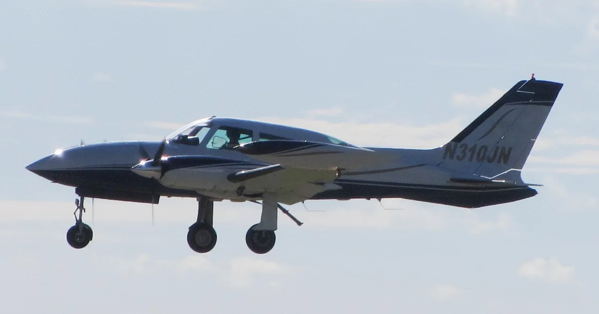
Most owners only have the POH. Here's the essential set for the CESSNA 310F.
CESSNA 310F for sale now

Free — save the 310F to your watchlist and track it in one place.
More CESSNA 310Fmanuals & documents
See all 45 →- CLEVELAND WHEELS & BRAKESParts Catalog
- Know When to Feather Your PropellerPilot's Operating Handbook
- EL-92 / 1 October 2023 Page 1 of 21 ELIGIBILITY LIST RevisionParts Catalog
- FAA Approved Model List For ADS-B Out Airworthiness Approval Peregrine STC NO. SA00756DEType Certificate
- Aircraft Aeroplanes General – Small (Up to 5700 kg MCTOW)Service Bulletins
- AC 21-34 v1.1 - Aircraft flight manuals - Civil Aviation Safety AuthorityAircraft Flight Manual
- 4910-13-P - Federal RegisterAirworthiness Directives
- TO 1-1-3 TECHNICAL MANUAL INSPECTION AND REPAIR OF AIRCRAFT INTEGRAL TANKS AND FUEL CELLSOther Documents
- OIL - TRANSMITTAL OF CONTINENTAL AEROSPACE TECHNOLOGIES CSB07-1A CONNECTING ROD PISTON PIN BUSHING INSPECTIONParts Catalog
- Goodrich® De-Icers Textron Aviation Replacement Part List Pneumatic de-ice boots Care products Prop-de-icers and hardware (RPL) Catalog 2021Parts Catalog
- FEDERAL AVIATION ADMINISTRATION (FAA) APPROVED MODEL LIST (AML) SA02511SE FOR CIES INC. CC284022 SERIES TSO C55a FUEL QUANTITY SENDERSSupplemental Type Certificate
- Canada (TCCA) Validation of the CGR-30C STCType Certificate
If you fly the CESSNA 310F, you may also be researching these.



In this document
Operation Instructions
The M-1 manifold pressure instrument features a 210-degree analog display and a digital display, providing accurate readings of manifold pressure. The analog display includes colored lights indicating normal, caution, and restricted ranges. The digital display measures absolute atmospheric pressure in the engine's manifold to .1 inches of mercury, allowing for precise monitoring and adjustments.
Installation Instructions
The installation section details the necessary steps for properly installing the M-1 instrument. It includes routing instructions for the circular connector, power and ground wires, and backlight wires. The manual stresses the importance of following FAA standards and ensuring that the instrument is calibrated correctly for the specific aircraft.
Wiring Diagram
A wiring diagram is included to assist with the installation of the M-1 instrument. It shows the connections for the circular connector, power, ground, and backlight wires, ensuring that the installation is performed correctly and safely.
Warranty Information
The warranty section outlines the terms under which the M-1 instrument is covered, including conditions for repair or replacement. It emphasizes that the warranty does not cover damages resulting from improper installation or misuse.
Specifications and Operating Features
This section provides detailed specifications of the M-1 instrument, including its operational limits and features. It highlights the importance of matching the instrument's limits with those specified in the aircraft's Pilot Operating Handbook.
Safety notes
- Improper installation may render the STC invalid and affect the safety of the aircraft.
- Pilots must understand the operation of the M-1 instrument before flying the aircraft.
- Keep the Operating Manual in the aircraft at all times.
Full document text
Manifold Pressure M-1 (Primary Replacement Instrument) Operating and Installation Instructions OI 0517912 Rev. A 63296 Powell Butte Hwy Bend, OR 97701 (541) 318-6060 iFlyEi.com. You must read this manual before installing or operating the instrument. This manual contains warranty and other information that may affect your decision to install this product and/or the safety of your aircraft. S/N:____________________________ Important Notice Important Notice Important Notice Important Notice Important Notice ***** MUST READ ***** ***** MUST READ ***** ***** MUST READ ***** ***** MUST READ ***** ***** MUST READ ***** If you think it is not important to read this manual, you're wrong! If you think it is not important to read this manual, you're wrong! If you think it is not important to read this manual, you're wrong! If you think it is not important to read this manual, you're wrong! If you think it is not important to read this manual, you're wrong! This manual This manual This manual This manual This manual contains important installation information that may affect the safety of your air- contains important installation information that may affect the safety of your air- contains important installation information that may affect the safety of your air- contains important installation information that may affect the safety of your air- contains important installation information that may affect the safety of your air- craft, delay your installation or affect the operation of your instrument. You craft, delay your installation or affect the operation of your instrument. You craft, delay your installation or affect the operation of your instrument. You craft, delay your installation or affect the operation of your instrument. You craft, delay your installation or affect the operation of your instrument. You Must Must Must Must Must read this manual prior to installing your instrument. read this manual prior to installing your instrument. read this manual prior to installing your instrument. read this manual prior to installing your instrument. read this manual prior to installing your instrument. Any deviation from these Any deviation from these Any deviation from these Any deviation from these Any deviation from these installation instructions is the sole responsibility of the installer/pilot and may installation instructions is the sole responsibility of the installer/pilot and may installation instructions is the sole responsibility of the installer/pilot and may installation instructions is the sole responsibility of the installer/pilot and may installation instructions is the sole responsibility of the installer/pilot and may render the STC invalid. render the STC invalid. render the STC invalid. render the STC invalid. render the STC invalid. Read the Warranty / Agreement Read the Warranty / Agreement Read the Warranty / Agreement Read the Warranty / Agreement Read the Warranty / Agreement. There is information in the Warranty / Agreement that may alter your decision to install this product. If you do not accept the terms of the Warranty / Agreement, do not If you do not accept the terms of the Warranty / Agreement, do not If you do not accept the terms of the Warranty / Agreement, do not If you do not accept the terms of the Warranty / Agreement, do not If you do not accept the terms of the Warranty / Agreement, do not install this product install this product install this product install this product install this product. This product may be returned for a refund. Contact Electronics International inc. for details. Check that the instrument make and model marked on the side of the instrument and on the invoice are correct before starting the installation. Check that the limit information on this instrument matches the published limits in your aircraft's P.O.H. or Flight Manual. Also, this information may be listed in the T.C. Data Sheet for your aircraft. Any AD's and/or STC's may set forth additional limitations on the operation of your engine. The limit informa- tion listed in the AML is for unmodified aircraft and is intended for reference only. It is the aircraft It is the aircraft It is the aircraft It is the aircraft It is the aircraft owner's and/or installer's responsibility to determine proper instrument calibration and range markings owner's and/or installer's responsibility to determine proper instrument calibration and range markings owner's and/or installer's responsibility to determine proper instrument calibration and range markings owner's and/or installer's responsibility to determine proper instrument calibration and range markings owner's and/or installer's responsibility to determine proper instrument calibration and range markings for your aircraft. for your aircraft. for your aircraft. for your aircraft. for your aircraft. On the front of this instrument you will find a red light marked with the maximum manifold pressure information. If there are any additional red or yellow lights on this instrument, the operating range of these lights can be found on a sticker located on the side of the instrument (see the AML at the back of this manual to decode this information). This instrument designates any "Caution Range" with yellow LEDs, any "Maximum and Minimum Limits" with Red LEDs and the "Safe Operating Range" with green LEDs. The "Safe Operating Range" on this instrument is equivalent to the green "Normal Operating Range" and any unmarked areas on a analog gauge. It is possible for any instrument to fail thereby displaying inaccurate high, low or jumpy readings. Therefore, you must be able to recognize an instrument failure and you must be proficient in operating your aircraft safely in spite of an instrument failure. If you do not have this knowledge, contact the FAA or a local flight instructor for training. The pilot must must must must must understand the operation of this product before flying the aircraft. Do not allow anyone
Show full textShow less
to operate the aircraft that does not know the operation of this product. Keep the Operating Manual in the Keep the Operating Manual in the Keep the Operating Manual in the Keep the Operating Manual in the Keep the Operating Manual in the aircraft at all times. aircraft at all times. aircraft at all times. aircraft at all times. aircraft at all times. Rev. C: 9/30/97* Contents Contents Contents Contents Contents Warranty............................................................................. Warranty............................................................................. Warranty............................................................................. Warranty............................................................................. Warranty............................................................................. 2 22 22 Operation Instructions ........................................................ Operation Instructions ........................................................ Operation Instructions ........................................................ Operation Instructions ........................................................ Operation Instructions ........................................................ 3 33 33 Instrument: ............................................................................... 3 Analog Display: ......................................................................... 3 Digital Display: .......................................................................... 3 Installation Instructions ....................................................... Installation Instructions ....................................................... Installation Instructions ....................................................... Installation Instructions ....................................................... Installation Instructions ....................................................... 4 44 44 Important Information and Initial Check Out: ............................. 4 Route The Circular Connector: .................................................. 5 Route the Power and Ground Wires: .......................................... 5 Route the Backlight Wires: ........................................................ 5 Route the (Optional) External Warning Control Line: .................. 6 Install the Instrument in the Panel: ............................................ 6 Connect the Circular Connector to the Instrument: .................... 6 Connect the Manifold Pressure Line: ......................................... 6 Check Instrument Operation: .................................................... 7 Wiring Diagram ................................................................. Wiring Diagram ................................................................. Wiring Diagram ................................................................. Wiring Diagram ................................................................. Wiring Diagram ................................................................. 8 88 88 M-1 Circular Connector ...................................................... M-1 Circular Connector ...................................................... M-1 Circular Connector ...................................................... M-1 Circular Connector ...................................................... M-1 Circular Connector ...................................................... 9 99 99 Specifications and Operating Features .................................. Specifications and Operating Features .................................. Specifications and Operating Features .................................. Specifications and Operating Features .................................. Specifications and Operating Features .................................. 1 0 1 0 1 0 1 0 1 0 STC Information ................................................................ STC Information ................................................................ STC Information ................................................................ STC Information ................................................................ STC Information ................................................................ 1 1 1 1 1 1 1 1 1 1 1 2 W W W W War ar ar ar arranty / ranty / ranty / ranty / ranty / Agr Agr Agr Agr Agreement eement eement eement eement Electronics International Inc. warrants this instrument and system components to be free from defects in materials and workmanship for a period of one year from the user invoice date. Electronics Interna- tional Inc. will repair or replace any item under the terms of this Warranty provided the item is returned to the factory prepaid. 1. This Warranty shall not apply to any product that has been repaired or altered by any person other than Electronics International Inc., or that has been subjected to misuse, accident, incorrect wiring, negligence, improper or unprofessional assembly or improper installation by any person. This warranty This warranty This warranty This warranty This warranty does not cover any reimbursement for any person’s time for installation, removal, assembly or repair. does not cover any reimbursement for any person’s time for installation, removal, assembly or repair. does not cover any reimbursement for any person’s time for installation, removal, assembly or repair. does not cover any reimbursement for any person’s time for installation, removal, assembly or repair. does not cover any reimbursement for any person’s time for installation, removal, assembly or repair. Electronics International retains the right to determine the reason or cause for warranty repair. 2. This warranty does not extend to any machine, vehicle, boat, aircraft or any other device to which the Electronics International Inc. product may be connected, attached, interconnected or used in conjunction with in any way. 3. The obligation assumed by Electronics International Inc. under this warranty is limited to repair, replacement or refund of the product, at the sole discretion of Electronics International Inc. 4. Electronics International Inc. is not liable for expenses incurred by the customer or installer due to factory updates, modifications, improvements, upgrades, changes, or any other alterations to the product that may affect the form, fit, function or operation of the product. 5. Personal injury or property damage do to misinterpretation or lack of understanding this product is solely the pilots responsibility. The pilot must must must must must understand the operation of this product before flying the aircraft. Do not allow anyone to operate the aircraft that does not know the operation of this product. Keep the Operating Manual in the aircraft at all times. 6. E. I. Inc. is not responsible for shipping charges or damages incurred under this Warranty. 7. No representative is authorized to assume any other liability for Electronics International Inc. in connection with the sale of Electronics International Inc. products. 8. If you do not agree to and accept the terms of this warranty, you may return the product for a If you do not agree to and accept the terms of this warranty, you may return the product for a If you do not agree to and accept the terms of this warranty, you may return the product for a If you do not agree to and accept the terms of this warranty, you may return the product for a If you do not agree to and accept the terms of this warranty, you may return the product for a refund. refund. refund. refund. refund. This Warranty is made only to the original user. THIS WARRANTY IS IN LIEU OF ALL OTHER THIS WARRANTY IS IN LIEU OF ALL OTHER THIS WARRANTY IS IN LIEU OF ALL OTHER THIS WARRANTY IS IN LIEU OF ALL OTHER THIS WARRANTY IS IN LIEU OF ALL OTHER WARRANTIES OR OBLIGATIONS: EXPRESS OR IMPLIED. MANUFACTURER EXPRESSLY WARRANTIES OR OBLIGATIONS: EXPRESS OR IMPLIED. MANUFACTURER EXPRESSLY WARRANTIES OR OBLIGATIONS: EXPRESS OR IMPLIED. MANUFACTURER EXPRESSLY WARRANTIES OR OBLIGATIONS: EXPRESS OR IMPLIED. MANUFACTURER EXPRESSLY WARRANTIES OR OBLIGATIONS: EXPRESS OR IMPLIED. MANUFACTURER EXPRESSLY DISCLAIMS ALL IMPLIED WARRANTIES OF MERCHANTABILITY OR FITNESS FOR A DISCLAIMS ALL IMPLIED WARRANTIES OF MERCHANTABILITY OR FITNESS FOR A DISCLAIMS ALL IMPLIED WARRANTIES OF MERCHANTABILITY OR FITNESS FOR A DISCLAIMS ALL IMPLIED WARRANTIES OF MERCHANTABILITY OR FITNESS FOR A DISCLAIMS ALL IMPLIED WARRANTIES OF MERCHANTABILITY OR FITNESS FOR A PARTICULAR PURPOSE. PURCHASER AGREES THAT IN NO EVENT SHALL MANUFAC- PARTICULAR PURPOSE. PURCHASER AGREES THAT IN NO EVENT SHALL MANUFAC- PARTICULAR PURPOSE. PURCHASER AGREES THAT IN NO EVENT SHALL MANUFAC- PARTICULAR PURPOSE. PURCHASER AGREES THAT IN NO EVENT SHALL MANUFAC- PARTICULAR PURPOSE. PURCHASER AGREES THAT IN NO EVENT SHALL MANUFAC- TURER BE LIABLE FOR SPECIAL, INCIDENTAL OR CONSEQUENTIAL DAMAGES, IN- TURER BE LIABLE FOR SPECIAL, INCIDENTAL OR CONSEQUENTIAL DAMAGES, IN- TURER BE LIABLE FOR SPECIAL, INCIDENTAL OR CONSEQUENTIAL DAMAGES, IN- TURER BE LIABLE FOR SPECIAL, INCIDENTAL OR CONSEQUENTIAL DAMAGES, IN- TURER BE LIABLE FOR SPECIAL, INCIDENTAL OR CONSEQUENTIAL DAMAGES, IN- CLUDING LOST PROFITS OR LOSS OF USE OR OTHER ECONOMIC LOSS. EXCEPT AS CLUDING LOST PROFITS OR LOSS OF USE OR OTHER ECONOMIC LOSS. EXCEPT AS CLUDING LOST PROFITS OR LOSS OF USE OR OTHER ECONOMIC LOSS. EXCEPT AS CLUDING LOST PROFITS OR LOSS OF USE OR OTHER ECONOMIC LOSS. EXCEPT AS CLUDING LOST PROFITS OR LOSS OF USE OR OTHER ECONOMIC LOSS. EXCEPT AS EXPRESSLY PROVIDED HEREIN, MANUFACTURER DISCLAIMS ALL OTHER LIABILITY EXPRESSLY PROVIDED HEREIN, MANUFACTURER DISCLAIMS ALL OTHER LIABILITY EXPRESSLY PROVIDED HEREIN, MANUFACTURER DISCLAIMS ALL OTHER LIABILITY EXPRESSLY PROVIDED HEREIN, MANUFACTURER DISCLAIMS ALL OTHER LIABILITY EXPRESSLY PROVIDED HEREIN, MANUFACTURER DISCLAIMS ALL OTHER LIABILITY TO PURCHASER OR ANY OTHER PERSON IN CONNECTION WITH THE USE OR PERFOR- TO PURCHASER OR ANY OTHER PERSON IN CONNECTION WITH THE USE OR PERFOR- TO PURCHASER OR ANY OTHER PERSON IN CONNECTION WITH THE USE OR PERFOR- TO PURCHASER OR ANY OTHER PERSON IN CONNECTION WITH THE USE OR PERFOR- TO PURCHASER OR ANY OTHER PERSON IN CONNECTION WITH THE USE OR PERFOR- MANCE OF MANUFACTURER’S PRODUCTS, INCLUDING SPECIFICALLY LIABILITY IN MANCE OF MANUFACTURER’S PRODUCTS, INCLUDING SPECIFICALLY LIABILITY IN MANCE OF MANUFACTURER’S PRODUCTS, INCLUDING SPECIFICALLY LIABILITY IN MANCE OF MANUFACTURER’S PRODUCTS, INCLUDING SPECIFICALLY LIABILITY IN MANCE OF MANUFACTURER’S PRODUCTS, INCLUDING SPECIFICALLY LIABILITY IN TORT. TORT. TORT. TORT. TORT. Operation Instructions Operation Instructions Operation Instructions Operation Instructions Operation Instructions M-1 M-1 M-1 M-1 M-1 0517932 Instrument: Instrument: Instrument: Instrument: Instrument: The M-1 is a precision manifold pressure instrument featuring a 210 degree analog display and a digital display. These two displays have many advantages over conventional analog gauges as described below. Also, the M-1 features long-term accuracy and reliability. Since the M-1 does not incorporate any moving parts (needles, bearings, springs, etc.) there is little to go wrong or wear out. The internal microprocessor assures accuracy and repeatability. Analog Display: Analog Display: Analog Display: Analog Display: Analog Display: The 210 degree analog display provides a quick reference of manifold pressure with respect to its operating range. At a glance you can get a relative idea of where in the range you are operating the engine and how close to the maximum limit you are. Precise information is provided in the digital display. An advantage of the analog display is its ability to emit a green, yellow or red light. With a quick glance you can determine if you’re operating in a normal, caution or restricted range. Also, when you exceed a maximum limit the red light will blink 20 times at full intensity to catch your attention and warn you that a maximum limit has been violated. After 20 blinks the red light will stop blinking and display continuous red so it does not distract you. During night operation the analog lights may be too bright. If so, turn the panel light rheostat up and the analog lights will dim. The red (maximum limit) light will always be displayed at full intensity. Digital Display: Digital Display: Digital Display: Digital Display: Digital Display: The M-1 measures absolute atmospheric pressure in the engine’s manifold to .1 inches of mercury. This reading should not be confused with barometric pressure. Barometric pressure readings are altitude compensated to sea level. For every 100 feet above sea level there is approximately .1 inches of mercury less manifold pressure available to the engine. That means at 1000 feet above sea level with a barometric reading of 30.0 inches of mercury, the maximum manifold pressure available for a non-turbocharged aircraft is 29.0 inches of mercury. Less manifold pressure means less power. Two other factors affecting manifold pressure are induction loss and ram air. Induction loss is the normal drop in pressure across the carburetor and intake manifold. This will lower your available manifold pressure by approximately 1.0 inches of mercury. Ram air, on the other hand, will increase your manifold pressure. Ram air is the normal compression of air in the manifold caused by airspeed and dependent on the location of the intake air pickup point. At 145 knots the maximum increase in manifold pressure available is 1.0 inches of mercury. 3 Rev. A: 6/16/92 The M-1 can detect a change in manifold pressure for every 100 feet of elevation or .1 inches change in barometric pressure. This allows for precise setting and monitoring of the manifold pressure. If the digital display backlight has been permanently powered up (as recommended), the digital display will be easier to see during low ambient light conditions and at night. Installation Instructions Installation Instructions Installation Instructions Installation Instructions Installation Instructions M-1 M-1 M-1 M-1 M-1 Important Information and Initial Check Out: Important Information and Initial Check Out: Important Information and Initial Check Out: Important Information and Initial Check Out: Important Information and Initial Check Out: 1. The installer and aircraft owner must read the Warranty before starting the installation. The installer and aircraft owner must read the Warranty before starting the installation. The installer and aircraft owner must read the Warranty before starting the installation. The installer and aircraft owner must read the Warranty before starting the installation. The installer and aircraft owner must read the Warranty before starting the installation. There is information in the Warranty that may alter your decision to install this instrument. If you do not accept If you do not accept If you do not accept If you do not accept If you do not accept the terms of the Warranty, do not install this instrument. the terms of the Warranty, do not install this instrument. the terms of the Warranty, do not install this instrument. the terms of the Warranty, do not install this instrument. the terms of the Warranty, do not install this instrument. 2. If you are not an FAA Certified Aircraft Mechanic familiar with the issues of installing aircraft mani- 2. If you are not an FAA Certified Aircraft Mechanic familiar with the issues of installing aircraft mani- 2. If you are not an FAA Certified Aircraft Mechanic familiar with the issues of installing aircraft mani- 2. If you are not an FAA Certified Aircraft Mechanic familiar with the issues of installing aircraft mani- 2. If you are not an FAA Certified Aircraft Mechanic familiar with the issues of installing aircraft mani- fold pressure instruments, fold pressure instruments, fold pressure instruments, fold pressure instruments, fold pressure instruments, Do Not attempt to install this instrument. Do Not attempt to install this instrument. Do Not attempt to install this instrument. Do Not attempt to install this instrument. Do Not attempt to install this instrument. The installer should use current The installer should use current The installer should use current The installer should use current The installer should use current aircraft standards and practices to install this instrument (refer to AC 43.13). aircraft standards and practices to install this instrument (refer to AC 43.13). aircraft standards and practices to install this instrument (refer to AC 43.13). aircraft standards and practices to install this instrument (refer to AC 43.13). aircraft standards and practices to install this instrument (refer to AC 43.13). 3. Check that any necessary FAA Approvals (STC's, etc.) are available for your aircraft before starting Check that any necessary FAA Approvals (STC's, etc.) are available for your aircraft before starting Check that any necessary FAA Approvals (STC's, etc.) are available for your aircraft before starting Check that any necessary FAA Approvals (STC's, etc.) are available for your aircraft before starting Check that any necessary FAA Approvals (STC's, etc.) are available for your aircraft before starting the installation. The FAA Approved Model List (AML) is located at the back of this manual. the installation. The FAA Approved Model List (AML) is located at the back of this manual. the installation. The FAA Approved Model List (AML) is located at the back of this manual. the installation. The FAA Approved Model List (AML) is located at the back of this manual. the installation. The FAA Approved Model List (AML) is located at the back of this manual. Resolve Resolve Resolve Resolve Resolve any issues you may have before starting the installation. any issues you may have before starting the installation. any issues you may have before starting the installation. any issues you may have before starting the installation. any issues you may have before starting the installation. 4. Before starting the installation, read the entire Installation Instructions and resolve any issues you may have. This may eliminate any delays once the installation is started. 5. Check that the instrument make and model marked on the side of the instrument and on the invoice are correct before starting the installation. 6. Check that the limit information on this instrument matches the published limits in your aircraft's P.O.H. or Flight Manual. Also, this information may be listed in the T.C. Data Sheet for your aircraft. Any AD's and/or STC's may set forth additional limitations on the operation of your engine. The limit information listed in the AML is for unmodified aircraft and is intended for reference only. It is the aircraft owner's It is the aircraft owner's It is the aircraft owner's It is the aircraft owner's It is the aircraft owner's and/or installer's responsibility to determine proper instrument calibration and range markings for your and/or installer's responsibility to determine proper instrument calibration and range markings for your and/or installer's responsibility to determine proper instrument calibration and range markings for your and/or installer's responsibility to determine proper instrument calibration and range markings for your and/or installer's responsibility to determine proper instrument calibration and range markings for your aircraft. aircraft. aircraft. aircraft. aircraft. On the front of this instrument you will find a red light marked with the maximum manifold pressure information. If there are any additional red or yellow lights on this instrument, the operating range of these lights can be found on a sticker located on the side of the instrument (see the AML at the back of this manual to decode this information). This instrument designates any "Caution Range" with yellow LEDs, any "Maximum and Minimum Limits" with Red LEDs and the "Safe Operating Range" with green LEDs. The "Safe Operating Range" on this instrument is equivalent to the green "Normal Operating Range" and any unmarked areas on a analog gauge. 4 Rev. C: 9/30/97 Do not attempt to remove or replace the limit stickers on this instrument. If the manifold pressure limits for your engine do not match those which are marked on this instrument send this unit back to Electronics International Inc. for recalibration. DO NOT install or use a primary engine instrument that is not prop- erly calibrated for your aircraft. 7. Before starting the installation make sure the unit will fit in the location you intend to install it without obstructing the operation of any controls. 8. If this instrument is to replace an existing unit in the aircraft, it is the installer's responsibility to move or replace any existing instruments or components in accordance with FAA approved methods and proce- dures. The following Installation Instructions do not cover moving or the removal of any existing instru- ments or components. Route The Circular Connector: Route The Circular Connector: Route The Circular Connector: Route The Circular Connector: Route The Circular Connector: Starting from under the instrument panel, route the circular connector wire harness up to the instrument mounting location. (See the wiring diagram at the back of this manual). Place the circular connector about 8 inches back from the panel. Tie wrap the harness in place approximately 1 foot back from the circular connector. This will allow the harness to be flexible and accomodate varying lengths in instrument wires. Be sure these Be sure these Be sure these Be sure these Be sure these wires do not obstruct the freedom of travel of any controls. wires do not obstruct the freedom of travel of any controls. wires do not obstruct the freedom of travel of any controls. wires do not obstruct the freedom of travel of any controls. wires do not obstruct the freedom of travel of any controls. Route the Power and Ground Wires: Route the Power and Ground Wires: Route the Power and Ground Wires: Route the Power and Ground Wires: Route the Power and Ground Wires: Route the red wire in the harness to the aircraft’s 12 or 24 volt main or emergency bus as applicable via an independent circuit breaker (five amps or less). An alternate method would be to route the red lead to the bus via a one amp in-line fuse. With this method a spare fuse should be kept in the aircraft. Route the black wire in the harness to a good ground . Tie wrap these wires so they do not obstruct the Tie wrap these wires so they do not obstruct the Tie wrap these wires so they do not obstruct the Tie wrap these wires so they do not obstruct the Tie wrap these wires so they do not obstruct the freedom of travel of any controls. freedom of travel of any controls. freedom of travel of any controls. freedom of travel of any controls. freedom of travel of any controls. Route the Backlight Wires: Route the Backlight Wires: Route the Backlight Wires: Route the Backlight Wires: Route the Backlight Wires: Connect the backlight wires as follows: 1. It is recommended to permanently power up the digital display backlight. a) For a 12-volt system connect the white/brown wire to the instrument Red Power Lead. Con- nect the white/red wire to ground (see Wiring Diagram). b) For a 24-volt system leave the white/brown open. Connect the white/red wire to the instrument Red Power Lead (see Wiring Diagram). 2. Connect the white/orange wire to the panel light rheostat. This wire will dim the analog LED’s for night operation when the panel lights are turned on. If this line is left open, the analog LED's will remain at full intensity at all times. Also, if the voltage on this line drops below 11.5 volts, the analog LED's will be displayed at full intensity. Tie wrap all wires so they do not obstruct the freedom of Tie wrap all wires so they do not obstruct the freedom of Tie wrap all wires so they do not obstruct the freedom of Tie wrap all wires so they do not obstruct the freedom of Tie wrap all wires so they do not obstruct the freedom of travel of any controls. travel of any controls. travel of any controls. travel of any controls. travel of any controls. 5 Rev. C: 9/30/97 Route the (Optional) External Warning Control Line: Route the (Optional) External Warning Control Line: Route the (Optional) External Warning Control Line: Route the (Optional) External Warning Control Line: Route the (Optional) External Warning Control Line: The white/yellow wire can be connected to an external light (AL-1), buzzer (ATG-1), voice annunciator (AV- 17), a relay, etc. This wire grounds when the red warning light is on. The current in this line must be limited to 2/ 10 of an amp maximum. Exceeding this limit will damage the unit. If this feature is not used, leave this line open. Tie wrap this wire so it does not obstruct the freedom of travel of any controls. Tie wrap this wire so it does not obstruct the freedom of travel of any controls. Tie wrap this wire so it does not obstruct the freedom of travel of any controls. Tie wrap this wire so it does not obstruct the freedom of travel of any controls. Tie wrap this wire so it does not obstruct the freedom of travel of any controls. Install the Instrument in the Panel: Install the Instrument in the Panel: Install the Instrument in the Panel: Install the Instrument in the Panel: Install the Instrument in the Panel: Install the instrument from behind the instrument panel using 6 x 32 screws. These screws should not be any longer than 1/2". Connect the Circular Connector to the Instrument: Connect the Circular Connector to the Instrument: Connect the Circular Connector to the Instrument: Connect the Circular Connector to the Instrument: Connect the Circular Connector to the Instrument: 1) Push the two mating connectors together and twist them until they snap into position. 2) Turn the locking ring on the instrument connector clockwise (1 1/2 turns) until it locks into position. Connect the Manifold Pressure Line: Connect the Manifold Pressure Line: Connect the Manifold Pressure Line: Connect the Manifold Pressure Line: Connect the Manifold Pressure Line: Connect the aircraft manifold pressure line to the pressure port on the back of the instrument. Be sure this line is tight. This pressure port is a 1/4" flare union and is standard for most manifold pressure gauges. Care should be taken not to put excess pressure on the flexible line between the flare union and the pressure transducer mounted on the back of the instrument. The Pressure Transducer Port can break. Make sure the flexible pres- Make sure the flexible pres- Make sure the flexible pres- Make sure the flexible pres- Make sure the flexible pres- sure line does not have any kinks. sure line does not have any kinks. sure line does not have any kinks. sure line does not have any kinks. sure line does not have any kinks. 6 Rev. C: 9/30/97 Note Note Note Note Note::::: Some aircraft have a very small hole in the maniflold pressure line to create an airflow in the line. This small flow of air keeps fuel from working its way into the manifold pressure gauge or tranducer whitch can cause damage over time. 7 Rev. A: 6/16/92 Check Instrument Operation: Check Instrument Operation: Check Instrument Operation: Check Instrument Operation: Check Instrument Operation: Check instrument operation as follows: 1. Turn the master switch on (engine off) and verify that the instrument sequences through all the analog lights and reads approximately barometric pressure less .1 inches of mercury for every 100 feet you are above sea level. A problem at this step could be caused by poor connections on the red and/or black leads. 2. Check the digital display backlight. With high or medium ambient light it is hard to see the digital display backlight (it is only required during low ambient light conditions but should be on all the time). 3. Start the aircraft engine and check the digital and analog display to read properly. A problem at this step could be caused by a restriction or leak in the manifold pressure line. Never pressurize this line with the Never pressurize this line with the Never pressurize this line with the Never pressurize this line with the Never pressurize this line with the M-1 connected. M-1 connected. M-1 connected. M-1 connected. M-1 connected. This will damage the pressure transducer. Manifold Pressure (M-1) Manifold Pressure (M-1) Manifold Pressure (M-1) Manifold Pressure (M-1) Manifold Pressure (M-1) Wiring Diagram Wiring Diagram Wiring Diagram Wiring Diagram Wiring Diagram 8 Do not use screws longer than 1/2" (4 ea.). Analog LED Lighting Control Line, connects to Panel Light Rheostat. 12/24 volts dims the analog LEDs. (Optional) External Warning Control Line. Can be connected to a relay to control an external light, buzzer, etc. Grounds when Red Warning Light is on. Current must be limited to 2/10 amp maximum. 24V Backlight Control Line, connects to Red Power Lead for 24V system. Connects to ground for 12 Volt System. Connects to ground for 12 Volt System. Connects to ground for 12 Volt System. Connects to ground for 12 Volt System. Connects to ground for 12 Volt System. 12V Backlight Control Line, connects to Red Power Lead for 12V system. 12 volts turns on the digital display backlight. Ground Lead, connects to Ground. Power Lead, connects to 12 or 24 Volt Bus via one amp fuse. White/Yel B l a c k R e d White/ Brwn White/Red White/ Orng Circular Connector Pressure Port. Aircraft Manifold Pres- sure Line. Wire Harness WD 0313911 Rev. A: 6/16/92 M-1 Circular Connector M-1 Circular Connector M-1 Circular Connector M-1 Circular Connector M-1 Circular Connector 3 1 4 7 9 6 Connecting Cable Harness, Back View (wire side) Instrument Connector, Front View OR Note: See Wiring Diagram for hook up information. W/ Yel Blk Red W/ Org W/ Red W/ Brn 9 Rev. A: 6/16/92 10 Specifications and Operating Features Specifications and Operating Features Specifications and Operating Features Specifications and Operating Features Specifications and Operating Features S0515911 5/15/91 Model: M-1 (Manifold Pressure Instrument) Case Dimensions: 2.5" x 2.5" x 3.65" depth, 2 1/4" Bezel. Weight: 13 Oz. Environmental: Meets TSO C45. Power Requirements: 7.5 to 30 Volts, 1/10 Amp. Analog Display: 17 High Intensity Light Emitting Diodes (LEDs) in a 210 degree arc with Intensity Control Line available for dimming. Sequential flash test on power up. Microprocessor eliminates LED hunting (flicker). Red LEDs: If the Analog Display goes from a Green LED or Yellow LED to a Red LED, the Red LED will blink 20 times then go solid red. Digital Display: LCD (viewable in direct sunlight), with 12 and 24 volt backlight control wires for night operation. Displays “888” on power up. Accuracy: 1% in accordance with TSO C45. Resolution: .1 In. Hg. Max Range: Max Allowable: 60 In. Hg. for standard unit. Max Allowable: 120 In. Hg. for units with requirments over 45 In. Hg. Update Time: 3 times per second. Pressure Port: 1/4 inch male flare union mounted on a .170 I.D. flexible tube located on the back of the unit. External Warning Control Line: Grounds when any Red Warning Light is on or blinking. Current should be limited to 2/10 amp. Rev. C: 9/30/97 'tinittd ~ t a t t J or S!mrrica Btpartmtnr of 1Cran.sporraoon -.ftdmll Sl\liation Sldmini.Sttation ~ u p p l r m r n t a l 1 t ~ p r <rrrtificat£ ~ SA5926NM ~ ~ ~ ~ ~ ~ Electronics International, Inc. ~ ~ ~ ~ ~ ~ . / k ~ ~ ~ ¥ ' ~ * * ~ ~ ~ - ~ ~ . . *See attached FAA Approved Model List (AML) vltak: *No. SA5926NM for list of approved airplane , . , ~ . . *models and applicable regulations. ~ ~ _ , ~ ' ~ ~ ~ ~ ~ ~ . . Electronics International manifold pressure instrument manufactured ana installed in accordance with the drawings and installation instructions specified on the FAA Approved Model List (AML) of this STC, or later FAA approved revisions. Approval of this change in type design applies to the above ~ n ~ ~ ~ - r u / ~ . . . model aircraft only. This approval should not be extended to other aircraft of this model on which other previously approved modifications are incorporated unless it is determined that the relationship between this change and any of those other previously approved modifications, including changes in type design, will introduce no adverse effect upon the airworthiness of that aircraft. A copy of this certificate and FAA Approved Model List (AML) No. SA5926NM, dated February 17, 1993, or later FAA approved revision, must be maintained as part of the ~ m a n e n t records for the modified aircraft . . / k ~ ~ ~ j k ~ " ' ? ~ h ~ ~ . l k / w ~ / - ~ - v a ~ 4 k / / _ . ; u u ; r v . N v # ' / A L R z / . d ~ A < M ? & t · . , · ~ . c { a ~ ~ ~ . o - , . . 8 ' k ~ ~ k - e : v ~ a ~ . 6 : r . / k . r U , . u : m : J b a 4 - 1 " ¥ 1 k y ~ ~ ~ w - . ~ ...k · _ . , f ~ « a & < - _ . : November 10, 1992 !il...u.~~n.ce-: February 17, 1993 Any alteration of this certificate is punishable ~ y a fme of not exceeding II ,000, or imprisonment not exceeding 3 years, or both. This urtificate may be transferred in accordance with FAR 21.47. FAA fOIM 8110-2 (10-68) FAA Approved Model List (AML) SA5926NM For Electronics International Manifold Pressure Instrument Issue Date: February 17, 1993 Original Certification FAA Sealed Installation Type Basis Drawings Instructions AML Aircraft Aircraft Certificate for Instrument Model Number Amended Item Make Model Number Alteration Number Rev Number Rev. No (See Note 1) Date -.. -... --------------- ------------------- ............................ .. ................................ TD0328921 None 01 0517912 c ------------------ ---- -------- ... ............... 1. Aeronca Inc. 50-LA, . 65-LA, -LB A-702 Car 4a II II II II M-1-G100R320 6/3/94 (See American, 15AC, S15AC A-802 Car 3 II II II II M-1-G100R320 II Bellanca) 2. Aerospatiale See Socata. ............................. ------------- --------- -- ...... ---------- ------- ------------------------------ 6/3/94 3. American Blimp A-60, A-60+ AS1NM FAR 21 II II II II M·1-G100R320 10/30/97 A-1-50 S00002SE II II II II M-1-G100R320 II 4. American 7AC, 7BCM, 7DC, A-759 CAR 4a M-1-G100R320 6/3/94 Champion S7DC, 7CCM, S7CCM, II II M-1-G100R320 II (Also see 7JC, 7EC, S7EC, II II M-1-G100R320 II Aeronca & S7CF, S7GC, 7HC, II II M-1-G100R320 II Bellanca) 7GCA, 7GCB, 7KC, II II M-1-G100R320 II 7GCBA, 7GCAA, II II M-1-G100R320 II 7GCBC, 7KCAB, 7ECA II II M-1-G100R320 II 8KCAB, 8GCBC A21CE Far 23 M-1-G100R320 10/30/97 11AC, BC, S11AC, BC A-761 Car 4a M-1-G100R320 II 11C, S11C A-796 Car 3 M-1-G100R320 II 5. Aviat Inc. A-1 A22NM FAR 23 II II II II M-1-G100R320 6/3/94 S-1S, S-1T I S-2, A8SO FAR 21 II II II II II II S-2A, S-2S, S-28 II II II II II II II II Page 1 of 9 FAA Approved Model List (AML) SA5926NM For Electronics International Manifold Pressure Instrl.lllent Issue Date: February 17, 1993 Original Certification FAA Sealed Installation Type Basis Drawings Instructions AML Aircraft Aircraft Certificate for Inst r ument Model Number Amended Item Make Model Number Alteration Number Rev Number Rev. No (See Note 1) Date -- .... --------------- ...................................... ----------- .. .......................... TD0328921 None OI 0517912 c ----------------·------------- ------- 6. Beech Aircraft 18 Series A-684 Bul 7A M·1·G100R320 8/15/93 Corp. 19A, B19 I M19A A1CE CAR 3 II M·1·G100R320 23, A23, A23A II M·1·G100R320 A23·24, C23, B23 II M·1·G100R320 A24, A24R, B24R II M·1·G100R320 C24R II M·1·G100R320 35, A35, 835, C35 A-777 M·1·G100R296 035, E35, F35, G35 M·1·G100R296 35R, H35, J35, K35 M·1·G100R296 M35, N35, P35, S35 M·1·G100R296 V35, V35A, V35B M·1·G100R296 35·33, 35·A33 M·1·G100R296 35·B33, 35·C33 M·1·G100R296 35·C33A, E33, E33A M·1·G100R296 E33C I F33 I F33A M·1·G100R296 F33C,G33, 36, A36 3A15 M·1·G100R296 A36TC, B36TC II M·1·G100R360 45, A45, 045 5A3 CAR 3 M·1·G100R320 10/30/97 SO,C,D,E,F,G,H,J 5A4 II M·1·G100R450 8/15/93 ASS, B55, B55B, C55 3A16 II M·1·G100R296 C55A, 055 II II M·1·G100R296 OSSA, E55, E55A II II M·1·G100R296 56TC, A56TC II II M·1·G100R415 58, 58A A23CE FAR 23 M·1·G100R296 58P, 58PA, 58TC II II M·1·G100R395 58TCA II II M·1·G100R395 60, A60, B60 A12CE II M·1·G100R415 65,·80,·88,B,·90 3A20 CAR 3 M·1·G100Y450R480 A65,·8200,70,A90 II II M·1·G100Y450R480 70 II II M·1·G100Y450R480 76 A29CE FAR 23 M·1·G100Y450R480 77 A30CE II M·1·G100R320 95, B95, B95A 3A16 CAR 3 M·1·G100R290 D95A, E95, 95·55 II II M·1·G100R296 95·A55 I ·B55 II II - M·1·G100R296 95·B55A, ·B55B II II M·1·G100R296 95·C55 I ·C55A II II M·1·G100R296 7. Bellanca 14·19, 17·30, 17·31 1A3 CAR 3 II II II II M·1·G100R320 6/3/94 Aircraft 17·31TC II II II II II II M·1·G100R270 II Corporation 17·30A, 17·31A A18CE FAR 23 II II II II M·1·G100R320 II 17·31ATC II II II II II II M·1·G100R270 II 8. Boeing Aircraft A75L3,A75N1,A75J1 A-743 Car 4a II II II II M·1·G100R320 10/30/97 A75L300, IB75A Page 2 of 9 FAA Approved Model List (AML) SA5926NM For Electronics International Manifold Pressure Instrument Issue Date: February 17, 1993 Original Certification FAA Sealed Installation Type Basis Drawings Instructions AML Aircraft Aircraft Certificate for Instrument Model Number Amended I tern Make Model Number Alteration Number Rev Number Rev. No (See Note 1) Date -..... - --------------- ------------------- .... ...... ............. ___ ___ ____ .. __ TD0328921 None 01 0517912 c - -- --- -- ---------------------- ------- 9. Cessna Aircraft 120, 140, 140A A· 768 CAR 4a II II M·1·G100R320 8/15/93 Corp. 150, 150A, 1508 3A19 CAR 3 II II 150C, 150D II II II 150E, 150F, 150G II II II 150H, 150J, F150F II II II 150J, 150K, A150K II II I 150L, A150L II I 150M, A150M II 152, A152 II 170, 170A, 1708 A-799 172, 172A, 172B 3A12 172C, 172D, 172E II 172F I 172G, 1721 II 172K, 172L, 172M II 172N, 172P II 172RG, P172D 3A17 CAR 3 R172E, R172F, R172G II II R172H, R172J, R172K II II 175,175A,175B,175C II II 6/3/94 177 I 177A, 177B A13CE FAR 23 8/15/93 177RG A20CE II I 180, 180A, 1808 5A6 CAR 3 180C, 180D I 180E II 180F , 180G, 180H II 180J, 180K II 182, 182A, 182B 3A13 182C, 182D, 182E II 182F I 182G, 182H II 182J, 182K II 182L, 182M, 182N, II I 182P I 182Q II 182R, R182 II T182, TR182 II I M·1·G100R350 185 I 185A, 1858 3A24 M·1·G100R320 185C, 185D I 185E II II A185E, A185F II II 188, 188A, 188B A9CE FAR 23 II A188, A188A II II II T188C II II M·1-G100R350 190, 195, 195A A-790 CAR 3 M-1-G100R320 9!30!97 205, 205A 3A21 II II 8/15/93 Page 3 of 9 FAA Approved Model List (AML) SA5926NM For Electronics International Manifold Pressure lnstr1.111ent Issue Dat e: February 17, 1993 Original Certification FAA Sealed Installation Type Basis Drawings Instructions AML Aircraft Aircraft Certificate for Instrument Model Number Amended Item Make Model Number Alteration Number Rev Number Rev. No (See Note 1) Date ..... -... --------------- ------------------- ----------- ---------- --- TD0328921 None 01 0517912 c -------- ----------- ----------- ------- 9. Cessna Aircraft 206&TP,A,B,C,D,E,F, A4CE CAR 3 M-1-G100R320 8/15/93 Corp. (Cont.> U206&TU,A,B,C,D,E,F II II II TU206F 207, 207A II II M-1-G100R325 T207, T207A A16CE FAR 23 M-1-G100R320 210, 210A II II M-1-G100R325 2108, 210C, 210D, 3A21 CAR 3 CAR 3 M-1-G100R320 210F 3A21 II 210-5, 210-SA II II T210F, 210G, T210G, II M-1-G100Y350R365 210H, 210J II M-1-G100R320 T210H, T210J, 210M, II M-1-G100Y350R365 210K, 210L II M-1-G100R320 T210L, T210F, T210M II M-1-G100Y350R365 210N, P210N, P210R II M-1-G100R320 T210N II M-1-G100Y350R365 305A, 3058, 305C II CAR 3 M-1-G100R320 305D, 305E, 305F 5A5 II II 310, 310A, 3108 II CAR 3 II 310C, 310D, 310E 3A10 II 310F, 310H, E310H II 3101, 310J II E310J, 310K, 310L II 310N, 310P, 310R II T310P, T310R M-1-G100R350 T310Q II 310Q M-1-G100R320 320, -A, -B, -C I II 3200, -E, -F 3A25 II 336 II I II 337, 337A, 3378 A2CE II 337E, 337C, G, H A6CE II T337B, T337E, T337C II M-1-G100R370 3370, P337B II M-1-G100R320 M337B, 337H 3A25 II T337D, T337H, G II I M-1-G100R370 340, 340A II M-1-G100R320 401, 401A, 4018 II I M-1-G100R345 402, 402A, 4028 A7CE II II 402C II II M-1-G100R390 404 II II M-1-G100R400 411, 411A II II M-1-G100R345 414, 414A II II M-1-G100R380 421, 421A, 4218 II II M-1-G100R395 421C, 425 II II M-1-G100R395 Page 4 of 9 FAA Approved Model List (AML) SA5926NM For Electronics International Manifold Pressure Instrument Issue Date: February 17, 1993 Original Certification FAA Sealed Installation Type Basis Drawings Instructions AML Aircraft Aircraft Certificate for Instrument Model Number Amended Item Make Model Number Alteration Number Rev Number Rev. No (See Note 1) Date ---- ------------- -- ------------------- ----------- ---- -- ------- TD0328921 None OI 0517912 c ------- --------------- -------- .................... 10. Coomander 112, 1128 A12SO FAR 23 II II II II M-1-G100R320 6/3/94 Aircraft 114 Seri es II II II II II II M-1 - G100R320 II 112TC, 112TCA II II II II II II M-1-G100R420 II 500,A,B,U , S,520 6A1 Car 3 II II II II M-1-G100R320 10/30/97 560,A,E II II II II II II M-1-G100R320 II 11. DeHavi lland DHC-2 A-806 CAR 10 II II II II M-1-G100Y335R365 6/3/94 Aircraft of DHC-3 A-815 II II II II II M-1-G100Y335R365 II Canada, Ltd. 12. Extra EA-300,-300S,-300L A67EU FAR 23 II II II II M-1-G100R320 10/30/97 Flugzeugbau EA-300/200 13. Fairchild 24 esc A-706 Bul 7A II II II II M-1-G100R320 10/30/97 24 R9 A-707 Car 4a II II II II M-1-G100R320 II 14. Gn.mnan F8F-2 AR-32 Car 8 II II II II M-1-G100R440 10/30/97 AF-2S AR-36 II II II II II M-1-G100R470 II 15. Gulfstream AA-1, - 1A, - 18, -1C A16EA FAR 23 II II II II M-1-G100R320 6/3/94 American Corp. AA-5, -SA, -SB II II II II II II II II (Grl..ml18n Aircraft) 16. Hel io Aircraft 15A, 20 3A3 Car 4a II II II II M-1-G100R320 10/30/97 17. Helio H-250,-295,-395&A 1A8 Car 3 II II II II M-1-G100R320 10/30/97 Enterprise H-391&B, -800,F-295 II II II II II II M-1-G100R320 II HT-295 II II II II II II M-1-G100R291 II H-700 II II II II II II M-1-G100R490 II 18. Interceptor 200,A,B,D 3A18 Car3 II II II II M-1-G100R320 10/30/97 (Aero Commander) (Meyers) 19. Lake See Revo. ----------- .................................... ....................... -... -- .. ......................... .. --- .. ...... ---------------------- -------- 6/3/94 20. Luscombe 8,A,B,C,D,E,F,T-8F A-694 CAR 4a II II II II M-1-G100R320 6/3/94 21. Maule M-4,C,S,T,-180C,S 3A23 CAR 3 II II II II M-1-G100R320 6/3/94 M-4T,-210,-220,C,S II II II II II II II II M-5,-180C,-200 II II II II II II II II M-5-210C,TC,220C II II II II II II II II M-5-235C II II II II II II II II M-6-180 II II II II II II II II MX-7-235 II II II II II II II II Page 5 of 9 FAA Approved Model List (AML) SA5926NM For Electronics International Manifold Pressure Instrument Issue Date: February 17, 1993 Original Certification FAA Sealed Installation Type Basis Drawings Instructions AML Aircraft Aircraft Certificate for Instrument Model Number Amended Item Make Model Number Alteration Number Rev Number Rev. No (See Note 1> Date --- ... ---- -- -- -- ----- ------------------- ......................... ................................ TD0328921 None OI 0517912 c ------------------------------ ------- 22. Mooney Aircraft M20 2A3, CAR 3 M-1-G100R320 None Corp. M20A II M20B II M20C M20D M20E M20F M20G M20J I M20K II M-1·G OOR400 M20K w/TSI0 - 360-MB1 II M-1-G100R360 M20L II M-1-G100R320 M20M II M-1-G100R380 M22 A6SW II M-1-G100R370 23. Moravan Z 526L A30EU Far 21 II II II II M-1-G100R320 10/30/97 Z 242L,143L A76EU Far 23 II II II II M-1-G100R320 II 24. Navion See Thompson. ........................... .. ........................... .................... ---- .. ....................... ... ---- .... ------------------------------ 6/3/94 Page 6 of 9 FAA Approved Model List (AML) SA5926NM For Electronics International Manifold Pressure l n s t r ~ . m e n t Issue Date: February 17, 1993 Original Certification FAA Sealed Installation Type Basis Drawings Instructions AML Aircraft Aircraft Certificate for l n s t r ~ . m e n t Model Number Amended Item Make Model Number Alteration Number Rev Nl.lllber Rev. No (See Note 1) Date ---- --------------- ------------------- ----------- ----- -------- TD0328921 None 01 0517912 c -------- --- ---- -- - -- --- ------- -- ----- 25. Piper Aircraft PA-12,12S A-797 Car 3 M-1-G100R320 10/30/97 . Corp. PA-14 A-80 II M-1-G100R320 II PA-18&18A&18S, 1A2 CAR 3 M-1-G100R320 5/10/93 -125,-135,-150 II M-1-G100R320 PA-20&205,115,135 1A4 M-1-G100R320 PA-22&S,135,150,160 1A4 M-1-G100R320 PA-23 1A10 M-1-G100R320 PA-23-160 II M-1-G100R320 PA-23-235 II M-1-G100R320 PA-23-250 II M-1-G100R320 PA-24-180 1A15 M-1-G100R320 PA-24-250 II M-1-G100R320 PA-24-260 II M-1-G100R320 PA-24-400 II M-1-G100R320 PA-25-235 2A8 M-1-G100R320 PA-25-260 II M-1-G100R320 PA-28-140 2A13 M-1-G100R320 PA-28-150 M-1-G100R320 PA-28-151 M-1-G100R320 PA-(28 or 28S)-160 M-1-G100R320 PA-28-161 M-1-G100R320 PA-(28 or 28R)-180 M-1-G100R320 PA-28-181 M-1-G100R320 PA-28R-200 M-1-G100R320 PA-28R-201 M-1-G100R320 PA-(28 or 28R)-201T M-1-G100R410 PA-28RT-(201, 201T) M-1-G100R410 PA-28-235 & 236 M-1-G100R320 PA-31 A20SO M-1-G100R430 PA-31P II I M-1-G100R455 PA-31-325 II II M-1-G100R490 PA-31-350 II II M-1-G100R490 Page 7 of 9 FAA Approved Model List (AML) SA5926NM For Electronics International Manifold Pressure lnstrllllent Issue Date: February 17, 1993 Original Certification FAA Sealed Installation Type Basis Drawings Instructions AML Aircraft Aircraft Certificate for Instrument Model Number Amended Item Make Model Number Alteration Number Rev Number Rev. No (See Note 1) Date --- .. --------------- ------------------- ............................. ------------- TD0328921 None 01 0517912 c -------- --------------- ------- ............. -- 25. Piper Aircraft PA-32-260 . A3SO CAR 3 M-1-G100R320 5/10/93 Corp. (Cont.) PA-32-300 II II M-1-G100R320 PA-32R-300 II II M-1-G100R320 PA-32RT-300T II II M-1-G100Y330R360 PA-32-301 II II M-1-G100R320 PA-32-301T II II M-1-G100R360 PA-32R-301 II II M-1-G100R320 PA-32R-301T II II M-1-G100R360 PA-34-200 A7SO FAR 23 M-1-G100R320 PA-34-200T II II M-1-G100R400 PA-34-220T II II M-1-G100R400 PA-36-285 A9SO II M-1-G100R320 PA-36-300 II II M-1-G100R320 PA-36-375 II II M-1-G100R320 PA-38-11 2 A18SO II M-1-G100R320 PA-39 A1EA CAR 3 M-1-G100R320 PA-44-180 A19SO FAR 23 M-1-G100R320 PA-44-180T II M-1-G100R365 PA-46-310P A25SO M-1-G100R380 PA-46-350P II M-1-G100R420 PA-60-600 A17\JE M-1-G100R320 PA-60-601 II M-1-G100R295 PA-60-601P II M-1-G100R295 PA-60-602P II M-1-G100R370 PA-60-700P II M-1-G100R420 26. Pitts See Aviat. ---------- ............................... ....................... -........ .......................... ... .................. -------- --------------- ------- 6/3/94 27. Prop-Jet 200, -A, -B, -c, -D 3A18 CAR 3 II II II II M-1-G100R293 9!30!97 (Aero COIIIllander) 28. Revo Inc. C-1, -2 1A13 II II II II II M-1-G100R320 6/3/94 (Lake) LA-4, -4A, -4P II II II II II II II II LA-200, 250 II II II II II II II II 29. Rockwell Int. See Conmander. ............................... ---------- -- --------- ---- ---------- ------- ------------------------------ 6/3/94 Corp. II 30. Schweizer G-164 W/W-670-6A 1A16 Car 8 II II II II M-1-G100R280 10/30/97 31. Sky RC 2, 3, 4 A-769 Far 21 II II II II M-1-G100R320 6/3/94 (SeaBee) 32. Socata Group TB9 A51EU CAR 3 II II II II M-1-G100R320 6/3/94 (Aerospatiale) TB10 II II II II II II II II TB20, TB21, TB-200 II II II II II II II II Page 8 of 9 FAA Approved Model List (AML) SA5926NM For Electronics I nternational Ma nifold Pressure Instrument Issue Date: February 17, 1993 Original Certification FAA Sealed Instal lat ion Type Basis Drawings Instru ct ions AML Aircraft Aircraft Certificate for Ins tr ument Model Nl.lllbe r Amended Item Make Model Nl.lllber Alterat i on Nl.lllber Rev Nl.lllber Rev. No (See Note 1) Date - ---- ----------- ---- ----------- -------- ....................... ... ..... ......... ...... ................... TD0328921 None 01 0517912 c -- ---------------------------- ------- 33. Stinson See Univair. ........... ... ......... ... ...... ----- -------- --------- ............................. ------ - ------------------------------ . 6/3/94 34. Swift GC·1A, GC · 1B A·766 CAR 4a II II II II M·1·G10 0R 320 10/30/97 (Globe) 35. Thompson, A, B, c A-782 CAR 3 II II II II M·1·G100R320 6/3/94 Jinmie, D, E, F II II II II II II II II Enterprise G, H, II II II II II II II II (Navion) 36. Univair Aircart 108, 108·1 A-767 CAR 3 II II II II M·1·G100R320 6/3/94 (Stinson) 108·2, ·3, ·5 II II II II II II II II 37. Zenair CH2000 TASCH FAR 21 II II II II M· 1· G100R320 10/30/97 -.. -- . End of List . ---- ---- ---------- ...... ... ................... .. .. ........................ ..... ...... ...... ... ...... ... ... ---- ........ .. ..... .. ......... ..................... ------------ -- ---------------- .. -.. -..... - Note 1: Electronics International Instrument Model Designation System ~ t l - t l I I '- 1 I I I I, ___ I,____ A combination of letters and numbers defining the green, yellow and red Manifold Pressure Arcs that the analog po r tion of the ins trument was progranmed to . A Letter here indicates any major changes in the hardware and/or software of the inst rument. Indicates the base model number of the instrument. Example: M·1·G100Y190G200R295 indicates the following markings and calibration: A green arc from 10.0 to 18.9 11 Hg., a yellow arc from 19.0 to 19.9 "Hg., a green arc from 20.0 to 29.4 11 Hg. and red from 29.5 11 Hg. on up. Arc info r mat i on is for refere nce only. Date: _ I _ ~ _ ' Z . _ , _ / _ . 9 . _ . 7 ' - - - Act ng Manager , Sea ttle Aircra ft Certif i cation Office Page 9 of 9 Providing Excellent Products and Exceptional Customer Service Since 1979 Learn more about Electronics International and its products at iFlyEi.com.
What's in the CESSNA 310F TCDS
A Type Certificate Data Sheet (TCDS) is the FAA's record of what an aircraft type was approved as. It is the source of truth for weights, seating, fuel and the rules the design was certified against. Expand any line to see what it means.
5,752 CESSNA 310F parts for sale
See all →


Parts listed for sale by vetted eBay sellers — confirmed on eBay at checkout.